EP2047911A1 - Holzhackmaschine mit peripherer Sieb- und Desintegrationsvorrichtung - Google Patents
Holzhackmaschine mit peripherer Sieb- und Desintegrationsvorrichtung Download PDFInfo
- Publication number
- EP2047911A1 EP2047911A1 EP07019901A EP07019901A EP2047911A1 EP 2047911 A1 EP2047911 A1 EP 2047911A1 EP 07019901 A EP07019901 A EP 07019901A EP 07019901 A EP07019901 A EP 07019901A EP 2047911 A1 EP2047911 A1 EP 2047911A1
- Authority
- EP
- European Patent Office
- Prior art keywords
- disk
- cutter
- wood chipping
- chipping machine
- sieving
- Prior art date
- Legal status (The legal status is an assumption and is not a legal conclusion. Google has not performed a legal analysis and makes no representation as to the accuracy of the status listed.)
- Withdrawn
Links
Images


Classifications
-
- B—PERFORMING OPERATIONS; TRANSPORTING
- B02—CRUSHING, PULVERISING, OR DISINTEGRATING; PREPARATORY TREATMENT OF GRAIN FOR MILLING
- B02C—CRUSHING, PULVERISING, OR DISINTEGRATING IN GENERAL; MILLING GRAIN
- B02C18/00—Disintegrating by knives or other cutting or tearing members which chop material into fragments
- B02C18/06—Disintegrating by knives or other cutting or tearing members which chop material into fragments with rotating knives
- B02C18/16—Details
- B02C18/18—Knives; Mountings thereof
- B02C18/182—Disc-shaped knives
- B02C18/184—Disc-shaped knives with peripherally arranged demountable cutting tips or elements
-
- B—PERFORMING OPERATIONS; TRANSPORTING
- B27—WORKING OR PRESERVING WOOD OR SIMILAR MATERIAL; NAILING OR STAPLING MACHINES IN GENERAL
- B27L—REMOVING BARK OR VESTIGES OF BRANCHES; SPLITTING WOOD; MANUFACTURE OF VENEER, WOODEN STICKS, WOOD SHAVINGS, WOOD FIBRES OR WOOD POWDER
- B27L11/00—Manufacture of wood shavings, chips, powder, or the like; Tools therefor
- B27L11/002—Transporting devices for wood or chips
-
- B—PERFORMING OPERATIONS; TRANSPORTING
- B27—WORKING OR PRESERVING WOOD OR SIMILAR MATERIAL; NAILING OR STAPLING MACHINES IN GENERAL
- B27L—REMOVING BARK OR VESTIGES OF BRANCHES; SPLITTING WOOD; MANUFACTURE OF VENEER, WOODEN STICKS, WOOD SHAVINGS, WOOD FIBRES OR WOOD POWDER
- B27L11/00—Manufacture of wood shavings, chips, powder, or the like; Tools therefor
- B27L11/02—Manufacture of wood shavings, chips, powder, or the like; Tools therefor of wood shavings or the like
-
- B—PERFORMING OPERATIONS; TRANSPORTING
- B02—CRUSHING, PULVERISING, OR DISINTEGRATING; PREPARATORY TREATMENT OF GRAIN FOR MILLING
- B02C—CRUSHING, PULVERISING, OR DISINTEGRATING IN GENERAL; MILLING GRAIN
- B02C23/00—Auxiliary methods or auxiliary devices or accessories specially adapted for crushing or disintegrating not provided for in preceding groups or not specially adapted to apparatus covered by a single preceding group
- B02C23/08—Separating or sorting of material, associated with crushing or disintegrating
- B02C23/16—Separating or sorting of material, associated with crushing or disintegrating with separator defining termination of crushing or disintegrating zone, e.g. screen denying egress of oversize material
- B02C2023/165—Screen denying egress of oversize material
Definitions
- the present invention relates to a wood chipping machine comprising a cutter disk arranged in a disk housing, the cutter disk comprising one or more cutter knives arranged in a substantially radial plane of the cutter disk.
- the material to be chipped is most often biological material, such as whole trees, branches or pieces of wood, but it could also be plastic, paper, ice or other materials suitable for being chipped.
- the rotor is formed as a cylinder with the cutter knives arranged with their cutting edges in a tangential plane of the rotor, substantially in the axially direction of the rotor.
- the material to be chipped is fed to the rotor in a substantially radial direction.
- This principle of wood chipping comprises many fine features. However, it is primarily used in very large specialized machines due to rather large construction costs.
- the rotor comprises a cutter disk onto which cutter knives are mounted within or in close connection with chip slots formed through the disk.
- the material to be chipped is fed to the front side of the cutter disk in a substantially axially direction.
- the chipped material moves through the chip slots to the back side of the cutter disk, where a number of ejector vanes mounted on the disk make sure that the wood chips are ejected through the outlet pipe of the wood chipping machine.
- both lumps and pegs can pass through the machine without being chipped, either through a chip slot in the cutter disk or by following the front side of the cutter disk to its perimeter and passing around the edge of the disk to the back side.
- US Patent no. 5,060,873 discloses a wood chipping machine having a rotating cutter disk, which comprises a plurality of fins attached to the back side of the cutter disk near the perimeter for deflecting wood chips axially away from the cutter disk.
- the purpose of the fins is to minimize the cross over of wood chips from the back side to the front side of the cutter disk.
- An objective of the present invention is to provide a solution to the above mentioned problem of pieces of material passing through the wood chipping machine without being chipped into sufficiently small pieces.
- the present invention relates to a wood chipping machine for disintegrating material, mainly biological material such as whole trees, branches and other forms of wooden material.
- the wood chipping machine comprises a disk housing having an ejection opening at its periphery, a rotor arranged in the disk housing to be rotatable about its central axis and drive means for driving the rotation of the rotor.
- the rotor comprises a cutter disk having one or more cutter knives arranged with their cutting edges in a substantially radial plane of the cutter disk.
- the cutter disk has a front side oriented towards a feed inlet of the wood chipping machine.
- the rotor comprises one or more ejector vanes mounted behind the cutter disk as seen from the feed inlet, which ejector vanes extend in a substantially radial direction with respect to the cutter disk and are arranged to rotate during operation of the wood chipping machine, thus creating a centrifugal flow of air and forcing material behind the cutter disk towards the ejection opening of the disk housing.
- the wood chipping machine further comprises a peripheral sieving and disintegration device including one or more fixed parts that are stationary with respect to the disk housing, and one or more rotating parts that are arranged to rotate with the rotor during operation of the wood chipping machine.
- the rotating parts and the fixed parts are arranged to interact with each other to sieve and disintegrate material passing towards the periphery of the disk housing on the back side of the cutter disk during operation of the wood chipping machine.
- substantially radial direction is meant not only to include straight, radial ejector vanes but also forward curved or backward curved ejector vanes.
- the different shapes are all well-known from blades of centrifugal fans, giving different pressure and flow properties of the air flow produced by such fans.
- Having a peripheral sieving and disintegration device is advantageous in that it prevents pieces of material from passing through the wood chipping machine to the ejection opening without being chipped into sufficiently small pieces.
- the cutting edges of the one or more cutter knives extend in a substantially radial direction with respect to the cutter disk.
- Letting the cutting edges extend in a substantially radial direction is advantageous in that, when the cutter disk rotates about its central axis, the cutting edges meet the material to be chipped, which material reaches the front side of the cutter disk from the feed inlet, in a direction being substantially perpendicular to the cutting edges as well as to the feeding direction of the material.
- the peripheral sieving and disintegration device comprises a sieving device and one or more cutter blades, the sieving device having a plurality of openings, and the cutter blades being arranged to interact with the edges of the openings of the sieving device to disintegrate pieces of material having too large dimensions to pass through the openings of the sieving device.
- the width of the openings of the sieving device is between 5 mm and 130 mm, preferably between 10 mm and 100 mm, most preferred between 15 mm and 70 mm.
- opening widths within the above specified ranges ensures, that the dimensions of the wood chips being produced by the wood chipping machine can be held within certain predefined preferred sizes.
- the total area of the openings of the sieving device is between 0.01 m 2 and 3.5 m 2 , preferably between 0.05 m 2 and 0.5 m 2 , most preferred between 0.1 m 2 and 0.3 m 2 .
- the dividing walls of the device separating the openings can be dimensioned to be strong enough to withstand the wear that they will inevitably be subjected to during operation of the wood chipping machine.
- the sieving device is arranged so as to ensure that substantially all material passing towards the periphery of the disk housing on the back side of the cutter disk during operation of the wood chipping machine is bound to pass through the sieving device.
- Arranging the sieving device in a way so as to ensure that substantially all material is bound to pass through it is an advantageous and simple way of making sure that no pieces of material larger than a certain size defined by the size of the openings in the sieving device can pass through the wood chipping machine to the ejection opening.
- At least a part of the sieving device forms at least a part of a cylindrical or conical surface.
- Arranging at least a part of the sieving device to form at least a part of a cylindrical or conical surface facilitates a simple and easy interaction between the one or more cutter blades and the sieving device due to the rotational motion of the sieving device and the cutter blades relatively to each other.
- the sieving device is arranged to rotate with the rotor, the one or more ejector vanes are mounted near the central part of the back side of the cutter disk, and the one or more cutter blades are arranged more peripherally on the inside of the wall of the disk housing behind the cutter disk, the one or more cutter blades extending in a substantially radial direction with respect to the cutter disk.
- the sieving device and the ejector vanes both rotate with the rotor during operation of the wood chipping machine, whereas the cutter blades are stationary. Therefore, it is necessary that there is a certain gap in the radial direction between the sieving device and the ejector vanes, leaving space for the cutter blades to pass between the sieving device and the ejector vanes while interacting with the sieving device as the rotor rotates.
- the sieving device is fixed with respect to the disk housing, and the cutter blades are arranged on the back side of the cutter disk, extending in a substantially radial direction.
- a stationary sieving device and letting the cutter blades rotate with the cutter disk is advantageous in that it enables easy solutions for replacing and repairing cutter knives, cutter blades, the sieving device, ejector vanes or other parts of the machine that might be damaged or worn out, as will be described in the detailed description below.
- substantially radial direction includes forward curved or backward curved cutter blades. Since the cutter blades rotating with the cutter disk will also function, at least to a certain degree, as ejector vanes forcing the material behind the cutter disk towards the sieving device and the ejection opening of the disk housing, the shape of the cutter blades can be designed according to the desired pressure and flow properties of the centrifugal air flow behind the cutter disk.
- the rotor further comprises a rear disk mounted behind the cutter disk as seen from the feed inlet, thus forming an internal space within the rotor between the cutter disk, the rear disk and the sieving device, the rear disk further being arranged to be rotatable with the same rotational speed as the cutter disk, parallel to and concentrically with the cutter disk.
- Adding a rear disk to the rotor is advantageous in that the creation of the internal space within the rotor facilitates the flow of chipped material towards the sieving device.
- the distance between the cutter disk and the rear disk is between 20 mm and 1000 mm, preferably between 30 mm and 350 mm, most preferred between 50 mm and 250 mm.
- the distance between the cutter disk and the rear disk must be large enough to get a sufficiently large total area of the openings of the sieving device and, thus, a sufficient capacity of the sieving and disintegration device. For the same reason, the distance should at least equal the width of the openings of the sieving device. On the other hand, the distance should be kept small in order to limit the dimensions of the rotor and, thus, of the disk housing and the wood chipping machine as a whole.
- At least some of the parts of the sieving device extend in a radial direction in close proximity with the back side of the rear disk, said parts extending within the outer perimeter of the rear disk.
- Letting a part of the sieving device extend in a radial direction behind the rear disk ensures that no material is leaving the internal space within the rotor by passing by the rim of the rear disk without passing through the sieving device.
- the one or more ejector vanes are mounted on the back side of the rear disk, at least a part of which ejector vanes extends in a substantially radial direction.
- one or more parts of the one or more ejector vanes further extend in a substantially axial direction being substantially parallel to the outer surface of the sieving device.
- a sweeping or pushing function of the ejector vanes is added to the centrifugal air flow forcing the chipped material towards the ejection opening.
- this method comprises the steps of feeding material to the front side of a rotating cutter disk of a wood chipping machine as described above, where the cutter knives of said cutter disk chip the material, and the chipped material thereupon is transported to the back side of the cutter disk through chip slots extending through the cutter disk, and directing any material passing from the back side of the cutter disk towards the ejection opening of the disk housing through the peripheral sieving and disintegration device, where pieces of material too large to pass through the peripheral sieving and disintegration device are disintegrated.
- a wood chipping machine comprising a cutter disk having one or more cutter knives arranged with their cutting edges in a substantially radial plane of the cutter disk and a peripheral sieving and disintegration device including fixed as well as rotating parts.
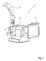
- Fig. 1 illustrates a generalized overview of a wood chipping machine 1 comprising a feed inlet 2, a feeding device 3, a disk housing 4 and an outlet pipe 5.
- material 10 such as whole trees, branches or pieces of wood, which is to be disintegrated into wood chips 26, is fed into a feed inlet 2.
- the feeding device 3 behind the feed inlet 2 catches the material 10 and drags it towards the disk housing 4, inside which the knives 16 on a rotating cutter disk 15 chip the fed material 10 into wood chips 26.
- ejector vanes 25 mounted behind the cutter disk 15 the wood chips 26 are expelled from the wood chipping machine 1 through the outlet pipe 5.
- Fig. 2 illustrates a generalized overview of the main parts of the feeding device 3 and the disk housing 4 of a wood chipping machine 1 as known from the art.
- the feeding device comprises two feed-in rollers 6, 7 rotating in opposite directions 8, 9 about parallel axes of rotation.
- the rotation 8, 9 of the rollers 6, 7 drags the material 10 in a direction 11 towards the disk housing 4.
- the rotational axes of the feed-in rollers 6, 7 are horizontal. It should be noted, however, that the axes can also be vertical or form any angle with the horizontal plane as long as they are parallel.
- the disk housing 4 basically comprises a front sheet 12, a back sheet 13 and a disk casing 14, enclosing a cutter disk 15 along its front side, its back side and its rim, respectively.
- the cutter disk 15 comprises a number of cutter knives 16 arranged with their cutting edges in a substantially radial plane on the front side of the disk 15, which is arranged with its axial direction substantially parallel to the feed-in direction 11 of the feeding device 3.
- the disk housing 4 further comprises a backstop 17 arranged to hold the material 10 in position while it is being chipped by the cutter knives 16 during rotation 18 of the cutter disk 15.
- the disk housing 4 comprises an ejector shielding 19, which is a kind of extra disk casing covering the ejection opening 20 through which the wood chips 26 are ejected 21 from the disk housing 4.
- the ejector shielding 19 covers the ejection opening 20 in front of the cutter disk 15 and over the rim of the disk 15 but leaves the ejection opening 20 open behind the cutter disk 15.
- the ejector shielding 19 ensures that material 10 on the front side of the cutter disk 15, that has not yet been disintegrated, cannot be ejected from the disk housing 15, whereas wood chips 26 on the back side of the cutter disk 15, that has already been disintegrated, is ejected through the ejection opening 20.
- Fig. 3a and 3b show a cutter disk 15 as seen from the front side and the back side, respectively.
- each cutter knife 16 there is a chip slot 22 formed through the disk 15, through which the wood chips 26 pass from the front side to the back side of the disk 15 after being cut by a knife 16.
- the purpose of the edge blades 23 is to break the otherwise circular periphery of the cutter disk 15 and clean out the area between the rim of the cutter disk 15 and the disk casing 14 in order to avoid that any material 10 gets stuck in this area, where it can get very hot and even catch fire due to the friction between the stuck material 10 and the rotating cutter disk 15.
- the diameter of cutter disks as known from the art are within a range from around 300 mm to around 1400 mm with the most typical diameter being around 1000 mm, but even larger cutter disks can be seen in large industrial wood chipping machines.
- the cutter disk 15 is mounted on and driven by a drive shaft 24, which is again driven by some kind of drive means for driving the rotation of the rotor.
- These drive means may comprise an external force, such as the engine of a tractor or another machine, or an internal combustion engine or an electrical motor integrated within the wood chipping machine assembly 1.
- a so-called “revolution guard” is preferably installed within the wood chipping machine 1.
- the "revolution guard” is an electronic device monitoring the number of revolutions per minute of the rotor and disabling the function of the feeding device 3, if the number of resolutions gets too low. This is done in order to avoid "choking" of the machine or engine driving the rotation of the rotor, because it is very difficult to start up the wood chipping machine 1 again, if it is filled up with material 10 to be chipped. As soon as the number of revolutions is back to normal, the function of the feeding device 3 is enabled again, and the machine 1 resumes working normally.
- figs. 4a and 4b The operational principle of a wood chipping machine 1 as known from the art using a cutter disk 15 is illustrated in figs. 4a and 4b , where fig. 4b is an enlargement of a central part of fig. 4a .
- the material 10 to be disintegrated is drawn into the wood chipping machine 1 by the feed-in rollers 6, 7 of the feeding device 3 towards the cutter disk 15.
- the end of the material 10 is chipped by one of the cutter knives 16 rotating with the cutter disk 15, the material 10 being held in position by the backstop 17.
- the material 10 that has been chipped off and has now become wood chips 26 is forced through the chip slot 22 behind the knife 15 by the cutting force of the knife 15 and ends up at the back side of the cutter disk 15, from where it is ejected from the wood chipping machine 1 by being shovelled out by the ejector vanes 25.
- the small arrows in fig. 4a illustrate the flow of material 10, 26 through the machine.
- Fig. 5a and fig. 5b illustrates two different principles of mounting the cutter knives 16 on the cutter disk 15.
- the size of the wood chips 26 is defined by the cutting height 28, i.e. the height of the edge of the knife 16 over the surface of the cutter disk 15.
- the cutting height 28 i.e. the height of the edge of the knife 16 over the surface of the cutter disk 15.
- other factors can also affect the size of the wood chips 26. If, for instance, the material 10 to be disintegrated is drawn too slowly towards the cutter disk 15 by the feeding device 3, so that it does not reach the front surface of the disk 15 before it is chipped by a knife 16, the wood chips will be smaller than the maximum size defined by the cutting height 28.
- a cutter knife 16 is mounted in a recess on the front side of the cutter disk 15 with the blade of the knife 16 arranged in a plane that is parallel to the front plane of the disk 15. If needed, a spacer 27 can be mounted between the cutter knife 16 and the cutter disk 15 for adjustment of the cutting height 28.
- the cutter knife 16 is mounted within the chip slot 22 through the cutter disk 15 along a wall of the slot 22 that is angled with respect to the radial plane of the cutter disk 15.
- the cutting height 28 is adjusted by sliding the knife 16 along the wall of the chip slot 22 onto which the knife 16 is mounted.
- pieces of material 10 sometimes pass through the chip slots 22 from the front side to the back side of the cutter disk 15 without being chipped into suitable sized wood chips 26 by the cutter knives 16. This is particularly a problem with end pieces of the material 10, which can be dragged through the chip slot 22 by the knife 16 instead of being cut, because they are too short to be held in position by the backstop 17 when they are met by the edge of a knife 16.
- the maximum width of a piece of material 10 passing through a chip slot 22 equals the radial width of the chip slot 22, and the maximum height of such a piece of material 10 equals the distance between the edge of the cutter knife 16 and the opposite edge of the associated chip slot 22.
- the maximum length of a piece of material passing through a chip slot 22 depends on the cutting height 28, the speed with which the material 10 is fed towards the cutter disk 15 by the feeding device 3 and, only if the cutter disk 15 rotates very slowly, of the rotational speed of the cutter disk 15.
- oversized pieces of material 10 do not only travel from the front side to the back side of the cutter disk 15 through the chip slots 22. Also, some pieces of material 10 are seen travelling along the front side of the cutter disk 15 to its periphery and passing by the rim of the cutter disk 15 to its back side. Obviously, the material 10 is not supposed to move this way around the cutter disk 15, but it is very difficult to avoid that at least a limited amount of material 10 passes along the front side of the cutter disk 15 towards the rim because of the gap between the cutter disk 15 and the front sheet 12 of the disk housing 4. This gap is necessary to make room for the cutter knives 16 which extend at least the cutting height 28 from the front side of the cutter disk 15. Also, a certain tolerance between the cutter knives 16 and the front sheet 12 is needed.
- a preferred embodiment of the present invention comprising a sieving device 29 fixed to the front sheet 12 of the disk housing 4, represents a solution to the problem of oversized pieces of material 10 passing to the back side of the cutter disk 15, whether the pieces of material 10 pass through chip slots 22 or by the rim of the cutter disk 15.
- This embodiment which causes all material 10 on the back side of the cutter disk 15 to pass through the sieving device 29 before it reaches the ejection opening 20 of the disk housing 4, is described in details with references to the following figures.
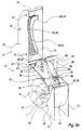
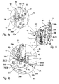
- Figs. 6a and 6b illustrate an opened disk housing 4 of a wood chipping machine 1 according to the above-mention embodiment of the invention as seen from two different angles.
- the disk housing 4 is divided into an upper part 30 and a bottom part 31.
- the sieving device 29 which consists of three parts, namely a sieving plate 32, a sealing plate 33 and a mounting plate 34, each of which three parts are divided into an upper and a bottom part. Dividing the disk housing 4 and the sieving device 29 into upper and bottom parts facilitates an easy access to the rotor for maintenance and repair as well as for replacement of parts that have been damaged or are simply worn out.
- the disk housing 4 and/or the sieving device 29 can be undivided, or they can be divided into more than two parts each for easy access to the interior of the disk housing 4.
- the rotor in order to enable the disassembly of the sieving device 29 into its upper and bottom parts, the rotor should be rotated 90° as compared to the figure to get the ejector vane 25 out of the way.
- the main part of the sieving device 29 is the sieving plate 32 containing the openings 35 of the sieving device 29.
- the sieving plate 32 is also the part of the sieving device 29 forming a cylindrical surface.
- the sealing plate 33 is the part of the sieving device 29 that extends in a radial direction within the outer perimeter of the rear disk 36 in close proximity with the back side of the rear disk 36.
- the sealing plate 33 can also be placed in a recess along the back side edge of the rear disk 36, if the thickness of the rear disk 36 is large enough to leave space for such a recess.
- the mounting plate 34 is used for fixing the sieving device 29 to the front sheet 12 of the disk housing 4.
- the mounting plate 34 is fixed to the disk housing 4 by means of a number of bolts 37. This is advantageous because it makes it possible to replace the sieving device 29, either because of wear or because another size of openings 35 is wanted. If the mounting plate 34 were welded directly to the disk housing 4, such a replacement would not be possible without also replacing the whole front sheet 12 of the disk housing 4.
- the rear disk 36 is provided with a number of air passages 38 formed through the disk 36 near its centre. These air passages 38 constitute the main inlet for the air being blown out through the ejection opening 20 and the outlet pipe 5 during operation of the wood chipping machine 1. Due to the centrifugal properties of the air flow within the rotor, which air flow forces the wood chips 26 between the cutter disk 15 and the rear disk 36 to move towards the sieving device 29, placed at the periphery of the disks 15, 36, and due to the direction of the motion of the air being sucked into the rotor through the air passages 38, the wood chips 26 are not inclined to leave the rotor through the air passages 38 during operation of the machine 1. Anyhow, the air passages 38 can be formed as a plurality of small openings, or they can be covered by a mesh in order to ensure that no material leaves the rotor this way.
- the rear disk 36 has substantially the same diameter as the cutter disk 15, thus facilitating the use of a sieving plate 32 shaped as a cylindrical surface as also shown in the figure. If, instead, the rear disk 36 is chosen to have a smaller diameter than the cutter disk 15, the use of a sieving plate 32 shaped as a conical surface is facilitated.
- a solution is more complicated, but it has the advantage that the wood chips 26 passing through the sieving device 29 are directed towards the back of the disk housing 4 and, thus, towards the ejector vanes 25 and the ejection opening 20 of the disk housing 4.
- the cutter blades 39 are mounted between the back side of the cutter disk 15 and the front side of the rear disk 36 by means of supports 40, which serve two purposes. Apart from supporting the cutter blades 39 and keeping them in the right positions to interact properly with the sieving device 29, the supports 40 also contribute to the formation of a centrifugal flow of air within the rotor forcing the wood chips 26 towards the sieving device 29.
- the cutter blades 39 interact with the edges of the openings 35 of the sieving device 29 to disintegrate the wood chips 26, until the wood chips 26 have been divided into pieces small enough to pass through the openings 35.
- the cutter blades 39 extend towards the feed inlet 2 of the wood chipping machine 1 through recesses cut out from the rim of the cutter disk 15. In this way, also the part of the sieving plate 32 surrounding the rim of the cutter disk 15 can be used for disintegrating and sieving the wood chips 26.
- an ejector vane 25 extending in two directions perpendicular to each other is shown in figs. 6a and 6b , mounted to the back side of the rear disk 36.
- the reason for the shown ejector vane 25 to be cut of in an oblique angle is to make room for reinforcement of the connection between the sieving plate 32 and the mounting plate 34 of the sieving device 29, should it be necessary.
- the cutter knives 16 are mounted in a plane parallel to the radial plane of the cutter disk 15, each in close proximity with a chip slot 22.
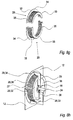
- Fig. 7 illustrates the same opened disk housing as shown in fig. 6a , only with some parts of the disk housing 4, the sieving device 29 and the rotor cut away. First and foremost, this makes the interaction between the cutter blades 39 and the sieving plate 32 visible, but also the mounting of the cutter blades 39 on their supports 40 and the mounting of the supports 40 between the cutter disk 15 and the rear disk 36 are more easily seen than in fig 6a .
- Figs. 8a-8j is a series of illustrations showing an example of how the rotor can be assembled and arranged in the disk housing 4.
- Figs. 8a and 8b illustrate a cutter disk 15 as known from the art as seen from the front side and from the back side, respectively.
- the cutter disk 15, which is mounted on a drive shaft 24, comprises cutter knives 16, chip slots 22 and edge blades 23.
- Fig. 8g illustrates the two parts of the sieving device 29, each comprising a part of the sieving plate 32, the sealing plate 33 and the mounting plate 34.
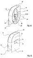
- Fig. 9 illustrates a disk housing 4 with some parts cut away to show the path of wood chips 26a, 26b passing through the disk housing 4 of a wood chipping machine 1 according to the present invention.
- Figs. 9a and 9b are enlargements of parts of fig. 9 , illustrating the path of the wood chips 26a, 26b through the cutter disk 15 and through the sieving device 29, respectively.
- the reference number 26 generally referring to wood chips, has been split up into two reference numbers 26a and 26b, referring to wood chips 26a containing oversized pieces and perfect wood chips 26b with no oversized pieces, respectively.
- Figure 9b similarly illustrates how oversized pieces of wood chips 26a are disintegrated between a cutter blade 39 and the sieving plate 32, whereupon they pass through openings 35 of the sieving device 29, now being referred to as perfect wood chips 26b. Furthermore, this figure clearly shows the bolts 42 with which the cutter blade supports 40 are mounted to the back side of the cutter disk 15, and the bolts 43, with which the cutter blades 39 are mounted to the supports 40.
Landscapes
- Engineering & Computer Science (AREA)
- Life Sciences & Earth Sciences (AREA)
- Manufacturing & Machinery (AREA)
- Mechanical Engineering (AREA)
- Wood Science & Technology (AREA)
- Forests & Forestry (AREA)
- Food Science & Technology (AREA)
- Crushing And Pulverization Processes (AREA)
- Debarking, Splitting, And Disintegration Of Timber (AREA)
Priority Applications (4)
| Application Number | Priority Date | Filing Date | Title |
|---|---|---|---|
| EP07019901A EP2047911A1 (de) | 2007-10-11 | 2007-10-11 | Holzhackmaschine mit peripherer Sieb- und Desintegrationsvorrichtung |
| EP08801388A EP2209556B1 (de) | 2007-10-11 | 2008-10-10 | Holzhackmaschine mit Umfangssieb und Zerkleinerungsvorrichtung und Verfahren zur Herstellung von Holzhackschnitzel |
| DK08801388.3T DK2209556T3 (da) | 2007-10-11 | 2008-10-10 | Flishugningsmaskine med perifer sigte- og neddelingsanordning samt fremgangsmåde til fremstilling af træflis |
| PCT/DK2008/000354 WO2009046719A1 (en) | 2007-10-11 | 2008-10-10 | Wood chipping machine with peripheral sieving and disintegration device |
Applications Claiming Priority (1)
| Application Number | Priority Date | Filing Date | Title |
|---|---|---|---|
| EP07019901A EP2047911A1 (de) | 2007-10-11 | 2007-10-11 | Holzhackmaschine mit peripherer Sieb- und Desintegrationsvorrichtung |
Publications (1)
| Publication Number | Publication Date |
|---|---|
| EP2047911A1 true EP2047911A1 (de) | 2009-04-15 |
Family
ID=39126144
Family Applications (2)
| Application Number | Title | Priority Date | Filing Date |
|---|---|---|---|
| EP07019901A Withdrawn EP2047911A1 (de) | 2007-10-11 | 2007-10-11 | Holzhackmaschine mit peripherer Sieb- und Desintegrationsvorrichtung |
| EP08801388A Revoked EP2209556B1 (de) | 2007-10-11 | 2008-10-10 | Holzhackmaschine mit Umfangssieb und Zerkleinerungsvorrichtung und Verfahren zur Herstellung von Holzhackschnitzel |
Family Applications After (1)
| Application Number | Title | Priority Date | Filing Date |
|---|---|---|---|
| EP08801388A Revoked EP2209556B1 (de) | 2007-10-11 | 2008-10-10 | Holzhackmaschine mit Umfangssieb und Zerkleinerungsvorrichtung und Verfahren zur Herstellung von Holzhackschnitzel |
Country Status (3)
| Country | Link |
|---|---|
| EP (2) | EP2047911A1 (de) |
| DK (1) | DK2209556T3 (de) |
| WO (1) | WO2009046719A1 (de) |
Cited By (11)
| Publication number | Priority date | Publication date | Assignee | Title |
|---|---|---|---|---|
| FR2946913A1 (fr) * | 2009-06-23 | 2010-12-24 | Michel Bugnot | Broyeur de vegetaux pour la production de plaquettes ou particules de bois calibrees |
| CN102773138A (zh) * | 2011-05-09 | 2012-11-14 | 吴建华 | 一种食用菌栽培物料粉碎装置 |
| EP2708340A1 (de) * | 2012-09-13 | 2014-03-19 | HoGHa GmbH | Vorrichtung zum Sortieren von Hackschnitzeln |
| EP2650050B1 (de) * | 2012-04-10 | 2016-06-01 | PC Maskiner ApS | Holzhackmaschine mit peripherer Sieb- und Desintegrationsvorrichtung |
| CN106166510A (zh) * | 2016-08-26 | 2016-11-30 | 天津市金桥焊材集团有限公司 | 一种应用于焊条生产的粉碎装置 |
| CN106239590A (zh) * | 2016-08-08 | 2016-12-21 | 上海大学 | 一种盘式削片机 |
| GR1008963B (el) * | 2016-03-31 | 2017-02-22 | Σταυρος Μιχαηλ Καρυωτακης | Θρυμματιστης κλαδιων με διαιρετη περιστρεφομενη κεφαλη κατεργασιας απο μασιφ ατσαλι ή χαλυβα με λεπιδες που θρυμματιζουν με βαση την μεθοδο της πλανισης |
| CN108818855A (zh) * | 2018-07-12 | 2018-11-16 | 唐伟 | 轨道废弃枕木切割锯末机 |
| CN108908619A (zh) * | 2018-07-12 | 2018-11-30 | 唐伟 | 一种轨道废弃枕木切割锯末设备 |
| GR20170100364A (el) * | 2017-07-24 | 2019-04-04 | Σταυρος Μιχαλη Καριωτακης | Καταστροφεας κλαδιων με συστημα προωθησης των κλαδιων και συστημα επεξεργασιας των κλαδιων για παραγωγη βιομαζας |
| CN112873435A (zh) * | 2021-01-18 | 2021-06-01 | 罗成 | 一种工业用木条定距切割机 |
Families Citing this family (5)
| Publication number | Priority date | Publication date | Assignee | Title |
|---|---|---|---|---|
| CN104884171B (zh) * | 2012-12-24 | 2016-08-17 | 车战斌 | 粉碎机 |
| DE102013202454B4 (de) * | 2013-02-14 | 2015-02-05 | Technische Universität Dresden | Vorrichtung zum Homogenisieren von Holzhackschnitzeln |
| DE102017103855A1 (de) | 2017-02-24 | 2018-08-30 | Albach Maschinenbau GmbH | Wurfbeschleuniger einer holzverarbeitenden Maschine |
| CN109046712B (zh) * | 2018-07-19 | 2020-07-24 | 合肥汇之新机械科技有限公司 | 一种园林绿化用废弃物回收装置 |
| CN115228570A (zh) * | 2022-07-21 | 2022-10-25 | 董强 | 一种具有防止物料缠绕功能的撕碎机 |
Citations (4)
| Publication number | Priority date | Publication date | Assignee | Title |
|---|---|---|---|---|
| DE1653062A1 (de) * | 1966-07-22 | 1971-10-07 | Beloit Corp | Holzzerspanmaschine |
| AT361762B (de) * | 1979-11-23 | 1981-03-25 | Buchmann & Co | Schrotmuehle |
| CH625390A5 (en) * | 1977-10-28 | 1981-09-30 | Scherz & Co Maschinen Und Kraf | Bruising mill for cereals |
| DE8233879U1 (de) * | 1982-12-02 | 1985-08-22 | Wissing, Heinrich, 4284 Heiden | Mühle zum Zerkleinern von körnigen Stoffen, insbesondere von Mais, mit einer waagerechten Antriebswelle |
Family Cites Families (4)
| Publication number | Priority date | Publication date | Assignee | Title |
|---|---|---|---|---|
| DE1507525A1 (de) * | 1963-10-08 | 1969-07-17 | Fellner & Ziegler Gmbh | Zerkleinerungsmaschine,insbesondere fuer Kunststoffabfaelle |
| DE2616847A1 (de) * | 1976-04-15 | 1977-10-27 | Pallmann Kg Maschf | Mit einem profil versehene leiste fuer eine mahlbahn |
| US5054703A (en) * | 1990-10-12 | 1991-10-08 | Wood Technology, Inc. | Stump chipper knife assembly |
| FI95109C (fi) * | 1994-06-10 | 1995-12-27 | Pekka Lahti | Rumpuhakkurilaitteisto |
-
2007
- 2007-10-11 EP EP07019901A patent/EP2047911A1/de not_active Withdrawn
-
2008
- 2008-10-10 EP EP08801388A patent/EP2209556B1/de not_active Revoked
- 2008-10-10 DK DK08801388.3T patent/DK2209556T3/da active
- 2008-10-10 WO PCT/DK2008/000354 patent/WO2009046719A1/en active Application Filing
Patent Citations (4)
| Publication number | Priority date | Publication date | Assignee | Title |
|---|---|---|---|---|
| DE1653062A1 (de) * | 1966-07-22 | 1971-10-07 | Beloit Corp | Holzzerspanmaschine |
| CH625390A5 (en) * | 1977-10-28 | 1981-09-30 | Scherz & Co Maschinen Und Kraf | Bruising mill for cereals |
| AT361762B (de) * | 1979-11-23 | 1981-03-25 | Buchmann & Co | Schrotmuehle |
| DE8233879U1 (de) * | 1982-12-02 | 1985-08-22 | Wissing, Heinrich, 4284 Heiden | Mühle zum Zerkleinern von körnigen Stoffen, insbesondere von Mais, mit einer waagerechten Antriebswelle |
Cited By (14)
| Publication number | Priority date | Publication date | Assignee | Title |
|---|---|---|---|---|
| FR2946913A1 (fr) * | 2009-06-23 | 2010-12-24 | Michel Bugnot | Broyeur de vegetaux pour la production de plaquettes ou particules de bois calibrees |
| EP2266768A1 (de) * | 2009-06-23 | 2010-12-29 | Michel Bugnot | Broyeur de végétaux pour la production de plaquettes ou particules de bois |
| CN102773138A (zh) * | 2011-05-09 | 2012-11-14 | 吴建华 | 一种食用菌栽培物料粉碎装置 |
| EP2650050B1 (de) * | 2012-04-10 | 2016-06-01 | PC Maskiner ApS | Holzhackmaschine mit peripherer Sieb- und Desintegrationsvorrichtung |
| EP2708340A1 (de) * | 2012-09-13 | 2014-03-19 | HoGHa GmbH | Vorrichtung zum Sortieren von Hackschnitzeln |
| GR1008963B (el) * | 2016-03-31 | 2017-02-22 | Σταυρος Μιχαηλ Καρυωτακης | Θρυμματιστης κλαδιων με διαιρετη περιστρεφομενη κεφαλη κατεργασιας απο μασιφ ατσαλι ή χαλυβα με λεπιδες που θρυμματιζουν με βαση την μεθοδο της πλανισης |
| CN106239590A (zh) * | 2016-08-08 | 2016-12-21 | 上海大学 | 一种盘式削片机 |
| CN106166510A (zh) * | 2016-08-26 | 2016-11-30 | 天津市金桥焊材集团有限公司 | 一种应用于焊条生产的粉碎装置 |
| GR20170100364A (el) * | 2017-07-24 | 2019-04-04 | Σταυρος Μιχαλη Καριωτακης | Καταστροφεας κλαδιων με συστημα προωθησης των κλαδιων και συστημα επεξεργασιας των κλαδιων για παραγωγη βιομαζας |
| GR1009916B (el) * | 2017-07-24 | 2021-01-28 | Σταυρος Μιχαλη Καριωτακης | Καταστροφεας κλαδιων με συστημα προωθησης των κλαδιων και συστημα επεξεργασιας των κλαδιων για παραγωγη βιομαζας |
| CN108818855A (zh) * | 2018-07-12 | 2018-11-16 | 唐伟 | 轨道废弃枕木切割锯末机 |
| CN108908619A (zh) * | 2018-07-12 | 2018-11-30 | 唐伟 | 一种轨道废弃枕木切割锯末设备 |
| CN112873435A (zh) * | 2021-01-18 | 2021-06-01 | 罗成 | 一种工业用木条定距切割机 |
| CN112873435B (zh) * | 2021-01-18 | 2022-08-16 | 吉荣家具有限公司 | 一种工业用木条定距切割机 |
Also Published As
| Publication number | Publication date |
|---|---|
| WO2009046719A1 (en) | 2009-04-16 |
| EP2209556A1 (de) | 2010-07-28 |
| DK2209556T3 (da) | 2013-04-29 |
| EP2209556B1 (de) | 2013-01-16 |
Similar Documents
| Publication | Publication Date | Title |
|---|---|---|
| EP2047911A1 (de) | Holzhackmaschine mit peripherer Sieb- und Desintegrationsvorrichtung | |
| US8844853B2 (en) | Reducing component for a comminution machine | |
| US7798436B2 (en) | Portable rotary chipper apparatus | |
| ES2424093T3 (es) | Dispositivo para triturar producto de carga | |
| US6036125A (en) | Wood chipper | |
| EP3061581B1 (de) | Zerkleinerer | |
| US5060873A (en) | Wood chipper fin chip separator | |
| AU2022307036B2 (en) | Impellers for cutting machines and cutting machines equipped with impellers | |
| US20200331000A1 (en) | Rotor chamber fin for chipper shredder | |
| US7946513B2 (en) | Device and method for improving grinding efficacy in gravity-fed grinding machines | |
| EP2650050B1 (de) | Holzhackmaschine mit peripherer Sieb- und Desintegrationsvorrichtung | |
| US9186683B2 (en) | Apparatus for comminuting fibrous materials | |
| CN116917097A (zh) | 用于切割机的叶轮和配备有该叶轮的切割机 | |
| CN205323926U (zh) | 双向切割木材破碎机 | |
| JP2704503B2 (ja) | 破砕装置 | |
| JP4441274B2 (ja) | 粉砕分別システム | |
| CN213315293U (zh) | 一种粉碎机构及粉碎机 | |
| EP2668839B1 (de) | Häckselvorrichtung | |
| CN108672037B (zh) | 一种超微粉碎装置 | |
| EP3221056B1 (de) | Entladungsvorrichtung für zerkleinerte organische stoffe | |
| AU2022206585A1 (en) | A mulcher | |
| WO2023195848A1 (en) | Knife cassette and cutting device for cutting leaves from flowers and plants | |
| JPH0647078B2 (ja) | 破砕装置 | |
| JP2005279593A (ja) | 破砕機における破砕物の粒度調整方法、破砕機及び破砕作業車 | |
| JPH0729066B2 (ja) | 寸断方法およびその装置 |
Legal Events
| Date | Code | Title | Description |
|---|---|---|---|
| PUAI | Public reference made under article 153(3) epc to a published international application that has entered the european phase |
Free format text: ORIGINAL CODE: 0009012 |
|
| AK | Designated contracting states |
Kind code of ref document: A1 Designated state(s): AT BE BG CH CY CZ DE DK EE ES FI FR GB GR HU IE IS IT LI LT LU LV MC MT NL PL PT RO SE SI SK TR |
|
| AX | Request for extension of the european patent |
Extension state: AL BA HR MK RS |
|
| AKX | Designation fees paid | ||
| REG | Reference to a national code |
Ref country code: DE Ref legal event code: 8566 |
|
| STAA | Information on the status of an ep patent application or granted ep patent |
Free format text: STATUS: THE APPLICATION IS DEEMED TO BE WITHDRAWN |
|
| 18D | Application deemed to be withdrawn |
Effective date: 20091016 |