EP2047769A1 - Personensitz mit einer Sitzfederung - Google Patents
Personensitz mit einer Sitzfederung Download PDFInfo
- Publication number
- EP2047769A1 EP2047769A1 EP08165971A EP08165971A EP2047769A1 EP 2047769 A1 EP2047769 A1 EP 2047769A1 EP 08165971 A EP08165971 A EP 08165971A EP 08165971 A EP08165971 A EP 08165971A EP 2047769 A1 EP2047769 A1 EP 2047769A1
- Authority
- EP
- European Patent Office
- Prior art keywords
- backrest
- seat
- support
- wippfeder
- spring
- Prior art date
- Legal status (The legal status is an assumption and is not a legal conclusion. Google has not performed a legal analysis and makes no representation as to the accuracy of the status listed.)
- Granted
Links
Images


Classifications
-
- A—HUMAN NECESSITIES
- A47—FURNITURE; DOMESTIC ARTICLES OR APPLIANCES; COFFEE MILLS; SPICE MILLS; SUCTION CLEANERS IN GENERAL
- A47C—CHAIRS; SOFAS; BEDS
- A47C7/00—Parts, details, or accessories of chairs or stools
- A47C7/36—Support for the head or the back
- A47C7/40—Support for the head or the back for the back
- A47C7/44—Support for the head or the back for the back with elastically-mounted back-rest or backrest-seat unit in the base frame
- A47C7/445—Support for the head or the back for the back with elastically-mounted back-rest or backrest-seat unit in the base frame with bar or leaf springs
-
- A—HUMAN NECESSITIES
- A47—FURNITURE; DOMESTIC ARTICLES OR APPLIANCES; COFFEE MILLS; SPICE MILLS; SUCTION CLEANERS IN GENERAL
- A47C—CHAIRS; SOFAS; BEDS
- A47C1/00—Chairs adapted for special purposes
- A47C1/02—Reclining or easy chairs
- A47C1/022—Reclining or easy chairs having independently-adjustable supporting parts
- A47C1/023—Reclining or easy chairs having independently-adjustable supporting parts the parts being horizontally-adjustable seats ; Expandable seats or the like, e.g. seats with horizontally adjustable parts
-
- A—HUMAN NECESSITIES
- A47—FURNITURE; DOMESTIC ARTICLES OR APPLIANCES; COFFEE MILLS; SPICE MILLS; SUCTION CLEANERS IN GENERAL
- A47C—CHAIRS; SOFAS; BEDS
- A47C3/00—Chairs characterised by structural features; Chairs or stools with rotatable or vertically-adjustable seats
- A47C3/02—Rocking chairs
- A47C3/025—Rocking chairs with seat, or seat and back-rest unit elastically or pivotally mounted in a rigid base frame
- A47C3/0252—Rocking chairs with seat, or seat and back-rest unit elastically or pivotally mounted in a rigid base frame connected only by an elastic member positioned between seat and base frame
-
- A—HUMAN NECESSITIES
- A47—FURNITURE; DOMESTIC ARTICLES OR APPLIANCES; COFFEE MILLS; SPICE MILLS; SUCTION CLEANERS IN GENERAL
- A47C—CHAIRS; SOFAS; BEDS
- A47C3/00—Chairs characterised by structural features; Chairs or stools with rotatable or vertically-adjustable seats
- A47C3/02—Rocking chairs
- A47C3/025—Rocking chairs with seat, or seat and back-rest unit elastically or pivotally mounted in a rigid base frame
- A47C3/026—Rocking chairs with seat, or seat and back-rest unit elastically or pivotally mounted in a rigid base frame with central column, e.g. rocking office chairs; Tilting chairs
-
- A—HUMAN NECESSITIES
- A47—FURNITURE; DOMESTIC ARTICLES OR APPLIANCES; COFFEE MILLS; SPICE MILLS; SUCTION CLEANERS IN GENERAL
- A47C—CHAIRS; SOFAS; BEDS
- A47C7/00—Parts, details, or accessories of chairs or stools
- A47C7/36—Support for the head or the back
- A47C7/40—Support for the head or the back for the back
- A47C7/402—Support for the head or the back for the back adjustable in height
Definitions
- the invention relates to a passenger seat with a seat surface and a seat suspension and a backrest.
- Seat suspensions are integrated in a variety of embodiments in a variety of chairs and seats.
- the adjustment of the spring force is usually done by a bias of a steel spring by means of a clamping screw.
- Synchronous mechanisms for synchronous adjustment of the inclination of seat and backrest under load are also known in a variety of variants.
- the inclination of the backrest is usually determined in mechanical dependence on the inclination of the seat element. This means that in synchronous mechanisms so far usually every inclination of the seat can be clearly assigned to a particular inclination of the backrest.
- various lever mechanisms have been designed, via which the movement of the backrest support is coupled with the movement of the seat support. These lever mechanisms are cushioned in their movement with a spring.
- the support frame for the seat is made of tubular steel parts. These steel tube parts are bent downwards on the front of the seat by approximately 180 degrees and connected at the end to the leg frame. The support frame itself thus allows a resilient yielding of the seat relative to the leg frame.
- the present invention has set itself the task of creating a passenger seat with a mechanically very little complex synchronous mechanism, which ensures a synchronous tilt adjustment of the backrest and seat element under load.
- This synchronizing mechanism should also allow to provide a device to adjust the seat suspension to the desired seating comfort and the weight of the seat occupant.
- a passenger seat comprises in a known manner a support, a seat element and a backrest, and designed as a Wippfeder seat suspension between the seat member and the support, and formed as a Wippfeder backrest suspension between the seat element and the backrest.
- the seat suspension and the backrest suspension are formed together S-shaped and therefore have to each other then two opposite curvatures.
- the first curvature is formed between the support and the seat member and is concave toward the seat back.
- the second curvature is between the seat element and the Backrest formed.
- the proposed synchronous mechanism is thus designed such that a first spring for cushioning the movement of the seat member and a second spring for cushioning the backrest are arranged in series, so that the load of the backrest brings indeed on the first spring load, but also the second spring loaded.
- the seat support and the backrest support together form a composite spring element which has at least two sections with different spring strengths, which sections are formed from separate spring elements.
- the passenger seat can be equipped very easily with an adjusting device for changing the length of a portion of the rocker spring lying between the fastening points.
- the passenger seat is anatomically shaped so that the seating position is determined by the shape of the seat. This also results in a predetermined spring action when anatomically correct sitting.
- the hardness of the spring can be adjusted. Lighter persons or persons who want a softer suspension, so extend this lying between the attachment sites share of WIPFeder. People who are heavier or want a heavier suspension shorten this proportion of Wippfeder.
- Wippfeder which is arranged on a plane of symmetry of the passenger seat.
- more than one, in particular two, such wippen springs can be provided, which are arranged concomitantly with one another and run in parallel or each have an individual course, possibly symmetrical to one another.
- the Wippfeder can therefore from a leaf spring, more than one leaf spring next to each other and / or one above the other layered, one, two or more round rod springs, one, two or more rod springs consist of rods with multi-surface cross-sections, etc.
- the Wippfeder is U-shaped in the seat suspension. This U-shape is towards the rear end of the seat member, which is the backrest, open ..
- the Wippfeder therefore has a first leg and a second leg, which legs are connected to each other via a connecting web and have free ends towards the rear.
- the first leg is attached to the first attachment point on the support and the second leg carries at the second attachment point the seat surface.
- the center of curvature of the connecting web forming the U corresponds approximately to the location of the virtual rocker axis. Thanks to the adjustment of the distance between the curved connecting web, which is formed between the two legs, and at least one of the attachment points is variable. This change in the distance occurs in the extension direction of the legs.
- both attachment points can be designed adjustable both attachment points. It is expedient to form only an attachment point adjustable. If both attachment points are adjusted equally with the adjustment, the location of a load axis relative to the support remains unchanged. If, on the other hand, only one attachment point is displaced, so does the location of the load relative to the support. However, it has been found that the displacement of the attachment point in the range of 2 to 5 cm sufficient to adjust the spring hardness in the desired range can. This small shift of the load axis does not have to be compensated. Nevertheless, it appears expedient that the two attachment points are formed in a central position on the two legs opposite each other. As a result, the deviations of the load axis from the first attachment point to the support remain low. This has the advantage that only small moments must be absorbed in this first attachment point. This is particularly advantageous when the first attachment point is formed between the Wippfeder and a height lift.
- the second attachment point along the extension direction of the Wippfeder is adjustable. This allows the adjustment to provide directly below the seat element, or even to integrate in the seat element.
- the seat element tilts under load to the rear, so that the seat is lowered back more than the front. This increase in seat tilt as the seat load increases is particularly comfortable because a back is provided.
- the backrest or the backrest support is expediently fastened to the seat element or to the adjusting device.
- the backrest support in a consistent continuation of the simplicity of the construction according to the invention, comprises a rocker spring extending in the extension direction of the backrest support.
- the combination of a first Wippfeder between the seat element and support and a second Wippfeder between the seat element and backrest or in the region of the backrest results in a pleasant synchronous adjustment of the inclination of the backrest and seat element depending on the load on the backrest.
- the simplicity of the construction is particularly pronounced when the backrest support comprises only the second Wippfeder, as well as the seat member and the support are connected by only the first Wippfeder.
- the backrest support may also comprise a first support member which is disposed on the seat member or on the adjusting and extending in the extension direction of the backrest extending arm, and comprise a second support member as an arm extension on this arm of the first support member in the extension direction of the backrest is arranged immovable or displaceable.
- the second carrier element can be bent more elastically under load than the first spring element.
- a backrest is advantageously arranged on the backrest support, which is formed adapted in its direction of extension with a boss and a thoracic spine depression of a back shape.
- This backrest is advantageously attached to a first, upper point and at a second, lower point on the backrest support, formed elastically deformable between these points and slidably mounted in one of the two points in the extension direction of the backrest support.
- This allows the boss to automatically adapt to the shape of the boss leaning on the back.
- This design ensures a certain type of height adjustment of the back, so that it is particularly suitable if a height adjustment described above is not provided.
- the displaceable mounting of the backrest is advantageously provided at its lower end, so that when leaning against a so-called "shirt pull-out effect" is counteracted.
- the backrest is resilient and where it is slidably mounted freely displaceable, so that the deformation of the backrest counteracting force is only the spring force of the backrest itself.
- This spring force can also be supported by an additional spring.
- the illustrated column lifts, but also three-, four- or multi-leg chair frames, as well as, for example, a structurally existing stage or a multiple seats common carrier in question, on which the seat suspension is arranged.
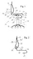
- FIG. 1 an office chair 11 is shown schematically in side view. He has a trolley 13 with five rollers 15 and a column 17 with integrated elevator lift 19, which together form the support 10.
- a Wippfeder 21 is attached on this support 10 .
- the rocker spring 21 forms in the initial region a first leg 22, which first leg 22 is directed at the first attachment point 23 on the support 10 parallel to the support surface of the rolling frame 13. It is bent in the front region of the chair U-shaped and extends after this first curvature 25 again parallel to the first leg 22.
- the second attachment point 27 is formed.
- the rocker spring 21 carries a seat element 31.
- the Wippfeder 21 extends beyond this second attachment point 27 addition. It then forms the backrest support 33 at this second fastening point 27.
- the rocker spring therefore has a second curvature 29, which is opposite to the first one. Following this second curvature 29, an arm 36 of the backrest support 33 projects. On this arm 36, a backrest 37 is attached. It is mounted in an upper attachment point 41 and a lower attachment point 43 thereto.
- a first adjusting device 39 is provided at the second attachment point 27, with which the position of the seat member 31 on the second leg 24 of the Wippfeder 21 can move backwards and forwards.
- an additional (first) adjustment device 39 ' is provided, with which the position of the support of the Wippfeder can be adjusted on the support.
- first adjusting means 39 and 39 ' the length of the effective for the seat suspension portion of the Wippfeder 21 can be adjusted.
- the adjustment between the first attachment point 23 and the second attachment point 27 is effective for the seat suspension.
- Both adjustment devices 39, 39 ' also influence the position of the seat element 31 relative to the support 10 when adjusting the length of this effective section.
- the rocker spring 21 extends beyond the second fastening point 27 and forms a backrest support 33 there.
- the backrest support 33 has the second curvature 29 of the rocker spring 21 in order to be substantially perpendicular to this curvature 29.
- the backrest 37 is attached at this vertical arm 36 of the backrest support 33.
- the backrest 37 is attached to an upper attachment point 41 and to a lower attachment point 43 on the backrest support 33.
- the upper attachment point 41 is a fixed point to which the backrest is fixed immovably but articulated.
- the lower attachment point 43 allows movement of the backrest in the attachment point.
- the backrest 37 can move freely in the lower attachment point with respect to a vertical direction, that is to say parallel to the extension direction of the arm 36 of the backrest support 33.
- first adjusting device 39 at the second attachment point 27 is between seat member 31 and Wippfeder 21, the effect of a length adjustment of the second arm 24 so that with harder adjustment of the seat suspension of the center of gravity further forward in softer setting accordingly further back.
- FIG. 1 is further shown that the backrest support 33 is separate from the seat suspension.
- the backrest support 33 and the seat member 31 is slidably mounted together on the second leg 24 of the Wippfeder 21.
- the actuation of the adjusting device 39 thus causes a change in both the distance of the second attachment point 27 of the first curvature 25 of the Wippfeder and the distance of the arm 36 of the backrest support of this first curvature 25.
- the backrest softer or softer Harder, to the extent that it depends on the seat suspension.
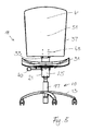
- FIG. 2 In FIG. 2 is shown a possibility of height adjustment of the backrest.
- an arm extension 35 ' On a short-cut arm 36 of the backrest support 33, an arm extension 35 'is slidably disposed.
- a second adjusting device 49 between the arm 36 and the arm extension 35' is provided. This second adjusting device 49 may be formed identically with the first adjusting device 39.
- the separation of the backrest support in a first portion with the second curvature 29 and a short arm 36 and an arm extension also has the advantage that the spring characteristics of both parts can be selected separately. This selectability of the spring properties is also given between the seat suspension and the backrest suspension, when the Wippfeder is separated in the region of the second attachment point.
- an office chair 11 is shown. He has a trolley 13 with five rollers 15 and a column 17 with integrated elevator lift 19, which together form the support 10. His Wippfeder 21 is divided into three parts. It comprises a first part, which is attached to the support 10 at the first attachment point 23 and is U-shaped. This first part of the Wippfeder 21 carries an adjusting device 39, by means of which adjustment, the seat member 31 is adjustable together with the backrest support 33. The backrest support 33 with the arm extension 35 'therefore forms a second and a third part of the rocker spring 21. The second part of the rocker spring has the second curvature 29 and is connected to the arm extension 35' via the second adjustment device 49. With the operation of the second adjusting device 49, the upper and lower attachment point 41,43 between the arm extension 35 'and the backrest 37 can be moved simultaneously in height.
- the adjusting devices 39 and 49 are identical. They have an adjustment block, in which the adjustment takes place via a toothed wheel or a worm wheel and a row of teeth. They have an operating wheel 40 or 50, with which the gear or the worm wheel can be rotated.
- the lower attachment point of the backrest 37 on the back support 33 is fixed and allows only a pivoting of the backrest about a horizontal axis.
- the upper attachment point allows a shift between the backrest 37 and the backrest support 33. Such a shift occurs when the backrest is loaded.
- the boss is flattened and / or changed in its position.
- the slider 57 abuts the receptacle 55 and does not allow detachment of the backrest 37 from the backrest support 33rd
- FIGS. 6 and 7 illustrated embodiment differs from the example described above FIGS. 3 to 5 essentially in that the backrest 37 at its lower attachment point 43 slidably and in the upper attachment point 41 is articulated but immovably fixed to the backrest support 33. Instead of a displaceability at the lower attachment point is preferred to articulate a pivot lever on the backrest and the backrest support. This ensures virtually the same freedom of movement.
- a spring may be provided, with which the backrest is biased.
- FIGS. 6 and 7 no displacement device 49 between the first support member 35 and the second support member 35 'present. Nevertheless, a first 35 and a second 35 'support member are present.
- the first support member 35 is resilient only to a small extent, since it is made of a stainless steel.
- the second support part 35 ' is made of spring steel and gives significantly under load.
- These two support members 35,35 ' are screwed or riveted together in a defined position. It is possible to allow different positions through a plurality of perforations or a slot in the first carrier part 35 and / or in the second carrier part 35 '. By loosening the screws and re-attaching the second support member 35 'on the arm 36 of the first support member, therefore, the height position of the backrest can be adjusted.
- the office chair is according to FIGS. 6 and 7 equipped with armrests.
- the illustrations do not include upholstery and trim parts of the chair. However, such can be provided.
- the teaching according to the invention is to be used in particular for office chairs. But it can also be applied to all other passenger seats, such as seats in means of transport, especially in vehicle seats. Very suitable is the seat mechanism according to the invention for chairs, which should be indestructible despite low acquisition costs, such as school seating, seats in public areas, waiting rooms, but also object chairs. An angular adjustment between the individual parts of the Wippfeder can be provided.
- the Wippfeder 21, or each part of the Wippfeder 21 may also be formed as Wippfederpacket and therefore be a bunch of multiple Wippfedern.
- Such a Wippfederet may include a first number of Wippfedern extending between the support and the seat part. From the seat part to the lower attachment point of the backrest a second, smaller number of Wippfedern is provided. Between the lower and the upper fastening point, a third, even smaller number of Wippfedern is provided.
- the effective spring length can also be adjusted by having a second element accompanying the rocker spring, and a slider connecting the rocker spring to the second element. Depending on the location of this slide, a longer or shorter proportion of the rocker spring is able to deform independently of the second element.
- the second element may be a wiper spring with a higher spring force.
- the backrest suspension may therefore comprise a Wippfeder that extends below the seat member 31, but in the region of the first support member 35 has a slidable slide. With this, the effective spring length of the backrest support, and thus the strength of the spring force of the backrest support can be adjusted. The same is appropriate in the field of seat suspension.
Abstract
Description
- Die Erfindung betrifft einen Personensitz mit einer Sitzfläche und einer Sitzfederung und einer Rückenlehne.
- Sitzfederungen sind in einer Vielzahl von Ausführungsformen in den unterschiedlichsten Stühlen und Sitzen integriert. Die Verstellung der Federkraft erfolgt in aller Regel durch eine Vorspannung einer Stahlfeder mittels einer Spannschraube.
- Synchronmechaniken zur synchronen Verstellung der Neigung von Sitzelement und Rückenlehne unter Last sind ebenfalls in einer Vielzahl von Varianten bekannt. Dabei ist die Neigung der Rückenlehne in der Regel in mechanischer Abhängigkeit zur Neigung des Sitzelements festgelegt. Das heisst, dass bei Synchronmechaniken bisher meist jede Neigung der Sitzfläche einer bestimmten Neigung der Rückenlehne eindeutig zugeordnet werden kann. Um dies zu erreichen sind diverse Hebelmechaniken entworfen worden, über welche die Bewegung des Lehnenträgers mit der Bewegung des Sitzträgers gekoppelt ist. Diese Hebelmechaniken sind in ihrer Bewegung mit einer Feder abgefedert.
- Aus der schweizerischen Patentschrift
CH 164140 - Aus der Offenlegungsschrift
US 2003/ 0234566 ist ein Sessel bekannt, bei dem das Traggestell für den Sitz mit zwei Hülsen auf zwei etwa horizontal verlaufenden Armen verschieblich gelagert ist. Jeder dieser Arme ist ein Schenkel eines um 180 Grad gebogenen Federelements, das am Beingestell angeordnet ist. Durch das Verschieben des Traggestells für den Sitz wird der Ort beeinflusst, an dem die Schwerkraft der auf dem Sitz sitzenden Person in das Federelement eingeleitet wird. Daher kann durch das Verschieben das auf die Federelemente wirksame Biegemoment beeinflusst werden. - Aus der Patentschrift
US 4,889,385 ist ein Arbeitsstuhl bekannt, bei dem der Sitz auf einem oberen Arm eines liegenden, u-förmigen Sitzträger angeordent ist. Der untere Arm des u-förmigen Sitzträgers ist an einem Support angeordnet. Der obere Arm geht hinter dem Sitz gebogen in einen Rückenträger über. Die gebogenen Abschnitte dieses einstückigen Sitz- und Rückenträgers sind federnd ausgebildet, während die Arme und der obere Rückenträgerteil steifer ausgebildet sind. Zwischen dem oberen Arm und dem Support sind Stabilisierungselemente vorhanden, die eine seitliche Verschiebung des Sitzes gegenüber dem Support verhindern. - Die vorliegende Erfindung hat sich zur Aufgabe gemacht, einen Personensitz mit einer mechanisch sehr wenig aufwändigen Synchronmechanik, die unter Last eine synchrone Neigungsverstellung von Rückenlehne und Sitzelement gewährleistet, zu schaffen. Diese Synchronmechanik soll ferner erlauben, eine Vorrichtung vorzusehen, um die Sitzfederung auf den gewünschten Sitzkomfort und das Gewicht des Sitzbenützers einzustellen.
- Die Aufgaben der Erfindung werden durch die Ausgestaltung des Personensitzes gemäss unabhängigem Anspruch 1 gelöst.
- Ein Personensitz gemäss der Erfindung umfasst in bekannter Weise einen Support, ein Sitzelement und eine Rückenlehne, sowie eine als Wippfeder ausgebildete Sitzfederung zwischen dem Sitzelement und dem Support, und eine als Wippfeder ausgebildete Lehnenfederung zwischen dem Sitzelement und der Rückenlehne. Bei einem solchen Personensitz sind die Sitzfederung und die Lehnenfederung zusammen S-förmig ausgebildet und weisen daher aneinander anschliessend zwei entgegengesetzte Krümmungen auf. Die erste Krümmung ist zwischen dem Support und dem Sitzelement ausgebildet und ist zur Rückenlehne hin konkav geformt. Die zweite Krümmung ist zwischen dem Sitzelement und der Rückenlehne ausgebildet. Diese Kombination von Sitzfederung und Lehnenfederung ergibt eine Synchronmechanik einfachster Konstruktion. Die synchrone Bewegung von Rückenlehne und Sitzelement unter Last ist durch die Wahl der Federstärken, der Federlängen, der Federbreiten und der Form und Geometrie der Feder vorbestimmbar und durch die Veränderung der Federlängen veränderbar.
- Die vorgeschlagene Synchronmechanik ist somit derart ausgebildet, dass eine erste Feder zum Abfedern der Bewegung des Sitzelements und eine zweite Feder zum Abfedern der Rückenlehne in Serie angeordnet sind, so dass die Belastung der Rückenlehne zwar auf die erste Feder Last bringt, jedoch auch die zweite Feder belastet. Eine Belastung der Sitzfläche allein belastet hingegen lediglich die erste Feder. Erfindungsgemäss bilden der Sitzträger und der Lehnenträger zusammen ein zusammengesetztes Federelement, das wenigstens zwei Abschnitte mit unterschiedlichen Federstärken aufweist, welche Abschnitte aus separaten Federelementen gebildet sind.
- Der Personensitz kann dank der aus mindestens zwei unterschiedlichen Stücken zusammengesetzten Wippfeder sehr einfach mit einer Verstelleinrichtung zum Verändern der Länge eines zwischen den Befestigungsstellen liegenden Anteils der Wippfeder ausgerüstet sein. Zweckmässigerweise ist der Personensitz anatomisch geformt, damit die Sitzposition durch die Form des Sitzes vorgegeben ist. Dadurch ergibt sich auch eine vorgegebene Federwirkung beim anatomisch richtigen Sitzen.
- Durch eine Veränderung der Länge des Wippfederanteils, der zwischen den Befestigungspunkten liegt, kann die Härte der Feder eingestellt werden. Leichtere Personen oder Personen, die eine weichere Federung wünschen, verlängern also diesen zwischen den Befestigungsstellen liegenden Anteil der Wippfeder. Personen, die schwerer sind oder eine härtere Federung wünschen, verkürzen diesen Anteil der Wippfeder.
- Es kann eine Wippfeder vorgesehen sein, die auf einer Symmetrieebene des Personensitzes angeordnet ist. Es können aber auch mehr als eine, insbesondere zwei solche Wippfedern vorgesehen sein, die einander begleitend angeordnet sind und parallel verlaufen oder jeweils einen individuellen, gegebenenfalls zueinander symmetrischen Verlauf aufweisen. Die Wippfeder kann daher aus einer Blattfeder, mehr als einer Blattfeder nebeneinander und/oder übereinander geschichtet, einer, zwei oder mehr Rundstabfedern, einer, zwei oder mehr Stabfedern aus Stäben mit mehrflächigen Querschnitten etc. bestehen.
- Die Wippfeder ist im Bereich der Sitzfederung U-förmig ausgebildet. Diese U-Form ist zum hinteren Ende des Sitzelements hin, das ist zur Rückenlehne hin, offen ausgebildet.. Die Wippfeder besitzt demnach einen ersten Schenkel und einen zweiten Schenkel, welche Schenkel über einen Verbindungssteg miteinander verbunden sind und nach hinten hin freie Enden haben. Der erste Schenkel ist an der ersten Befestigungsstelle auf dem Support befestigt und der zweite Schenkel trägt an der zweiten Befestigungsstelle die Sitzfläche. Der Kurvenmittelpunkt des das U bildenden Verbindungsstegs entspricht etwa dem Ort der virtuellen Wippachse. Dank der Verstelleinrichtung ist nun der Abstand zwischen dem gebogenen Verbindungssteg, der zwischen den beiden Schenkeln ausgebildet ist, und wenigstens einer der Befestigungsstellen veränderlich ausgebildet. Diese Veränderung des Abstands geschieht in Erstreckungsrichtung der Schenkel.
- Es können beide Befestigungsstellen verstellbar ausgebildet sein. Es ist zweckmässig, lediglich eine Befestigungsstelle verstellbar auszubilden. Wenn beide Befestigungsstellen gleichermassen verstellt werden mit der Verstelleinrichtung, so bleibt der Ort einer Belastungsachse gegenüber dem Support unverändert. Wird hingegen lediglich eine Befestigungsstelle verschoben, so verändert sich damit auch der Ort der Belastung relativ zum Support. Es hat sich jedoch gezeigt, dass die Verschiebung der Befestigungsstelle im Bereich von 2 bis 5 cm ausreicht, um damit die Federhärte im gewünschten Bereich einstellen zu können. Diese geringe Verschiebung der Belastungsachse muss nicht kompensiert werden. Dennoch erscheint zweckmässig, dass die beiden Befestigungsstellen in einer Mittelstellung auf den beiden Schenkeln einander gegenüberliegend ausgebildet sind. Dadurch bleiben die Abweichungen der Belastungsachse von der ersten Befestigungsstelle am Support gering. Dies hat den Vorteil, dass in dieser ersten Befestigungsstelle lediglich geringe Momente aufgenommen werden müssen. Dies ist besonders dann günstig, wenn die erste Befestigungsstelle zwischen der Wippfeder und einem Höhenlift ausgebildet ist.
- Bevorzugt wird, wenn die zweite Befestigungsstelle entlang der Erstreckungsrichtung der Wippfeder verstellbar ist. Dies erlaubt die Verstelleinrichtung direkt unterhalb des Sitzelements vorzusehen, oder gar im Sitzelement zu integrieren.
- Bei der bevorzugten Ausbildung einer U-förmigen Wippfeder, die nach hinten offen ist, neigt sich das Sitzelement unter Last nach hinten, so dass der Sitz hinten mehr abgesenkt wird als vorne. Diese Zunahme der Sitzneigung bei Zunahme der Sitzlast ist besonders dann angenehm, weil eine Rückenlehne vorgesehen ist.
- Die Rückenlehne oder der Lehnenträger ist zweckmässigerweise am Sitzelement oder an der Verstelleinrichtung befestigt. Bei einem solchen Personensitz umfasst der Lehnenträger in konsequenter Weiterführung der Einfachheit der erfindungsgemässen Konstruktion eine in Erstreckungsrichtung des Lehnenträgers sich erstreckende Wippfeder. Die Kombination einer ersten Wippfeder zwischen Sitzelement und Support und einer zweiten Wippfeder zwischen Sitzelement und Rückenlehne oder im Bereich der Rückenlehne ergibt eine angenehme Synchronverstellung der Neigung von Rückenlehne und Sitzelement abhängig von der Belastung der Rückenlehne. Die Einfachheit der Konstruktion ist dann besonders ausgeprägt, wenn der Lehnenträger lediglich die zweite Wippfeder umfasst, so wie auch das Sitzelement und der Support durch lediglich die erste Wippfeder verbunden sind.
- Der Lehnenträger kann indes auch einen ersten Trägerteil umfassen, der am Sitzelement oder an der Verstelleinrichtung angeordnet ist und einen in Erstreckungsrichtung der Rückenlehne sich erstreckenden Arm aufweist, und einen zweiten Trägerteil als eine Armverlängerung umfassen, der an diesem Arm des ersten Trägerteils in Erstreckungsrichtung der Rückenlehne unverschieblich oder verschieblich angeordnet ist. Durch eine Höhenverschiebung der Armverlängerung gegenüber dem Arm wird eine Höhenverstellung der Rückenlehne erreicht.
- Es kann dabei das zweite Trägerelement und/ oder das erste Trägerelement federnd ausgebildet sein. Vorteilhaft lässt sich das zweite Trägerelement unter Last stärker elastisch biegen als das erste Federelement.
- Vorteilhaft ist am Lehnenträger eine Rückenlehne angeordnet, welche in ihrer Erstreckungsrichtung mit einem Boss und einer Brustwirbelsäulenvertiefung einer Rückenform angepasst ausgeformt ist. Diese Rückenlehne ist mit Vorteil an einem ersten, oberen Punkt und an einem zweiten, unteren Punkt am Lehnenträger befestigt, zwischen diesen Punkten elastisch verformbar ausgebildet und in einem der beiden Punkte in Erstreckungsrichtung des Lehnenträgers verschieblich gelagert. Dies ermöglicht die automatische Anpassung des Boss an die Form des anlehnenden Rückens. Diese Ausbildung gewährleistet eine gewisse Art der Höhenanpassung des Rückens, so dass sie sich besonders anbietet, wenn eine vorstehend beschriebene Höhenanpassung nicht vorgesehen ist. Die verschiebliche Lagerung der Rückenlehne ist mit Vorteil an ihrem unteren Ende vorgesehen, damit beim Anlehnen einem sog. "Hemdauszieh-Effekt" entgegen gewirkt ist.
- Zweckmässigerweise ist die Rückenlehne federelastisch ausgebildet und dort, wo sie verschieblichen gelagert ist frei verschieblich, so dass die einer Verformung der Rückenlehne entgegen wirkende Kraft lediglich die Federkraft der Rückenlehne selber ist. Diese Federkraft kann auch durch eine zusätzliche Feder unterstützt sein. Es kann ferner eine Arretierung des verschieblich gelagerten Punktes der Rückenlehne vorgesehen sein. In jedem dieser Fälle kann eine Verstellvorrichtung zum Verstellen der Form der Rückenlehne, insbesondere die Bossform, fehlen. Die Rückenlehne passt sich dem anlehnenden Rücken automatisch an, wenn eine gegebenenfalls vorhandene Arretierung gelöst ist.
- Als Support kommen die abgebildeten Säulenlifte, aber auch Drei-, Vier- oder Mehrbein-Stuhlgestelle, sowie beispielsweise eine baulich vorhandene Stufe oder ein mehreren Sitzen gemeinsamer Träger in Frage, auf der die Sitzfederung angeordnet ist.
- Die Figuren zeigen:
- Fig. 1:
- Eine schematische Darstellung des Sitzelements mit einer Rückenlehne (Rückenlehne nicht dargestellt), bei dem zusammen mit dem Sitzelement auch ein Lehnenträger gegenüber der ersten Wippfeder verschoben wird.
- Fig. 2:
- Eine schematische Darstellung der Verstellvorrichtung zum Verstellen der Höhenlage der Rückenlehne.
- Fig. 3:
- Eine Seitenansicht eines Ausführungsbeispiels.
- Fig. 4:
- Eine Rückansicht des Ausführungsbeispiels gemäss
Figur 3 . - Fig. 5
- Eine Frontalansicht des Ausführungsbeispiels gemäss
Figuren 3 und 4 . - Fig. 6
- Eine Seitenansicht eines weiteren Ausführungsbeispiels.
- Fig. 7
- Eine perspektivische Ansicht des Ausführungsbeispiels gemäss
Figur 6 . - In
Figur 1 ist ein Bürostuhl 11 schematisch in der Seitenansicht dargestellt. Er besitzt ein Rollgestell 13 mit fünf Rollen 15 und eine Säule 17 mit integriertem Höhenlift 19, die zusammen den Support 10 bilden. Auf diesem Support 10 ist eine Wippfeder 21 befestigt. Die Wippfeder 21 bildet im Anfangsbereich einen ersten Schenkel 22, welcher erste Schenkel 22 an der ersten Befestigungsstelle 23 am Support 10 parallel zur Auflagefläche des Rollgestells 13 gerichtet ist. Sie ist im vorderen Bereich des Stuhls U-förmig umgebogen und erstreckt sich nach dieser ersten Krümmung 25 wieder parallel zum ersten Schenkel 22. Auf diesem zweiten Schenkel 24 des U ist die zweite Befestigungsstelle 27 ausgebildet. An der zweiten Befestigungsstelle 27 trägt die Wippfeder 21 ein Sitzelement 31. - Die Wippfeder 21 erstreckt sich über diese zweite Befestigungsstelle 27 hinaus. Sie bildet anschliessend an diese zweite Befestigungsstelle 27 den Lehnenträger 33. Die Wippfeder weist deshalb eine zweite Krümmung 29 auf, die der ersten entgegengesetzt ist. Anschliessend an diese zweite Krümmung 29 ragt ein Arm 36 des Lehnenträgers 33 auf. An diesem Arm 36 ist eine Rückenlehne 37 befestigt. Sie ist in einem oberen Befestigungspunkt 41 und einem unteren Befestigungspunkt 43 daran befestigt.
- Zwischen dem Sitzelement 31 und der Wippfeder 21 ist an der zweiten Befestigungsstelle 27 eine erste Verstelleinrichtung 39 vorhanden, mit der die Position des Sitzelements 31 auf dem zweiten Schenkel 24 der Wippfeder 21 nach rückwärts und vorwärts verstellen kann. Zwischen der Wippfeder und der Säule 17, beziehungsweise dem Höhenlift 19 ist an der ersten Befestigungsstelle eine zusätzliche (erste) Verstelleinrichtung 39' vorgesehen, mit der die Position der Abstützung der Wippfeder am Support verstellt werden kann. Durch beide ersten Verstelleinrichtungen 39 und 39' kann die Länge des für die Sitzfederung wirksamen Abschnittes der Wippfeder 21 verstellt werden. Wirksam für die Sitzfederung ist nämlich der Abschnitt zwischen der ersten Befestigungsstelle 23 und der zweiten Befestigungsstelle 27. Beide Verstelleinrichtungen 39,39' beeinflussen beim Verstellen der Länge dieses wirksamen Abschnitts auch die Position des Sitzelements 31 zum Support 10. Durch gezieltes Bedienen der beiden Verstelleinrichtungen kann die Federwirkung der Wippfeder unabhängig von der Position des Sitzelements eingestellt werden.
- Die Wippfeder 21 erstreckt sich über die zweite Befestigungsstelle 27 hinaus und bildet dort einen Lehnenträger 33. Der Lehnenträger 33 weist die zweite Krümmung 29 der Wippfeder 21 auf, um nach dieser Krümmung 29 im Wesentlichen senkrecht aufzustreben. An diesem senkrechten Arm 36 des Lehnenträgers 33 ist die Rückenlehne 37 befestigt. Die Rückenlehne 37 ist an einem oberen Befestigungspunkt 41 und an einem unteren Befestigungspunkt 43 am Lehnenträger 33 befestigt. In
Figur 1 ist der obere Befestigungspunkt 41 ein Fixpunkt, an dem die Rückenlehne unverschiebbar aber gelenkig befestigt ist. Der untere Befestigungspunkt 43 hingegen lässt eine Bewegung der Rückenlehne im Befestigungspunkt zu. Die Rückenlehne 37 kann im unteren Befestigungspunkt frei verschieben bezüglich einer senkrechten Richtung, das heisst parallel zur Erstreckungsrichtung des Arms 36 des Lehnenträgers 33. - Bei der bevorzugten Anordnung der ersten Verstelleinrichtung 39 an der zweiten Befestigungsstelle 27 ist zwischen Sitzelement 31 und Wippfeder 21 die Wirkung einer Längenverstellung des zweiten Arms 24 so, dass bei härterer Einstellung der Sitzfederung der Schwerpunkt weiter vorne, bei weicherer Einstellung entsprechend weiter hinten liegt.
- In
Figur 1 ist weiter dargestellt, dass der Lehnenträger 33 getrennt von der Sitzfederung ist. Hier ist der Lehnenträger 33 und das Sitzelement 31 zusammen auf dem zweiten Schenkel 24 der Wippfeder 21 verschieblich gelagert. Die Betätigung der Verstelleinrichtung 39 bewirkt demnach eine Veränderung sowohl des Abstandes der zweiten Befestigungsstelle 27 von der ersten Krümmung 25 der Wippfeder als auch des Abstandes des Armes 36 des Lehnenträgers von dieser ersten Krümmung 25. Mit dem Verstellen der Sitzfederung wird daher auch die Lehnenfederung weicher oder härter, und zwar in dem Mass wie sie abhängig ist von der Sitzfederung. - In
Figur 2 ist eine Möglichkeit der Höhenverstellung der Rückenlehne dargestellt. An einem kurz geschnittenen Arm 36 des Lehnenträgers 33 ist eine Armverlängerung 35' verschiebbar angeordnet. Zur Verschiebung der Armverlängerung 35' ist eine zweite Verstelleinrichtung 49 zwischen dem Arm 36 und der Armverlängerung 35' vorgesehen. Diese zweite Verstelleinrichtung 49 kann identisch mit der ersten Verstelleinrichtung 39 ausgebildet sein. - Die Trennung des Lehnenträgers in einen ersten Abschnitt mit der zweiten Krümmung 29 und einem kurzen Arm 36 und eine Armverlängerung hat auch den Vorteil, dass die Federeigenschaften beider Teile separat gewählt werden können. Diese Wählbarkeit der Federeigenschaften ist auch zwischen der Sitzfederung und der Lehnenfederung gegeben, wenn die Wippfeder im Bereich der zweiten Befestigungsstelle getrennt ist.
- Beim Ausführungsbeispiel gemäss den
Figuren 3 bis 5 ist ein Bürostuhl 11 dargestellt. Er besitzt ein Rollgestell 13 mit fünf Rollen 15 und eine Säule 17 mit integriertem Höhenlift 19, die zusammen den Support 10 bilden. Seine Wippfeder 21 ist dreigeteilt. Sie umfasst einen ersten Teil, der am Support 10 an der ersten Befestigungsstelle 23 befestigt ist und U-förmig ausgebildet ist. Dieser erste Teil der Wippfeder 21 trägt eine Verstelleinrichtung 39, mit Hilfe welcher Verstelleinrichtung das Sitzelement 31 zusammen mit dem Lehnenträger 33 verstellbar ist. Der Lehnenträger 33 mit der Armverlängerung 35' bildet daher ein zweites und ein drittes Teil der Wippfeder 21. Der zweite Teil der Wippfeder weist die zweite Krümmung 29 auf und ist über die zweite Verstelleinrichtung 49 mit der Armverlängerung 35' verbunden. Mit der Betätigung der zweiten Verstelleinrichtung 49 kann der obere und der untere Befestigungspunkt 41,43 zwischen der Armverlängerung 35' und der Rückenlehne 37 gleichzeitig in der Höhe verschoben werden. - Die Verstelleinrichtungen 39 und 49 sind identische ausgebildet. Sie besitzen einen Verstellblock, in welchem die Verstellung über ein Zahnrad oder ein Schneckenrad und eine Zahnreihe erfolgt. Sie besitzen ein Betätigungsrad 40 bzw. 50, mit welchem das Zahnrad bzw. das Schneckenrad gedreht werden kann.
- In diesem Ausführungsbeispiel ist der untere Befestigungspunkt der Rückenlehne 37 am Lehneträger 33 fix und erlaubt lediglich eine Verschwenkung der Rückenlehne um eine horizontale Achse. Der obere Befestigungspunkt erlaubt eine Verschiebung zwischen der Rückenlehne 37 und dem Lehnenträger 33. Eine solche Verschiebung tritt bei einer Belastung der Rückenlehne eine. Dabei wird der Boss abgeflacht und/ oder in seiner Lage verändert. Der in
Figur 6 dargestellte Abstand zwischen dem Gleiter 57 an der Rückenlehne und der Aufnahme 55 in der Armverlängerung 35' stellt die Vorspannung der Rückenlehne 37 und der Armverlängerung 35' dar und ist in Wirklichkeit natürlich nicht vorhanden. Der Gleiter 57 liegt an der Aufnahme 55 an und erlaubt keine Loslösung der Rückenlehne 37 vom Lehnenträger 33. - Das in den
Figuren 6 und 7 dargestellte Ausführungsbeispiel unterscheidet sich vom vorstehend beschriebenen Beispiel gemässFiguren 3 bis 5 im Wesentlichen darin, dass die Rückenlehne 37 an ihrem unteren Befestigungspunkt 43 verschiebbar und im oberen Befestigungspunkt 41 gelenkig aber unverschiebbar am Lehnenträger 33 befestigt ist. An Stelle einer Verschiebbarkeit beim unteren Befestigungspunkt wird bevorzugt, einen Schwenkhebel an der Rückenlehne und am Lehnenträger anzulenken. Dieser gewährleistet praktisch dieselbe Bewegungsfreiheit. Zudem kann eine Feder vorgesehen sein, mit welcher die Rückenlehne vorgespannt ist. - Weiter ist in
Figuren 6 und 7 keine Verschiebeeinrichtung 49 zwischen dem ersten Trägerteil 35 und dem zweiten Trägerteil 35' vorhanden. Dennoch sind ein erster 35 und ein zweiter 35' Trägerteil vorhanden. Der erste Trägerteil 35 ist lediglich in geringem Mass federnd, da es aus einem Edelstahl gefertigt ist. Der zweite Trägerteil 35' ist aus Federstahl gemacht und gibt unter Last deutlich nach. Diese beiden Trägerteile 35,35' sind in einer definierten Stellung aneinander festgeschraubt oder festgenietet. Es ist möglich, verschiedenen Stellungen durch mehrere Lochungen oder eine Langlochung im ersten Trägerteil 35 und/oder im zweiten Trägerteil 35' zu ermöglichen. Durch Lösen der Schrauben und neu Befestigen des zweiten Trägerteils 35' am Arm 36 des ersten Trägerteils kann daher die Höhenlage der Rückenlehne eingestellt werden. - Ferner ist der Bürostuhl gemäss
Figuren 6 und 7 mit Armstützen ausgerüstet. - Die Darstellungen umfassen keine Polsterungen und Verkleidungsteile des Stuhles. Solche können jedoch vorgesehen sein.
- Die erfindungsgemässe Lehre ist insbesondere für Bürostühle anzuwenden. Sie kann aber auch für alle anderen Personensitze angewendet werden, wie beispielsweise Sitze in Transportmitteln, insbesondere bei Fahrzeugsitzen. Sehr geeignet ist die erfindungsgemässe Sitzmechanik für Stühle, die trotz geringen Anschaffungskosten unverwüstlich sein sollten, wie beispielsweise Schulbestuhlungen, Sitze im öffentlichen Bereich, Wartesäle, aber auch Objektstühle. Eine Winkelverstellung zwischen den einzelnen Teilen der Wippfeder kann vorgesehen sein.
- Die Wippfeder 21, bzw. jeder Teil der Wippfeder 21 kann auch als Wippfederpacket ausgebildet sein und daher ein Bündel von mehreren Wippfedern sein. Ein solches Wippfederpaket kann eine erste Anzahl von Wippfedern umfassen, die sich zwischen dem Support und dem Sitzteil erstrecken. Vom Sitzteil bis zum unteren Befestigungspunkt der Rückenlehne ist eine zweite, geringere Anzahl von Wippfedern vorgesehen. Zwischen dem unteren und dem oberen Befestiungspunkt ist eine dritte, nochmals geringere Anzahl von Wippfedern vorgesehen.
- Die wirksame Federlänge kann auch eingestellt werden, indem ein die Wippfeder begleitendes zweites Element vorhanden ist, und ein Schieber vorhanden ist, der die Wippfeder mit dem zweiten Element verbindet. Je nach Ort dieses Schiebers ist ein längerer oder kürzerer Anteil der Wippfeder in der Lage, sich unabhängig vom zweiten Element zu verformen. Das zweite Element kann eine Wippfeder mit einer höheren Federkraft sein.
- Die Lehnenfederung kann daher eine Wippfeder umfassen, die bis unter das Sitzelement 31 reicht, aber im Bereich des ersten Trägerteils 35 einen verschieblichen Schieber besitzt. Mit diesem kann die wirksame Federlänge des Lehnenträgers, und damit die Stärke der Federkraft des Lehnenträgers verstellt werden. Entsprechendes ist auch im Bereich der Sitzfederung zweckmässig.
Claims (12)
- Personensitz (11) mit einem Support (10) und einem Sitzelement (31), sowie einem Sitzträger (26) zwischen dem Sitzelement (31) und dem Support (10), und mit einem Lehnenträger (33) zwischen dem Sitzelement (31) und einer Rückenlehne (37),
bei welchem Personensitz (11)- der Sitzträger (26) und der Lehnenträger (33) aus wenigstens einer Wippfeder (21) bestehen, und zusammen S-förmig ausgebildet sind und daher aneinander anschliessend zwei entgegengesetzte Krümmungen (25,29) aufweisen, nämlich die erste zur Rückenlehne hin konkave Krümmung (25) zwischen einer ersten Befestigungsstelle (23) eines ersten Schenkels (22) der Wippfeder (21) auf dem Support (10) und einer zweiten Befestigungsstelle (27) eines zweiten Schenkels (24) der Wippfeder (21) am Sitzelement (31), in welcher ersten Krümmung (25) die Wippfeder (21) die gesamte Last aus dem Sitzelement (31) aufnimmt, und die zweite Krümmung (29) zwischen dem Sitzelement (31) und der Rückenlehne (37), dadurch gekennzeichnet, dass der Sitzträger (26) und der Lehnenträger (33) zusammen ein zusammengesetztes Federelement (21) bilden, das wenigstens zwei Abschnitte mit unterschiedlichen Federstärken aufweist, welche Abschnitte aus separaten Federelementen (26,33) gebildet sind. - Personensitz nach Anspruch 1, gekennzeichnet durch eine Verstelleinrichtung (39) zum Verändern der Länge eines zwischen den Befestigungsstellen (23,27) liegenden, wirksamen Anteils der Wippfeder (21).
- Personensitz nach Anspruch 1 oder 2, dadurch gekennzeichnet, dass mit der Verstelleinrichtung (39) der Abstand zwischen dem Verbindungssteg (25) und wenigstens einer der Befestigungsstellen (23,27) in Erstreckungsrichtung der Schenkel (22,24) veränderlich ausgebildet ist.
- Personensitz nach Anspruch 3, dadurch gekennzeichnet, dass die zweite Befestigungsstelle (27) entlang der Erstreckungsrichtung der Wippfeder (21) verstellbar ist.
- Personensitz nach einem der Ansprüche 1 bis 4, dadurch gekennzeichnet, dass die beiden Befestigungsstellen (23,27) in einer Mittelstellung der Verstelleinrichtung (39) auf den beiden Schenkeln (22,24) einander gegenüberliegend ausgebildet sind.
- Personensitz nach einem der Ansprüche 1 bis 5, dadurch gekennzeichnet, dass die Rückenlehne (37) über einen Lehnenträger (33) am Sitzelement (31) oder an der ersten Verstelleinrichtung (39) befestigt ist, und zusammen mit dem Sitzelement (31) gegenüber dem Sitzträger verschieblich ist.
- Personensitz nach einem der Ansprüche 1 bis 6, dadurch gekennzeichnet, dass der Lehnenträger (33) eine in Erstreckungsrichtung des Lehnenträgers (33) sich erstreckende Wippfeder (21) umfasst.
- Personensitz nach einem der Ansprüche 1 bis 7, dadurch gekennzeichnet, dass der Lehnenträger (33) einen ersten Trägerteil (35) umfasst, der bei der zweiten Befestigungsstelle (27) am Sitzelement (31) oder an der Verstelleinrichtung (39) angeordnet ist und einen in Erstreckungsrichtung der Rückenlehne (37) sich erstreckenden Arm (36) aufweist, und eine Armverlängerung als zweiten Trägerteil (35') umfasst, welcher zweite Trägerteil (35') an diesem Arm (36) des ersten Trägerteils in Erstreckungsrichtung der Rückenlehne (37) verschieblich angeordnet ist.
- Personensitz nach Anspruch 8, dadurch gekennzeichnet, dass der zweite Trägerteil (35') federnd ausgebildet ist.
- Personensitz nach Anspruch 8 oder 9, dadurch gekennzeichnet, dass der erste Trägerteil (35) federnd ausgebildet ist.
- Personensitz nach einem der Ansprüche 5 bis 10, dadurch gekennzeichnet, dass am Lehnenträger (33) eine Rückenlehne (37) angeordnet ist, welche in ihrer Erstreckungsrichtung mit einem Boss und einer Brustwirbelsäulenvertiefung einer Rückenform angepasst ausgeformt ist, welche Rückenlehne (37) an einem ersten, oberen Punkt (41) und an einem zweiten, unteren Punkt (43) am Lehnenträger (33) befestigt ist, zwischen diesen Punkten (41,43) elastisch verformbar ausgebildet ist und in einem der beiden Punkte (41,43) in Erstreckungsrichtung des Lehnenträgers (33) lageveränderlich gelagert ist.
- Personensitz nach Anspruch 11, dadurch gekennzeichnet, dass die Rückenlehne (37) an dem Punkt (41, oder 43), an welchem sie lageveränderlich gelagert ist, frei verschieblich ist, so dass die einer Verformung der Rückenlehne (37) entgegen wirkende Kraft die Federkraft der Rückenlehne (37) selber ist.
Applications Claiming Priority (1)
| Application Number | Priority Date | Filing Date | Title |
|---|---|---|---|
| CH01597/07A CH700928B1 (de) | 2007-10-12 | 2007-10-12 | Personensitz mit einer Wippfeder. |
Publications (2)
| Publication Number | Publication Date |
|---|---|
| EP2047769A1 true EP2047769A1 (de) | 2009-04-15 |
| EP2047769B1 EP2047769B1 (de) | 2009-12-09 |
Family
ID=39952193
Family Applications (1)
| Application Number | Title | Priority Date | Filing Date |
|---|---|---|---|
| EP08165971A Not-in-force EP2047769B1 (de) | 2007-10-12 | 2008-10-07 | Personensitz mit einer Sitzfederung |
Country Status (4)
| Country | Link |
|---|---|
| EP (1) | EP2047769B1 (de) |
| AT (1) | ATE451036T1 (de) |
| CH (1) | CH700928B1 (de) |
| DE (1) | DE502008000242D1 (de) |
Cited By (8)
| Publication number | Priority date | Publication date | Assignee | Title |
|---|---|---|---|---|
| DE102011120753A1 (de) * | 2011-12-05 | 2013-06-06 | Joachim Rainer Brüske | Sitzmöbel mit einem federnd ausgebildeten Verbindungselement |
| EP2719304A1 (de) * | 2012-10-11 | 2014-04-16 | Glöckl, Josef | Rückenlehnenanordnung |
| US11096497B2 (en) | 2015-04-13 | 2021-08-24 | Steelcase Inc. | Seating arrangement |
| US11109683B2 (en) | 2019-02-21 | 2021-09-07 | Steelcase Inc. | Body support assembly and method for the use and assembly thereof |
| US11259637B2 (en) | 2015-04-13 | 2022-03-01 | Steelcase Inc. | Seating arrangement |
| US11324325B2 (en) | 2015-04-13 | 2022-05-10 | Steelcase Inc. | Seating arrangement |
| US11357329B2 (en) | 2019-12-13 | 2022-06-14 | Steelcase Inc. | Body support assembly and methods for the use and assembly thereof |
| WO2024077008A1 (en) * | 2022-10-06 | 2024-04-11 | Gci Outdoor Llc | Stowaway compact rocker |
Citations (7)
| Publication number | Priority date | Publication date | Assignee | Title |
|---|---|---|---|---|
| CH164140A (de) | 1932-07-29 | 1933-09-30 | Moebelfabrik Horgen Glarus Vor | Drehstuhl mit gegenüber dem Beingestell federnd getragenem Sitz. |
| DE7717144U1 (de) * | 1977-05-31 | 1977-10-13 | Huester, Werner, 5910 Kreuztal | Stuhlgestell aus stahlrohr |
| US4889385A (en) | 1988-03-09 | 1989-12-26 | American Seating Company | Chair seat-and-back support |
| DE4041157A1 (de) * | 1989-12-29 | 1991-07-04 | Wilkhahn Wilkening & Hahne | Synchronverstelleinrichtung fuer buerostuehle oder dergleichen |
| EP0885576A2 (de) * | 1997-06-20 | 1998-12-23 | Johannes Uhlenbrock | Sitzmöbel, insbesondere Bürodrehstuhl |
| US20020000745A1 (en) * | 2000-06-16 | 2002-01-03 | Conte Samuel S. | Patient chair with quaternary spring motion |
| US20030234566A1 (en) | 2002-06-25 | 2003-12-25 | Vanderminden William M. | Adjustable swivel rocker |
-
2007
- 2007-10-12 CH CH01597/07A patent/CH700928B1/de not_active IP Right Cessation
-
2008
- 2008-10-07 AT AT08165971T patent/ATE451036T1/de active
- 2008-10-07 EP EP08165971A patent/EP2047769B1/de not_active Not-in-force
- 2008-10-07 DE DE502008000242T patent/DE502008000242D1/de active Active
Patent Citations (7)
| Publication number | Priority date | Publication date | Assignee | Title |
|---|---|---|---|---|
| CH164140A (de) | 1932-07-29 | 1933-09-30 | Moebelfabrik Horgen Glarus Vor | Drehstuhl mit gegenüber dem Beingestell federnd getragenem Sitz. |
| DE7717144U1 (de) * | 1977-05-31 | 1977-10-13 | Huester, Werner, 5910 Kreuztal | Stuhlgestell aus stahlrohr |
| US4889385A (en) | 1988-03-09 | 1989-12-26 | American Seating Company | Chair seat-and-back support |
| DE4041157A1 (de) * | 1989-12-29 | 1991-07-04 | Wilkhahn Wilkening & Hahne | Synchronverstelleinrichtung fuer buerostuehle oder dergleichen |
| EP0885576A2 (de) * | 1997-06-20 | 1998-12-23 | Johannes Uhlenbrock | Sitzmöbel, insbesondere Bürodrehstuhl |
| US20020000745A1 (en) * | 2000-06-16 | 2002-01-03 | Conte Samuel S. | Patient chair with quaternary spring motion |
| US20030234566A1 (en) | 2002-06-25 | 2003-12-25 | Vanderminden William M. | Adjustable swivel rocker |
Cited By (15)
| Publication number | Priority date | Publication date | Assignee | Title |
|---|---|---|---|---|
| DE102011120753A1 (de) * | 2011-12-05 | 2013-06-06 | Joachim Rainer Brüske | Sitzmöbel mit einem federnd ausgebildeten Verbindungselement |
| EP2719304A1 (de) * | 2012-10-11 | 2014-04-16 | Glöckl, Josef | Rückenlehnenanordnung |
| WO2014056637A1 (de) * | 2012-10-11 | 2014-04-17 | Glöckl Josef | Rückenlehnenanordnung |
| US11324325B2 (en) | 2015-04-13 | 2022-05-10 | Steelcase Inc. | Seating arrangement |
| US11259637B2 (en) | 2015-04-13 | 2022-03-01 | Steelcase Inc. | Seating arrangement |
| US11096497B2 (en) | 2015-04-13 | 2021-08-24 | Steelcase Inc. | Seating arrangement |
| US11553797B2 (en) | 2015-04-13 | 2023-01-17 | Steelcase Inc. | Seating arrangement |
| US11963621B2 (en) | 2015-04-13 | 2024-04-23 | Steelcase Inc. | Seating arrangement |
| US11109683B2 (en) | 2019-02-21 | 2021-09-07 | Steelcase Inc. | Body support assembly and method for the use and assembly thereof |
| US11602223B2 (en) | 2019-02-21 | 2023-03-14 | Steelcase Inc. | Body support assembly and methods for the use and assembly thereof |
| US11910934B2 (en) | 2019-02-21 | 2024-02-27 | Steelcase Inc. | Body support assembly and methods for the use and assembly thereof |
| US11357329B2 (en) | 2019-12-13 | 2022-06-14 | Steelcase Inc. | Body support assembly and methods for the use and assembly thereof |
| US11786039B2 (en) | 2019-12-13 | 2023-10-17 | Steelcase Inc. | Body support assembly and methods for the use and assembly thereof |
| US11805913B2 (en) | 2019-12-13 | 2023-11-07 | Steelcase Inc. | Body support assembly and methods for the use and assembly thereof |
| WO2024077008A1 (en) * | 2022-10-06 | 2024-04-11 | Gci Outdoor Llc | Stowaway compact rocker |
Also Published As
| Publication number | Publication date |
|---|---|
| DE502008000242D1 (de) | 2010-01-21 |
| CH700928B1 (de) | 2010-11-15 |
| EP2047769B1 (de) | 2009-12-09 |
| ATE451036T1 (de) | 2009-12-15 |
Similar Documents
| Publication | Publication Date | Title |
|---|---|---|
| EP2047769B1 (de) | Personensitz mit einer Sitzfederung | |
| DE19646470B4 (de) | Kraftfahrzeugsitz mit einer Lehne und einem Sitz | |
| EP2243398B1 (de) | Sitzmöbel | |
| DE102005017634B4 (de) | Fahrzeugsitz mit verformbarer S-förmiger Rückenlehne | |
| EP2187782B1 (de) | Rückenlehne insbesondere eines bürostuhls | |
| WO2001091614A1 (de) | Stuhl | |
| DE102014011884B4 (de) | Fahrzeugsitz mit veränderbarer Rückenlehne | |
| DE2820063A1 (de) | Stuhl | |
| EP2719304B1 (de) | Bürostuhl mit Rückenlehnenanordnung | |
| AT12867U1 (de) | Sitzmöbel | |
| EP3965617B1 (de) | Sitzmöbel mit zweimotoriger wallaway-funktion | |
| EP2081468B1 (de) | Ergonomischer sitz | |
| WO2008019684A1 (de) | Stuhl mit automatisch verstellbarer lumbalstütze | |
| EP1959795B1 (de) | Rückenlehne und stuhl | |
| DE4424096A1 (de) | Stuhl | |
| DE102005035947B4 (de) | Fahrzeugsitz mit einer verformbaren Rückenlehne | |
| DE102004012850B4 (de) | Rückenlehne für eine Sitzvorrichtung, insbesondere für einen Drehstuhl | |
| EP2689692B1 (de) | Sitzmöbel, insbesondere Bürostuhl | |
| DE10114521A1 (de) | Sitzlehne für einen Kraftfahrzeugsitz | |
| DE102015103644A1 (de) | Fahrzeugsitz mit wippenartigem Element in der Rückenlehne | |
| EP3206536B1 (de) | Lordosenstütze für einen stuhl und stuhl mit derselben | |
| DE202012104761U1 (de) | Rückenlehnenanordnung | |
| AT411006B (de) | Sitzvorrichtung zur auflage auf einem sitzmöbel | |
| EP1655010A2 (de) | Sitz mit einer Sitzfläche und einer Rückenlehne | |
| DE102004050854B4 (de) | Stuhl |
Legal Events
| Date | Code | Title | Description |
|---|---|---|---|
| PUAI | Public reference made under article 153(3) epc to a published international application that has entered the european phase |
Free format text: ORIGINAL CODE: 0009012 |
|
| AK | Designated contracting states |
Kind code of ref document: A1 Designated state(s): AT BE BG CH CY CZ DE DK EE ES FI FR GB GR HR HU IE IS IT LI LT LU LV MC MT NL NO PL PT RO SE SI SK TR |
|
| AX | Request for extension of the european patent |
Extension state: AL BA MK RS |
|
| 17P | Request for examination filed |
Effective date: 20090421 |
|
| GRAP | Despatch of communication of intention to grant a patent |
Free format text: ORIGINAL CODE: EPIDOSNIGR1 |
|
| GRAS | Grant fee paid |
Free format text: ORIGINAL CODE: EPIDOSNIGR3 |
|
| GRAA | (expected) grant |
Free format text: ORIGINAL CODE: 0009210 |
|
| AK | Designated contracting states |
Kind code of ref document: B1 Designated state(s): AT BE BG CH CY CZ DE DK EE ES FI FR GB GR HR HU IE IS IT LI LT LU LV MC MT NL NO PL PT RO SE SI SK TR |
|
| REG | Reference to a national code |
Ref country code: GB Ref legal event code: FG4D Free format text: NOT ENGLISH |
|
| REG | Reference to a national code |
Ref country code: CH Ref legal event code: EP |
|
| AKX | Designation fees paid |
Designated state(s): AT BE BG CH CY CZ DE DK EE ES FI FR GB GR HR HU IE IS IT LI LT LU LV MC MT NL NO PL PT RO SE SI SK TR |
|
| REG | Reference to a national code |
Ref country code: IE Ref legal event code: FG4D |
|
| REG | Reference to a national code |
Ref country code: CH Ref legal event code: NV Representative=s name: RIEDERER HASLER & PARTNER PATENTANWAELTE AG |
|
| REF | Corresponds to: |
Ref document number: 502008000242 Country of ref document: DE Date of ref document: 20100121 Kind code of ref document: P |
|
| RAP2 | Party data changed (patent owner data changed or rights of a patent transferred) |
Owner name: SITAG AG |
|
| NLT2 | Nl: modifications (of names), taken from the european patent patent bulletin |
Owner name: SITAG AG Effective date: 20100127 |
|
| REG | Reference to a national code |
Ref country code: NL Ref legal event code: VDEP Effective date: 20091209 |
|
| PG25 | Lapsed in a contracting state [announced via postgrant information from national office to epo] |
Ref country code: NO Free format text: LAPSE BECAUSE OF FAILURE TO SUBMIT A TRANSLATION OF THE DESCRIPTION OR TO PAY THE FEE WITHIN THE PRESCRIBED TIME-LIMIT Effective date: 20100309 Ref country code: LT Free format text: LAPSE BECAUSE OF FAILURE TO SUBMIT A TRANSLATION OF THE DESCRIPTION OR TO PAY THE FEE WITHIN THE PRESCRIBED TIME-LIMIT Effective date: 20091209 Ref country code: FI Free format text: LAPSE BECAUSE OF FAILURE TO SUBMIT A TRANSLATION OF THE DESCRIPTION OR TO PAY THE FEE WITHIN THE PRESCRIBED TIME-LIMIT Effective date: 20091209 Ref country code: SE Free format text: LAPSE BECAUSE OF FAILURE TO SUBMIT A TRANSLATION OF THE DESCRIPTION OR TO PAY THE FEE WITHIN THE PRESCRIBED TIME-LIMIT Effective date: 20091209 |
|
| LTIE | Lt: invalidation of european patent or patent extension |
Effective date: 20091209 |
|
| PG25 | Lapsed in a contracting state [announced via postgrant information from national office to epo] |
Ref country code: HR Free format text: LAPSE BECAUSE OF FAILURE TO SUBMIT A TRANSLATION OF THE DESCRIPTION OR TO PAY THE FEE WITHIN THE PRESCRIBED TIME-LIMIT Effective date: 20091209 Ref country code: PL Free format text: LAPSE BECAUSE OF FAILURE TO SUBMIT A TRANSLATION OF THE DESCRIPTION OR TO PAY THE FEE WITHIN THE PRESCRIBED TIME-LIMIT Effective date: 20091209 Ref country code: LV Free format text: LAPSE BECAUSE OF FAILURE TO SUBMIT A TRANSLATION OF THE DESCRIPTION OR TO PAY THE FEE WITHIN THE PRESCRIBED TIME-LIMIT Effective date: 20091209 Ref country code: SI Free format text: LAPSE BECAUSE OF FAILURE TO SUBMIT A TRANSLATION OF THE DESCRIPTION OR TO PAY THE FEE WITHIN THE PRESCRIBED TIME-LIMIT Effective date: 20091209 |
|
| REG | Reference to a national code |
Ref country code: IE Ref legal event code: FD4D |
|
| PG25 | Lapsed in a contracting state [announced via postgrant information from national office to epo] |
Ref country code: NL Free format text: LAPSE BECAUSE OF FAILURE TO SUBMIT A TRANSLATION OF THE DESCRIPTION OR TO PAY THE FEE WITHIN THE PRESCRIBED TIME-LIMIT Effective date: 20091209 Ref country code: IS Free format text: LAPSE BECAUSE OF FAILURE TO SUBMIT A TRANSLATION OF THE DESCRIPTION OR TO PAY THE FEE WITHIN THE PRESCRIBED TIME-LIMIT Effective date: 20100409 Ref country code: RO Free format text: LAPSE BECAUSE OF FAILURE TO SUBMIT A TRANSLATION OF THE DESCRIPTION OR TO PAY THE FEE WITHIN THE PRESCRIBED TIME-LIMIT Effective date: 20091209 Ref country code: EE Free format text: LAPSE BECAUSE OF FAILURE TO SUBMIT A TRANSLATION OF THE DESCRIPTION OR TO PAY THE FEE WITHIN THE PRESCRIBED TIME-LIMIT Effective date: 20091209 Ref country code: IE Free format text: LAPSE BECAUSE OF FAILURE TO SUBMIT A TRANSLATION OF THE DESCRIPTION OR TO PAY THE FEE WITHIN THE PRESCRIBED TIME-LIMIT Effective date: 20091209 Ref country code: ES Free format text: LAPSE BECAUSE OF FAILURE TO SUBMIT A TRANSLATION OF THE DESCRIPTION OR TO PAY THE FEE WITHIN THE PRESCRIBED TIME-LIMIT Effective date: 20100320 Ref country code: BG Free format text: LAPSE BECAUSE OF FAILURE TO SUBMIT A TRANSLATION OF THE DESCRIPTION OR TO PAY THE FEE WITHIN THE PRESCRIBED TIME-LIMIT Effective date: 20100309 |
|
| PG25 | Lapsed in a contracting state [announced via postgrant information from national office to epo] |
Ref country code: SK Free format text: LAPSE BECAUSE OF FAILURE TO SUBMIT A TRANSLATION OF THE DESCRIPTION OR TO PAY THE FEE WITHIN THE PRESCRIBED TIME-LIMIT Effective date: 20091209 Ref country code: CZ Free format text: LAPSE BECAUSE OF FAILURE TO SUBMIT A TRANSLATION OF THE DESCRIPTION OR TO PAY THE FEE WITHIN THE PRESCRIBED TIME-LIMIT Effective date: 20091209 |
|
| PLBE | No opposition filed within time limit |
Free format text: ORIGINAL CODE: 0009261 |
|
| STAA | Information on the status of an ep patent application or granted ep patent |
Free format text: STATUS: NO OPPOSITION FILED WITHIN TIME LIMIT |
|
| PG25 | Lapsed in a contracting state [announced via postgrant information from national office to epo] |
Ref country code: CY Free format text: LAPSE BECAUSE OF FAILURE TO SUBMIT A TRANSLATION OF THE DESCRIPTION OR TO PAY THE FEE WITHIN THE PRESCRIBED TIME-LIMIT Effective date: 20091209 Ref country code: GR Free format text: LAPSE BECAUSE OF FAILURE TO SUBMIT A TRANSLATION OF THE DESCRIPTION OR TO PAY THE FEE WITHIN THE PRESCRIBED TIME-LIMIT Effective date: 20100310 |
|
| 26N | No opposition filed |
Effective date: 20100910 |
|
| PG25 | Lapsed in a contracting state [announced via postgrant information from national office to epo] |
Ref country code: DK Free format text: LAPSE BECAUSE OF FAILURE TO SUBMIT A TRANSLATION OF THE DESCRIPTION OR TO PAY THE FEE WITHIN THE PRESCRIBED TIME-LIMIT Effective date: 20091209 |
|
| PG25 | Lapsed in a contracting state [announced via postgrant information from national office to epo] |
Ref country code: IT Free format text: LAPSE BECAUSE OF FAILURE TO SUBMIT A TRANSLATION OF THE DESCRIPTION OR TO PAY THE FEE WITHIN THE PRESCRIBED TIME-LIMIT Effective date: 20091209 |
|
| BERE | Be: lapsed |
Owner name: PROVENDA MARKETING A.G. Effective date: 20101031 |
|
| PG25 | Lapsed in a contracting state [announced via postgrant information from national office to epo] |
Ref country code: MC Free format text: LAPSE BECAUSE OF NON-PAYMENT OF DUE FEES Effective date: 20101031 |
|
| PG25 | Lapsed in a contracting state [announced via postgrant information from national office to epo] |
Ref country code: BE Free format text: LAPSE BECAUSE OF NON-PAYMENT OF DUE FEES Effective date: 20101031 |
|
| PG25 | Lapsed in a contracting state [announced via postgrant information from national office to epo] |
Ref country code: MT Free format text: LAPSE BECAUSE OF FAILURE TO SUBMIT A TRANSLATION OF THE DESCRIPTION OR TO PAY THE FEE WITHIN THE PRESCRIBED TIME-LIMIT Effective date: 20091209 |
|
| PG25 | Lapsed in a contracting state [announced via postgrant information from national office to epo] |
Ref country code: LU Free format text: LAPSE BECAUSE OF NON-PAYMENT OF DUE FEES Effective date: 20101007 Ref country code: HU Free format text: LAPSE BECAUSE OF FAILURE TO SUBMIT A TRANSLATION OF THE DESCRIPTION OR TO PAY THE FEE WITHIN THE PRESCRIBED TIME-LIMIT Effective date: 20100610 |
|
| PG25 | Lapsed in a contracting state [announced via postgrant information from national office to epo] |
Ref country code: TR Free format text: LAPSE BECAUSE OF FAILURE TO SUBMIT A TRANSLATION OF THE DESCRIPTION OR TO PAY THE FEE WITHIN THE PRESCRIBED TIME-LIMIT Effective date: 20091209 |
|
| PG25 | Lapsed in a contracting state [announced via postgrant information from national office to epo] |
Ref country code: PT Free format text: LAPSE BECAUSE OF NON-PAYMENT OF DUE FEES Effective date: 20091209 |
|
| REG | Reference to a national code |
Ref country code: FR Ref legal event code: PLFP Year of fee payment: 8 |
|
| PGFP | Annual fee paid to national office [announced via postgrant information from national office to epo] |
Ref country code: GB Payment date: 20151021 Year of fee payment: 8 |
|
| PGFP | Annual fee paid to national office [announced via postgrant information from national office to epo] |
Ref country code: AT Payment date: 20151022 Year of fee payment: 8 Ref country code: FR Payment date: 20151023 Year of fee payment: 8 |
|
| REG | Reference to a national code |
Ref country code: AT Ref legal event code: MM01 Ref document number: 451036 Country of ref document: AT Kind code of ref document: T Effective date: 20161007 |
|
| GBPC | Gb: european patent ceased through non-payment of renewal fee |
Effective date: 20161007 |
|
| REG | Reference to a national code |
Ref country code: FR Ref legal event code: ST Effective date: 20170630 |
|
| PG25 | Lapsed in a contracting state [announced via postgrant information from national office to epo] |
Ref country code: GB Free format text: LAPSE BECAUSE OF NON-PAYMENT OF DUE FEES Effective date: 20161007 Ref country code: FR Free format text: LAPSE BECAUSE OF NON-PAYMENT OF DUE FEES Effective date: 20161102 |
|
| PG25 | Lapsed in a contracting state [announced via postgrant information from national office to epo] |
Ref country code: AT Free format text: LAPSE BECAUSE OF NON-PAYMENT OF DUE FEES Effective date: 20161007 |
|
| PGFP | Annual fee paid to national office [announced via postgrant information from national office to epo] |
Ref country code: DE Payment date: 20171019 Year of fee payment: 10 |
|
| REG | Reference to a national code |
Ref country code: DE Ref legal event code: R119 Ref document number: 502008000242 Country of ref document: DE |
|
| PG25 | Lapsed in a contracting state [announced via postgrant information from national office to epo] |
Ref country code: DE Free format text: LAPSE BECAUSE OF NON-PAYMENT OF DUE FEES Effective date: 20190501 |
|
| PGFP | Annual fee paid to national office [announced via postgrant information from national office to epo] |
Ref country code: CH Payment date: 20191031 Year of fee payment: 12 |
|
| REG | Reference to a national code |
Ref country code: CH Ref legal event code: PL |
|
| PG25 | Lapsed in a contracting state [announced via postgrant information from national office to epo] |
Ref country code: CH Free format text: LAPSE BECAUSE OF NON-PAYMENT OF DUE FEES Effective date: 20201031 Ref country code: LI Free format text: LAPSE BECAUSE OF NON-PAYMENT OF DUE FEES Effective date: 20201031 |