EP2047134B1 - Kompakte scheibenbremseneinheit für schienenfahrzeuge - Google Patents
Kompakte scheibenbremseneinheit für schienenfahrzeuge Download PDFInfo
- Publication number
- EP2047134B1 EP2047134B1 EP07804735.4A EP07804735A EP2047134B1 EP 2047134 B1 EP2047134 B1 EP 2047134B1 EP 07804735 A EP07804735 A EP 07804735A EP 2047134 B1 EP2047134 B1 EP 2047134B1
- Authority
- EP
- European Patent Office
- Prior art keywords
- braking
- axis
- braking force
- piston
- levers
- Prior art date
- Legal status (The legal status is an assumption and is not a legal conclusion. Google has not performed a legal analysis and makes no representation as to the accuracy of the status listed.)
- Active
Links
- 230000007246 mechanism Effects 0.000 claims description 38
- 230000001105 regulatory effect Effects 0.000 claims description 14
- 238000012546 transfer Methods 0.000 claims description 9
- 210000000080 chela (arthropods) Anatomy 0.000 claims description 8
- 230000033228 biological regulation Effects 0.000 claims description 7
- 230000000284 resting effect Effects 0.000 claims description 4
- 230000006835 compression Effects 0.000 claims description 2
- 238000007906 compression Methods 0.000 claims description 2
- 238000011084 recovery Methods 0.000 description 9
- 239000012530 fluid Substances 0.000 description 7
- 230000003321 amplification Effects 0.000 description 6
- 238000003199 nucleic acid amplification method Methods 0.000 description 6
- 230000008844 regulatory mechanism Effects 0.000 description 6
- 230000009471 action Effects 0.000 description 4
- 230000008901 benefit Effects 0.000 description 3
- 230000009467 reduction Effects 0.000 description 3
- 230000004913 activation Effects 0.000 description 2
- 230000007423 decrease Effects 0.000 description 2
- 238000012423 maintenance Methods 0.000 description 2
- 238000004519 manufacturing process Methods 0.000 description 2
- 230000004048 modification Effects 0.000 description 2
- 238000012986 modification Methods 0.000 description 2
- 238000000926 separation method Methods 0.000 description 2
- 230000000712 assembly Effects 0.000 description 1
- 238000000429 assembly Methods 0.000 description 1
- 238000006243 chemical reaction Methods 0.000 description 1
- 238000007599 discharging Methods 0.000 description 1
- 238000006073 displacement reaction Methods 0.000 description 1
- 230000007257 malfunction Effects 0.000 description 1
- 239000000463 material Substances 0.000 description 1
- 238000000034 method Methods 0.000 description 1
- 238000005192 partition Methods 0.000 description 1
- 230000000737 periodic effect Effects 0.000 description 1
- 230000008569 process Effects 0.000 description 1
- 238000012360 testing method Methods 0.000 description 1
Images


Classifications
-
- F—MECHANICAL ENGINEERING; LIGHTING; HEATING; WEAPONS; BLASTING
- F16—ENGINEERING ELEMENTS AND UNITS; GENERAL MEASURES FOR PRODUCING AND MAINTAINING EFFECTIVE FUNCTIONING OF MACHINES OR INSTALLATIONS; THERMAL INSULATION IN GENERAL
- F16D—COUPLINGS FOR TRANSMITTING ROTATION; CLUTCHES; BRAKES
- F16D55/00—Brakes with substantially-radial braking surfaces pressed together in axial direction, e.g. disc brakes
- F16D55/02—Brakes with substantially-radial braking surfaces pressed together in axial direction, e.g. disc brakes with axially-movable discs or pads pressed against axially-located rotating members
- F16D55/22—Brakes with substantially-radial braking surfaces pressed together in axial direction, e.g. disc brakes with axially-movable discs or pads pressed against axially-located rotating members by clamping an axially-located rotating disc between movable braking members, e.g. movable brake discs or brake pads
- F16D55/224—Brakes with substantially-radial braking surfaces pressed together in axial direction, e.g. disc brakes with axially-movable discs or pads pressed against axially-located rotating members by clamping an axially-located rotating disc between movable braking members, e.g. movable brake discs or brake pads with a common actuating member for the braking members
- F16D55/2245—Brakes with substantially-radial braking surfaces pressed together in axial direction, e.g. disc brakes with axially-movable discs or pads pressed against axially-located rotating members by clamping an axially-located rotating disc between movable braking members, e.g. movable brake discs or brake pads with a common actuating member for the braking members in which the common actuating member acts on two levers carrying the braking members, e.g. tong-type brakes
-
- F—MECHANICAL ENGINEERING; LIGHTING; HEATING; WEAPONS; BLASTING
- F16—ENGINEERING ELEMENTS AND UNITS; GENERAL MEASURES FOR PRODUCING AND MAINTAINING EFFECTIVE FUNCTIONING OF MACHINES OR INSTALLATIONS; THERMAL INSULATION IN GENERAL
- F16D—COUPLINGS FOR TRANSMITTING ROTATION; CLUTCHES; BRAKES
- F16D65/00—Parts or details
- F16D65/14—Actuating mechanisms for brakes; Means for initiating operation at a predetermined position
-
- F—MECHANICAL ENGINEERING; LIGHTING; HEATING; WEAPONS; BLASTING
- F16—ENGINEERING ELEMENTS AND UNITS; GENERAL MEASURES FOR PRODUCING AND MAINTAINING EFFECTIVE FUNCTIONING OF MACHINES OR INSTALLATIONS; THERMAL INSULATION IN GENERAL
- F16D—COUPLINGS FOR TRANSMITTING ROTATION; CLUTCHES; BRAKES
- F16D65/00—Parts or details
- F16D65/38—Slack adjusters
- F16D65/40—Slack adjusters mechanical
- F16D65/52—Slack adjusters mechanical self-acting in one direction for adjusting excessive play
- F16D65/56—Slack adjusters mechanical self-acting in one direction for adjusting excessive play with screw-thread and nut
-
- F—MECHANICAL ENGINEERING; LIGHTING; HEATING; WEAPONS; BLASTING
- F16—ENGINEERING ELEMENTS AND UNITS; GENERAL MEASURES FOR PRODUCING AND MAINTAINING EFFECTIVE FUNCTIONING OF MACHINES OR INSTALLATIONS; THERMAL INSULATION IN GENERAL
- F16D—COUPLINGS FOR TRANSMITTING ROTATION; CLUTCHES; BRAKES
- F16D2121/00—Type of actuator operation force
- F16D2121/02—Fluid pressure
- F16D2121/12—Fluid pressure for releasing a normally applied brake, the type of actuator being irrelevant or not provided for in groups F16D2121/04 - F16D2121/10
-
- F—MECHANICAL ENGINEERING; LIGHTING; HEATING; WEAPONS; BLASTING
- F16—ENGINEERING ELEMENTS AND UNITS; GENERAL MEASURES FOR PRODUCING AND MAINTAINING EFFECTIVE FUNCTIONING OF MACHINES OR INSTALLATIONS; THERMAL INSULATION IN GENERAL
- F16D—COUPLINGS FOR TRANSMITTING ROTATION; CLUTCHES; BRAKES
- F16D2123/00—Multiple operation forces
-
- F—MECHANICAL ENGINEERING; LIGHTING; HEATING; WEAPONS; BLASTING
- F16—ENGINEERING ELEMENTS AND UNITS; GENERAL MEASURES FOR PRODUCING AND MAINTAINING EFFECTIVE FUNCTIONING OF MACHINES OR INSTALLATIONS; THERMAL INSULATION IN GENERAL
- F16D—COUPLINGS FOR TRANSMITTING ROTATION; CLUTCHES; BRAKES
- F16D2125/00—Components of actuators
- F16D2125/18—Mechanical mechanisms
- F16D2125/58—Mechanical mechanisms transmitting linear movement
- F16D2125/64—Levers
-
- F—MECHANICAL ENGINEERING; LIGHTING; HEATING; WEAPONS; BLASTING
- F16—ENGINEERING ELEMENTS AND UNITS; GENERAL MEASURES FOR PRODUCING AND MAINTAINING EFFECTIVE FUNCTIONING OF MACHINES OR INSTALLATIONS; THERMAL INSULATION IN GENERAL
- F16D—COUPLINGS FOR TRANSMITTING ROTATION; CLUTCHES; BRAKES
- F16D2125/00—Components of actuators
- F16D2125/18—Mechanical mechanisms
- F16D2125/58—Mechanical mechanisms transmitting linear movement
- F16D2125/66—Wedges
Definitions
- the present invention refers to an integrated compact unit for generating braking force, particularly intended to be used on wheel sets of railway vehicles.
- Disc-brake units of the type comprising a brake pincer consisting of a pair of jaws that act by friction on the surface of the disc itself are known.
- the jaws are usually commanded by a pair of levers opposite the plane on which the disc lies, such levers being actuated by a braking force motor like for example a pneumatic or hydraulic cylinder. Therefore, a wear compensation, or clearance recovery, mechanism is foreseen, capable of keeping the distance between the jaws and the disc unchanged following the variation (decrease) in thickness of the brake pads due to their wearing, and at the same time capable of being unaffected by the relative axial displacement with respect to the carriage or frame that the wheel set of the vehicle can undergo during travel.
- Brake devices for vehicles of the type described above are shown, for example, in documents EP 0 139 445 A , DE 26 07 348 A1 , FR-A-2 235 819 and US-A-2 911 070 .
- the purpose of the present invention is therefore to solve the problems of the prior art, by making a compact unit for generating braking force, particularly for railway vehicles, capable of providing high performance both in normal travel conditions, in other words during the activation of the service brake, and in stationary conditions of the vehicle, i.e. when the unit is used as a parking brake.
- Another purpose of the invention is to make a compact disc-brake unit for vehicles on rails capable of autonomously performing many functions, in this case the functions of a service brake and parking brake and of compensating the variations in distance between the pads and the brake disc, reducing the number of components and also making it simpler to make than the brake devices according to the prior art.
- Yet another purpose of the invention is to be able to have a compact disc-brake unit for vehicles on rails in which it is not necessary to add auxiliary devices to carry out some functions, like for example increasing the braking force for the same size of the actuator cylinder, or else preventing the undesired activation of the clearance recovery mechanism.
- the last but not least purpose of the present invention is to make a compact disc-brake unit for vehicles on rails that is particularly simple and cost-effective in terms of both its manufacture and its periodic maintenance.
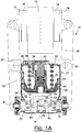
- a preferred example embodiment of a compact brake unit wholly indicated with reference numeral 10, for a disc brake 12 of a vehicle particularly intended to travel on rails.
- the braking unit 10 firstly comprises a pair of jaws 14, provided with relative friction gaskets 16, intended to rub on the two opposite surfaces of the disc 12 that can be mounted on the axle or else on the wheel of the vehicle.
- the jaws 14 are hinged at one of the ends of a pair of levers 18, in turn pivoted on respective hinges 20 fixedly connected to the main body of the braking unit 10, and they are actuated by a braking force motor 22, in this case a pneumatic or hydraulic actuator cylinder.
- the assembly consisting of the jaws 14, the friction gaskets 16 and the pair of opposite levers 18 forms the actual brake pincer of the braking unit 10 according to the present invention.
- the pneumatic or hydraulic actuator cylinder 22 in the embodiment that foresees the use of the braking unit 10 of the invention both as a service brake and as a parking brake ( figure 1A ), is divided into two chambers by a partition element 24.
- the piston 26 for service braking is located in one of the chambers and the piston 28 for parking braking is in the other, coaxial to the aforementioned piston 26.
- the mechanism that generates the force for the parking brake comprises a spring 30, housed between the piston 28 for parking braking and a cover 32, whereas the group that transfers the force from the spring 30 to the piston 26 for service braking is made up of a gearing-trapezoidal screw 34, an axial bearing 36, an intermediate component 38, a locking lever 40, a cover 42 and a pin 44.
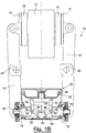
- the actuator cylinder 22 houses a single piston 26 for service braking and is defined by a wall 46.
- the pistons 26 and 28 act upon a thrusting mechanism 48 to amplify the force inserted inside the actuator cylinder 22.
- a mechanism or linkage 48 illustrated in figures 1A and 1B and, in partial detail, in figure 3 based upon a first example embodiment thereof, substantially comprises a first lever 50, arranged perpendicular to the direction A of movement of the pistons 26 and 28 and on which the piston 26 acts resting against it as a service brake, and a pair of levers 52 hinged, at a first end thereof 54, on the opposite ends of the lever 50.
- each lever 52 is further hinged, at a second end 56, on a further pair of levers 58, the pair of levers 58 finally being pivoted, by means of pins 60, on a support plate 62 integral with the main body of the actuator cylinder 22.
- the pair of levers 58 is therefore able to transfer the force transmitted by the piston 26 or, if present, by the piston 28 to clutches 64, each connected to the corresponding lever 58 by means of a suitable pin 66.
- the thrusting mechanism 48' comprises a wedge-shaped element 92 that extends substantially along the direction A of movement of the pistons 26 and 28 and on the base of which 94 the piston 26 for service braking acts resting against it.
- the wedge-shaped element 92 cooperates with a pair of opposite bearings 96 with respect to the axis A, hinged to the clutches 64 and in contact with suitable guides 98 integral with the main body of the actuator cylinder 22.
- the wedge-shaped element 92 transfers and amplifies the force transmitted by the piston 26 or, if present, by the piston 28 to the bearings 96 and, consequently, to the clutches 64.
- the function of the clutches 64 is to send the braking force generated inside the actuator cylinder 22 to the brake pincer, in particular to the ends of the levers 18 opposite those on which the jaws 14 are fixedly connected.
- the group 68 for automatically regulating the clearances that form between the friction gaskets 16 and the brake disc 12, for example due to the wearing of the gaskets 16 themselves consists of two clearance regulation mechanisms 70, or wear compensators, positioned symmetrically with respect to the longitudinal axis A of the pistons 26 and 28 and able to be operated in the direction of the axis B, perpendicular to the aforementioned axis A.
- each clearance regulation mechanism 70 comprises an internal thread 76 capable of receiving the braking force of each clutch 64, a trapezoidal screw 78 operatively connected to the internal thread 76 and to the corresponding lever 18, an axial bearing 72 and an elastic ring 74, coaxial and arranged between the clutch 64 and the internal thread 76, and a coil spring 80 that acts upon each trapezoidal screw 78.
- the internal threads 76 and the respective trapezoidal screws 78 are connected together by a multi-start thread.
- each clearance regulation mechanism 70 is also equipped, in the portion facing towards the middle axis A of the braking unit 10, with respective opposite locking bushes 82 and 84, which act in abutment against the inner threads 76 pushed by a coil spring 90 arranged in compression between them.
- the locking bushes 82 and 84 are then interconnected by means of a regulation screw 86 and a toothed bush 88.
- the toothed bush 88 can be operated to regulate the distance M between the head of the regulation screw 86. and the front part of one of the locking bushes 82, such a distance M being able to be set according to the distance that one wishes to keep between the disc 12 and the friction gaskets 16 in the rest conditions of the braking unit 10.
- the actuation force of the service braking is generated by the action of compressed air or, alternatively, of a pressurised hydraulic fluid, which enters into the portion of the actuator cylinder 22 intended for the service brake through a suitable inlet hole (not shown).
- the air, or the hydraulic fluid acts upon the piston 26 for service braking, which advances inside the cylinder 22 compressing the lever 50 of the thrusting linkage for amplifying the force 48.
- the braking force transmitted by the piston 26 to the lever 50 is divided into the two components F acting on the levers 52 and, from these and by means of the further two levers 58, such a force is amplified and transferred, through the pins 66 and in the direction of the axis B (F1 in figure 3 ) perpendicular to that of the aforementioned components F, to the clutches 64.
- the braking force amplification function is, on the other hand, left to the wedge-shaped mechanism 48'.
- the braking force transmitted by the piston 26 to the wedge-shaped element 92 moves the latter along the axis A towards the bearings 96.
- Such a wedge-shaped element 92 thus acts upon the bearings 96 to amplify, with variable magnitude according to the angle of inclination of the wedge 92 itself, the braking force so as to transfer it, through the reaction of the axial locking discs 100 of the bearings 96 against the guides 98 integral with the base plate of the actuator cylinder 22, to the clutches 64 in the direction of the axis B (F1 in figure 5 ) perpendicular to the direction A along which the piston 26 moves.
- the parking brake itself is reloaded through the inlet of compressed air, or of pressurised hydraulic fluid, in the portion of the cylinder 22 intended for the parking brake.
- the air, or the pressurised hydraulic fluid pushes the piston 28 for parking braking, which compresses the spring 30.
- the gearing-trapezoidal screw 34 which is connected through a multi-start threading with the piston 28 itself, carries out a rotation.
- the gearing-trapezoidal screw 34 and the locking lever 40 functionally represent a unidirectional anti-rotation mechanism so that, when the gearing-trapezoidal screw 34 rotates, a certain number of its teeth are ridden over by the locking lever 40.
- the actuation force of the parking brake is generated by the spring 30 and takes place by discharging the compressed air, or the pressurised hydraulic fluid, through a suitable outlet hole (not shown), from the portion of the cylinder 22 intended for the parking brake.
- the gearing-trapezoidal screw 34 transfers the force to the piston 26 for service braking, thus actuating the parking brake of the vehicle in the same way in which the normal service braking described previously takes place.
- the braking force is transferred to the thrusting mechanism for amplifying the force 48 or 48' and, from it, reaches the brake pincer directly through the two opposite clearance recovery and regulation mechanisms 70.
- the braking force is always transferred to the thrusting mechanism for amplifying the force 48 or 48' solely through the piston 26 for service braking.
- the parking brake itself By feeding the portion of the cylinder 22 intended for the parking brake with air or pressurised hydraulic fluid, the parking brake itself can finally be decoupled, thus placing the vehicle in the normal travel conditions.
- the braking force that the clutches 64 receive from the thrusting mechanism for amplifying the force 48 or 48' follows the direction of the arrows S of figure 2 .
- the inner threadings 76 of each clearance regulation mechanism 70 begin to translate in the same direction.
- the locking bushes 82 and 84 also begin to separate from one another.
- the compact unit for generating braking force particularly for railway vehicles or vehicles on rails, according to the present invention achieves the purposes outlined earlier, transferring the braking force itself, increased by means of the amplification mechanisms described above, directly to the two clearance recovery mechanisms connected to the brake pincer, at the ends of which are the friction gaskets that act on the disc.
- An important advantage due to the use of two opposite recovery mechanisms is the fact that, working independently but being made integral with each other by simple elements that allow their relative movements in space, they autonomously compensate the transversal movements of the braking unit, integral with the carriage or with the frame of the vehicle, with respect to the brake disc, fixed onto the axle or onto the wheel, and they do not need an additional device suitable for preventing the undesired application of the clearance recovery mechanism in the case of transversal movement of the carriage during normal travel of the vehicle itself.
- the undesired application of the clearance recovery mechanism is, on the other hand, prevented through complex assemblies based upon mechanical shafts or relays.
- the invention is therefore aimed at maintaining high performance, at the same time reducing the manufacturing and maintenance costs, thanks to the presence of a smaller number of components.
- the compact disc-brake unit for vehicles on rails of the present invention thus conceived is also able to be integrated and personalised according to the client's requirements with all devices normally used in the field of rail travel, like for example manual or pneumatic unlocking of the parking brake, anticompound valve (selector valve that avoids the simultaneous action of the service brake and the parking brake), sensor for indicating the state of the parking brake and/or valve X (optional device designed for cylinders with spring-actuated parking brake with the purpose of preventing the incorrect application of the parking brake, while the vehicle is travelling, caused by the lack of pressurised air in the cylinder chamber of the parking brake following a malfunction, for example when the pneumatic supply pipes breaks.
- anticompound valve switch valve that avoids the simultaneous action of the service brake and the parking brake
- sensor for indicating the state of the parking brake and/or valve X optionally device designed for cylinders with spring-actuated parking brake with the purpose of preventing the incorrect application of the parking brake, while the vehicle is travelling, caused by the lack of pressurised
- the compact disc-brake unit for vehicles on rails of the present invention thus conceived can in any case undergo numerous modification and variants, all of which are covered by the same inventive concept.
Claims (9)
- Scheibenbremseinheit (10) für Fahrzeuge auf Schienen, umfassend eine Bremszange, die aus einem Paar Backen (14) besteht, die mit relativen Reibungsdichtungen (16) versehen sind, welche dazu bestimmt sind, an den beiden gegenüberliegenden Oberflächen einer Scheibe (12) zu reiben, wobei die Backen (14) an einem der Enden eines Paares von Hebeln (18) angelenkt sind, wobei die Hebel (18) an entsprechenden Scharnieren (20) schwenkbar sind, die fest mit dem Hauptkörper der Bremseinheit (10) verbunden sind und von einem Bremskraftmotor (22) betätigt werden, der mit mindestens einem ersten Kolben (26) versehen ist, der sich mit wechselnder Bewegung entlang einer ersten Achse (A) bewegt, wobei die Bremseinheit (10) auch eine Gruppe (68) zum automatischen Regeln der Spiele zwischen den Reibungsdichtungen (16) und der Scheibe (12) umfasst, wobei der Kolben (26) die Bremskraft auf einen Schubmechanismus (48, 48') zum Verstärken und Übertragen der Bremskraft auf die Gruppe (68) zum automatischen Regeln der Spiele überträgt, und die Gruppe (68) zum automatischen Regeln der Spiele, das die Bremskraft entlang einer zweiten Achse (B) senkrecht zu der ersten Achse (A) zu den Enden der Hebel (18) gegenüber den Enden, an denen die Backen (14) angelenkt sind, überträgt, wobei die Gruppe (68) zum automatischen Regeln der Spiele entlang der zweiten Achse (B) liegt und zwei Spielregulierungsmechanismen (70) umfasst, die symmetrisch in Bezug auf die erste Achse (A) angeordnet sind und entlang der zweiten Achse (B) betrieben werden, wobei jeder Spielregulierungsmechanismus (70)- ein Innengewinde (76) umfasst, das die Bremskraft von dem Schubmechanismus (48, 48') aufnehmen kann;dadurch gekennzeichnet, dass jeder Spielregulierungsmechanismus (70) Folgendes umfasst:- eine Trapezschraube (78), die mit dem Innengewinde (76) und dem entsprechenden Hebel (18) wirkverbunden ist,- eine Schraubenfeder (80), die auf jede der Trapezschrauben (78) wirkt, und- jeweilige gegenüberliegende Verriegelungsbuchsen (82, 84), die in dem Abschnitt der Spielregelungsmechanismen (70) angeordnet sind, der der ersten Achse (A) zugewandt ist,wobei die Verriegelungsbuchsen (82, 84) gegen das Innengewinde (76) anliegend wirken und von einer Feder (90) gedrückt werden, die zwischen den Verriegelungsbuchsen (82, 84) zusammengedrückt ist, und wobei die Verriegelungsbuchsen (82, 84) mittels einer Regulierschraube (86) und einer Zahnbuchse (88) verknüpft sind.
- Bremseinheit (10) nach Anspruch 1, dadurch gekennzeichnet, dass der Bremskraftmotor (22) mit mindestens einem zweiten Kolben (28) zum Feststellbremsen koaxial zum ersten Kolben (26) versehen ist.
- Bremseinheit (10) nach Anspruch 2, dadurch gekennzeichnet, dass der zweite Kolben (28) die Betätigungskraft der Feststellbremse durch den ersten Kolben (26) auf den Schubmechanismus (48, 48') überträgt.
- Bremseinheit (10) nach Anspruch 1, dadurch gekennzeichnet, dass der Schubmechanismus (48) einen ersten Hebel (50) umfasst, der senkrecht zu der ersten Achse (A) angeordnet ist und auf den der Kolben (26) wirkt und an dem er anliegt, ein Paar angelenkte Hebel (52), an einem ersten Ende (54) davon, an den gegenüberliegenden Enden des Hebels (50) und an einem zweiten Ende (56) davon, an einem weiteren Paar Hebel (58), wobei jeder der Hebel (58) die Bremskraft auf den entsprechenden Spielregulierungsmechanismus (70) entlang der zweiten Achse (B) überträgt.
- Bremseinheit (10) nach Anspruch 4, dadurch gekennzeichnet, dass das Paar Hebel (58) mittels entsprechender Stifte (60) auf einer Trägerplatte (62) verschwenkt ist, die mit dem Hauptkörper des Bremskraftmotors (22) integral ist.
- Bremseinheit (10) nach Anspruch 4, dadurch gekennzeichnet, dass jeder der Hebel (58) die Bremskraft mittels einer Kupplung (64), die über mindestens einen Bolzen (66) mit dem entsprechenden Hebel (58) verbunden ist, auf den entsprechenden Spielregulierungsmechanismus (70) überträgt.
- Bremseinheit (10) nach Anspruch 1, dadurch gekennzeichnet, dass der Schubmechanismus (48') mindestens ein keilförmiges Element (92) umfasst, das sich im Wesentlichen entlang der ersten Achse (A) erstreckt und auf dessen Basis (94) der an ihr anliegende Kolben (26) wirkt, wobei das keilförmige Element (92) mit mindestens einem Paar Lager (96) zusammenwirkt, gegenüber der ersten Achse (A) und ausgestattet mit relativen axialen Verriegelungsscheiben (100) in Kontakt mit entsprechenden Führungen (98), die mit dem Hauptkörper des Bremskraftmotors (22) integral sind, um die Bremskraft auf den entsprechenden Spielregulierungsmechanismus (70) entlang der zweiten Achse (B) zu übertragen.
- Bremseinheit (10) nach Anspruch 7, dadurch gekennzeichnet, dass jedes der Lager (96) die Bremskraft mittels einer Kupplung (64), an der jedes der Lager (96) angelenkt ist, auf den entsprechenden Spielregulierungsmechanismus (70) überträgt.
- Bremseinheit (10) nach Anspruch 1, dadurch gekennzeichnet, dass die Zahnbuchse (88) betätigbar ist, um den Abstand (M) zwischen dem Kopf der Regelschraube (86) und dem vorderen Teil einer der Verriegelungsbuchsen (82) zu regeln, wobei der Abstand (M) entsprechend dem Abstand eingestellt werden kann, den man zwischen der Scheibe (12) und den Reibungsdichtungen (16) in Ruhezuständen der Bremseinheit (10) einhalten möchte.
Applications Claiming Priority (2)
| Application Number | Priority Date | Filing Date | Title |
|---|---|---|---|
| IT001513A ITMI20061513A1 (it) | 2006-07-31 | 2006-07-31 | Unita' frenante compatta a disco per veicoli su rotaia |
| PCT/IB2007/002281 WO2008015569A2 (en) | 2006-07-31 | 2007-07-30 | Compact disc-brake unit for vehicles on rails |
Publications (2)
| Publication Number | Publication Date |
|---|---|
| EP2047134A2 EP2047134A2 (de) | 2009-04-15 |
| EP2047134B1 true EP2047134B1 (de) | 2018-11-28 |
Family
ID=38997531
Family Applications (1)
| Application Number | Title | Priority Date | Filing Date |
|---|---|---|---|
| EP07804735.4A Active EP2047134B1 (de) | 2006-07-31 | 2007-07-30 | Kompakte scheibenbremseneinheit für schienenfahrzeuge |
Country Status (9)
| Country | Link |
|---|---|
| US (1) | US8794393B2 (de) |
| EP (1) | EP2047134B1 (de) |
| JP (1) | JP5273870B2 (de) |
| KR (1) | KR101237672B1 (de) |
| CN (1) | CN101523074B (de) |
| AU (1) | AU2007280090B2 (de) |
| IT (1) | ITMI20061513A1 (de) |
| RU (1) | RU2431067C2 (de) |
| WO (1) | WO2008015569A2 (de) |
Families Citing this family (36)
| Publication number | Priority date | Publication date | Assignee | Title |
|---|---|---|---|---|
| GB0817230D0 (en) * | 2008-09-19 | 2008-10-29 | Meritor Heavy Vehicle Braking | A parking brake mechanism |
| JP5465788B2 (ja) * | 2009-11-30 | 2014-04-09 | ヒルマー インダストリーズ リミテッド | 垂直引込式レールクランプ |
| CN101734258B (zh) * | 2010-01-11 | 2012-05-23 | 重庆大学 | 一种有轨传送车制动装置 |
| TWI422757B (zh) * | 2010-05-27 | 2014-01-11 | Nabtesco Corp | Brake cylinder device and disc brake device |
| KR101006061B1 (ko) * | 2010-06-08 | 2011-01-06 | 유진기공산업주식회사 | 철도 차량용 디스크 브레이크 장치 |
| TW201206946A (en) | 2010-07-15 | 2012-02-16 | Bristol Myers Squibb Co | Compounds for the reduction of beta-amyloid production |
| EP2784341B1 (de) | 2011-11-25 | 2016-09-21 | Nabtesco Corporation | Bremszylindervorrichtung und scheibenbremsenvorrichtung |
| JP5880003B2 (ja) * | 2011-12-14 | 2016-03-08 | 新日鐵住金株式会社 | 鉄道車両用キャリパブレーキ装置 |
| DE102012107362A1 (de) * | 2012-08-10 | 2014-02-13 | Rg Mechatronics Gmbh | Reibungsbremse mit wenigstens einem an einem Festkörpergelenk gelagerten Bremshebel |
| US9522684B2 (en) * | 2013-06-19 | 2016-12-20 | Nippon Steel & Sumitomo Metal Corporation | Caliper brake device for railway vehicle |
| JP6393521B2 (ja) * | 2014-05-27 | 2018-09-19 | Kyb株式会社 | ブレーキ装置 |
| KR101477650B1 (ko) * | 2014-06-11 | 2014-12-30 | 재단법인대구경북과학기술원 | 마모보상 기능을 갖는 전기기계브레이크 |
| JP6277076B2 (ja) * | 2014-07-18 | 2018-02-07 | Kyb株式会社 | ブレーキ装置 |
| US10260578B2 (en) * | 2014-08-18 | 2019-04-16 | Kyb Corporation | Parking brake unit |
| JP6295167B2 (ja) * | 2014-08-18 | 2018-03-14 | Kyb株式会社 | ブレーキ装置 |
| US9954287B2 (en) | 2014-11-20 | 2018-04-24 | At&T Intellectual Property I, L.P. | Apparatus for converting wireless signals and electromagnetic waves and methods thereof |
| US9694833B2 (en) * | 2014-12-04 | 2017-07-04 | Akebono Brake Industry Co., Ltd. | Disk brake and disk brake for railway vehicle |
| US9956971B2 (en) * | 2014-12-16 | 2018-05-01 | Faiveley Transport Amiens | Rail vehicle braking system and braking method for a rail vehicle comprising such a system |
| CN109808728B (zh) * | 2014-12-31 | 2020-10-09 | 法维莱运输亚眠公司 | 用于铁路车辆的铁路制动系统 |
| JP6438327B2 (ja) * | 2015-03-11 | 2018-12-12 | Kyb株式会社 | ブレーキ装置 |
| CN104912966B (zh) * | 2015-05-29 | 2018-07-17 | 洛阳中重自动化工程有限责任公司 | 一种用于大型磨机的钳式制动器 |
| DE102015219058B3 (de) * | 2015-09-29 | 2017-04-13 | Kes Keschwari Electronic Systems Gmbh & Co. Kg | Bremszylinder mit integriertem Verschleißnachsteller für Schienenfahrzeuge |
| FR3048399B1 (fr) * | 2016-03-04 | 2018-04-13 | Faiveley Transport Amiens | Systeme de freinage ferroviaire pour vehicule ferroviaire et procede de freinage d'un vehicule ferroviaire comportant un tel systeme |
| DE102016205961A1 (de) | 2016-04-05 | 2017-10-05 | Kes Keschwari Electronic Systems Gmbh & Co. Kg | Bremse mit symmetrischem Verschleißnachsteller |
| EP3228897B1 (de) | 2016-04-05 | 2018-04-25 | KES Keschwari Electronic Systems GmbH & Co. KG | Bremse mit symmetrischem verschleissnachsteller |
| RS63973B1 (sr) * | 2016-06-03 | 2023-03-31 | Drillform Technical Services Ltd | Samopojačavajuća bezbednosna kočnica |
| ES2733451T3 (es) | 2016-08-25 | 2019-11-29 | Dellner Brakes Ab | Un dispositivo de frenado de tipo palanca |
| IT201600113666A1 (it) * | 2016-11-10 | 2018-05-10 | Jiangxi Huawu Brake Co Ltd | Attuatore freno compatto per veicoli ferroviari |
| CN106696716A (zh) * | 2017-01-16 | 2017-05-24 | 重庆三峡学院 | 一种电动车用线控制动单元 |
| EP3560791B1 (de) | 2018-04-27 | 2020-07-29 | Jiangxi Huawu Brake Co., Ltd. | Kompakter bremsaktuator für schienenfahrzeuge |
| US20190337539A1 (en) * | 2018-05-07 | 2019-11-07 | Jiangxi Huawu Brake Co., Ltd. | Compact brake actuator for railway vehicles |
| CN110454528B (zh) * | 2018-05-08 | 2021-01-19 | 江西华伍制动器股份有限公司 | 用于轨道车辆的紧凑的制动驱动装置 |
| DE102019101341B4 (de) * | 2019-01-18 | 2020-07-30 | Knorr-Bremse Systeme für Schienenfahrzeuge GmbH | Verschleißnachsteller einer Kompakt-Bremszangeneinheit, und Kompakt-Bremszangeneinheit mit einem solchen Verschleißnachsteller |
| CN114364593A (zh) * | 2019-04-30 | 2022-04-15 | 希尔玛工业有限公司 | 具有可旋转制动蹄的轨道夹具 |
| CN110410437B (zh) * | 2019-07-22 | 2024-02-06 | 嘉兴盛鼎机械有限公司 | 具有平衡阀结构的制动气室 |
| KR102251095B1 (ko) * | 2020-09-21 | 2021-05-11 | 임현우 | 쐐기형 브레이크 |
Family Cites Families (24)
| Publication number | Priority date | Publication date | Assignee | Title |
|---|---|---|---|---|
| GB525328A (en) * | 1939-02-17 | 1940-08-26 | Arthur George Taylor | Improvements in and relating to actuating means for brake shoes |
| US2911070A (en) * | 1956-04-20 | 1959-11-03 | American Steel Foundries | Rotor brake |
| US3148749A (en) * | 1962-08-03 | 1964-09-15 | Amsted Ind Inc | Rotor brake |
| US3334328A (en) * | 1963-07-01 | 1967-08-01 | Texas Instruments Inc | Acoustical radiating antenna |
| US3334709A (en) * | 1965-01-06 | 1967-08-08 | Eaton Yale & Towne | Automatic brake adjuster |
| GB1418681A (en) * | 1972-03-03 | 1975-12-24 | Girling Ltd | Internal shoedrum brakes |
| DE2235819C3 (de) * | 1972-07-21 | 1981-07-23 | Fritz Wagner, Maschinenfabrik Gmbh & Co Kg, 6781 Schweix | Vorrichtung zur Erzeugung von Tiefenprägungen in Schuhschäften |
| US3926094A (en) * | 1973-07-02 | 1975-12-16 | Midland Ross Corp | Air operated spring brake |
| US3986584A (en) * | 1975-03-20 | 1976-10-19 | Westinghouse Air Brake Company | Fail-safe disc brake with spring actuated slack adjuster |
| GB1509398A (en) * | 1975-10-03 | 1978-05-04 | Girling Ltd | Automatic slack adjusters for vehicle brakes |
| DE2607348C3 (de) * | 1976-02-24 | 1983-01-13 | Helmut 5909 Burbach-Niederdresselndorf Henrich | Teilbelag-Scheibenbremse |
| DE2903493A1 (de) * | 1979-01-30 | 1980-07-31 | Siemens Ag | Verfahren und anordnung zur fehlerortung und ueberwachung einer nachrichtenverbindung |
| US4308937A (en) * | 1979-12-04 | 1982-01-05 | Johnson Norman A | Self-aligning clamping apparatus |
| US4416356A (en) * | 1980-09-27 | 1983-11-22 | Automotive Products Limited | Hydraulic wheel cylinder assemblies and drum brakes incorporating same |
| JPS58153733U (ja) * | 1982-04-10 | 1983-10-14 | 日産自動車株式会社 | デイスクブレ−キ |
| DE3326374A1 (de) * | 1983-07-21 | 1985-01-31 | Knorr-Bremse GmbH, 8000 München | Bremsgestaenge fuer fahrzeugreibungsbremsen |
| GB8324942D0 (en) * | 1983-09-17 | 1983-10-19 | Lucas Ind Plc | Actuator assemblies for vehicle brakes |
| FR2554194B1 (fr) * | 1983-10-28 | 1986-01-17 | Dba | Moteur de frein a reglage automatique |
| EP0210788A1 (de) * | 1985-07-23 | 1987-02-04 | LUCAS INDUSTRIES public limited company | Automatische Nachstellvorrichtung |
| FR2679612A1 (fr) * | 1991-07-22 | 1993-01-29 | Jimecal | Dispositif de freinage a machoires pour vehicules, notamment pour poids lourds. |
| JP2001050319A (ja) * | 1999-08-06 | 2001-02-23 | Nisshinbo Ind Inc | ブレーキのシリンダ装置 |
| DE19945702A1 (de) * | 1999-09-23 | 2001-04-19 | Knorr Bremse Systeme | Zuspannvorrichtung für eine Fahrzeugbremse |
| JP2003156087A (ja) * | 2001-11-22 | 2003-05-30 | Nisshinbo Ind Inc | ブレーキシリンダ装置 |
| DE102007032966B4 (de) | 2007-07-16 | 2009-11-12 | Knorr-Bremse Systeme für Schienenfahrzeuge GmbH | Lagerungsanordnung für Exzenterwellen |
-
2006
- 2006-07-31 IT IT001513A patent/ITMI20061513A1/it unknown
-
2007
- 2007-07-30 CN CN2007800363501A patent/CN101523074B/zh active Active
- 2007-07-30 JP JP2009522364A patent/JP5273870B2/ja active Active
- 2007-07-30 WO PCT/IB2007/002281 patent/WO2008015569A2/en active Application Filing
- 2007-07-30 US US12/309,725 patent/US8794393B2/en active Active
- 2007-07-30 EP EP07804735.4A patent/EP2047134B1/de active Active
- 2007-07-30 KR KR1020097003094A patent/KR101237672B1/ko active IP Right Grant
- 2007-07-30 RU RU2009103558/11A patent/RU2431067C2/ru active
- 2007-07-30 AU AU2007280090A patent/AU2007280090B2/en active Active
Non-Patent Citations (1)
| Title |
|---|
| None * |
Also Published As
| Publication number | Publication date |
|---|---|
| CN101523074A (zh) | 2009-09-02 |
| JP5273870B2 (ja) | 2013-08-28 |
| US8794393B2 (en) | 2014-08-05 |
| KR20090034978A (ko) | 2009-04-08 |
| CN101523074B (zh) | 2012-03-21 |
| EP2047134A2 (de) | 2009-04-15 |
| JP2009545712A (ja) | 2009-12-24 |
| WO2008015569A3 (en) | 2008-05-29 |
| KR101237672B1 (ko) | 2013-02-26 |
| RU2009103558A (ru) | 2010-09-10 |
| AU2007280090A1 (en) | 2008-02-07 |
| US20100044165A1 (en) | 2010-02-25 |
| ITMI20061513A1 (it) | 2008-02-01 |
| WO2008015569A2 (en) | 2008-02-07 |
| AU2007280090B2 (en) | 2011-11-03 |
| RU2431067C2 (ru) | 2011-10-10 |
Similar Documents
| Publication | Publication Date | Title |
|---|---|---|
| EP2047134B1 (de) | Kompakte scheibenbremseneinheit für schienenfahrzeuge | |
| KR101578232B1 (ko) | 가변 기어 비를 가진 동력 전달식 트랜스미션을 구비한 조합형 실린더 | |
| US5582273A (en) | Compressed-air disc brake | |
| US7073636B2 (en) | Disk brake with mechanical self-boosting | |
| US20110005871A1 (en) | Pneumatically Actuated Disc Brake with Actuation Tappet | |
| EP1610024B1 (de) | Scheibenbremse mit einem Bremsmechanismus | |
| US7694784B2 (en) | Adjusting apparatus for a pneumatically actuated disc brake | |
| US7950502B2 (en) | Electromechanically actuated disc brake with guide plate | |
| US5495921A (en) | Single actuator truck mount brake system | |
| US20040262101A1 (en) | Disk brake with self-boosting | |
| EP1160478A2 (de) | Bremsmechanismus und Verfahren zur Steuerung der Kraftverstärkung | |
| US3498421A (en) | Hydraulic disk brake with mechanical actuating means | |
| HU221836B1 (hu) | Fékműködtető szerkezet | |
| CA2003809C (en) | Disc brake | |
| US10570970B2 (en) | Disc brake for a commercial vehicle | |
| US3337009A (en) | Brake system with twin fluid-supply networks | |
| JP2022532804A (ja) | 低剛性の弾性リザーブを有するアクチュエータを備えた電気機械式ドラムブレーキ | |
| US3482657A (en) | Disk brake with mechanical actuator and adjusting means | |
| US6799662B1 (en) | Spring-actuated, hydraulically releasable brakes | |
| AU2020321464A1 (en) | Railway braking system comprising brake rigging, and rail vehicle equipped with such a system | |
| GB2153461A (en) | Disc brake adjustment | |
| USRE28603E (en) | Load transmitting struts | |
| AU701399B2 (en) | Single actuator truck mount brake system | |
| US20120124990A1 (en) | Support cylinder for a self-energizing hydraulic brake | |
| SE507135C2 (sv) | Anordning vid skivbromsar för motorfordon |
Legal Events
| Date | Code | Title | Description |
|---|---|---|---|
| PUAI | Public reference made under article 153(3) epc to a published international application that has entered the european phase |
Free format text: ORIGINAL CODE: 0009012 |
|
| 17P | Request for examination filed |
Effective date: 20090126 |
|
| AK | Designated contracting states |
Kind code of ref document: A2 Designated state(s): AT BE BG CH CY CZ DE DK EE ES FI FR GB GR HU IE IS IT LI LT LU LV MC MT NL PL PT RO SE SI SK TR |
|
| AX | Request for extension of the european patent |
Extension state: HR MK RS |
|
| 17Q | First examination report despatched |
Effective date: 20090605 |
|
| RAX | Requested extension states of the european patent have changed |
Extension state: HR Payment date: 20090126 Extension state: RS Payment date: 20090126 Extension state: MK Payment date: 20090126 |
|
| STAA | Information on the status of an ep patent application or granted ep patent |
Free format text: STATUS: EXAMINATION IS IN PROGRESS |
|
| GRAP | Despatch of communication of intention to grant a patent |
Free format text: ORIGINAL CODE: EPIDOSNIGR1 |
|
| STAA | Information on the status of an ep patent application or granted ep patent |
Free format text: STATUS: GRANT OF PATENT IS INTENDED |
|
| INTG | Intention to grant announced |
Effective date: 20180620 |
|
| GRAS | Grant fee paid |
Free format text: ORIGINAL CODE: EPIDOSNIGR3 |
|
| GRAA | (expected) grant |
Free format text: ORIGINAL CODE: 0009210 |
|
| STAA | Information on the status of an ep patent application or granted ep patent |
Free format text: STATUS: THE PATENT HAS BEEN GRANTED |
|
| AK | Designated contracting states |
Kind code of ref document: B1 Designated state(s): AT BE BG CH CY CZ DE DK EE ES FI FR GB GR HU IE IS IT LI LT LU LV MC MT NL PL PT RO SE SI SK TR |
|
| AX | Request for extension of the european patent |
Extension state: HR MK RS |
|
| RAP1 | Party data changed (applicant data changed or rights of an application transferred) |
Owner name: POLI COSTRUZIONE MATERIALI TRAZIONE S.R.L., SHORTL |
|
| REG | Reference to a national code |
Ref country code: GB Ref legal event code: FG4D |
|
| REG | Reference to a national code |
Ref country code: CH Ref legal event code: EP |
|
| REG | Reference to a national code |
Ref country code: AT Ref legal event code: REF Ref document number: 1070591 Country of ref document: AT Kind code of ref document: T Effective date: 20181215 |
|
| REG | Reference to a national code |
Ref country code: DE Ref legal event code: R096 Ref document number: 602007056987 Country of ref document: DE |
|
| REG | Reference to a national code |
Ref country code: IE Ref legal event code: FG4D |
|
| REG | Reference to a national code |
Ref country code: SE Ref legal event code: TRGR |
|
| REG | Reference to a national code |
Ref country code: NL Ref legal event code: MP Effective date: 20181128 |
|
| REG | Reference to a national code |
Ref country code: LT Ref legal event code: MG4D |
|
| PG25 | Lapsed in a contracting state [announced via postgrant information from national office to epo] |
Ref country code: LV Free format text: LAPSE BECAUSE OF FAILURE TO SUBMIT A TRANSLATION OF THE DESCRIPTION OR TO PAY THE FEE WITHIN THE PRESCRIBED TIME-LIMIT Effective date: 20181128 Ref country code: BG Free format text: LAPSE BECAUSE OF FAILURE TO SUBMIT A TRANSLATION OF THE DESCRIPTION OR TO PAY THE FEE WITHIN THE PRESCRIBED TIME-LIMIT Effective date: 20190228 Ref country code: IS Free format text: LAPSE BECAUSE OF FAILURE TO SUBMIT A TRANSLATION OF THE DESCRIPTION OR TO PAY THE FEE WITHIN THE PRESCRIBED TIME-LIMIT Effective date: 20190328 Ref country code: ES Free format text: LAPSE BECAUSE OF FAILURE TO SUBMIT A TRANSLATION OF THE DESCRIPTION OR TO PAY THE FEE WITHIN THE PRESCRIBED TIME-LIMIT Effective date: 20181128 Ref country code: LT Free format text: LAPSE BECAUSE OF FAILURE TO SUBMIT A TRANSLATION OF THE DESCRIPTION OR TO PAY THE FEE WITHIN THE PRESCRIBED TIME-LIMIT Effective date: 20181128 |
|
| PG25 | Lapsed in a contracting state [announced via postgrant information from national office to epo] |
Ref country code: PT Free format text: LAPSE BECAUSE OF FAILURE TO SUBMIT A TRANSLATION OF THE DESCRIPTION OR TO PAY THE FEE WITHIN THE PRESCRIBED TIME-LIMIT Effective date: 20190328 Ref country code: GR Free format text: LAPSE BECAUSE OF FAILURE TO SUBMIT A TRANSLATION OF THE DESCRIPTION OR TO PAY THE FEE WITHIN THE PRESCRIBED TIME-LIMIT Effective date: 20190301 |
|
| PG25 | Lapsed in a contracting state [announced via postgrant information from national office to epo] |
Ref country code: NL Free format text: LAPSE BECAUSE OF FAILURE TO SUBMIT A TRANSLATION OF THE DESCRIPTION OR TO PAY THE FEE WITHIN THE PRESCRIBED TIME-LIMIT Effective date: 20181128 |
|
| PG25 | Lapsed in a contracting state [announced via postgrant information from national office to epo] |
Ref country code: CZ Free format text: LAPSE BECAUSE OF FAILURE TO SUBMIT A TRANSLATION OF THE DESCRIPTION OR TO PAY THE FEE WITHIN THE PRESCRIBED TIME-LIMIT Effective date: 20181128 Ref country code: DK Free format text: LAPSE BECAUSE OF FAILURE TO SUBMIT A TRANSLATION OF THE DESCRIPTION OR TO PAY THE FEE WITHIN THE PRESCRIBED TIME-LIMIT Effective date: 20181128 Ref country code: PL Free format text: LAPSE BECAUSE OF FAILURE TO SUBMIT A TRANSLATION OF THE DESCRIPTION OR TO PAY THE FEE WITHIN THE PRESCRIBED TIME-LIMIT Effective date: 20181128 |
|
| REG | Reference to a national code |
Ref country code: DE Ref legal event code: R097 Ref document number: 602007056987 Country of ref document: DE |
|
| PG25 | Lapsed in a contracting state [announced via postgrant information from national office to epo] |
Ref country code: EE Free format text: LAPSE BECAUSE OF FAILURE TO SUBMIT A TRANSLATION OF THE DESCRIPTION OR TO PAY THE FEE WITHIN THE PRESCRIBED TIME-LIMIT Effective date: 20181128 Ref country code: RO Free format text: LAPSE BECAUSE OF FAILURE TO SUBMIT A TRANSLATION OF THE DESCRIPTION OR TO PAY THE FEE WITHIN THE PRESCRIBED TIME-LIMIT Effective date: 20181128 Ref country code: SK Free format text: LAPSE BECAUSE OF FAILURE TO SUBMIT A TRANSLATION OF THE DESCRIPTION OR TO PAY THE FEE WITHIN THE PRESCRIBED TIME-LIMIT Effective date: 20181128 |
|
| PLBE | No opposition filed within time limit |
Free format text: ORIGINAL CODE: 0009261 |
|
| STAA | Information on the status of an ep patent application or granted ep patent |
Free format text: STATUS: NO OPPOSITION FILED WITHIN TIME LIMIT |
|
| PG25 | Lapsed in a contracting state [announced via postgrant information from national office to epo] |
Ref country code: SI Free format text: LAPSE BECAUSE OF FAILURE TO SUBMIT A TRANSLATION OF THE DESCRIPTION OR TO PAY THE FEE WITHIN THE PRESCRIBED TIME-LIMIT Effective date: 20181128 |
|
| 26N | No opposition filed |
Effective date: 20190829 |
|
| PG25 | Lapsed in a contracting state [announced via postgrant information from national office to epo] |
Ref country code: MC Free format text: LAPSE BECAUSE OF FAILURE TO SUBMIT A TRANSLATION OF THE DESCRIPTION OR TO PAY THE FEE WITHIN THE PRESCRIBED TIME-LIMIT Effective date: 20181128 |
|
| REG | Reference to a national code |
Ref country code: CH Ref legal event code: PL |
|
| PG25 | Lapsed in a contracting state [announced via postgrant information from national office to epo] |
Ref country code: TR Free format text: LAPSE BECAUSE OF FAILURE TO SUBMIT A TRANSLATION OF THE DESCRIPTION OR TO PAY THE FEE WITHIN THE PRESCRIBED TIME-LIMIT Effective date: 20181128 |
|
| REG | Reference to a national code |
Ref country code: BE Ref legal event code: MM Effective date: 20190731 |
|
| PG25 | Lapsed in a contracting state [announced via postgrant information from national office to epo] |
Ref country code: BE Free format text: LAPSE BECAUSE OF NON-PAYMENT OF DUE FEES Effective date: 20190731 Ref country code: LI Free format text: LAPSE BECAUSE OF NON-PAYMENT OF DUE FEES Effective date: 20190731 Ref country code: LU Free format text: LAPSE BECAUSE OF NON-PAYMENT OF DUE FEES Effective date: 20190730 Ref country code: CH Free format text: LAPSE BECAUSE OF NON-PAYMENT OF DUE FEES Effective date: 20190731 |
|
| PG25 | Lapsed in a contracting state [announced via postgrant information from national office to epo] |
Ref country code: IE Free format text: LAPSE BECAUSE OF NON-PAYMENT OF DUE FEES Effective date: 20190730 |
|
| REG | Reference to a national code |
Ref country code: AT Ref legal event code: UEP Ref document number: 1070591 Country of ref document: AT Kind code of ref document: T Effective date: 20181128 |
|
| PG25 | Lapsed in a contracting state [announced via postgrant information from national office to epo] |
Ref country code: CY Free format text: LAPSE BECAUSE OF FAILURE TO SUBMIT A TRANSLATION OF THE DESCRIPTION OR TO PAY THE FEE WITHIN THE PRESCRIBED TIME-LIMIT Effective date: 20181128 |
|
| PG25 | Lapsed in a contracting state [announced via postgrant information from national office to epo] |
Ref country code: HU Free format text: LAPSE BECAUSE OF FAILURE TO SUBMIT A TRANSLATION OF THE DESCRIPTION OR TO PAY THE FEE WITHIN THE PRESCRIBED TIME-LIMIT; INVALID AB INITIO Effective date: 20070730 Ref country code: MT Free format text: LAPSE BECAUSE OF FAILURE TO SUBMIT A TRANSLATION OF THE DESCRIPTION OR TO PAY THE FEE WITHIN THE PRESCRIBED TIME-LIMIT Effective date: 20181128 |
|
| PGFP | Annual fee paid to national office [announced via postgrant information from national office to epo] |
Ref country code: SE Payment date: 20220727 Year of fee payment: 16 Ref country code: IT Payment date: 20220711 Year of fee payment: 16 Ref country code: GB Payment date: 20220727 Year of fee payment: 16 Ref country code: FI Payment date: 20220725 Year of fee payment: 16 Ref country code: DE Payment date: 20220629 Year of fee payment: 16 Ref country code: AT Payment date: 20220725 Year of fee payment: 16 |
|
| PGFP | Annual fee paid to national office [announced via postgrant information from national office to epo] |
Ref country code: FR Payment date: 20220725 Year of fee payment: 16 |
|
| P01 | Opt-out of the competence of the unified patent court (upc) registered |
Effective date: 20230530 |
|
| REG | Reference to a national code |
Ref country code: DE Ref legal event code: R119 Ref document number: 602007056987 Country of ref document: DE |
|
| REG | Reference to a national code |
Ref country code: SE Ref legal event code: EUG |
|
| REG | Reference to a national code |
Ref country code: AT Ref legal event code: MM01 Ref document number: 1070591 Country of ref document: AT Kind code of ref document: T Effective date: 20230730 |
|
| GBPC | Gb: european patent ceased through non-payment of renewal fee |
Effective date: 20230730 |