EP2047112B1 - Valve apparatus - Google Patents
Valve apparatus Download PDFInfo
- Publication number
- EP2047112B1 EP2047112B1 EP20070846520 EP07846520A EP2047112B1 EP 2047112 B1 EP2047112 B1 EP 2047112B1 EP 20070846520 EP20070846520 EP 20070846520 EP 07846520 A EP07846520 A EP 07846520A EP 2047112 B1 EP2047112 B1 EP 2047112B1
- Authority
- EP
- European Patent Office
- Prior art keywords
- valve
- unit according
- passage
- interconnecting plate
- valve unit
- Prior art date
- Legal status (The legal status is an assumption and is not a legal conclusion. Google has not performed a legal analysis and makes no representation as to the accuracy of the status listed.)
- Active
Links
- 239000012530 fluid Substances 0.000 claims description 13
- 238000013461 design Methods 0.000 description 4
- 238000003780 insertion Methods 0.000 description 3
- 230000037431 insertion Effects 0.000 description 3
- 230000008054 signal transmission Effects 0.000 description 3
- 239000000203 mixture Substances 0.000 description 2
- 238000007789 sealing Methods 0.000 description 2
- 230000005540 biological transmission Effects 0.000 description 1
- 238000004891 communication Methods 0.000 description 1
- 239000004020 conductor Substances 0.000 description 1
- 230000001419 dependent effect Effects 0.000 description 1
- 238000011161 development Methods 0.000 description 1
- 230000018109 developmental process Effects 0.000 description 1
- 238000007599 discharging Methods 0.000 description 1
- 238000012986 modification Methods 0.000 description 1
- 230000004048 modification Effects 0.000 description 1
- 238000012544 monitoring process Methods 0.000 description 1
- 238000004064 recycling Methods 0.000 description 1
- 230000011664 signaling Effects 0.000 description 1
- 230000007704 transition Effects 0.000 description 1
Images


Classifications
-
- F—MECHANICAL ENGINEERING; LIGHTING; HEATING; WEAPONS; BLASTING
- F15—FLUID-PRESSURE ACTUATORS; HYDRAULICS OR PNEUMATICS IN GENERAL
- F15B—SYSTEMS ACTING BY MEANS OF FLUIDS IN GENERAL; FLUID-PRESSURE ACTUATORS, e.g. SERVOMOTORS; DETAILS OF FLUID-PRESSURE SYSTEMS, NOT OTHERWISE PROVIDED FOR
- F15B13/00—Details of servomotor systems ; Valves for servomotor systems
- F15B13/02—Fluid distribution or supply devices characterised by their adaptation to the control of servomotors
- F15B13/06—Fluid distribution or supply devices characterised by their adaptation to the control of servomotors for use with two or more servomotors
- F15B13/08—Assemblies of units, each for the control of a single servomotor only
- F15B13/0803—Modular units
- F15B13/0807—Manifolds
- F15B13/081—Laminated constructions
-
- F—MECHANICAL ENGINEERING; LIGHTING; HEATING; WEAPONS; BLASTING
- F15—FLUID-PRESSURE ACTUATORS; HYDRAULICS OR PNEUMATICS IN GENERAL
- F15B—SYSTEMS ACTING BY MEANS OF FLUIDS IN GENERAL; FLUID-PRESSURE ACTUATORS, e.g. SERVOMOTORS; DETAILS OF FLUID-PRESSURE SYSTEMS, NOT OTHERWISE PROVIDED FOR
- F15B13/00—Details of servomotor systems ; Valves for servomotor systems
- F15B13/02—Fluid distribution or supply devices characterised by their adaptation to the control of servomotors
- F15B13/06—Fluid distribution or supply devices characterised by their adaptation to the control of servomotors for use with two or more servomotors
- F15B13/08—Assemblies of units, each for the control of a single servomotor only
- F15B13/0803—Modular units
- F15B13/0807—Manifolds
- F15B13/0814—Monoblock manifolds
-
- F—MECHANICAL ENGINEERING; LIGHTING; HEATING; WEAPONS; BLASTING
- F15—FLUID-PRESSURE ACTUATORS; HYDRAULICS OR PNEUMATICS IN GENERAL
- F15B—SYSTEMS ACTING BY MEANS OF FLUIDS IN GENERAL; FLUID-PRESSURE ACTUATORS, e.g. SERVOMOTORS; DETAILS OF FLUID-PRESSURE SYSTEMS, NOT OTHERWISE PROVIDED FOR
- F15B13/00—Details of servomotor systems ; Valves for servomotor systems
- F15B13/02—Fluid distribution or supply devices characterised by their adaptation to the control of servomotors
- F15B13/06—Fluid distribution or supply devices characterised by their adaptation to the control of servomotors for use with two or more servomotors
- F15B13/08—Assemblies of units, each for the control of a single servomotor only
- F15B13/0803—Modular units
- F15B13/0807—Manifolds
- F15B13/0817—Multiblock manifolds
-
- F—MECHANICAL ENGINEERING; LIGHTING; HEATING; WEAPONS; BLASTING
- F15—FLUID-PRESSURE ACTUATORS; HYDRAULICS OR PNEUMATICS IN GENERAL
- F15B—SYSTEMS ACTING BY MEANS OF FLUIDS IN GENERAL; FLUID-PRESSURE ACTUATORS, e.g. SERVOMOTORS; DETAILS OF FLUID-PRESSURE SYSTEMS, NOT OTHERWISE PROVIDED FOR
- F15B13/00—Details of servomotor systems ; Valves for servomotor systems
- F15B13/02—Fluid distribution or supply devices characterised by their adaptation to the control of servomotors
- F15B13/06—Fluid distribution or supply devices characterised by their adaptation to the control of servomotors for use with two or more servomotors
- F15B13/08—Assemblies of units, each for the control of a single servomotor only
- F15B13/0803—Modular units
- F15B13/0871—Channels for fluid
-
- F—MECHANICAL ENGINEERING; LIGHTING; HEATING; WEAPONS; BLASTING
- F15—FLUID-PRESSURE ACTUATORS; HYDRAULICS OR PNEUMATICS IN GENERAL
- F15B—SYSTEMS ACTING BY MEANS OF FLUIDS IN GENERAL; FLUID-PRESSURE ACTUATORS, e.g. SERVOMOTORS; DETAILS OF FLUID-PRESSURE SYSTEMS, NOT OTHERWISE PROVIDED FOR
- F15B13/00—Details of servomotor systems ; Valves for servomotor systems
- F15B13/02—Fluid distribution or supply devices characterised by their adaptation to the control of servomotors
- F15B13/06—Fluid distribution or supply devices characterised by their adaptation to the control of servomotors for use with two or more servomotors
- F15B13/08—Assemblies of units, each for the control of a single servomotor only
- F15B13/0803—Modular units
- F15B13/0878—Assembly of modular units
- F15B13/0896—Assembly of modular units using different types or sizes of valves
-
- Y—GENERAL TAGGING OF NEW TECHNOLOGICAL DEVELOPMENTS; GENERAL TAGGING OF CROSS-SECTIONAL TECHNOLOGIES SPANNING OVER SEVERAL SECTIONS OF THE IPC; TECHNICAL SUBJECTS COVERED BY FORMER USPC CROSS-REFERENCE ART COLLECTIONS [XRACs] AND DIGESTS
- Y10—TECHNICAL SUBJECTS COVERED BY FORMER USPC
- Y10T—TECHNICAL SUBJECTS COVERED BY FORMER US CLASSIFICATION
- Y10T137/00—Fluid handling
- Y10T137/5109—Convertible
- Y10T137/5283—Units interchangeable between alternate locations
-
- Y—GENERAL TAGGING OF NEW TECHNOLOGICAL DEVELOPMENTS; GENERAL TAGGING OF CROSS-SECTIONAL TECHNOLOGIES SPANNING OVER SEVERAL SECTIONS OF THE IPC; TECHNICAL SUBJECTS COVERED BY FORMER USPC CROSS-REFERENCE ART COLLECTIONS [XRACs] AND DIGESTS
- Y10—TECHNICAL SUBJECTS COVERED BY FORMER USPC
- Y10T—TECHNICAL SUBJECTS COVERED BY FORMER US CLASSIFICATION
- Y10T137/00—Fluid handling
- Y10T137/8593—Systems
- Y10T137/87249—Multiple inlet with multiple outlet
-
- Y—GENERAL TAGGING OF NEW TECHNOLOGICAL DEVELOPMENTS; GENERAL TAGGING OF CROSS-SECTIONAL TECHNOLOGIES SPANNING OVER SEVERAL SECTIONS OF THE IPC; TECHNICAL SUBJECTS COVERED BY FORMER USPC CROSS-REFERENCE ART COLLECTIONS [XRACs] AND DIGESTS
- Y10—TECHNICAL SUBJECTS COVERED BY FORMER USPC
- Y10T—TECHNICAL SUBJECTS COVERED BY FORMER US CLASSIFICATION
- Y10T137/00—Fluid handling
- Y10T137/8593—Systems
- Y10T137/877—With flow control means for branched passages
- Y10T137/87885—Sectional block structure
Definitions
- the invention relates to a valve device having a valve carrier which has an assembly surface which is divided into a plurality of sequential insertion locations, to each of which a plurality of valve carrier channels of a valve carrier passing through the valve carrier channel arrangement and the individually with at least one control valve having equipped control units are.
- One from the EP 1 637 789 A1 known valve device of this type includes a plate-shaped valve carrier, which is equipped with a plurality of control units, which are mounted in each case on a specifically assigned to them placement place.
- the width of the individual control units corresponds to the width of the individual placement places.
- a valve member of the associated control unit is supplied with fluidic pressure medium via valve carrier passages of the valve carrier which pass through the valve carrier, wherein the control valve is seated on an intermediate plate or can be mounted directly on the mounting position.
- the use of an intermediate plate allows a specific influencing of the fluid flowing over between the valve carrier and the control valve, for example a pressure regulation.
- the EP 0 584 494 A1 describes the optional equipment of a valve device with adapter plates in order to be able to install control valves of different valve series together on the same valve carrier.
- the DE 44 44 024 A1 describes a valve device in which directly formed by control valves, no intermediate plates having control units are mounted directly to individual placement stations of a valve carrier.
- a comparable arrangement discloses the DE 298 10 091 U1 , where the further possibility is described there to combine control valves with different widths on a valve carrier.
- An object of the present invention is to provide a valve device of the type mentioned, which allows a more variable fluidic interconnection to expand the field of application of the valve device in a simple manner.
- the mounting surface of the valve carrier is equipped with at least one special control unit, which has a set with its bottom to the mounting surface and thereby several adjacent juxtaposed placement spaces overlapping intermediate plate due to the corresponding width of a covered at their placement places with the Valve carrier channel assembly is interspersed and the at least one of the Intermediate plate duct assembly carries connected control valve.
- the intermediate plate of the special control unit extends over at least two mutually adjacent placement places.
- a relatively large width of the intermediate plate is available for the internal intermediate plate channel arrangement, which allows the realization of even complex fluidic circuits, the whole in conjunction with a small if necessary height of the intermediate plate.
- Particularly advantageous is the possibility of incorporating one or more of the valve carrier channels opening out at the several covered placement stations into a fluidic circuit which is defined by the intermediate plate channel arrangement and the at least one control valve of the special control unit arranged on the intermediate plate.
- the assembly area has a correspondingly large number of placement locations, several special control units can be mounted on it at the same time or a mixture of at least one special control unit and at least one conventional control unit covering only one placement space. This results in a modular design with a variety of equipment options of the valve device and consequently a high variability regarding the possible applications.
- the valve device is considered, in which the intermediate plate channel arrangement of at least one special control unit comprises at least one connecting channel which connects at least two belonging to the special control unit control valves together.
- at least one connecting channel of the intermediate plate channel arrangement can connect at least two valve carrier channels which terminate at different covered insertion positions.
- At least one such connecting channel for example, it is possible to connect two control valves with one another such that a connected individual working channel of the valve carrier channel arrangement is supplied with pressure medium only if both control valves are actuated at the same time.
- a safety circuit suitable for controlling presses can be realized very simply and with a compact design.
- the intermediate plate with at least one vacuum generating device.
- a negative pressure caused by a single vacuum generator device can simultaneously be applied to a plurality of working channels and tapped off.
- a plurality of vacuum generating devices can be controlled simultaneously by means of a single control valve.
- the vacuum generating devices include in particular a working according to the ejector principle suction nozzle.
- valve device is designed as a valve manifold and includes a valve carrier 2, which is simultaneously with a plurality of Control units 3 can be equipped, each containing at least one, preferably electrically actuated, control valve 4.
- the control valves 4 include a main valve member 5 equipped with a movable valve member, not shown, and at least one driving member 6 associated therewith.
- the driving member 6 can be electrically activated and causes the respective desired switching state of the main valve member 5.
- a directly controlled control valve 4 in particular an electromagnet and in the case of a pilot-operated control valve 4 to an electrically actuated pilot valve, in particular a solenoid valve.
- the drive part 6 may include a plurality of electromagnets and / or pilot valves.
- control valves 4 are, for example, 3/2-way valves as in FIG. 4 or about 5/2-way valves as in the case of FIG. 2 can act.
- the outer surface of the valve carrier 2 forms a preferably flat mounting surface 7, to which the control units 3, preferably releasably, are mountable.
- the assembly area 7 is in this case divided into a plurality of sequential insertion positions 12 in a row direction indicated by a double arrow which can be used for equipping with the control units 3.
- the row direction 8 coincides in particular with the longitudinal axis of the valve carrier 2.
- the control units 3 expediently have an elongated shape. Its longitudinal axis 13 is perpendicular to the Row direction 8. The same applies to the respective elongated placement places 12th
- valve carrier 2 is penetrated by a designated in its entirety by reference numeral 14, composed of a plurality of valve carrier channels 15 valve carrier channel assembly 14.
- Under the valve carrier channels 15 is expediently at least one connectable to an external pressure source P feed channel 15a and at least one with a pressure sink R, S - in particular the atmosphere - connectable discharge channel 15b, 15c.
- two mutually parallel discharge channels 15b, 15c are present, in order to enable optimal fluid removal, especially in the case of control valves 4 with four-way or five-way functionality.
- the feed channel 15a and the discharge channels 15b, 15c extend in the interior of the valve carrier 2 in the row direction 8, each of them discharging to each placement place 12.
- the corresponding channel mouths are identified by reference numerals 15a ', 15b', 15c '.
- valve carrier channels 15 Under the valve carrier channels 15 are also working channels 15d, 15e. While the feed channels 15a, 15b, 15c are assigned to all placement locations 12 in common, ie one can speak of a common feed channel 15a and common discharge channels 15b, 15c, the working channels 15d, 15e are designed as individual channels, with an individual one for each placement place 12 first working channel 15d and in particular an individual second working channel 15e opens. The associated channel mouths are indicated by reference numerals 15d ', 15e'. These individual working channels 15d, 15e are not interconnected within the valve carrier 2.
- the working channels 15 d, 15 e open via a consumer connection opening 16 enabling a connection of a consumer to a separate external surface of the valve carrier 2 with respect to the assembly surface 7, which is referred to below as the consumer connection surface 17.
- the consumer connection openings 16 are not further shown connection means, to each of which a leading to the consumer fluid line, in particular releasably, can be connected.
- the connection means are, for example, threads or connectors.
- the consumer pad 17 is oriented at right angles to the mounting surface 7.
- the consumer connection openings 16 of the respective same placement space 12 leading working channels 15 d, 15 e are preferably arranged one above the other in the direction indicated by a double arrow height direction 18 of the valve means 1, wherein the height direction 18 is oriented perpendicular to the mounting surface 7.
- the channel mouths 15a '- 15e' form at all placement places 12 matching mouth pattern.
- the orifice patterns may correspond in particular to the standards ISO 5599-2 or ISO 15407.
- valve carrier 2 can in principle be made in one piece, it is in the embodiments in each case of several together in the row direction 8 under sealing seated valve carrier segments 22 together. You can, according to the desired length of the valve carrier 2, be combined with each other in a variable number.
- each valve carrier segment 22 defines two placement places 12 arranged directly next to one another in the row direction 8. In particular, they merge seamlessly into one another.
- Each placement space 12 is in principle suitable for individual placement by means of a control unit 3 which is specifically assigned to it and which for the sake of better distinction is referred to below as the standard control unit 3a.
- the width measured in the row direction 8 of each standard control unit 3a does not exceed the correspondingly measured width of the allocated placement space 12, wherein in particular substantially the same width is present.
- two standard control units 3a can thus be placed on each valve carrier segment 22 in principle at the same time.
- the standard control units 3 a have internal channels (not shown further) which open out to the base area facing the placement space 12 in such a way that, in the installed state, an association-correct connection to the valve carrier channels 15 opening out at the respective placement space 12 takes place.
- the standard control unit 3a may in the simplest case consist of a control valve 4 alone. In FIG. 2 this applies to the standard controller 3a shown on the far right. In another variant of the standard control unit 3a - in FIG. 2 shown second from the right - sits the control valve 4 on a belonging to the standard control unit 3a intermediate plate 23 and is mounted on this at the placement space 2.
- the intermediate plate 23 run between the control valve 4 and this opposite base surface not shown fluid channels that communicate with the channel mouths 15 a '- 15 e' of the associated placement space 12.
- the fluid can undergo any treatment, for example pressure regulation or throttling, for which purpose the intermediate plate 23 can be equipped with fluid influencing means of suitable type (not shown).
- FIGS. 1 and 2 and on the other hand Figures 3 and 4 In the following, two different types of special control units 3b are explained, wherein the statements always apply simultaneously to both embodiments, unless stated otherwise in detail.
- the special control unit 3b contains an intermediate plate 24 which carries at least one control valve 4. As far as an intermediate plate is generally referred to below, that means a special control unit 3b. If a reference to the intermediate plate 23 of a standard control unit 3a is intended, this is explicitly mentioned.
- the intermediate plate 24 is attached with its bottom 25 ahead of the mounting surface 7, wherein it covers two immediately adjacent placement locations 12 of the assembly surface 7 due to their correspondingly large width.
- Their measured width in the row direction 8 corresponds to twice the width of a placement space 12, wherein it should be noted that in the embodiment all placement slots 12 have the same dimensions.
- each placement place also has a rectangular outline.
- the intermediate plate 24 may also cover more than two placement slots 12 with correspondingly greater width.
- At least one control valve 4 could in principle be mounted on the front side of the preferably parallelepiped-shaped intermediate plate 24 be. However, the design shown is preferred with at least one control valve 4 installed on the upper side 26 of the intermediate plate 24 opposite the valve carrier 2.
- the intermediate plate 24 is equipped with two control valves 4. These sit, in the row direction 8 next to each other, at two correspondingly juxtaposed valve mounting stations 27 of the intermediate plate 24th
- the special control unit 3b is equipped at the top 26 of its intermediate plate 24 with only one valve mounting station 27, which is equipped with the single control valve 4 of this special control unit 3b.
- each special control unit 3b is penetrated by an intermediate plate channel arrangement, generally designated by reference numeral 28, which is composed of a plurality of suitably extending intermediate plate channels 32. With some of the intermediate plate channels 32, the intermediate plate channel arrangement 28 discharges distributed on the underside 25 of the intermediate plate 24 such that different channel connections are formed with the valve carrier channels 12 opening out at the covered placement places 12.
- valve carrier channels 15 and intermediate plate channels 32 can take place in the region of each placement space 12 covered by the intermediate plate 24.
- the channel linkage is thus not limited to the width of a single placement space 12, but may extend over a greater width.
- At least some of the intermediate plate channels 32 open (also) to the at least one valve mounting station 27 and are in fluid communication with valve channels 33 of the respective control valve 4 mounted there.
- the valve channels 33 open at the intermediate plate 24 facing the underside of the relevant control valve 4, that an aligned transition to the valve mounting location 27 existing channel mouths of the intermediate plate channels 32 takes place.
- a fluidic circuit designed for a specific application can be realized within a special control unit 3b. Since in this circuit 12 ausmündende valve support channels 15 can be included at several placement locations, can be implemented in a confined space and very complex and sophisticated circuits, without any additional external line connections.
- the special control unit 3b of the embodiment of the Figures 3 and 4 characterized in that the intermediate plate channel assembly 28 includes two intermediate plate channels 32, which are each formed as a connecting channel 32a, 32b, which opens at different locations on the bottom 25 so that it connects two opening at different of the covered placement places 12 valve carrier channels 15 together.
- a first one (32a) of these two connection channels communicates in particular with two first working channels 15d opening out to different placement places 12 and is otherwise connected to the single control valve 4 via another intermediate plate channel 32c in such a way that it, with the appropriate switching position, uses pressure medium from the first common supply channel 15a can be supplied. In this way, it is possible to supply a consumer connected at the same time to the consumer connection openings 16 of both first working channels 15d with a higher flow rate or to simultaneously apply different consumers simultaneously to the pressure medium.
- a second connection channel 32b can open out at the underside 25 so that it communicates with the feed channel 15a both times at different placement locations 12.
- Another intermediate plate channel 32d connects the second connection channel 32b to the control valve 4.
- An intermediate plate channel 32 designed as a return channel 32e extends between the valve mounting location 27 and the underside 25 and connects the control valve 4 to a discharge channel 15b. In this way, the fluid recycling can take place from each connected consumer when the control valve 4 assumes the illustrated closed position.
- first or second connection channel 32a, 32b could also be dispensed with.
- the intermediate plate 24 is equipped with at least one vacuum generating device 34, which is supplied via the control valve 4 with compressed air, can be connected to the corresponding first and / or second working channels 15b, 15e, a negative pressure can be tapped.
- a negative pressure can be tapped.
- two working channels 15d can be connected to one and the same vacuum generator device 34 at the same time.
- the vacuum generating device 34 operates in particular according to the Ejektorkar and includes a suction nozzle, which causes a negative pressure when it is flowed through by compressed air.
- a particularly good performance can be achieved if two vacuum generator devices 34 are simultaneously operated via a single control valve 4, wherein at the same time a vacuum delivery is possible over two loading stations 12 away.
- FIGS. 1 and 2 run within the intermediate plate 24, two connecting channels 32a ', 32b', each of which one end to the one and the other end to the other valve mounting space 27 and thereby connect both control valves 4 together.
- a return channel 32e 'of the intermediate plate channel assembly 28 connects one of the control valves 4 to a common discharge channel 15b of the valve carrier 2.
- Via a further return channel 32e " two ports of the other control valve 4 are also connected to a common discharge channel 15c a control valve 4 with the common feed channel 15a.
- Working channels 15 d of the valve carrier 2 independently connected via one of the intermediate plate 24 passing through passage 32 g 'to one of the two control valves 4.
- control valves 4 are preferably of the electrically actuated type, the transmission of the electrical control signals provided for them is recommended by means of an electrical signal transmission device 35 running inside the valve carrier 2. The same is only indicated schematically in the drawing and extends in particular in a valve carrier 2 Signaling means 36 passing through in the row direction 8 provide an electrical interface connected to the signal transmission means 35, the electrical conductors passing through the attached intermediate plate 23, 34 with the drive part 6 of the at least one control valve 4 carried by the intermediate plate 23,24 connected is. In a standard control unit 3a without intermediate plate 23, the drive parts 6 can be connected directly to the electrical interface. At 37 are in the field of placement places 12 provided openings of the valve support 2 can be seen, through which the electrical connection between the signal transmission device 35 and the respective associated control unit 3 can take place.
- the electrical control signals could also be supplied without using the valve carrier 2, e.g. via individual cables.
- the exemplary valve device allows a modular expansion.
- the electrical connections as well as the fluidic connections can be made via the valve carrier 2.
- a special control unit 3b quasi at least two otherwise usable for individual assembly with standard control units 3a placement locations 12 summarized in the manner of a height chaining, without having to resort to external hose connections.
- the valve device can be conventionally equipped, in particular it requires no modifications to the possibly used standard control units 3a.
- the intermediate plate channel assembly 28 does not necessarily have all of those of the intermediate plate 24 of the Special control unit 3b covered placements 12 out of leaking valve carrier channels 15 to communicate.
- the mouths of unneeded valve support channels 15 can be easily covered by the intermediate plate 24, as shown in FIG. 4 indicated at 38.
- a seal to be arranged between the intermediate plate 24 and the mounting surface 7 can provide a seal which is also responsible for a leakage-free passage of fluid between the valve carrier channels 15 and intermediate plate channels 32 communicating with one another.
- This seal, in particular plate-shaped and / or formed on the bottom 25 is not shown in the drawing.
Abstract
Description
Die Erfindung betrifft eine Ventileinrichtung, mit einem Ventilträger, der eine Bestückungsfläche aufweist, die in mehrere in einer Reihenrichtung aufeinanderfolgende Bestückungsplätze eingeteilt ist, zu denen jeweils mehrere Ventilträgerkanäle einer den Ventilträger durchsetzenden Ventilträger-Kanalanordnung ausmünden und die einzeln mit jeweils mindestens ein Steuerventil aufweisenden Steuereinheiten bestückbar sind.The invention relates to a valve device having a valve carrier which has an assembly surface which is divided into a plurality of sequential insertion locations, to each of which a plurality of valve carrier channels of a valve carrier passing through the valve carrier channel arrangement and the individually with at least one control valve having equipped control units are.
Eine aus der
Die
Die
Eine weitere Ventileinrichtung mit einer Zwischenplatte ist aus
Durch die Möglichkeit der Bestückung eines Ventilträgers mit Steuereinheiten, die eine Zwischenplatte aufweisen, ergibt sich für den Einsatz der Ventileinrichtung eine hohe Variabilität. In manchen Fällen reicht diese jedoch nicht aus, um die spezifischen Bedürfnisse der Anwender zu befriedigen. Eine Aufgabe der vorliegenden Erfindung besteht deshalb darin, eine Ventileinrichtung der eingangs genannten Art zu schaffen, die eine variablere fluidische Verschaltung ermöglicht, um auf einfache Weise das Anwendungsfeld der Ventileinrichtung zu erweitern.The possibility of equipping a valve carrier with control units which have an intermediate plate results in a high variability for the use of the valve device. In some cases, however, this is not enough to meet the specific needs of the users. An object of the present invention is to provide a valve device of the type mentioned, which allows a more variable fluidic interconnection to expand the field of application of the valve device in a simple manner.
Zur Lösung dieser Aufgabe ist die Bestückungsfläche des Ventilträgers mit mindestens einer Sonder-Steuereinheit bestückt, die eine mit ihrer Unterseite an die Bestückungsfläche angesetzte und dabei aufgrund entsprechender Breite mehrere unmittelbar nebeneinanderliegende Bestückungsplätze überdeckende Zwischenplatte aufweist, die von einer an den von ihr überdeckten Bestückungsplätzen mit der Ventilträger-Kanalanordnung durchsetzt ist und die mindestens ein an die Zwischenplatten-Kanalanordnung angeschlossenes Steuerventil trägt.To solve this problem, the mounting surface of the valve carrier is equipped with at least one special control unit, which has a set with its bottom to the mounting surface and thereby several adjacent juxtaposed placement spaces overlapping intermediate plate due to the corresponding width of a covered at their placement places with the Valve carrier channel assembly is interspersed and the at least one of the Intermediate plate duct assembly carries connected control valve.
Während die standardmäßigen Steuereinheiten stets nur einen Bestückungsplatz belegen, erstreckt sich die Zwischenplatte der Sonder-Steuereinheit über mindestens zwei aneinander angrenzende Bestückungsplätze hinweg. Dadurch steht für die interne Zwischenplatten-Kanalanordnung eine verhältnismäßig große Baubreite der Zwischenplatte zur Verfügung, die die Verwirklichung auch komplexer fluidischer Schaltungen ermöglicht, das Ganze in Verbindung mit einer bei Bedarf geringen Bauhöhe der Zwischenplatte. Besonders vorteilhaft ist die Möglichkeit, einen oder mehrere der an den mehreren überdeckten Bestückungsplätzen ausmündenden Ventilträgerkanäle in eine fluidische Schaltung einzubeziehen, die durch die Zwischenplatten-Kanalanordnung und das mindestens eine an der Zwischenplatte angeordnete Steuerventil der Sonder-Steuereinheit definiert wird.While the standard control units always occupy only one placement space, the intermediate plate of the special control unit extends over at least two mutually adjacent placement places. As a result, a relatively large width of the intermediate plate is available for the internal intermediate plate channel arrangement, which allows the realization of even complex fluidic circuits, the whole in conjunction with a small if necessary height of the intermediate plate. Particularly advantageous is the possibility of incorporating one or more of the valve carrier channels opening out at the several covered placement stations into a fluidic circuit which is defined by the intermediate plate channel arrangement and the at least one control valve of the special control unit arranged on the intermediate plate.
Als besonders zweckmäßig hat es sich erwiesen, die Abmessungen der Zwischenplatte der Sonder-Steuereinheit so zu wählen, dass sie genau zwei einander benachbarte Bestückungsplätze überdeckt.It has proven particularly expedient to choose the dimensions of the intermediate plate of the special control unit such that it covers exactly two mutually adjacent placement places.
Verfügt die Bestückungsfläche über eine entsprechend große Anzahl von Bestückungsplätzen, können daran gleichzeitig mehrere Sonder-Steuereinheiten montiert sein oder eine Mischung aus mindestens einer Sonder-Steuereinheit und mindestens einer nur einen Bestückungsplatz bedeckenden konventionellen Steuereinheit. Daraus resultiert ein modularer Aufbau mit vielfältigen Ausstattungsmöglichkeiten der Ventileinrichtung und folglich einer hohen Variabilität die Einsatzmöglichkeiten betreffend.If the assembly area has a correspondingly large number of placement locations, several special control units can be mounted on it at the same time or a mixture of at least one special control unit and at least one conventional control unit covering only one placement space. This results in a modular design with a variety of equipment options of the valve device and consequently a high variability regarding the possible applications.
Vorteilhafte Weiterbildungen der Erfindung gehen aus den Unteransprüchen hervor.Advantageous developments of the invention will become apparent from the dependent claims.
Als besonders zweckmäßig wird eine Ausgestaltung der Ventileinrichtung angesehen, bei der die Zwischenplatten-Kanalanordnung der mindestens einen Sonder-Steuereinheit mindestens einen Verbindungskanal umfasst, der mindestens zwei zu der Sonder-Steuereinheit gehörende Steuerventile miteinander verbindet. Zusätzlich oder alternativ kann mindestens ein Verbindungskanal der Zwischenplatten-Kanalanordnung wenigstens zwei Ventilträgerkanäle miteinander verbinden, die an unterschiedlichen der überdeckten Bestückungsplätze ausmünden.Particularly expedient is an embodiment of the valve device is considered, in which the intermediate plate channel arrangement of at least one special control unit comprises at least one connecting channel which connects at least two belonging to the special control unit control valves together. In addition or as an alternative, at least one connecting channel of the intermediate plate channel arrangement can connect at least two valve carrier channels which terminate at different covered insertion positions.
Unter Verwendung mindestens eines solchen Verbindungskanals besteht beispielsweise die Möglichkeit, zwei Steuerventile so miteinander zu verschalten, dass ein angeschlossener individueller Arbeitskanal der Ventilträger-Kanalanordnung nur dann mit Druckmedium versorgt wird, wenn gleichzeitig beide Steuerventile betätigt sind. Dadurch lässt sich eine für die Ansteuerung von Pressen geeignete Sicherheitsschaltung sehr einfach und mit kompakter Bauweise realisieren.By using at least one such connecting channel, for example, it is possible to connect two control valves with one another such that a connected individual working channel of the valve carrier channel arrangement is supplied with pressure medium only if both control valves are actuated at the same time. As a result, a safety circuit suitable for controlling presses can be realized very simply and with a compact design.
Es besteht ferner die Möglichkeit, einen Verbindungskanal mit einem derartigen Verlauf zu versehen, dass er gleichzeitig mit an mehreren Bestückungsplätzen ausmündenden Arbeitskanälen der Ventilträger-Kanalanordnung kommuniziert. Dies ermöglicht eine gleichzeitige Fluidversorgung mehrerer Verbraucher oder, wenn die Arbeitskanäle zusammengeschlossen werden, die Versorgung eines Verbrauchers mit einem erhöhten Durchfluss.There is also the possibility of providing a connecting channel with such a course that it simultaneously communicates with working channels of the valve carrier channel arrangement opening out at a plurality of loading stations. This allows a simultaneous supply of fluid to multiple consumers or, when the working channels are interconnected, the supply of a consumer with an increased flow.
Insbesondere besteht auch die Möglichkeit, die Zwischenplatte mit mindestens einer Vakuumerzeugereinrichtung auszustatten. Bei entsprechender Ausgestaltung der Zwischenplatten-Kanalanordnung kann ein von einer einzigen Vakuumerzeugereinrichtung hervorgerufener Unterdruck gleichzeitig an mehreren Arbeitskanälen anliegen und abgegriffen werden. Ebenso können mittels eines einzigen Steuerventils gleichzeitig mehrere Vakuumerzeugereinrichtungen angesteuert werden. Die Vakuumerzeugereinrichtungen beinhalten insbesondere eine nach dem Ejektorprinzip arbeitende Saugdüse.In particular, it is also possible to equip the intermediate plate with at least one vacuum generating device. With appropriate design of the intermediate plate channel arrangement For example, a negative pressure caused by a single vacuum generator device can simultaneously be applied to a plurality of working channels and tapped off. Likewise, a plurality of vacuum generating devices can be controlled simultaneously by means of a single control valve. The vacuum generating devices include in particular a working according to the ejector principle suction nozzle.
Nachfolgend wird die Erfindung anhand der beiliegenden Zeichnung näher erläutert. In dieser zeigen:
- Figur 1
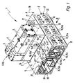
- in perspektivischer Darstellung eine bevorzugte erste Ausführungsform der erfindungsgemäßen Ventileinrichtung, im mit lediglich einer Sonder-Steuereinheit bestückten Zustand, wobei die übrigen Bestückungsplätze unbestückt gezeigt sind,
Figur 2- die Ventileinrichtung aus
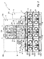
Figur 1 in einer Stirnansicht mit Blickrichtung gemäß Pfeil II, wobei strichpunktiert weitere optional installierbare Steuereinheiten gezeigt sind, - Figur 3
- eine perspektivische Darstellung einer weiteren bevorzugten Ausführungsform der Ventileinrichtung in einer mit
Figur 1 vergleichbaren Darstellungsweise, wobei allerdings ein anderer Typ von Sonder-Steuereinheit vorhanden ist, und Figur 4- eine Stirnansicht der Ventileinrichtung aus
Figur 3 mit Blickrichtung gemäß Pfeil IV.
- FIG. 1
- in a perspective view of a preferred first embodiment of the valve device according to the invention, in the equipped with only a special control unit state, the remaining placement places are shown unpopulated,
- FIG. 2
- the valve device off
FIG. 1 in an end view with viewing direction according to arrow II, where dash-dotted further optional installable control units are shown, - FIG. 3
- a perspective view of another preferred embodiment of the valve device in a with
FIG. 1 comparable presentation, but with a different type of special control unit is present, and - FIG. 4
- an end view of the valve device
FIG. 3 with view in accordance with arrow IV.
Die in Ihrer Gesamtheit mit Bezugsziffer 1 bezeichnete Ventileinrichtung ist als Ventilbatterie konzipiert und enthält einen Ventilträger 2, der gleichzeitig mit einer Mehrzahl von Steuereinheiten 3 bestückbar ist, die jeweils mindestens ein, bevorzugt elektrisch betätigbares, Steuerventil 4 beinhalten.The designated in its entirety by reference numeral 1 valve device is designed as a valve manifold and includes a
Die Steuerventile 4 beinhalten einen mit einem nicht weiter dargestellten beweglichen Ventilglied ausgestatteten Hauptventilteil 5 und mindestens einen diesem zugeordneten Antriebsteil 6. Der Antriebsteil 6 kann elektrisch aktiviert werden und ruft den jeweils gewünschten Schaltzustand des Hauptventilteils 5 hervor. Bei dem Antriebsteil 6 handelt es sich in Verbindung mit einem direkt gesteuerten Steuerventil 4 insbesondere um einen Elektromagnet und im Falle eines vorgesteuerten Steuerventils 4 um ein elektrisch betätigbares Vorsteuerventil, insbesondere ein Magnetventil. Der Antriebsteil 6 kann mehrere Elektromagnete und/oder Vorsteuerventile beinhalten.The
In
Die Außenfläche des Ventilträgers 2 bildet eine bevorzugt ebene Bestückungsfläche 7, an die die Steuereinheiten 3, bevorzugt lösbar, anbaubar sind. Die Bestückungsfläche 7 ist hierbei in mehrere in einer durch einen Doppelpfeil angedeuteten Reihenrichtung 8 aufeinanderfolgende Bestückungsplätze 12 eingeteilt, die zur Bestückung mit den Steuereinheiten 3 nutzbar sind. Die Reihenrichtung 8 fällt insbesondere mit der Längsachse des Ventilträgers 2 zusammen.The outer surface of the
Die Steuereinheiten 3 haben zweckmäßigerweise eine längliche Gestalt. Ihre Längsachse 13 verläuft rechtwinkelig zu der Reihenrichtung 8. Gleiches gilt auch für die jeweils länglichen Bestückungsplätze 12.The control units 3 expediently have an elongated shape. Its
Der Ventilträger 2 ist von einer in ihrer Gesamtheit mit Bezugsziffer 14 bezeichneten, sich aus einer Mehrzahl von Ventilträgerkanälen 15 zusammensetzenden Ventilträger-Kanalanordnung 14 durchsetzt. Unter den Ventilträgerkanälen 15 befindet sich zweckmäßigerweise mindestens ein mit einer externen Druckquelle P verbindbarer Speisekanal 15a und mindestens ein mit einer Drucksenke R, S - insbesondere die Atmosphäre - verbindbarer Abführkanal 15b, 15c. Exemplarisch sind zwei zueinander parallele Abführkanäle 15b, 15c vorhanden, um vor allem bei Steuerventilen 4 mit Vierwege- oder Fünfwegefunktionalität eine optimale Fluidabfuhr zu ermöglichen. Der Speisekanal 15a und die Abführkanäle 15b, 15c erstrecken sich im Innern des Ventilträgers 2 in der Reihenrichtung 8, wobei jeder von ihnen zu jedem Bestückungsplatz 12 ausmündet. Die entsprechenden Kanalmündungen sind durch Bezugsziffern 15a', 15b', 15c' gekennzeichnet.The
Unter den Ventilträgerkanälen 15 befinden sich außerdem Arbeitskanäle 15d, 15e. Während die Speisekanäle 15a, 15b, 15c sämtlichen Bestückungsplätzen 12 gemeinsam zugeordnet sind, man also von einem gemeinsamen Speisekanal 15a und von gemeinsamen Abführkanälen 15b, 15c sprechen kann, sind die Arbeitskanäle 15d, 15e als individuelle Kanäle ausgebildet, wobei zu jedem Bestückungsplatz 12 ein individueller erster Arbeitskanal 15d und insbesondere auch ein individueller zweiter Arbeitskanal 15e ausmündet. Die zugehörigen Kanalmündungen sind durch Bezugsziffern 15d', 15e' kenntlich gemacht. Diese individuellen Arbeitskanäle 15d, 15e sind innerhalb des Ventilträgers 2 nicht miteinander verbunden.Under the
An ihren den Bestückungsplätzen 12 entgegengesetzten Enden münden die Arbeitskanäle 15d, 15e über je eine das Anschließen eines Verbrauchers ermöglichende Verbraucher-Anschlussöffnung 16 zu einer bezüglich der Bestückungsfläche 7 gesonderten Außenfläche des Ventilträgers 2 aus, die im Folgenden als Verbraucher-Anschlussfläche 17 bezeichnet sei. Den Verbraucher-Anschlussöffnungen 16 sind nicht weiter gezeigte Anschlussmittel zugeordnet, an denen jeweils eine zu dem Verbraucher führende Fluidleitung, insbesondere lösbar, angeschlossen werden kann. Bei den Anschlussmitteln handelt es sich beispielsweise um Gewinde oder Steckverbinder.At their positions opposite the
Bevorzugt ist die Verbraucher-Anschlussfläche 17 rechtwinkelig zu der Bestückungsfläche 7 orientiert. Die Verbraucher-Anschlussöffnungen 16 der zum jeweils gleichen Bestückungsplatz 12 führenden Arbeitskanäle 15d, 15e sind vorzugsweise in der durch einen Doppelpfeil angedeuteten Höhenrichtung 18 der Ventileinrichtung 1 übereinander angeordnet, wobei die Höhenrichtung 18 rechtwinkelig zu der Bestückungsfläche 7 orientiert ist.Preferably, the
Die Kanalmündungen 15a' - 15e' bilden an sämtlichen Bestückungsplätzen 12 übereinstimmende Mündungsmuster. Die Mündungsmuster können insbesondere den Normen ISO 5599-2 oder ISO 15407 entsprechen.The
Anstelle zweier individueller Arbeitskanäle 15d, 15e kann den einzelnen Bestückungsplätzen 12 bei Bedarf auch nur ein individueller Arbeitskanal zugeordnet sein.Instead of two
Zur Vereinfachung sind die diversen Kanäle in
Während der Ventilträger 2 prinzipiell einteilig ausgeführt sein kann, setzt er sich bei den Ausführungsbeispielen jeweils aus mehreren in der Reihenrichtung 8 unter Abdichtung aneinandergesetzten Ventilträgersegmenten 22 zusammen. Sie können, entsprechend der gewünschten Baulänge des Ventilträgers 2, in variabler Anzahl miteinander kombiniert werden.While the
Bei den Ausführungsbeispielen definiert jedes Ventilträgersegment 22 zwei in der Reihenrichtung 8 direkt nebeneinander angeordnete Bestückungsplätze 12. Sie gehen insbesondere ansatzlos ineinander über.In the exemplary embodiments, each
Der Übersichtlichkeit wegen sind in der Zeichnung die Übergangsbereiche zwischen benachbarten Bestückungsplätzen 12 durch strichpunktierte Linien 23 kenntlich gemacht.For the sake of clarity, the transitional areas between adjacent placement places 12 are indicated by
Jeder Bestückungsplatz 12 eignet sich grundsätzlich zur Einzelbestückung mittels einer ausschließlich ihm spezifisch zugeordneten Steuereinheit 3, die der besseren Unterscheidung wegen im Folgenden als Standard-Steuereinheit 3a bezeichnet sei. Die in der Reihenrichtung 8 gemessene Breite jeder Standard-Steuereinheit 3a übersteigt nicht die entsprechend gemessene Breite des zugeordneten Bestückungsplatzes 12, wobei insbesondere im Wesentlichen die gleiche Breite vorliegt. Bei dem gezeigten Ausführungsbeispiel können somit auf jedem Ventilträgersegment 22 prinzipiell zwei Standard-Steuereinheiten 3a gleichzeitig platziert werden.Each
Die Standard-Steuereinheiten 3a verfügen über nicht weiter dargestellte interne Kanäle, die zur der dem Bestückungsplatz 12 zugewandten Grundfläche so ausmünden, dass im montierten Zustand eine zuordnungsrichtige Verbindung zu den am betreffenden Bestückungsplatz 12 ausmündenden Ventilträgerkanälen 15 stattfindet.The standard control units 3 a have internal channels (not shown further) which open out to the base area facing the
Die Standard-Steuereinheit 3a kann im einfachsten Fall aus allein einem Steuerventil 4 bestehen. In
Mindestens eine Steuereinheit 3 der Ventileinrichtung 1 - im Folgenden als Sonder-Steuereinheit 3b bezeichnet - weicht breitenmäßig vom Rastermaß der Bestückungsplätze 12 und mithin auch demjenigen der Standard-Steuereinheiten 3a ab, indem seine Breite insbesondere einem ganzzahligen Vielfachen der in der Reihenrichtung 8 gemessenen Breite eines Bestückungsplatzes 12 entspricht. Besonders vorteilhaft wird hierbei die bei den Ausführungsbeispielen realisierte doppelte Breite eines Bestückungsplatzes 12 angesehen.At least one control unit 3 of the valve device 1-referred to below as a special control unit 3b-deviates in width from the pitch of the
Anhand einerseits
An dieser Stelle sei erwähnt, dass ohne Weiteres gleichzeitig unterschiedliche Typen von Sonder-Steuereinheiten 3b an ein und derselben Bestückungsfläche 7 der Ventileinrichtung 1 montiert sein können. Es ist ferner möglich, die gesamte Bestückungsfläche 7 ausschließlich mit Sonder-Steuereinheiten 3b zu bestücken oder aber mit einer Mischung aus einer beliebigen Anzahl von Sonder-Steuereinheiten 3b und Standard-Steuereinheiten 3a. Dies ermöglicht eine variable Ausstattung der Ventileinrichtung 1 unter Berücksichtigung der jeweiligen Einsatzbedingungen.At this point it should be mentioned that different types of special control units 3b can be mounted on one and the same mounting
Die Sonder-Steuereinheit 3b enthält eine mindestens ein Steuerventil 4 tragende Zwischenplatte 24. Soweit im Folgenden allgemein von einer Zwischenplatte die Rede ist, ist diejenige einer Sonder-Steuereinheit 3b gemeint. Sofern eine Bezugnahme auf die Zwischenplatte 23 einer Standard-Steuereinheit 3a beabsichtigt ist, wird dies explizit erwähnt.The special control unit 3b contains an
Die Zwischenplatte 24 ist mit ihrer Unterseite 25 voraus an die Bestückungsfläche 7 angesetzt, wobei sie aufgrund ihrer entsprechend großen Breite zwei unmittelbar nebeneinanderliegende Bestückungsplätze 12 der Bestückungsfläche 7 überdeckt. Ihre in der Reihenrichtung 8 gemessene Breite entspricht der doppelten Breite eines Bestückungsplatzes 12, wobei anzumerken ist, dass beim Ausführungsbeispiel sämtliche Bestückungsplätze 12 über die gleichen Abmessungen verfügen. Vorzugsweise besitzt jeder Bestückungsplatz überdies einen rechteckigen Umriss.The
Die Zwischenplatte 24 kann bei entsprechend größerer Breite auch mehr als zwei Bestückungsplätze 12 abdecken.The
Mindestens ein Steuerventil 4 könnte prinzipiell stirnseitig an der bevorzugt quaderförmigen Zwischenplatte 24 angebracht sein. Vorgezogen wird allerdings die gezeigte Bauform mit an der dem Ventilträger 2 entgegengesetzten Oberseite 26 der Zwischenplatte 24 installiertem mindestens einem Steuerventil 4. Man kann hierbei von einer Höhenverkettung sprechen.At least one
Bei dem Ausführungsbeispiel der
Bei dem Ausführungsbeispiel der
Die Zwischenplatte 24 jeder Sonder-Steuereinheit 3b ist von einer allgemein mit Bezugsziffer 28 bezeichneten Zwischenplatten-Kanalanordnung durchsetzt, die sich aus einer Vielzahl von in geeigneter Weise verlaufenden Zwischenplattenkanälen 32 zusammensetzt. Mit einigen der Zwischenplattenkanäle 32 mündet die Zwischenplatten-Kanalanordnung 28 derart verteilt an der Unterseite 25 der Zwischenplatte 24 aus, dass verschiedene Kanalverbindungen mit den an den überdeckten Bestückungsplätzen 12 ausmündenden Ventilträgerkanälen 12 entstehen.The
Auf diese Weise kann im Bereich jedes von der Zwischenplatte 24 überdeckten Bestückungsplatzes 12 eine Fluidverbindung zwischen Ventilträgerkanälen 15 und Zwischenplattenkanälen 32 stattfinden. Die Kanalverknüpfung ist also nicht auf die Breite eines einzigen Bestückungsplatzes 12 begrenzt, sondern kann sich über eine größere Breite erstrecken.In this way, a fluid connection between
Zumindest einige der Zwischenplattenkanäle 32 münden (auch) zu dem mindestens einen Ventilmontageplatz 27 aus und stehen mit Ventilkanälen 33 des dort jeweils montierten Steuerventils 4 in Fluidverbindung. Die Ventilkanäle 33 münden so an der der Zwischenplatte 24 zugewandten Unterseite des betreffenden Steuerventils 4 aus, dass ein fluchtender Übergang zu den am Ventilmontageplatz 27 vorhandenen Kanalmündungen der Zwischenplattenkanäle 32 erfolgt.At least some of the intermediate plate channels 32 open (also) to the at least one
Entsprechend der gewählten Ausgestaltung der Zwischenplatten-Kanalanordnung 28 und der Anzahl der vorhandenen Steuerventile 4 kann innerhalb einer Sonder-Steuereinheit 3b eine für einen speziellen Anwendungsfall konzipierte fluidische Schaltung realisiert werden. Da in diese Schaltung zu mehreren Bestückungsplätzen 12 ausmündende Ventilträgerkanäle 15 einbezogen werden können, lassen sich auf engstem Raum auch sehr komplexe und anspruchsvolle Schaltungen realisieren, ganz ohne zusätzliche externe Leitungsverbindungen.According to the selected configuration of the intermediate
Beispielsweise zeichnet sich die Sonder-Steuereinheit 3b des Ausführungsbeispiels der
Ein erster (32a) dieser beiden Verbindungskanäle kommuniziert insbesondere mit zwei zu unterschiedlichen Bestückungsplätzen 12 ausmündenden ersten Arbeitskanälen 15d und ist im Übrigen über einen weiteren Zwischenplattenkanal 32c derart an das einzige Steuerventil 4 angeschlossen, dass er durch dieses, bei entsprechender Schaltstellung, mit Druckmedium aus dem gemeinsamen Speisekanal 15a versorgt werden kann. Auf diese Weise besteht die Möglichkeit, einen gleichzeitig an die Verbraucher-Anschlussöffnungen 16 beider erster Arbeitskanäle 15d angeschlossenen Verbraucher mit höherem Durchfluss zu versorgen oder aber unterschiedliche Verbraucher verzögerungsfrei gleichzeitig mit Druckmedium zu beaufschlagen.A first one (32a) of these two connection channels communicates in particular with two
Speziell wenn ein relativ hoher Fluiddurchsatz gewünscht ist, kann ein zweiter Verbindungskanal 32b so an der Unterseite 25 ausmünden, dass er an unterschiedlichen Bestückungsplätzen 12 beide Male mit dem Speisekanal 15a kommuniziert. Ein weiterer Zwischenplattenkanal 32d schließt den zweiten Verbindungskanal 32b an das Steuerventil 4 an.Especially if a relatively high fluid throughput is desired, a second connection channel 32b can open out at the
In der nicht dargestellten Offenstellung des Steuerventils 4 wird Druckmedium aus dem Speisekanal 15a über den zweiten Verbindungskanal 32b und den darauf folgenden weiteren Zwischenplattenkanal 32d in den weiteren Zwischenplattenkanal 32c eingespeist, von wo aus es über den ersten Verbindungskanal 32a in die beiden ersten Arbeitskanäle 15d überströmt.In the open position of the
Ein als Rückführkanal 32e ausgebildeter Zwischenplattenkanal 32 verläuft zwischen dem Ventilmontageplatz 27 und der Unterseite 25 und verbindet das Steuerventil 4 mit einem Abführkanal 15b. Auf diese Weise kann die Fluidrückführung vom jeweils angeschlossenen Verbraucher stattfinden, wenn das Steuerventil 4 die abgebildete Schließstellung einnimmt.An intermediate plate channel 32 designed as a return channel 32e extends between the
Je nach Anwendung, könnte auf den ersten oder zweiten Verbindungskanal 32a, 32b auch verzichtet werden.Depending on the application, the first or second connection channel 32a, 32b could also be dispensed with.
Ist die Zwischenplatte 24 mit mindestens einer Vakuumerzeugereinrichtung 34 ausgestattet, die über das Steuerventil 4 mit Druckluft gespeist wird, kann an den entsprechend angeschlossenen ersten und/oder zweiten Arbeitskanälen 15b, 15e ein Unterdruck abgegriffen werden. Durch einen modifizierten Verlauf des ersten Verbindungskanals 32a können gleichzeitig zwei Arbeitskanäle 15d an ein und dieselbe Vakuumerzeugereinrichtung 34 angeschlossen sein.If the
Die Vakuumerzeugereinrichtung 34 arbeitet insbesondere nach dem Ejektorprinzip und enthält eine Saugdüse, die einen Unterdruck hervorruft, wenn sie von Druckluft durchströmt wird.The
Jedenfalls kann auf diese Weise mittels nur eines einzigen Steuerventils 4 der Sonder-Steuereinheit 3b die Unterdruckversorgung von Arbeitskanälen gesteuert werden, die von unterschiedlichen Bestückungsplätzen 12 ausgehen.In any case, can be controlled in this way by means of only a
Eine besonders gute Performance lässt sich erzielen, wenn gleichzeitig zwei Vakuumerzeugereinrichtungen 34 über ein einziges Steuerventil 4 betrieben werden, wobei gleichzeitig über zwei Bestückungsplätze 12 hinweg eine Vakuumabgabe möglich ist.A particularly good performance can be achieved if two
Bei dem Ausführungsbeispiel der
Auf diese Weise lässt sich eine insbesondere bei Pressen genutzte Sicherheitsschaltung realisieren, die dem einen Arbeitskanal 15d nur dann Druckmedium zuführt, wenn beide Steuerventile 4 aktiviert sind. Somit können unkontrollierte Arbeitshübe einer Presse oder einer sonstigen Maschine verhindert werden.In this way, it is possible to realize a safety circuit, which is used in particular for presses, and which only supplies pressure medium to one working
Zwar lassen sich gerade die beschriebenen Schaltungen in Verbindung mit den Sonder-Steuereinheiten 3b besonders vorteilhaft verwenden. Gleichwohl ist die Erläuterung dieser Schaltungen exemplarisch zu verstehen und es können ohne weiteres auch andere Arten von Schaltungen realisiert werden.Although the circuits described in connection with the special control units 3b can be used particularly advantageously. However, the explanation of these circuits is to be understood by way of example and other types of circuits can be readily realized.
Da die Steuerventile 4 bevorzugt vom elektrisch betätigbaren Typ sind, empfiehlt sich die Übermittlung der für sie vorgesehenen elektrischen Steuersignale mittels einer im Innern des Ventilträgers 2 verlaufenden elektrischen Signalübertragungseinrichtung 35. Selbige ist in der Zeichnung nur schematisch angedeutet und erstreckt sich insbesondere in einem den Ventilträger 2 in der Reihenrichtung 8 durchsetzenden Signalübermittlungskanal 36. An jedem Bestückungsplatz 12 ist eine mit der Signalübertragungseinrichtung 35 verbundene elektrische Schnittstelle vorgesehen, die über die angebaute Zwischenplatte 23, 34 durchsetzende elektrische Leiter mit dem von der Zwischenplatte 23, 24 getragenen Antriebsteil 6 des mindestens einen Steuerventils 4 verbunden ist. Bei einer Standard-Steuereinheit 3a ohne Zwischenplatte 23 können die Antriebsteile 6 direkt mit der elektrischen Schnittstelle verbunden werden. Bei 37 sind im Bereich der Bestückungsplätze 12 vorgesehene Durchbrechungen des Ventilträgers 2 ersichtlich, durch die hindurch die elektrische Verbindung zwischen der Signalübertragungseinrichtung 35 und der jeweils zugeordneten Steuereinheit 3 stattfinden kann.Since the
Die elektrischen Steuersignale könnten abweichend vom Ausführungsbeispiel auch ohne Verwendung des Ventilträgers 2 zugeführt werden, z.B. über einzelne Kabel.Deviating from the embodiment, the electrical control signals could also be supplied without using the
Die beispielhafte Ventileinrichtung ermöglicht einen modularen Ausbau. Die elektrischen Anschlüsse wie auch die fluidischen Anschlüsse können über den Ventilträger 2 vorgenommen werden. Innerhalb einer Sonder-Steuereinheit 3b werden quasi wenigstens zwei ansonsten zur Einzelbestückung mit Standard-Steuereinheiten 3a nutzbare Bestückungsplätze 12 nach Art einer Höhenverkettung zusammengefasst, ohne dass auf externe Schlauchverbindungen zurückgegriffen werden müsste. Abgesehen von der Sonder-Steuereinheit 3b kann die Ventileinrichtung konventionell ausgestattet sein, es bedarf insbesondere keiner Modifikationen an den eventuell verwendeten Standard-Steuereinheiten 3a.The exemplary valve device allows a modular expansion. The electrical connections as well as the fluidic connections can be made via the
Ohne weiteres kann man wenigstens zwei Verbraucher-Anschlussöffnungen 16 zusammenschalten, um einen erhöhten Durchfluss zu erzielen. Zu erwähnen ist schließlich auch noch, dass insbesondere bei einer Ausstattung mit nur einem Steuerventil 4 neben diesem Steuerventil 4 platzsparend eine Sensoreinrichtung untergebracht werden kann, die den Betrieb des Steuerventils 4 überwacht und/oder die - wenn sie mit einem Drucksensor oder Druckschalter ausgestattet ist - eine Drucküberwachung vornehmen kann.It is readily possible to interconnect at least two
Die Zwischenplatten-Kanalanordnung 28 hat nicht notwendigerweise mit sämtlichen an den von der Zwischenplatte 24 der Sonder-Steuereinheit 3b überdeckten Bestückungsplätzen 12 ausmündenden Ventilträgerkanälen 15 zu kommunizieren. Die Mündungen nicht benötigter Ventilträgerkanäle 15 können durch die Zwischenplatte 24 einfach dicht abgedeckt werden, wie dies in
Claims (17)
- Valve unit comprising a valve support (2) having a mounting surface (7) divided into a plurality of mounting locations (12) arranged consecutively in the direction of a row (8), at each of which terminate several valve support passages (15) of a valve support passage arrangement (14) passing through the valve support (2) and which can individually be fitted with control units (3) comprising at least one control valve (4), characterised in that the mounting surface (7) is equipped with at least one special control unit (3b) having an interconnecting plate (24) fitted to the mounting surface (7) with its bottom side (25) and covering several immediately adjacent mounting locations (12) owing to its width, through which interconnecting plate passes an interconnecting plate passage arrangement (28) connected to the valve support passage arrangement (14) at the covered mounting locations (12) and which interconnecting plate supports at least one control valve (4) connected to the interconnecting plate passage arrangement (28).
- Valve unit according to claim 1, characterised in that the interconnecting plate passage arrangement (28) includes at least one connecting passage (32a', 32b') connecting at least two control valves (4) of the special control unit (3b) to one another.
- Valve unit according to claim 1 or 2, characterised in that the interconnecting plate passage arrangement (28) includes at least one connecting passage (32a, 32b) connecting at least two valve support passages (15) terminating at different mounting locations (12) to one another.
- Valve unit according to any of claims 1 to 3, characterised in that an operating passage (15d, 15e) of the valve support passage arrangement (14) which can be connected to a load terminates at each of the mounting locations (12) covered by the interconnecting plate (34).
- Valve unit according to any of claims 1 to 4, characterised in that at least one individual operating passage (15d, 15e) of the valve support passage arrangement (14) terminates at each mounting location (12), the other end terminating at an outer surface of the valve support (2) which is located remote from the mounting surface (7) via a load port (16) allowing the connection of a load.
- Valve unit according to claim 4 or 5, characterised in that a connecting passage (32a) of the interconnecting plate (24) connects at least two operating passages (12d) terminating at different covered mounting locations (12) to one another.
- Valve unit according to any of claims 1 to 6, characterised in that a valve support passage (15) is designed as a common feed passage (15a) terminating at each mounting location (12) for the common fluid supply of all mounting locations (12).
- Valve unit according to claim 7, characterised in that a connecting passage (32b) of the interconnecting plate (24) is connected to the common feed passage (15a) in at least two different covered mounting locations (12).
- Valve unit according to any of claims 1 to 8, characterised in that the interconnecting plate (24) is fitted with only one or with two control valves (4).
- Valve unit according to claim 9, characterised in that at least one connecting passage (32a', 32b') of the interconnecting plate passage arrangement (28) connects two control valves (4) to one another.
- Valve unit according to any of claims 1 to 10, characterised in that the at least one control valve (4) is located on the top (26) of the interconnecting plate (24) opposite the valve support (2).
- Valve unit according to any of claims 1 to 11, characterised in that the interconnecting plate (24) covers exactly two adjacent mounting locations (12).
- Valve unit according to any of claims 1 to 12, characterised in that several special control units (3b) are arranged on the mounting surface (7).
- Valve unit according to any of claims 1 to 13, characterised in that at least one special control unit (3b) and at least one control unit (3a) covering only one mounting surface (12) are disposed on the mounting surface (7) at the same time.
- Valve unit according to any of claims 1 to 14, characterised in that the interconnecting plate (24) is fitted with at least one vacuum generating device (34) controllable by a control valve (4) supported by the interconnecting plate (24).
- Valve unit according to any of claims 1 to 15, characterised in that the at least one control valve (4) is of a type which is operated electrically.
- Valve unit according to any of claims 1 to 16, characterised in that the valve support (2) is made up from a plurality of valve support segments (22) fitted to one another in the direction of the row (8), each defining at least one of the mounting locations (12).
Applications Claiming Priority (2)
| Application Number | Priority Date | Filing Date | Title |
|---|---|---|---|
| DE102006056089A DE102006056089A1 (en) | 2006-11-28 | 2006-11-28 | valve means |
| PCT/EP2007/009421 WO2008064755A1 (en) | 2006-11-28 | 2007-10-30 | Valve apparatus |
Publications (2)
| Publication Number | Publication Date |
|---|---|
| EP2047112A1 EP2047112A1 (en) | 2009-04-15 |
| EP2047112B1 true EP2047112B1 (en) | 2010-05-12 |
Family
ID=38988322
Family Applications (1)
| Application Number | Title | Priority Date | Filing Date |
|---|---|---|---|
| EP20070846520 Active EP2047112B1 (en) | 2006-11-28 | 2007-10-30 | Valve apparatus |
Country Status (6)
| Country | Link |
|---|---|
| US (1) | US8082943B2 (en) |
| EP (1) | EP2047112B1 (en) |
| CN (1) | CN101542135B (en) |
| AT (1) | ATE467770T1 (en) |
| DE (2) | DE102006056089A1 (en) |
| WO (1) | WO2008064755A1 (en) |
Families Citing this family (19)
| Publication number | Priority date | Publication date | Assignee | Title |
|---|---|---|---|---|
| FR2901851B1 (en) * | 2006-06-02 | 2010-11-19 | Parker Hannifin France Holding | ILOT FOR PNEUMATIC DISTIBUTEERS |
| US8413679B2 (en) * | 2008-04-15 | 2013-04-09 | Festo Ag & Co. Kg | Modular control device, especially of an electro-fluidic type |
| KR101599344B1 (en) * | 2011-09-30 | 2016-03-03 | 가부시키가이샤 후지킨 | Gas supply device |
| US10180191B2 (en) * | 2014-06-20 | 2019-01-15 | Asco, L.P. | Zoned manifold assembly for solenoid valve control system |
| DE202015000540U1 (en) * | 2015-01-27 | 2015-04-10 | Kendrion Kuhnke Automotive GmbH | Pneumatic control and measuring device and seating comfort system |
| DE202016100111U1 (en) * | 2016-01-13 | 2017-04-20 | J. Schmalz Gmbh | Plant for handling workpieces |
| US10092931B2 (en) * | 2016-04-19 | 2018-10-09 | Lamb Weston, Inc. | Food article defect removal apparatus |
| US10052663B2 (en) * | 2016-04-19 | 2018-08-21 | Lamb Weston, Inc. | Food article defect removal apparatus |
| US11493275B2 (en) | 2017-10-10 | 2022-11-08 | Tps Ip, Llc | Oven with renewable energy capacities |
| US11299925B2 (en) | 2017-10-11 | 2022-04-12 | Tps Ip, Llc | Oven with split doors |
| US11585701B2 (en) | 2017-10-27 | 2023-02-21 | Tps Ip, Llc | Intelligent oven |
| US10794508B2 (en) * | 2017-11-14 | 2020-10-06 | Tps Ip, Llc | Atmosphere control manifold |
| US10798947B2 (en) | 2017-12-08 | 2020-10-13 | Tps Ip, Llc | Oven with augmented reality functionality |
| US10731677B2 (en) * | 2017-12-27 | 2020-08-04 | Mac Valves, Inc. | Pneumatic control valve manifold |
| US11346560B2 (en) | 2017-12-29 | 2022-05-31 | Tps Ip, Llc | Oven wall compositions and/or structures |
| DE102018215218A1 (en) * | 2018-09-07 | 2020-03-12 | Festo Ag & Co. Kg | Fluid module arrangement |
| JP6975749B2 (en) * | 2019-05-15 | 2021-12-01 | Ckd株式会社 | Pilot solenoid valve |
| DE102019208495A1 (en) * | 2019-06-12 | 2020-12-17 | Sms Group Gmbh | Hydraulic control device in rolling mill construction |
| CN111745673A (en) * | 2020-07-09 | 2020-10-09 | 伯朗特机器人股份有限公司 | Universal pneumatic control mechanism for industrial robot clamp |
Family Cites Families (15)
| Publication number | Priority date | Publication date | Assignee | Title |
|---|---|---|---|---|
| US3213883A (en) * | 1962-09-13 | 1965-10-26 | Carls William | Two-piece multiple valve manifold |
| JPS5325775A (en) * | 1976-08-24 | 1978-03-09 | Miller Fluid Power Corp | Module type fluid flow control element |
| DE4226539A1 (en) * | 1992-08-11 | 1994-02-17 | Bosch Gmbh Robert | Electropneumatic valve assembly |
| DE4444024A1 (en) * | 1994-12-10 | 1996-06-13 | Festo Kg | Control device, in particular for controlling valves |
| US6053198A (en) * | 1997-12-01 | 2000-04-25 | Numatics, Incorporated | Solenoid valve control system |
| DE29810091U1 (en) * | 1998-06-05 | 1998-12-10 | Airtec Pneumatic Gmbh | Valve terminal with a series of switching valves |
| FR2807793B1 (en) * | 2000-04-17 | 2002-05-31 | Parker Hannifin Rak Sa | INTERFACE MODULE FOR ELECTROPNEUMATIC VALVE ISLAND |
| JP3825288B2 (en) * | 2001-08-13 | 2006-09-27 | Smc株式会社 | Manifold for solenoid valve |
| FR2829194B1 (en) * | 2001-09-05 | 2004-11-19 | Parker Hannifin Rak Sa | PNEUMATIC MODULE ISLAND |
| DE10213397B4 (en) * | 2002-03-26 | 2005-04-14 | Festo Ag & Co. | valve assembly |
| GB0217709D0 (en) | 2002-07-31 | 2002-09-11 | Koninkl Philips Electronics Nv | Array device with switching circuits |
| DE10347936B4 (en) * | 2003-10-15 | 2007-09-27 | Bosch Rexroth Pneumatics Gmbh | Valve assembly with adjustable function and method therefor |
| DE102004046547A1 (en) * | 2004-09-20 | 2006-04-06 | Festo Ag & Co. | Fluid technical device with pressure regulator |
| JP4919002B2 (en) * | 2005-06-20 | 2012-04-18 | Smc株式会社 | Manifold solenoid valve assembly |
| DE202006008921U1 (en) * | 2006-06-07 | 2006-08-10 | Festo Ag & Co. | Valve arrangement with a connector plate comprises at least one electrically operatable multiway valve with specified fluid connection on its bottom and top surfaces |
-
2006
- 2006-11-28 DE DE102006056089A patent/DE102006056089A1/en not_active Withdrawn
-
2007
- 2007-10-30 AT AT07846520T patent/ATE467770T1/en active
- 2007-10-30 EP EP20070846520 patent/EP2047112B1/en active Active
- 2007-10-30 WO PCT/EP2007/009421 patent/WO2008064755A1/en active Application Filing
- 2007-10-30 US US12/310,866 patent/US8082943B2/en not_active Expired - Fee Related
- 2007-10-30 CN CN2007800443629A patent/CN101542135B/en not_active Expired - Fee Related
- 2007-10-30 DE DE200750003771 patent/DE502007003771D1/en active Active
Also Published As
| Publication number | Publication date |
|---|---|
| CN101542135A (en) | 2009-09-23 |
| WO2008064755A1 (en) | 2008-06-05 |
| ATE467770T1 (en) | 2010-05-15 |
| DE102006056089A1 (en) | 2008-05-29 |
| EP2047112A1 (en) | 2009-04-15 |
| DE502007003771D1 (en) | 2010-06-24 |
| US8082943B2 (en) | 2011-12-27 |
| CN101542135B (en) | 2012-02-08 |
| US20090205724A1 (en) | 2009-08-20 |
Similar Documents
| Publication | Publication Date | Title |
|---|---|---|
| EP2047112B1 (en) | Valve apparatus | |
| DE60301746T2 (en) | Pneumatic valve group with easy installation and easy maintenance | |
| EP2024648B1 (en) | Valve arrangement | |
| EP1013940B1 (en) | Valve arrangement | |
| WO1994004831A1 (en) | Electro-pneumatic control device | |
| DE19711227C2 (en) | Valve arrangement | |
| WO2008138371A1 (en) | Modular valve arrangement for different throughflow categories | |
| EP1041325B1 (en) | Valve assembly | |
| DE102007041583B4 (en) | valve means | |
| EP3296602B1 (en) | Fluid distribution apparatus | |
| DE102007040929B3 (en) | Valve unit has working channel with magnetic valve on edge of mounting zone for second magnetic valve controlling flow through second working channel, first valve having mounting surface for second valve or pressure monitor | |
| EP2514977B1 (en) | Control bloc for a press | |
| DE10213397B4 (en) | valve assembly | |
| EP2530334B1 (en) | Valve assembly | |
| DE4312729A1 (en) | Valve station | |
| DE10153545B4 (en) | Fluid force locking system and method for locking fluid force signals | |
| EP1991791B1 (en) | Valve bank comprising a safety valve | |
| EP2674652B1 (en) | Valve assembly with pinch valves | |
| EP2110563B1 (en) | Valve assembly with central fluid cut-off device | |
| EP1251283B1 (en) | Kit for making a fluid control device | |
| EP2770216B1 (en) | Valve assembly | |
| DE102005005612A1 (en) | Valve arrangement comprises multiple valve units together with main valve and pilot valve that feeds the valve arrangement with control fluid | |
| WO2011038813A1 (en) | High-pressure distribution block in a coolant-lubricant supply device | |
| DE19909920A1 (en) | Safety switching device for pneumatic motor, with compressed air supply line connected to second connection of first switching valve | |
| EP1182358B1 (en) | Configuration unit |
Legal Events
| Date | Code | Title | Description |
|---|---|---|---|
| PUAI | Public reference made under article 153(3) epc to a published international application that has entered the european phase |
Free format text: ORIGINAL CODE: 0009012 |
|
| 17P | Request for examination filed |
Effective date: 20081202 |
|
| AK | Designated contracting states |
Kind code of ref document: A1 Designated state(s): AT BE BG CH CY CZ DE DK EE ES FI FR GB GR HU IE IS IT LI LT LU LV MC MT NL PL PT RO SE SI SK TR |
|
| AX | Request for extension of the european patent |
Extension state: AL BA HR MK RS |
|
| GRAP | Despatch of communication of intention to grant a patent |
Free format text: ORIGINAL CODE: EPIDOSNIGR1 |
|
| GRAC | Information related to communication of intention to grant a patent modified |
Free format text: ORIGINAL CODE: EPIDOSCIGR1 |
|
| DAX | Request for extension of the european patent (deleted) | ||
| GRAS | Grant fee paid |
Free format text: ORIGINAL CODE: EPIDOSNIGR3 |
|
| GRAA | (expected) grant |
Free format text: ORIGINAL CODE: 0009210 |
|
| AK | Designated contracting states |
Kind code of ref document: B1 Designated state(s): AT BE BG CH CY CZ DE DK EE ES FI FR GB GR HU IE IS IT LI LT LU LV MC MT NL PL PT RO SE SI SK TR |
|
| REG | Reference to a national code |
Ref country code: GB Ref legal event code: FG4D Free format text: NOT ENGLISH |
|
| REG | Reference to a national code |
Ref country code: CH Ref legal event code: EP |
|
| REG | Reference to a national code |
Ref country code: IE Ref legal event code: FG4D Free format text: LANGUAGE OF EP DOCUMENT: GERMAN |
|
| REF | Corresponds to: |
Ref document number: 502007003771 Country of ref document: DE Date of ref document: 20100624 Kind code of ref document: P |
|
| REG | Reference to a national code |
Ref country code: NL Ref legal event code: VDEP Effective date: 20100512 |
|
| LTIE | Lt: invalidation of european patent or patent extension |
Effective date: 20100512 |
|
| PG25 | Lapsed in a contracting state [announced via postgrant information from national office to epo] |
Ref country code: ES Free format text: LAPSE BECAUSE OF FAILURE TO SUBMIT A TRANSLATION OF THE DESCRIPTION OR TO PAY THE FEE WITHIN THE PRESCRIBED TIME-LIMIT Effective date: 20100823 Ref country code: LT Free format text: LAPSE BECAUSE OF FAILURE TO SUBMIT A TRANSLATION OF THE DESCRIPTION OR TO PAY THE FEE WITHIN THE PRESCRIBED TIME-LIMIT Effective date: 20100512 Ref country code: NL Free format text: LAPSE BECAUSE OF FAILURE TO SUBMIT A TRANSLATION OF THE DESCRIPTION OR TO PAY THE FEE WITHIN THE PRESCRIBED TIME-LIMIT Effective date: 20100512 Ref country code: SE Free format text: LAPSE BECAUSE OF FAILURE TO SUBMIT A TRANSLATION OF THE DESCRIPTION OR TO PAY THE FEE WITHIN THE PRESCRIBED TIME-LIMIT Effective date: 20100512 |
|
| PG25 | Lapsed in a contracting state [announced via postgrant information from national office to epo] |
Ref country code: SI Free format text: LAPSE BECAUSE OF FAILURE TO SUBMIT A TRANSLATION OF THE DESCRIPTION OR TO PAY THE FEE WITHIN THE PRESCRIBED TIME-LIMIT Effective date: 20100512 Ref country code: LV Free format text: LAPSE BECAUSE OF FAILURE TO SUBMIT A TRANSLATION OF THE DESCRIPTION OR TO PAY THE FEE WITHIN THE PRESCRIBED TIME-LIMIT Effective date: 20100512 Ref country code: IS Free format text: LAPSE BECAUSE OF FAILURE TO SUBMIT A TRANSLATION OF THE DESCRIPTION OR TO PAY THE FEE WITHIN THE PRESCRIBED TIME-LIMIT Effective date: 20100912 Ref country code: FI Free format text: LAPSE BECAUSE OF FAILURE TO SUBMIT A TRANSLATION OF THE DESCRIPTION OR TO PAY THE FEE WITHIN THE PRESCRIBED TIME-LIMIT Effective date: 20100512 |
|
| REG | Reference to a national code |
Ref country code: IE Ref legal event code: FD4D |
|
| PG25 | Lapsed in a contracting state [announced via postgrant information from national office to epo] |
Ref country code: CY Free format text: LAPSE BECAUSE OF FAILURE TO SUBMIT A TRANSLATION OF THE DESCRIPTION OR TO PAY THE FEE WITHIN THE PRESCRIBED TIME-LIMIT Effective date: 20100609 Ref country code: PL Free format text: LAPSE BECAUSE OF FAILURE TO SUBMIT A TRANSLATION OF THE DESCRIPTION OR TO PAY THE FEE WITHIN THE PRESCRIBED TIME-LIMIT Effective date: 20100512 |
|
| PG25 | Lapsed in a contracting state [announced via postgrant information from national office to epo] |
Ref country code: EE Free format text: LAPSE BECAUSE OF FAILURE TO SUBMIT A TRANSLATION OF THE DESCRIPTION OR TO PAY THE FEE WITHIN THE PRESCRIBED TIME-LIMIT Effective date: 20100512 Ref country code: DK Free format text: LAPSE BECAUSE OF FAILURE TO SUBMIT A TRANSLATION OF THE DESCRIPTION OR TO PAY THE FEE WITHIN THE PRESCRIBED TIME-LIMIT Effective date: 20100512 Ref country code: IE Free format text: LAPSE BECAUSE OF FAILURE TO SUBMIT A TRANSLATION OF THE DESCRIPTION OR TO PAY THE FEE WITHIN THE PRESCRIBED TIME-LIMIT Effective date: 20100512 Ref country code: PT Free format text: LAPSE BECAUSE OF FAILURE TO SUBMIT A TRANSLATION OF THE DESCRIPTION OR TO PAY THE FEE WITHIN THE PRESCRIBED TIME-LIMIT Effective date: 20100913 |
|
| PG25 | Lapsed in a contracting state [announced via postgrant information from national office to epo] |
Ref country code: RO Free format text: LAPSE BECAUSE OF FAILURE TO SUBMIT A TRANSLATION OF THE DESCRIPTION OR TO PAY THE FEE WITHIN THE PRESCRIBED TIME-LIMIT Effective date: 20100512 Ref country code: CZ Free format text: LAPSE BECAUSE OF FAILURE TO SUBMIT A TRANSLATION OF THE DESCRIPTION OR TO PAY THE FEE WITHIN THE PRESCRIBED TIME-LIMIT Effective date: 20100512 Ref country code: SK Free format text: LAPSE BECAUSE OF FAILURE TO SUBMIT A TRANSLATION OF THE DESCRIPTION OR TO PAY THE FEE WITHIN THE PRESCRIBED TIME-LIMIT Effective date: 20100512 |
|
| PLBE | No opposition filed within time limit |
Free format text: ORIGINAL CODE: 0009261 |
|
| STAA | Information on the status of an ep patent application or granted ep patent |
Free format text: STATUS: NO OPPOSITION FILED WITHIN TIME LIMIT |
|
| 26N | No opposition filed |
Effective date: 20110215 |
|
| BERE | Be: lapsed |
Owner name: FESTO A.G. & CO. KG Effective date: 20101031 |
|
| PG25 | Lapsed in a contracting state [announced via postgrant information from national office to epo] |
Ref country code: MC Free format text: LAPSE BECAUSE OF NON-PAYMENT OF DUE FEES Effective date: 20101031 Ref country code: GR Free format text: LAPSE BECAUSE OF FAILURE TO SUBMIT A TRANSLATION OF THE DESCRIPTION OR TO PAY THE FEE WITHIN THE PRESCRIBED TIME-LIMIT Effective date: 20100813 |
|
| REG | Reference to a national code |
Ref country code: DE Ref legal event code: R097 Ref document number: 502007003771 Country of ref document: DE Effective date: 20110214 |
|
| PG25 | Lapsed in a contracting state [announced via postgrant information from national office to epo] |
Ref country code: BE Free format text: LAPSE BECAUSE OF NON-PAYMENT OF DUE FEES Effective date: 20101031 |
|
| PG25 | Lapsed in a contracting state [announced via postgrant information from national office to epo] |
Ref country code: IT Free format text: LAPSE BECAUSE OF NON-PAYMENT OF DUE FEES Effective date: 20101030 Ref country code: MT Free format text: LAPSE BECAUSE OF FAILURE TO SUBMIT A TRANSLATION OF THE DESCRIPTION OR TO PAY THE FEE WITHIN THE PRESCRIBED TIME-LIMIT Effective date: 20100512 |
|
| REG | Reference to a national code |
Ref country code: CH Ref legal event code: PL |
|
| PG25 | Lapsed in a contracting state [announced via postgrant information from national office to epo] |
Ref country code: LI Free format text: LAPSE BECAUSE OF NON-PAYMENT OF DUE FEES Effective date: 20111031 Ref country code: CH Free format text: LAPSE BECAUSE OF NON-PAYMENT OF DUE FEES Effective date: 20111031 |
|
| PG25 | Lapsed in a contracting state [announced via postgrant information from national office to epo] |
Ref country code: BG Free format text: LAPSE BECAUSE OF FAILURE TO SUBMIT A TRANSLATION OF THE DESCRIPTION OR TO PAY THE FEE WITHIN THE PRESCRIBED TIME-LIMIT Effective date: 20100512 Ref country code: HU Free format text: LAPSE BECAUSE OF FAILURE TO SUBMIT A TRANSLATION OF THE DESCRIPTION OR TO PAY THE FEE WITHIN THE PRESCRIBED TIME-LIMIT Effective date: 20101113 Ref country code: LU Free format text: LAPSE BECAUSE OF NON-PAYMENT OF DUE FEES Effective date: 20101030 |
|
| PG25 | Lapsed in a contracting state [announced via postgrant information from national office to epo] |
Ref country code: TR Free format text: LAPSE BECAUSE OF FAILURE TO SUBMIT A TRANSLATION OF THE DESCRIPTION OR TO PAY THE FEE WITHIN THE PRESCRIBED TIME-LIMIT Effective date: 20100512 |
|
| PG25 | Lapsed in a contracting state [announced via postgrant information from national office to epo] |
Ref country code: BG Free format text: LAPSE BECAUSE OF FAILURE TO SUBMIT A TRANSLATION OF THE DESCRIPTION OR TO PAY THE FEE WITHIN THE PRESCRIBED TIME-LIMIT Effective date: 20100812 |
|
| REG | Reference to a national code |
Ref country code: AT Ref legal event code: MM01 Ref document number: 467770 Country of ref document: AT Kind code of ref document: T Effective date: 20121031 |
|
| PG25 | Lapsed in a contracting state [announced via postgrant information from national office to epo] |
Ref country code: AT Free format text: LAPSE BECAUSE OF NON-PAYMENT OF DUE FEES Effective date: 20121031 |
|
| REG | Reference to a national code |
Ref country code: FR Ref legal event code: PLFP Year of fee payment: 9 |
|
| REG | Reference to a national code |
Ref country code: FR Ref legal event code: PLFP Year of fee payment: 10 |
|
| PGFP | Annual fee paid to national office [announced via postgrant information from national office to epo] |
Ref country code: GB Payment date: 20160923 Year of fee payment: 10 |
|
| REG | Reference to a national code |
Ref country code: FR Ref legal event code: PLFP Year of fee payment: 11 |
|
| PGFP | Annual fee paid to national office [announced via postgrant information from national office to epo] |
Ref country code: FR Payment date: 20171023 Year of fee payment: 11 |
|
| PGFP | Annual fee paid to national office [announced via postgrant information from national office to epo] |
Ref country code: IT Payment date: 20171020 Year of fee payment: 11 |
|
| GBPC | Gb: european patent ceased through non-payment of renewal fee |
Effective date: 20171030 |
|
| PG25 | Lapsed in a contracting state [announced via postgrant information from national office to epo] |
Ref country code: GB Free format text: LAPSE BECAUSE OF NON-PAYMENT OF DUE FEES Effective date: 20171030 |
|
| PG25 | Lapsed in a contracting state [announced via postgrant information from national office to epo] |
Ref country code: FR Free format text: LAPSE BECAUSE OF NON-PAYMENT OF DUE FEES Effective date: 20181031 |
|
| PG25 | Lapsed in a contracting state [announced via postgrant information from national office to epo] |
Ref country code: IT Free format text: LAPSE BECAUSE OF NON-PAYMENT OF DUE FEES Effective date: 20181030 |
|
| REG | Reference to a national code |
Ref country code: DE Ref legal event code: R082 Ref document number: 502007003771 Country of ref document: DE Representative=s name: PATENTANWAELTE MAGENBAUER & KOLLEGEN PARTNERSC, DE Ref country code: DE Ref legal event code: R081 Ref document number: 502007003771 Country of ref document: DE Owner name: FESTO SE & CO. KG, DE Free format text: FORMER OWNER: FESTO AG & CO. KG, 73734 ESSLINGEN, DE Ref country code: DE Ref legal event code: R081 Ref document number: 502007003771 Country of ref document: DE Owner name: FESTO AG & CO. KG, DE Free format text: FORMER OWNER: FESTO AG & CO. KG, 73734 ESSLINGEN, DE |
|
| PGFP | Annual fee paid to national office [announced via postgrant information from national office to epo] |
Ref country code: DE Payment date: 20230920 Year of fee payment: 17 |