EP2045989A2 - Adaptiver Pilotentwurf für ein mobiles System - Google Patents
Adaptiver Pilotentwurf für ein mobiles System Download PDFInfo
- Publication number
- EP2045989A2 EP2045989A2 EP08253058A EP08253058A EP2045989A2 EP 2045989 A2 EP2045989 A2 EP 2045989A2 EP 08253058 A EP08253058 A EP 08253058A EP 08253058 A EP08253058 A EP 08253058A EP 2045989 A2 EP2045989 A2 EP 2045989A2
- Authority
- EP
- European Patent Office
- Prior art keywords
- pilot signals
- pilot
- data
- equally spaced
- cluster
- Prior art date
- Legal status (The legal status is an assumption and is not a legal conclusion. Google has not performed a legal analysis and makes no representation as to the accuracy of the status listed.)
- Withdrawn
Links
- 230000003044 adaptive effect Effects 0.000 title description 3
- 238000000034 method Methods 0.000 claims abstract description 37
- GMYRVMSXMHEDTL-UHFFFAOYSA-M 1,1'-diethyl-2,2'-cyanine iodide Chemical compound [I-].C1=CC2=CC=CC=C2N(CC)C1=CC1=CC=C(C=CC=C2)C2=[N+]1CC GMYRVMSXMHEDTL-UHFFFAOYSA-M 0.000 claims abstract description 24
- 230000005540 biological transmission Effects 0.000 claims description 5
- 230000006870 function Effects 0.000 description 10
- 238000010586 diagram Methods 0.000 description 7
- 238000004590 computer program Methods 0.000 description 6
- 239000000969 carrier Substances 0.000 description 5
- 238000004088 simulation Methods 0.000 description 4
- 230000000694 effects Effects 0.000 description 3
- 230000008569 process Effects 0.000 description 3
- 230000008901 benefit Effects 0.000 description 2
- 238000004422 calculation algorithm Methods 0.000 description 2
- 238000001514 detection method Methods 0.000 description 2
- 238000005562 fading Methods 0.000 description 2
- 230000004044 response Effects 0.000 description 2
- 238000004364 calculation method Methods 0.000 description 1
- 239000013256 coordination polymer Substances 0.000 description 1
- 125000004122 cyclic group Chemical group 0.000 description 1
- 230000007423 decrease Effects 0.000 description 1
- 230000006735 deficit Effects 0.000 description 1
- 230000001419 dependent effect Effects 0.000 description 1
- 230000006866 deterioration Effects 0.000 description 1
- 230000006872 improvement Effects 0.000 description 1
- 238000001228 spectrum Methods 0.000 description 1
Images






Classifications
-
- H—ELECTRICITY
- H04—ELECTRIC COMMUNICATION TECHNIQUE
- H04L—TRANSMISSION OF DIGITAL INFORMATION, e.g. TELEGRAPHIC COMMUNICATION
- H04L5/00—Arrangements affording multiple use of the transmission path
- H04L5/003—Arrangements for allocating sub-channels of the transmission path
- H04L5/0048—Allocation of pilot signals, i.e. of signals known to the receiver
- H04L5/0051—Allocation of pilot signals, i.e. of signals known to the receiver of dedicated pilots, i.e. pilots destined for a single user or terminal
-
- H—ELECTRICITY
- H04—ELECTRIC COMMUNICATION TECHNIQUE
- H04L—TRANSMISSION OF DIGITAL INFORMATION, e.g. TELEGRAPHIC COMMUNICATION
- H04L25/00—Baseband systems
- H04L25/02—Details ; arrangements for supplying electrical power along data transmission lines
- H04L25/0202—Channel estimation
- H04L25/0212—Channel estimation of impulse response
- H04L25/0216—Channel estimation of impulse response with estimation of channel length
-
- H—ELECTRICITY
- H04—ELECTRIC COMMUNICATION TECHNIQUE
- H04L—TRANSMISSION OF DIGITAL INFORMATION, e.g. TELEGRAPHIC COMMUNICATION
- H04L5/00—Arrangements affording multiple use of the transmission path
- H04L5/003—Arrangements for allocating sub-channels of the transmission path
- H04L5/0058—Allocation criteria
- H04L5/006—Quality of the received signal, e.g. BER, SNR, water filling
-
- H—ELECTRICITY
- H04—ELECTRIC COMMUNICATION TECHNIQUE
- H04L—TRANSMISSION OF DIGITAL INFORMATION, e.g. TELEGRAPHIC COMMUNICATION
- H04L5/00—Arrangements affording multiple use of the transmission path
- H04L5/003—Arrangements for allocating sub-channels of the transmission path
- H04L5/0058—Allocation criteria
- H04L5/0062—Avoidance of ingress interference, e.g. ham radio channels
-
- H—ELECTRICITY
- H04—ELECTRIC COMMUNICATION TECHNIQUE
- H04L—TRANSMISSION OF DIGITAL INFORMATION, e.g. TELEGRAPHIC COMMUNICATION
- H04L5/00—Arrangements affording multiple use of the transmission path
- H04L5/003—Arrangements for allocating sub-channels of the transmission path
- H04L5/0078—Timing of allocation
- H04L5/0085—Timing of allocation when channel conditions change
-
- H—ELECTRICITY
- H04—ELECTRIC COMMUNICATION TECHNIQUE
- H04L—TRANSMISSION OF DIGITAL INFORMATION, e.g. TELEGRAPHIC COMMUNICATION
- H04L25/00—Baseband systems
- H04L25/02—Details ; arrangements for supplying electrical power along data transmission lines
- H04L25/0202—Channel estimation
- H04L25/0224—Channel estimation using sounding signals
-
- H—ELECTRICITY
- H04—ELECTRIC COMMUNICATION TECHNIQUE
- H04L—TRANSMISSION OF DIGITAL INFORMATION, e.g. TELEGRAPHIC COMMUNICATION
- H04L5/00—Arrangements affording multiple use of the transmission path
- H04L5/0001—Arrangements for dividing the transmission path
- H04L5/0003—Two-dimensional division
- H04L5/0005—Time-frequency
- H04L5/0007—Time-frequency the frequencies being orthogonal, e.g. OFDM(A) or DMT
Definitions
- the following description relates generally to wireless communications and, more particularly, in a wireless communication environment through adaptive pilot allocation.
- Orthogonal frequency division multiplexing is a method of digital modulation in which a signal is split into several narrowband channels, or sub-carriers, at different frequencies. These sub-carriers typically overlap in frequency, but are designed not to interfere with each other as would be the case with traditional frequency division multiplexing (FDM). In addition, the sub-carriers may be efficiently separated using a Fast Fourier Transform (FFT) algorithm.
- FFT Fast Fourier Transform
- Each sub-carrier is modulated with a conventional modulation scheme at a low symbol rate (i.e., rate at which a symbol is transmitted, a symbol being a set of data), maintaining data rates similar to other conventional modulation schemes in the same bandwidth.
- a conventional modulation scheme at a low symbol rate (i.e., rate at which a symbol is transmitted, a symbol being a set of data), maintaining data rates similar to other conventional modulation schemes in the same bandwidth.
- each data stream is a lower speed data transmission, but the aggregate data transmission speed is high. This method allows for high data-rate transmissions over frequency-selective fading channels.
- OFDM channel state information
- CSI is usually obtained by multiplexing pilot signals with data at a base station, transmitting the data to a mobile station, and estimating the channel at the mobile station with the aid of the pilot signals.
- the channel can be estimated as the relation of the received pilot signals to the transmitted pilot signals.
- the performance of the channel estimate (CE) is dependent on the pattern of the pilot signals.
- OFDM orthogonal frequency division multiple access
- MSE mean square error
- LS least squares
- the CE at the receiver varies as a function of time.
- a mobile station moving at a high rate of speed can lead to system impairments.
- the Doppler spread can be large and lead to a large amount of ICI.
- the ICI can significantly degrade the channel estimate (CE) accuracy.
- ICI can cause deterioration in the quality of service (QoS). That is, when a high level of ICI is present in a signal, the signal used to modulate a particular sub-carrier disturbs other sub-carriers.
- QoS quality of service
- the performance of CE may be bounded by the ICI.
- the pilot signal schemes illustrated and described herein are not only effective to deal with AWGN but also perform a function of ICI cancellation.
- a method for adaptively allocating pilot signals in a wireless communication system includes receiving channel data, including channel length (L) data, inter-carrier interference power (P ICI ) data, coherence time (CT) data, and a number of subcarriers (N).
- the method further includes selecting, when L is greater than a first channel length threshold (L TH1 ), a first number of pilot signals between a minimum value of L and a maximum number of pilot signals N P,MAX , wherein the first number of pilot signals N P are equally spaced in time according to the CT data, and equally spaced in frequency.
- the method includes selecting, when L is less than L TH1 and P ICI is less than a power threshold (P TH ), a second number of pilot signals such that the second number of pilot signals is between the minimum value of L and N P, MAX , wherein the second number of pilot signals are equally spaced in time according to the CT data, and equally spaced in frequency.
- the method includes selecting, when L is less than L TH1 and P ICI is greater than P TH , a third number of pilot signals such that the third number of pilot signals is equal to n times L (nL), wherein n is an integer, the third number of pilot signals being equally spaced in time according to the CT data, and allocated according to a clustered pilot scheme with a cluster size equal to n, the n-sized clusters being clustered in frequency.
- FIG. 1 illustrates an exemplary wireless communication system in which aspects of certain embodiments may be used
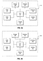
- FIG. 2a is a block diagram of an exemplary base station (BS), consistent with certain disclosed embodiments;
- FIG. 2b is a block diagram of an exemplary subscriber station (SS), consistent with certain disclosed embodiments;
- FIG. 2c is a block diagram of an exemplary mobile subscriber station (MSS), consistent with certain disclosed embodiments;
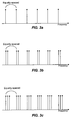
- FIG. 3a illustrates exemplary pilot signal locations, consistent with certain disclosed embodiments
- FIG. 3b illustrates exemplary pilot signal locations in a clustered scheme, consistent with certain disclosed embodiments
- FIG. 3c illustrates exemplary pilot signal locations in a clustered scheme, consistent with certain disclosed embodiments
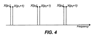
- FIG. 4 illustrates an exemplary phase difference of adjacent pilot signals, consistent with certain disclosed embodiments
- FIG. 5 is an exemplary graphical representation of the performance of a pilot signal pattern scheme, consistent with certain disclosed embodiments
- FIG. 6 is an exemplary graphical representation of the performance of a pilot signal pattern scheme, consistent with certain disclosed embodiments.
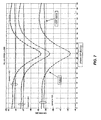
- FIG. 7 is an exemplary graphical representation of the performance of a pilot signal pattern scheme, consistent with certain disclosed embodiments.
- FIG. 8 illustrates phase differences in a rounding scheme, consistent with certain disclosed embodiments
- FIG. 9a is an exemplary two-dimensional illustration of pilot signal locations as a function of symbol and sub-carrier, consistent with certain disclosed embodiments.
- FIG. 9b is an exemplary two-dimensional illustration of pilot signal locations as a function of symbol and sub-carrier, consistent with certain disclosed embodiment
- FIG. 9c is an exemplary two-dimensional illustration of pilot signal locations as a function of symbol and sub-carrier, consistent with certain disclosed embodiments.
- FIG. 10 is an exemplary flow chart illustrating a method, consistent with certain disclosed embodiments.
- FIG. 1 is a block diagram of an exemplary wireless communication network 100 implementing OFDM, consistent with certain disclosed embodiments.
- wireless communication network 100 may include one or more communication devices, including one or more Base Stations (BS) 110, e.g., BS 110a, BS 110b, and BS 110c, one or more stationary subscriber stations (SS) 120, e.g., SS 120a and SS 120b, and one or more mobile subscriber stations (MSS) 130, e.g., MSS 130a, 130b, and 130c.
- BS Base Stations
- SS stationary subscriber stations
- MSS mobile subscriber stations
- BS 110 may be any type of communication device configured to transmit and/or receive data and/or communications based on one or more wireless standards, many of which are known in the art.
- BS 110 may be configured to communicate with one or more SSs 120, MSSs 130, other BSs 110, and/or other networks 150 using the communication protocols defined by any type of standard including, for example, the Institute of Electrical and Electronics Engineers (IEEE) 802.16 family of standards.
- IEEE Institute of Electrical and Electronics Engineers
- BS 110 may also be referred to as, for example, a Node-B, a base transceiver system (BTS), an access point (AP), etc.
- BTS base transceiver system
- AP access point
- BS 110 may function as a network coordinator, and may manage the collection, calculation, and communication of data and other network information.
- FIG. 2a is a block diagram of an exemplary BS 110 that may be used in exemplary wireless communication network 100 implementing OFDM, consistent with certain disclosed embodiments.
- BS 110 may include one or more of the following components: at least one central processing unit (CPU) 111 configured to execute one or more computer program instructions to perform various processes and methods, random access memory (RAM) 112 and read only memory (ROM) 113 configured to access and store information and computer program instructions, memory 114 to store data and information, one or more databases 115 to store tables, lists, or other data structures, one or more I/O devices 116, one or more interfaces 117, one or more antennas 118, etc.
- CPU central processing unit
- RAM random access memory
- ROM read only memory
- memory 114 to store data and information
- databases 115 to store tables, lists, or other data structures
- I/O devices 116 one or more interfaces 117, one or more antennas 118, etc.
- I/O devices 116 one or more interfaces 117, one or more antenna
- SS 120 may be any type of communication device configured to transmit and/or receive data and/or communications to and/or from one or more MSSs 130, other SSs 120, and/or BSs 110 using the communication protocols defined by one or more wireless standards including, for example, the IEEE 802.16 family of standards.
- SSs 120 may include, for example, servers, clients, mainframes, desktop computers, laptop computers, network computers, workstations, personal digital assistants (PDA), tablet PCs, scanners, telephony devices, pagers, cameras, musical devices, etc.
- PDA personal digital assistants
- FIG. 2b is block diagram of an exemplary SS 120 that may be used in exemplary wireless communication network 100 implementing OFDM, consistent with certain disclosed embodiments.
- SS 120 may include one or more of the following components: at least one central processing unit (CPU) 121 configured to execute one or more computer program instructions to perform various processes and methods, random access memory (RAM) 122 and read only memory (ROM) 123 configured to access and store information and computer program instructions, memory 124 to store data and information, one or more databases 125 to store tables, lists, or other data structures, one or more I/O devices 126, one or more interfaces 127, one or more antennas 128, etc.
- CPU central processing unit
- RAM random access memory
- ROM read only memory
- MSS 130 may include any type of wireless client device configured to communicate with BSs 110, SSs 120, and/or other MSSs 130 using one or more wireless communication standards including, for example, the IEEE 802.16 family of standards.
- MSSs 130 may include, for example, servers, clients, mainframes, desktop computers, laptop computers, network computers, workstations, personal digital assistants (PDA), tablet PCs, scanners, telephony devices, pagers, cameras, musical devices, etc.
- MSS 130 may be a mobile computing device.
- MSS 130 may be a "non-mobile" computing device located in a mobile environment (e.g., airplanes, watercraft, buses, multi-passenger vehicles, automobiles, etc.).
- FIG. 2c is a block diagram of an exemplary MSS 130 that may be used in exemplary wireless communication network 100 implementing OFDM, consistent with certain disclosed embodiments.
- MSS 130 may include one or more of the following components: at least one central processing unit (CPU) 131 configured to execute one or more computer program instructions to perform various processes and methods, random access memory (RAM) 132 and read only memory (ROM) 133 configured to access and store information and computer program instructions, memory 134 to store data and information, one or more databases 135 to store tables, lists, or other data structures, one or more I/O devices 136, one or more interfaces 137, one or more antennas 138, etc.
- CPU central processing unit
- RAM random access memory
- ROM read only memory
- memory 134 to store data and information
- databases 135 to store tables, lists, or other data structures
- I/O devices 136 one or more interfaces 137
- antennas 138 etc.
- BS 110 may serve as an intermediary between one or more SSs 120, MSSs 130, or BSs 110 and a network 150.
- Network 150 may be wired, wireless, or any combination thereof.
- Network 150 may include, for example, any combination of one or more WANs, LANs, intranets, extranets, Internet, etc.
- Each BS 110 may have a broadcast range within which that BS 110 may communicate with one or more SSs 120, MSSs 130, and/or other BSs 110.
- each SS 120 and MSS 130 may have broadcast ranges within which that SS 120 and MSS 130 may communicate with one or more other SSs 120, MSSs 130 and/or BSs 110. Broadcast ranges may vary due to power levels, location, interference (physical, electrical, etc.).
- each of BSs 110, SSs 120, and MSSs 130 may be configured to transmit and/or receive data.
- each BS 110 may also connect and communicate with one or more other BSs 110 using a line-of-sight, wireless link.
- wireless communication network 100 may provide two forms of wireless communication: a point-to-point (P2P) communication (e.g., between BS 110a and BS 110b) that operates at frequencies up to 66 GHz, and a point-to-multipoint (P2MP) communication (e.g., between BSs 110 and one or more SSs 120 and/or MSSs 130) that operates in the 2.0 to 11.0 GHz range.
- P2P point-to-point
- P2MP point-to-multipoint
- P2MP communication may include so-called Mobile Wi-Max (e.g., communication between BS 110 and one or more MSSs 130).
- Mobile Wi-Max is based on IEEE 802.16e-1005 and may operate in the 2.3 GHz, 2.5 GHz, 3.3 GHz, and 3.4 - 3.8 GHz spectrum bands.
- FIG. 3a is an exemplary one-dimensional illustration of pilot signal locations in an implementation in which each pilot signal is equidistant from the next pilot signal along the frequency-axis.
- FIG. 3b is an exemplary one-dimensional illustration of pilot signal locations in a clustered scheme having a cluster of 2 pilot signals (i.e., cluster(2)), consistent with certain disclosed embodiments.
- cluster(n) is a cluster that comprises n number of pilot signals, allocated to n number of adjacent sub-carriers, where the clusters are equally spaced from one another.
- a cluster(2) pilot signal pattern groups 2 individual pilot signals into one cluster, modulates each cluster onto adjacent subcarriers, and equally spaces the clusters.
- FIG. 3b is an exemplary one-dimensional illustration of pilot signal locations in an implementation in which each pilot signal is equidistant from the next pilot signal along the frequency-axis.
- FIG. 3b is an exemplary one-dimensional illustration of pilot signal locations in a clustered scheme having a cluster of 2 pilot signals (i.e
- 3c is an exemplary one-dimensional illustration of pilot signal locations in a clustered scheme having a cluster of 3 pilot signals (i.e., cluster(3)), consistent with certain disclosed embodiments.
- cluster(3) pilot signal pattern scheme groups 3 pilot signals into one cluster, modulates each cluster onto adjacent subcarriers, and equally spaces the clusters.
- different numbers of pilot signals may be grouped into a single cluster of a set of clusters in a manner similar to that discussed in connection with FIGs. 3b and 3c.
- FIGs. 3a, 3b, and 3c may be used in exemplary wireless communication network 100 implementing OFDM.
- the ICI due to relative movement of the base station, subscriber stations, and mobile subscriber stations, e.g., BSs 110, SSs 120, and MSS 130, may be self-cancelled and performance would be improved significantly.
- the number of pilot signals should be at least n times the channel length L.
- phase difference ⁇ of pilot signals is appropriately selected, ICI terms do not need to be cancelled by computational operations. Instead, the ICI may be self-cancelled.
- phase difference selection for CE performance may be a function of the channel length L and the cluster size n.
- FIG. 4 illustrates an exemplary method of phase difference ⁇ selection of adjacent pilot signals, consistent with certain disclosed embodiments.
- the method of FIG. 4 may be used in exemplary wireless communication network 100 implementing OFDM.
- ⁇ is selected to reduce the channel impulse response (CIR) mean square error (MSE).
- CIR channel impulse response
- MSE mean square error
- data close to pilot signal clusters can be modulated using different modulation and coding schemes according to system conditions.
- the closer the data is to a pilot signal cluster the greater the modulation.
- a quasi-static channel i.e., a channel which is assumed unchanged within the period of one OFDM symbol, there may be no ICI caused by Doppler spread. Therefore, the performances of CE may be the same in a conventional system as in a cluster(n) scheme if the number of pilot signals is at least n times the channel length.
- cluster(n) schemes provide ICI cancellation ability, while conventional schemes do not.
- MSE Performance Indicator Mean Square Error
- FIG. 5 is an exemplary graphical representation of a performance comparison between a scheme utilizing equally spaced pilot signals and a cluster(2) pilot pattern scheme such as may be used in an OFDM wireless communication system, consistent with certain disclosed embodiments.
- the x-axis of the exemplary graphical representation is the phase difference ⁇ of adjacent pilot signals within every cluster in units of ⁇ /32, and the ⁇ -axis is the CIR MSE measured in dB.
- the performance of the conventional scheme is substantially unaffected by the phase difference ⁇ , and the MSE is roughly equal to -23.5dB.
- the performance of the cluster(2) scheme is sensitive to the phase difference ⁇ .
- FIG. 6 is an exemplary graphical representation of the same performance comparison as in FIG. 5 except that the ICI is not self-cancelled, but is instead cancelled by additional cancellation hardware in the MSS.
- the results of the two cancellation schemes, respectively shown in FIGs. 5 and 6 are almost the same, demonstrating that, if the clustered pilot signal pattern is designed properly, extra computational complexity is not needed for ICI cancellation of CE.
- FIG. 7 is an exemplary graphical representation of a performance comparison between a scheme utilizing equally spaced pilot signals and a cluster(2) pilot pattern scheme such as may be used in an OFDM wireless communication system, consistent with certain disclosed embodiments.
- the 10dB MSE CIR performance improvement is not reduced as the speed decreases.
- FIG. 8 provides an exemplary illustration of pilot signal locations in frequency for equal-spaced pilot signal pattern schemes when the pilot number N p is selected as a minimum pilot number such as may be used in an OFDM wireless communication system, consistent with certain disclosed embodiments.
- a spacing ⁇ k between two pilot signal frequencies is N/L (i.e., FFT size/number of pilot signals). If the result of N/L is an integer, the scheme may have better performance. However, if N/L is not an integer, the determination of pilot signal spacing can significantly affect performance. In this illustration, for example, N/L is not an integer, and pilot locations are selected by rounding off the pilot signal location frequency determined by spacing ⁇ k to a nearest integer. As shown in FIG.
- pilot signal locations at pilot signal location frequencies determined by spacing ⁇ k to be 8.6, 12.9, 17.2, and 21.5 are rounded to normalized subcarrier spacing values of 8, 13, 17, and 22, respectively.
- the pilot signal number N P and location of pilot signals are adapted to the channel length L and ICI power (P ICI ) on the receiving side.
- P ICI ICI power
- a pilot signal scheme is chosen having equally spaced pilot signals, and a pilot signal number Np is chosen from L to N P, MAX , based on desired performance results.
- a pilot signal scheme is chosen having cluster(n) pilot signal location, and a pilot signal number N P is chosen from nL to N P, MAX , based on desired performance results.
- the minimum number of pilots desired to obtain a better CE performance is L.
- the channel varies slowly, and interpolation algorithms can be used for CE.
- a given number M total symbols are needed over L total pilot signals in order to maintain better CE performance as long as pilot signals are equally spaced in the time-axis and equally spaced in the frequency axis within each set of M symbols.
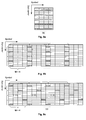
- FIGs. 9a, 9b, and 9c each illustrate an exemplary two-dimensional illustration of pilot signal locations as a function of symbol and sub-carrier such as may be used in an OFDM wireless communication system, consistent with certain disclosed embodiments.
- the different type of crosshatchings used in the block representations of FIG 9a-9c illustrate discrete user or transmitter pilots.
- FIG. 9a discloses an embodiment in which the pilot signals are equally spaced along the frequency and time domains. In this configuration, a discrete user or transmitter pilot is assigned to each subcarrier.
- FIG. 9b illustrates a cluster(n) embodiment in which the clusters of pilot signals are equally spaced along the frequency domain within a number of symbols M.
- a discrete user or subcarrier pilot is assigned a specific subcarrier and the subcarriers are equally spaced.
- pilots are equally spaced along the time domain at a distance of M symbols.
- FIG. 9c discloses a cluster(n) embodiment in which, as in FIG. 9b , the clusters of pilot signals are equally spaced along the time domain within a number of symbols M.
- the number of symbols M is equal to 4.
- FIG. 10 is an exemplary flow chart of a method 1000 for adaptively allocating pilot signals such as may be used in an OFDM wireless communication system, consistent with certain disclosed embodiments. More particularly, in view of the various pilot schemes described above, which may be adapted to different conditions encountered in a wireless communication system, method 1000 adapts an appropriate pilot signal pattern scheme based on the encountered conditions.
- Method 1000 commences with initialization, in which the pilot signal pattern scheme and number of pilot signals are unrestricted (step 1002).
- the maximum number of pilots N P, MAX is determined by the system requirement or, if applicable, an industry standard.
- An example of a system requirement could include a requested peak system throughput.
- a system throughput refers to the amount of data transferred through a system in a specific amount of time.
- the total number of pilots in a system may be constrained to enable the requested peak throughput. That is, in order to maintain a peak system throughput, there would be maximum number of the total symbols which can be allocated as pilot symbols, which corresponds to the maximum number of pilots N P, MAX .
- MSS 130 When MSS 130 receives a signal, it detects parameters of the message. For example, MSS 130 receives a signal and detects a channel length L, ICI power P ICI , channel coherence time CT, and/or other parameters related to these parameters. These parameters are fed back to the BS 110 (step 1004).
- BS 110 may be adapted to detect one or more of these parameters (e.g., L, P ICI , CT, etc.). For example, after receipt or acquisition of one or more of these parameters (e.g., L, P ICI , CT, etc.), BS 110 may determine if L is greater than a first channel length threshold L TH1 (step 1006). When L is greater than L TH1 , the pilot signal pattern scheme is set such that the pilot signals are equally-spaced, and the pilot number N P can be chosen from L to N P, MAN (step 1008). When L is less than or equal to L TH1 , BS 110 may determine whether P ICI is greater than a power threshold P TH (step 1010).
- L TH1 first channel length threshold
- the pilot signal pattern scheme is set such that the pilot signals are equally-spaced, and the pilot number N P can be chosen from L to N P, MAN (step 1008).
- BS 110 may determine whether P ICI is greater than a power threshold P TH (
- the pilot signal pattern scheme is set to provide equally-spaced pilot signals, and the pilot signal number N P is chosen from L to N P, MAX (1008).
- BS 110 may also determine if L is greater than a second channel length threshold L TH2 (step 1012). When L is less than or equal to the second channel length threshold L TH2 , a pilot signal pattern cluster(2) is selected, and the pilot signal number N P is set to 2L (step 1014). When L is greater than L TH2 , BS 110 may further determine, in turn, whether L is greater than channel length thresholds of L TH2 , L TH3 ...
- step 1018 L TH(n-1) to determine pilot signal cluster size. This continues until a cluster(n-1) is selected (step 1016) or a maximum pilot signal cluster size cluster(n) is reached (step 1018). If L is determined to be less than or equal to L TH(n-1) (1016), a pilot signal pattern cluster(n-1) is selected, and the pilot signal number N P is set to (n-1)L (step 1020). If L is determined to be greater than L TH(n-1) (step 1018), a pilot signal pattern cluster(n) is selected and the pilot signal number N P is set to nL. After the pilot pattern is selected in one of steps 1008, 1014, 1018, 1020, the pilot signals are allocated on the time axis according to the coherence time (CT). The method then returns to step 1004 to receive the next set of channel parameters.
- CT coherence time
- the threshold parameters for length and power are set according to system performance requirements.
- the base stations e.g., BS 110
Landscapes
- Engineering & Computer Science (AREA)
- Signal Processing (AREA)
- Computer Networks & Wireless Communication (AREA)
- Quality & Reliability (AREA)
- Power Engineering (AREA)
- Mobile Radio Communication Systems (AREA)
Applications Claiming Priority (2)
| Application Number | Priority Date | Filing Date | Title |
|---|---|---|---|
| US96055707P | 2007-10-03 | 2007-10-03 | |
| US12/204,422 US7782757B2 (en) | 2007-10-03 | 2008-09-04 | Adaptive pilot design for mobile system |
Publications (1)
| Publication Number | Publication Date |
|---|---|
| EP2045989A2 true EP2045989A2 (de) | 2009-04-08 |
Family
ID=40303500
Family Applications (1)
| Application Number | Title | Priority Date | Filing Date |
|---|---|---|---|
| EP08253058A Withdrawn EP2045989A2 (de) | 2007-10-03 | 2008-09-18 | Adaptiver Pilotentwurf für ein mobiles System |
Country Status (4)
| Country | Link |
|---|---|
| US (1) | US7782757B2 (de) |
| EP (1) | EP2045989A2 (de) |
| CN (1) | CN101404637B (de) |
| TW (1) | TWI368401B (de) |
Cited By (2)
| Publication number | Priority date | Publication date | Assignee | Title |
|---|---|---|---|---|
| WO2015112072A1 (en) * | 2014-01-27 | 2015-07-30 | Telefonaktiebolaget L M Ericsson (Publ) | Methods, network nodes, user equipment, and computer program products for adaptive radio link monitoring |
| CN105721364A (zh) * | 2014-12-03 | 2016-06-29 | 索尼公司 | 发送设备和接收设备 |
Families Citing this family (11)
| Publication number | Priority date | Publication date | Assignee | Title |
|---|---|---|---|---|
| JP4892547B2 (ja) * | 2006-03-17 | 2012-03-07 | パナソニック株式会社 | 無線通信基地局装置およびパイロット配置方法 |
| US8498249B2 (en) * | 2008-05-05 | 2013-07-30 | Mediatek Inc. | Method of network entry in OFDM multi-carrier wireless communications systems |
| US8203929B2 (en) * | 2008-10-09 | 2012-06-19 | Sony Corporation | Frame and data pattern structure for multi-carrier systems |
| TWI407738B (zh) * | 2009-04-24 | 2013-09-01 | Mediatek Inc | 載波分配方法和基地台 |
| US8897385B2 (en) * | 2009-10-20 | 2014-11-25 | Maxlinear, Inc. | Doppler estimator for OFDM systems |
| US8705642B2 (en) * | 2009-10-20 | 2014-04-22 | King Fahd University Of Petroleum And Minerals | Method for mitigating interference in OFDM communications systems |
| US8254510B2 (en) * | 2009-12-23 | 2012-08-28 | Industrial Technology Research Institute | Apparatus and method for inter-carrier interference cancellation |
| US10003998B2 (en) * | 2012-05-04 | 2018-06-19 | Qualcomm Incorporated | Systems and methods for reduced overhead in wireless communication systems |
| KR102194924B1 (ko) * | 2012-12-04 | 2020-12-24 | 엘지전자 주식회사 | 무선 통신 시스템에서 코히런스 시간 변화에 따른 참조 신호의 패턴 변경 방법 및 이를 위한 장치 |
| US9985802B2 (en) | 2014-10-31 | 2018-05-29 | Qualcomm Incorporated | Channel estimation enhancements |
| CN112332908B (zh) * | 2020-11-25 | 2021-10-22 | 中国科学技术大学 | 一种快速的nc-ofdm卫星通信比特功率分配方法 |
Family Cites Families (9)
| Publication number | Priority date | Publication date | Assignee | Title |
|---|---|---|---|---|
| US7548506B2 (en) * | 2001-10-17 | 2009-06-16 | Nortel Networks Limited | System access and synchronization methods for MIMO OFDM communications systems and physical layer packet and preamble design |
| KR100790114B1 (ko) | 2002-03-16 | 2007-12-31 | 삼성전자주식회사 | 직교주파수 분할다중 접속 시스템에서 적응적 파일럿반송파 할당 방법 및 장치 |
| KR100913874B1 (ko) | 2003-10-27 | 2009-08-26 | 삼성전자주식회사 | 직교주파수분할다중 시스템에서 부채널 간 간섭 제거 방법 |
| EP1542488A1 (de) | 2003-12-12 | 2005-06-15 | Telefonaktiebolaget LM Ericsson (publ) | Verfahren un vorrichtung zur Zuweisung von Kanaladaptierten Pilotsignalen |
| WO2005081439A1 (en) * | 2004-02-13 | 2005-09-01 | Neocific, Inc. | Methods and apparatus for multi-carrier communication systems with adaptive transmission and feedback |
| KR100594086B1 (ko) | 2005-01-04 | 2006-06-30 | 삼성전자주식회사 | 채널 추정을 위한 적응적 파일럿 할당 방법 및 장치 |
| US7660229B2 (en) | 2005-06-20 | 2010-02-09 | Texas Instruments Incorporated | Pilot design and channel estimation |
| EP1780968A1 (de) * | 2005-10-28 | 2007-05-02 | Alcatel Lucent | OFDM-basiertes Senden in einem zellularen Netz mit einer Trägerfrequenz mit einer Pilotsignal-angepaßten Kanalmultiplex-Struktur |
| US20090257342A1 (en) * | 2008-04-10 | 2009-10-15 | Media Tek Inc. | Resource block based pilot pattern design for 1/2 - stream mimo ofdma systems |
-
2008
- 2008-09-04 US US12/204,422 patent/US7782757B2/en active Active
- 2008-09-18 EP EP08253058A patent/EP2045989A2/de not_active Withdrawn
- 2008-09-26 TW TW097137210A patent/TWI368401B/zh not_active IP Right Cessation
- 2008-09-28 CN CN2008101687858A patent/CN101404637B/zh not_active Expired - Fee Related
Cited By (9)
| Publication number | Priority date | Publication date | Assignee | Title |
|---|---|---|---|---|
| WO2015112072A1 (en) * | 2014-01-27 | 2015-07-30 | Telefonaktiebolaget L M Ericsson (Publ) | Methods, network nodes, user equipment, and computer program products for adaptive radio link monitoring |
| CN105934973A (zh) * | 2014-01-27 | 2016-09-07 | 瑞典爱立信有限公司 | 用于自适应无线电链路监控的方法、网络节点、用户设备和计算机程序产品 |
| RU2643939C1 (ru) * | 2014-01-27 | 2018-02-07 | Телефонактиеболагет Лм Эрикссон (Пабл) | Способы, сетевые узлы, оборудование пользователя и компьютерные программные продукты для адаптивного мониторинга радиосоединения |
| US10517102B2 (en) | 2014-01-27 | 2019-12-24 | Telefonaktiebolaget Lm Ericsson (Publ) | Methods, network nodes, user equipment, and computer program products for adaptive radio link monitoring |
| EP3706463A1 (de) * | 2014-01-27 | 2020-09-09 | Telefonaktiebolaget LM Ericsson (publ) | Verfahren und benutzergerät zur adaptiven funkverbindungsüberwachung |
| RU2747271C2 (ru) * | 2014-01-27 | 2021-05-04 | Телефонактиеболагет Лм Эрикссон (Пабл) | Способы, сетевые узлы, оборудование пользователя и компьютерные программные продукты для адаптивного мониторинга радиосоединения |
| CN105721364A (zh) * | 2014-12-03 | 2016-06-29 | 索尼公司 | 发送设备和接收设备 |
| EP3229427A4 (de) * | 2014-12-03 | 2018-08-15 | Sony Corporation | Übertragungsvorrichtung und empfangsvorrichtung |
| CN105721364B (zh) * | 2014-12-03 | 2021-04-06 | 索尼公司 | 发送设备和接收设备 |
Also Published As
| Publication number | Publication date |
|---|---|
| TW200917691A (en) | 2009-04-16 |
| CN101404637A (zh) | 2009-04-08 |
| US7782757B2 (en) | 2010-08-24 |
| CN101404637B (zh) | 2011-07-27 |
| TWI368401B (en) | 2012-07-11 |
| US20090092194A1 (en) | 2009-04-09 |
Similar Documents
| Publication | Publication Date | Title |
|---|---|---|
| US7782757B2 (en) | Adaptive pilot design for mobile system | |
| US8064328B2 (en) | Channel estimation device | |
| US8345602B2 (en) | Wireless communication system, transmitting device and receiving device | |
| US20190327043A1 (en) | System and method for common phase error and inter-carrier interference estimation and compensation | |
| US8483159B2 (en) | Method and apparatus for frequency offset compensation | |
| JP5302887B2 (ja) | キャリア間干渉を相殺する伝送方法及び伝送装置 | |
| US8374266B2 (en) | Iterative channel estimation method and apparatus for ICI cancellation in multi-carrier | |
| KR100922949B1 (ko) | 통신 시스템에서 신호 수신 방법 및 그 시스템 | |
| US20100303165A1 (en) | Pilot transmission and channel estimation for an ofdm system with excess delay spread | |
| US8107517B2 (en) | Average-tap energy based thresholding for channel estimation in multi antenna systems | |
| US9197476B2 (en) | Channel estimation in OFDM transmission system and method | |
| CN108924943A (zh) | 基于窄带物联网随机接入信道的最大相关估计检测方法 | |
| US20090168908A1 (en) | Apparatus and method for estimating delay spread of multi-path fading channel in ofdm system | |
| US8036190B2 (en) | Methods and devices for allocating data in a wireless communication system | |
| CN107154907A (zh) | 基于滤波的信号发送、接收方法及相应的发射机与接收机 | |
| JP3794622B2 (ja) | 受信装置、受信方法、プログラム、ならびに、情報記録媒体 | |
| JP2009528754A (ja) | Ofdmシステムにおけるチャネルのコヒーレンス帯域幅に基づくガードインターバル長選択 | |
| US20080212697A1 (en) | Doppler Dependent Power Control and Sub-Carrier Allocation in ofdm Multiple Access Systems | |
| Zhang et al. | A differential OFDM approach to coherence time mitigation in DSRC | |
| Das et al. | Variable sub-carrier bandwidths in OFDM systems | |
| Nguyen-Duy-Nhat et al. | On the effect of phase noise and time-selective channel on OFDM transmission: SINR analysis | |
| CN100563230C (zh) | 一种干扰检测方法 | |
| Das et al. | Dynamically adaptive bandwidth for sub carriers in OFDM based wireless systems | |
| KR20110112567A (ko) | 무선통신 시스템에서 채널추정 장치 및 방법 | |
| KR101710912B1 (ko) | 잡음 전력 측정 방법 및 장치 |
Legal Events
| Date | Code | Title | Description |
|---|---|---|---|
| PUAI | Public reference made under article 153(3) epc to a published international application that has entered the european phase |
Free format text: ORIGINAL CODE: 0009012 |
|
| AK | Designated contracting states |
Kind code of ref document: A2 Designated state(s): AT BE BG CH CY CZ DE DK EE ES FI FR GB GR HR HU IE IS IT LI LT LU LV MC MT NL NO PL PT RO SE SI SK TR |
|
| AX | Request for extension of the european patent |
Extension state: AL BA MK RS |
|
| STAA | Information on the status of an ep patent application or granted ep patent |
Free format text: STATUS: THE APPLICATION IS DEEMED TO BE WITHDRAWN |
|
| 18D | Application deemed to be withdrawn |
Effective date: 20140401 |