EP2045451A2 - Dispositif d'isolation d'un compensateur - Google Patents
Dispositif d'isolation d'un compensateur Download PDFInfo
- Publication number
- EP2045451A2 EP2045451A2 EP08017289A EP08017289A EP2045451A2 EP 2045451 A2 EP2045451 A2 EP 2045451A2 EP 08017289 A EP08017289 A EP 08017289A EP 08017289 A EP08017289 A EP 08017289A EP 2045451 A2 EP2045451 A2 EP 2045451A2
- Authority
- EP
- European Patent Office
- Prior art keywords
- compensator
- insulating
- pipe
- insulating material
- tube
- Prior art date
- Legal status (The legal status is an assumption and is not a legal conclusion. Google has not performed a legal analysis and makes no representation as to the accuracy of the status listed.)
- Granted
Links
Images


Classifications
-
- F—MECHANICAL ENGINEERING; LIGHTING; HEATING; WEAPONS; BLASTING
- F01—MACHINES OR ENGINES IN GENERAL; ENGINE PLANTS IN GENERAL; STEAM ENGINES
- F01N—GAS-FLOW SILENCERS OR EXHAUST APPARATUS FOR MACHINES OR ENGINES IN GENERAL; GAS-FLOW SILENCERS OR EXHAUST APPARATUS FOR INTERNAL-COMBUSTION ENGINES
- F01N13/00—Exhaust or silencing apparatus characterised by constructional features
- F01N13/14—Exhaust or silencing apparatus characterised by constructional features having thermal insulation
-
- F—MECHANICAL ENGINEERING; LIGHTING; HEATING; WEAPONS; BLASTING
- F01—MACHINES OR ENGINES IN GENERAL; ENGINE PLANTS IN GENERAL; STEAM ENGINES
- F01N—GAS-FLOW SILENCERS OR EXHAUST APPARATUS FOR MACHINES OR ENGINES IN GENERAL; GAS-FLOW SILENCERS OR EXHAUST APPARATUS FOR INTERNAL-COMBUSTION ENGINES
- F01N13/00—Exhaust or silencing apparatus characterised by constructional features
- F01N13/18—Construction facilitating manufacture, assembly, or disassembly
- F01N13/1805—Fixing exhaust manifolds, exhaust pipes or pipe sections to each other, to engine or to vehicle body
- F01N13/1811—Fixing exhaust manifolds, exhaust pipes or pipe sections to each other, to engine or to vehicle body with means permitting relative movement, e.g. compensation of thermal expansion or vibration
- F01N13/1816—Fixing exhaust manifolds, exhaust pipes or pipe sections to each other, to engine or to vehicle body with means permitting relative movement, e.g. compensation of thermal expansion or vibration the pipe sections being joined together by flexible tubular elements only, e.g. using bellows or strip-wound pipes
-
- F—MECHANICAL ENGINEERING; LIGHTING; HEATING; WEAPONS; BLASTING
- F01—MACHINES OR ENGINES IN GENERAL; ENGINE PLANTS IN GENERAL; STEAM ENGINES
- F01N—GAS-FLOW SILENCERS OR EXHAUST APPARATUS FOR MACHINES OR ENGINES IN GENERAL; GAS-FLOW SILENCERS OR EXHAUST APPARATUS FOR INTERNAL-COMBUSTION ENGINES
- F01N13/00—Exhaust or silencing apparatus characterised by constructional features
- F01N13/18—Construction facilitating manufacture, assembly, or disassembly
- F01N13/1805—Fixing exhaust manifolds, exhaust pipes or pipe sections to each other, to engine or to vehicle body
- F01N13/1827—Sealings specially adapted for exhaust systems
-
- F—MECHANICAL ENGINEERING; LIGHTING; HEATING; WEAPONS; BLASTING
- F16—ENGINEERING ELEMENTS AND UNITS; GENERAL MEASURES FOR PRODUCING AND MAINTAINING EFFECTIVE FUNCTIONING OF MACHINES OR INSTALLATIONS; THERMAL INSULATION IN GENERAL
- F16L—PIPES; JOINTS OR FITTINGS FOR PIPES; SUPPORTS FOR PIPES, CABLES OR PROTECTIVE TUBING; MEANS FOR THERMAL INSULATION IN GENERAL
- F16L59/00—Thermal insulation in general
- F16L59/14—Arrangements for the insulation of pipes or pipe systems
- F16L59/16—Arrangements specially adapted to local requirements at flanges, junctions, valves or the like
- F16L59/21—Arrangements specially adapted to local requirements at flanges, junctions, valves or the like adapted for expansion-compensation devices
Definitions
- the invention relates to an insulating device of a compensator of a pipeline according to the features indicated in the preamble of patent claim 1.
- Such an insulating device is known, which is designed for an exhaust pipe of an internal combustion engine.
- the pipeline contains several compensators and, together with the compensators, is surrounded by an isolator device.
- the compensators are used primarily for length compensation in the event of temperature changes as a result of the hot exhaust gas flowing through the pipeline. Furthermore, by means of the compensators relative movements and / or pivoting of the remaining pipe parts can be compensated transversely and / or radially to the longitudinal axis of the pipeline.
- the present invention seeks to avoid the aforementioned disadvantages and with a low design effort, the insulating device to further develop such that an optimized insulation effect can be achieved and ensured for a long service life.
- the insulating device should require little manufacturing and / or assembly effort and be easily adaptable to the particular conditions of use and / or the operational requirements.
- the insulating device should be able to be produced in a simple manner and contain easily manageable and / or components to be joined together.
- the insulating device should be connected in a simple manner with the pipe compensator and / or the pipeline and / or have a high stability and fatigue strength.
- the insulating device according to the invention is characterized by a simple structural design and is preferably made entirely of metal, both the inner shell and the outer shell and in particular also arranged within the outer shell insulating material.
- the insulating device or at least a part thereof is on the one hand defined on one of the pipe parts and on the other hand designed to be movable relative to the pipe compensator and / or arranged.
- the insulating device is designed according to the invention as an insulating compensator surrounding the tube compensator and preferably reaches a hot medium such as exhaust gas, steam, pasty material or liquid for use.
- the insulating device is tubular and surrounds the tube compensator and optionally at least partially the axially spaced tube portions, wherein between the insulating device and the tube compensator, an annular cavity is present or the insulating device is arranged directly on the tube compensator.
- the outer jacket provided according to the invention is advantageously sealed, in particular liquid-tight, so that foreign substances can not penetrate into the insulating material from the outside. This also applies to compounds with subsequent to the insulating compensator insulation and / or with the pipe parts.
- the inner and outer sheath are preferably made of sheet metal or metal foil, in particular of stainless steel, wherein at least the free outer surface of the outer sheath may be appropriately microstructured and / or macrostructured or optionally also made substantially smooth.
- the outer sheath is at least partially, but preferably overall, flexible and / or contains a wave-like structure, profiling or embossing such that the insulating device as well as the pipe compensator can compensate mainly changes in length of the connected pipe.
- the insulating material consists and / or preferably contains fibers or wires, in particular stainless steel wool.
- the insulating material consist of films or sheets or contain those which have at least partially predetermined defined distances from each other, especially by profiling, such as waves or imprints.
- the insulating material is as well as the outer and inner shells purely metallic and thus easily recyclable.
- the insulating device according to the invention is fixed to a pipe part and / or connected thereto.
- the insulating compensator is essentially free and independent or at least so flexible that relative movements of the two tube parts relative to each other, especially in the axial direction, but also in the axial direction. or angular misalignment can be safely absorbed.
- the two axially spaced apart pipe parts may be components of the flow through of a hot medium pipe or components of the particular commercially available pipe compensator may be, the pipe parts of such a pipe compensator in a known manner, in particular by welded joints and / or sleeve joints and / or flange connections are tightly and firmly connected.
- the pipe parts and / or the connected pipe are preferably surrounded by the insulating device or by further insulating devices in a preferred manner.
- the insulating device and in particular its insulating material is designed primarily for thermal insulation, wherein additionally or alternatively the training may be provided for sound insulation.
- the inner jacket which preferably surrounds the tube compensator at a predetermined distance, is designed to be substantially rigid for supporting the insulating material and the surrounding outer jacket, which consists in particular of a thin metal foil.
- the rigidly formed inner shell is fastened with its one end on the one tube part, while the other the second tube part facing and / or associated end of the inner shell as well as the local ends of the insulating material and the outer shell with respect to the second tube part are free, so that relative movements of the second pipe part with respect to the first-mentioned pipe part have substantially no effect on the insulating compensator.
- the outer shell is fixed by means of fastening and / or support bodies with the respective ends on the two tube parts, wherein especially the outer sheath is at least partially flexible, in particular designed as a corrugated tube or corrugated hose or similar structures or Contains profilings to compensate for relative movements of the axially spaced tube parts can.
- the insulating device according to the invention can not be used solely for use or in combination with internal combustion engines or exhaust gas pipelines, but according to the invention also for arbitrarily designed aggregates, such as turbines or hot gas blowers or heat exchangers or extruders for plastics processing , wherein the hot media may be gaseous, vaporous, pasty or liquid.
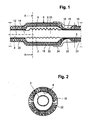
- Fig. 1 and 2 show sections in an axial or radial sectional plane of the pipe with a compensator 2, which is exemplarily as a flexible corrugated pipe or bellows, in particular made of metal, and with the metallic pipe parts 4, 5 in a known manner, in particular by means of welded joints tightly and firmly connected.
- the pipe parts 4, 5 may be components of the not shown, left and right according to drawing subsequent pipeline or connecting pieces of commercially available compensators to make a tight and firm connection with the other components of the pipeline, such as by welding, Flansch- or socket joints.
- the compensator 2, which is referred to below as a tube compensator is surrounded by a further compensator 6, which is referred to below as an insulating compensator.
- the insulating compensator 6 includes a preferably metallic inner jacket 8, which surrounds the tube compensator 2 at a radial distance 10 to form an annular cavity 9.
- the distance 10 is dimensioned according to the requirements and / or conditions of use and / or movements of the pipe part 5 to the longitudinal axis 12 of the pipe part 4.
- the inner jacket 8 is bent radially inwards and, by means of a dash-dotted line connection 14, in particular welded connection, preferably tightly and / or firmly connected to the tube part 4.
- the metallic inner shell 8 is preferably formed in two parts to facilitate the manufacture and / or assembly. At the longitudinal edges of the two parts of the inner shell 8, for example, flanges for connecting said parts are present. It is understood that the inner shell 8, in particular in Dependence of the size or the diameter of the tube compensator 2 can also be constructed of more than two parts.
- the tube part 4, like the inner jacket 8: of the tubular Isoller compensator 6, is surrounded by insulating material or insulating material 18, the inner jacket 8 ensuring the radial support of the insulating material 18 in the area of the tube compensator 2.
- the insulating material 18 is surrounded on the outside by a metallic outer jacket 20, 22.
- the outer shells 20, 21 are integrally formed in a preferred manner, according to the invention, the determination of the insulating compensator 2 takes place directly by means of the connection 14 on the pipe part 4.
- the tube part 5 is likewise surrounded by insulating material or insulating material 19, which radially outside is likewise surrounded by a metallic outer jacket 21.
- the outer casing 21 is guided radially inwards and advantageously connected to the pipe part 5, preferably by welding.
- the insulating material 18, 19 and the insulation as well as the inner shell 8 and the outer shells 20, 21, 22 made of metallic materials and thus a full metal insulation of the tube compensator 2 as well as the entire pipeline, which also from is surrounded by a full metal insulation is created, which is achieved in a particularly advantageous manner, a simple disposal and recycling.
- a protective cap 24 is arranged, which is fixed on the outer casing 21 of the insulation of the pipe part 5.
- the protective cap 24 By means of the protective cap 24, the penetration of foreign substances, in particular flammable diesel fuel, prevented.
- the installation position of the pipe parts 4, 5 with the pipe compensator 2 with respect to the horizontal predetermined such that such foreign matter on the outside of the protective cap 24 can flow without penetrating into the cavity 9 and the terminal portion 23 and / or the insulating material to be able to.
- Fig. 3 shows a perspective view of the insulating device or the insulating compensator 6 with the drawn in the region of the free end 15 of the tube compensator radially inward metallic outer shell 22, which does not directly surrounding the second tube part to form a gap, but its metallic outer jacket 21.
- the protective cap 24 is hereby shown in the assembled state, before this in Direction of the arrow 26 is pushed over the free end 15 of the insulating compensator 6, according to Fig. 2 positioned and fixed on the outer shell 21, in particular by welding and / or spot welding.
- Fig. 4 shows the insulating device similar Fig. 1 , In the upper part of the mounting state is shown, without the insulating material, while in the lower part of the insulating material 18 on the inner shell 8 of the insulating compensator 6 and the tube part 4 and on that of the outer shell 22 is arranged.
- the inner jacket 8 of the insulating compensator 6 is fastened by means of the connection 14 on the pipe part 4, wherein according to the invention a fixed bearing of the insulating compensator 6 is provided on the pipe part 4.
- the gap 16 is present between this and the pipe part 5, so that the insulating compensator 6 is basically independent of relative movements of the pipe parts 4, 5.
- the pipe part 5 in the region of the free end 15 is thus basically a loose bearing available, which allows relative movements of the pipe part 5 with respect to the insulating compensator 6, especially over a much larger circumferential angular range of the crescent-shaped gap 16 is present. Excessive or even unacceptable stresses of the insulating compensator 6 are thus largely avoided even at a fairly large radial and / or angular misalignment.
- Fig. 5 shows an alternative embodiment, according to which both the inner shell 8 and the outer shell 22 of the Isoller compensator 6 are connected in an advantageous manner together with the pipe part 4.
- the dashed line indicates the insulation 18 of the pipe part 4 which immediately adjoins the insulating compensator 6.
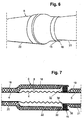
- Fig. 6 shows a perspective view of an embodiment in which the radially inwardly bent free end 15 of the insulating compensator 6 engages over the outer casing 21 of the second tube part.
- the basis of Fig. 4 explained annular gap 16 is thus at the free end 15 between the existing there part of the inner shell of the Isoller-compensator 6 and the outer shell 21 is present.
- analogously to Fig. 1 advantageously also be provided here a protective cap.
- Fig. 7 an embodiment is shown with an insulating compensator 6, at the free end 15 of the inner shell 8 is bent radially outward and is firmly connected to the outer shell 22, in particular by welding.
- the outer shell 21 of the pipe part 5 surrounded insulation is, however, bent radially inwardly in this area and connected to the outer wall of the pipe part 5, in particular by welding.
- the free end 15 preferably axially overlaps the inwardly bent portion 34 of the outer shell 21 such that between the free end 15 and the radially inwardly bent end portion of the outer shell 21, an annular space 30 is present.
- a flexible sealing element 32 is arranged, which rests sealingly on the one hand radially on the outside of the inner casing 8 and on the other hand radially inwardly on the outer casing 21.
- the end portion 34 of the outer shell 21 is bent radially outward, while in the region of the free end 15, the overlapping end portion 36 of the inner shell 8 is bent radially inwardly, whereby the flexible sealing element 32 is set reliably in the annular space 30.
- the axial distance between the end portions 34, 36 is preferably greater than the axial length of the sealing element 32, so that relative movements of the insulating compensator 6 with respect to the tubular member 5 can be made without further ado and especially without stress of the insulating compensator 6.
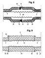
- the insulating compensator 6 according to Fig. 8 is formed in two parts, wherein according to the drawing left part 38 is fixedly connected to the pipe part 4 and that analogous to the embodiment of Fig. 1 while the right Kompensatorteil 39 with the second tube part 5 is also firmly connected.
- Analogous to the embodiment according to Fig. 7 are bent at the end portions 34, 36, the ends of the respective inner shell 8 and the associated outer shell 22 and together to define the sealing element 32 in the annular space 30 connected to each other.
- Fig. 9 shows a particular embodiment of the insulating compensator 6 with the formed in particular as a corrugated tube and / or flexible metallic outer shell 22, preferably made of stainless steel. Between the formed in particular as a corrugated tube tube compensator 2 and the corrugated tube or flexible outer casing 22, the insulating material or the insulating material 18 is arranged. It is of particular importance that the insulating material 18 which surrounds the tube compensator 2, as well as this is flexible.
- the tube part 4 and on the tube part 5 substantially radially outwardly extending body 42, 43 arranged and fixed, on which the flexible metallic outer shell 22 in the form of Corrugated tube placed and / or supported and / or secured in a suitable manner.
- the tubular outer shell 22 is thus fixed at its two axial ends indirectly via the body 42 and 43 on the one hand on the one tube part 4 and on the other hand on the two tube part 5 and / or connected thereto.
- the bodies 42, 43 are in particular designed as annular bodies and the fastening of the respective ends of the flexible outer sheath or corrugated tube 22 takes place in particular by welding or by means of pipe clamps or the like.
- the bodies 42, 43 associated ends of the outer shells 20, 21 with the ends of the corrugated tube 22, preferably also with the bodies 42, 43, in particular by welding and / or flanging, connected.
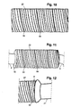
- Fig. 10 shows a side view of the formed as a corrugated tube outer jacket 22 of the insulating compensator.
- the outer shell 22 is formed as a helix of a corrugated sheet-metal strip, wherein the lying in the substantially cylindrical helix longitudinal edges of the original straight sheet metal strip are preferably sealed together and have a corresponding helical connecting portion 44, in particular in the form of a weld.
- the sheet metal strip originally extending in a straight longitudinal direction before forming into a helix is corrugated transversely to the longitudinal direction, suitably rounded troughs and wave heights being present transversely to the longitudinal direction. After winding to a Spiral run the troughs and wave heights at a corresponding angle inclined to the longitudinal axis of the outer shell or after the manufacture of the insulating compensator.
- insulating compensator 6 is shown with the formed as a corrugated tube outer shell 22 after assembly to the tube compensator and on the pipe parts 4, 5.
- the explained and connected to the pipe part 4 body 42 is partially visible.
- Fig. 12 shows partially the insulating compensator 6 with the formed as a corrugated tube outer shell 22, and that after the final installation of the insulation of the second tube part with the surrounding insulation and the outer shell 21.
- the insulating compensator 6 associated end of the metallic outer shell 21 is radial bent outward and / or expanded such that the end of the corrugated tube 22 is overlapped, wherein preferably there the outer jacket 21 is connected to the end of the corrugated tube 22 by welding.
- FIG. 13 to 15 Variants of the annular body 42, 43 are shown for fixing the flexible outer jacket 22 of the insulating compensator 6, wherein the insulating material is omitted for the sake of simplicity.
- the semicircular ring segments 46, 47 are suitably laser or stamped parts, which project in the radial direction from the pipe part 4 to the outside, in Fig. 13 shown below ring body 42 'is made of an L-profile and formed in particular as a stamped or pressed part.
- the ring body 42 ' is also formed at least in two parts, wherein in Fig. 15 the one ring segment 49 in the direction C according to Fig. 13 is shown.
- the ring body 42 'or its respective ring segment 49 has a bend 50 radially outwards such that the outer jacket of the Isoller compensator, which is designed in particular as a corrugated tube, ends with its end in the bend formed by the bend and at the other end the outer shell open space 52 engages.
- the outer jacket of the Isoller compensator which is designed in particular as a corrugated tube
- annular body 43 ' is formed as a U-profile, wherein in preferably in turn two semicircular ring segments are provided. Also in this variant, the coaxial to the pipe part 5 and resting on this inner leg 54 is connected in an advantageous manner with the pipe part 5 by resistance welding.
- the formed as a U-shaped ring body or its semi-circular ring segments are in turn formed as stamped or pressed parts.
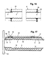
- Fig. 16 shows embodiments of the definition and / or attachment of the flexible, in particular designed as a corrugated tube outer sheath 22 of the insulating compensator 6.
- Top left the attachment of the end of the outer sheath 22 is shown on the outer edge of the ring body 42 by means of compression and resistance welding.
- the fastening is carried out by flipping the end of the outer jacket 22 radially inwards and side resistance welding and / or spot welding.
- the annular body 43 engages with its outer edge in a radially inwardly open trough at the end of the outer shell 22.
- a metallic clamp 56 is provided, wherein the ring body 43 is arranged radially inward in the same radial plane.
- the annular clamp 56 engages around and / or engages over the resting on the outer edge of the annular body 43 and / or supported by this end of the outer shell 22 and by means of the radially inwardly open clamp 56 thus the insulating compensator 6 is fixed by pressing on the pipe part 5 ,
- the insulating material 18, 19 surrounds the tube compensator 2 and the tube parts 4, 5 directly, wherein in the lower part of the drawing, the mounting state after the application of the insulating material 18, 19 is shown.
- On the insulating material 18, 19 are two support rings 58 axially spaced, and suitably in the areas above the pipe parts 4, 5, respectively.
- the support rings 58 include radially outwardly directed beads 60 and two laterally of the bead 60 and arranged to the pipe parts 4, 5 substantially coaxial leg 62.
- the metallic outer shells 20 and the other flexible and in particular formed as a corrugated tube or bellows outer shell 22 is connected, in particular by welded joints, as indicated by the dotted lines.
- the compound with the outer surface of the insulating material 18, 19 is produced by means of said compounds, in particular welded joints, whereby in a particularly advantageous manner a secure axial fixing of the support rings 58 is achieved.
- a flange 64 is further connected, which is provided for connection to the pipeline.
- FIG. 18 illustrated embodiment substantially corresponds to the according Fig. 17
- the two outer shells 20, 21 have overlapping end portions 66, 67, which are preferably arranged substantially in the middle of the longitudinal extent of the tube compensator 2.
- These end portions 66 and 67 are formed as intermeshing waves or beads and form the flexible outer shell 22.
- the thus formed and axially overlapping beads are thus relaxation beads or generally flexible profiling of the outer shell 22.
- an annular gap 68 is present, which in the axial direction corresponding to the contours of the end portions 66, 67 is formed in particular wave-shaped.
- the annular gap 68 due to the intermeshing waves or beads in the manner of a labyrinth seal is effective, in addition, relative movements of the outer shells 20, 21 are basically possible without contact.
- the size of the annular gap 68, both in the axial direction, is predetermined according to the conditions of use and the expected relative movements of the pipe parts 4, 5.
- the radial dimensions of the beads and waves as well as their axial distances are adapted to the requirements.
- the size of the annular gap can go to zero in the context of the invention, wherein the flexibility of the outer shell 22 by the training, in particular material thickness and / or shaping of the profilings or waves or beads, is specified.
Landscapes
- Engineering & Computer Science (AREA)
- General Engineering & Computer Science (AREA)
- Mechanical Engineering (AREA)
- Chemical & Material Sciences (AREA)
- Combustion & Propulsion (AREA)
- Thermal Insulation (AREA)
- Rigid Pipes And Flexible Pipes (AREA)
Applications Claiming Priority (1)
| Application Number | Priority Date | Filing Date | Title |
|---|---|---|---|
| DE202007013741 | 2007-10-01 |
Publications (3)
| Publication Number | Publication Date |
|---|---|
| EP2045451A2 true EP2045451A2 (fr) | 2009-04-08 |
| EP2045451A3 EP2045451A3 (fr) | 2010-01-27 |
| EP2045451B1 EP2045451B1 (fr) | 2012-12-12 |
Family
ID=40158008
Family Applications (1)
| Application Number | Title | Priority Date | Filing Date |
|---|---|---|---|
| EP20080017289 Active EP2045451B1 (fr) | 2007-10-01 | 2008-10-01 | Dispositif d'isolation d'un compensateur |
Country Status (2)
| Country | Link |
|---|---|
| EP (1) | EP2045451B1 (fr) |
| DE (1) | DE202008013021U1 (fr) |
Families Citing this family (7)
| Publication number | Priority date | Publication date | Assignee | Title |
|---|---|---|---|---|
| DE102010021334B4 (de) * | 2010-05-22 | 2013-03-28 | Boa Balg- Und Kompensatoren-Technologie Gmbh | Verfahren zur Herstellung eines Wärmetauschers und Wärmetauscher |
| DE102012200396A1 (de) * | 2012-01-12 | 2013-07-18 | Witzenmann Gmbh | Thermisch isoliertes flexibles Leitungselement |
| DE102012216097B4 (de) * | 2012-09-12 | 2024-11-28 | Witzenmann Gmbh | Entkoppelelement |
| DE102014100296A1 (de) * | 2014-01-13 | 2015-07-16 | Witzenmann Gmbh | Flexibles Leitungselement mit Isolierung |
| DE102017127069B4 (de) * | 2017-11-17 | 2019-08-08 | Dr. Ing. H.C. F. Porsche Aktiengesellschaft | Anordnung eines Abgasrohres und einer Integraldämmung für das Abgasrohr |
| EP4235001B1 (fr) * | 2022-02-25 | 2024-10-16 | MAGNA Energy Storage Systems GesmbH | Conduit de transfert thermiquement isolé pourvu d'élément d'accouplement |
| DE102022125936A1 (de) | 2022-10-07 | 2024-04-18 | Westfalia Metal Hoses Gmbh | Anschlussverbindung zwischen einem Rohrwellschlauch und einem Rohrleitungssystem |
Citations (5)
| Publication number | Priority date | Publication date | Assignee | Title |
|---|---|---|---|---|
| EP0403943A1 (fr) | 1989-06-21 | 1990-12-27 | Isolfeu Ag Zurich | Isolation thermique pour compensateurs de tuyaux |
| EP0568835A1 (fr) | 1992-05-05 | 1993-11-10 | Witzenmann GmbH Metallschlauch-Fabrik Pforzheim | Elément de compensation pour tuyauteries à enveloppe en matière plastique |
| EP1134478A2 (fr) | 2000-02-26 | 2001-09-19 | Thermamax Hochtemperaturdämmung GmbH | Dispositif d'isolation |
| DE102004044172A1 (de) | 2003-09-23 | 2005-04-14 | Ge Jenbacher Gmbh & Co Ohg | Brennkraftmaschine |
| US20060032218A1 (en) | 2002-11-28 | 2006-02-16 | Hutchinson | Decoupling hose for a motor vehicle exhaust system |
Family Cites Families (6)
| Publication number | Priority date | Publication date | Assignee | Title |
|---|---|---|---|---|
| DE3307457A1 (de) * | 1983-03-03 | 1984-09-06 | Hans Skodock Spezialfabrik für nahtlose Metallschläuche GmbH & Co KG, 3000 Hannover | Vorrichtung zum elastischen verbinden zweier mit kunststoff ummantelter rohrleitungen |
| DE8522123U1 (de) * | 1985-08-01 | 1985-09-26 | Pipeline Engineering Gesellschaft für Planung, Bau- und Betriebsüberwachung von Fernleitungen mbH, 4300 Essen | Wärmeisolierter Rohrleitungsabschnitt mit einem Dehnungskompensator zwischen zwei Rohrbögen |
| DE3540231A1 (de) * | 1985-11-13 | 1987-05-14 | Messerschmitt Boelkow Blohm | Kombinierter schall- und schwingungsdaempfer |
| GB9313419D0 (en) * | 1993-06-29 | 1993-08-11 | Wes Technology Inc | Bellows expansion joint |
| DE4414738A1 (de) * | 1994-04-27 | 1995-11-02 | Roth Technik Gmbh | Abgasanlage |
| AT414035B (de) * | 2003-01-24 | 2006-08-15 | Jenbacher Ag | Dämmeinrichtung zum zumindest teilweisen umfassen eines leitungssystems |
-
2008
- 2008-10-01 DE DE202008013021U patent/DE202008013021U1/de not_active Expired - Lifetime
- 2008-10-01 EP EP20080017289 patent/EP2045451B1/fr active Active
Patent Citations (5)
| Publication number | Priority date | Publication date | Assignee | Title |
|---|---|---|---|---|
| EP0403943A1 (fr) | 1989-06-21 | 1990-12-27 | Isolfeu Ag Zurich | Isolation thermique pour compensateurs de tuyaux |
| EP0568835A1 (fr) | 1992-05-05 | 1993-11-10 | Witzenmann GmbH Metallschlauch-Fabrik Pforzheim | Elément de compensation pour tuyauteries à enveloppe en matière plastique |
| EP1134478A2 (fr) | 2000-02-26 | 2001-09-19 | Thermamax Hochtemperaturdämmung GmbH | Dispositif d'isolation |
| US20060032218A1 (en) | 2002-11-28 | 2006-02-16 | Hutchinson | Decoupling hose for a motor vehicle exhaust system |
| DE102004044172A1 (de) | 2003-09-23 | 2005-04-14 | Ge Jenbacher Gmbh & Co Ohg | Brennkraftmaschine |
Also Published As
| Publication number | Publication date |
|---|---|
| EP2045451A3 (fr) | 2010-01-27 |
| DE202008013021U1 (de) | 2008-12-24 |
| EP2045451B1 (fr) | 2012-12-12 |
Similar Documents
| Publication | Publication Date | Title |
|---|---|---|
| EP2045451B1 (fr) | Dispositif d'isolation d'un compensateur | |
| DE102009025054B4 (de) | Turbinengehäuse | |
| EP0332853B1 (fr) | Jonction de conduite | |
| DE19722603C1 (de) | Leitungselement mit wenigstens zwei Bälgen und einem diese verbindenden Zwischenrohr | |
| DE69811547T2 (de) | Biegsame Verbindungsvorrichtung | |
| DE19901663A1 (de) | Rohrkupplung | |
| EP1048881B1 (fr) | Conduite de produit réfrigérant pour conditionneurs d'air | |
| DE102007016149A1 (de) | Metallschlauchanordnung mit Innen- und Außenschlauch | |
| EP4235001B1 (fr) | Conduit de transfert thermiquement isolé pourvu d'élément d'accouplement | |
| EP3118504B1 (fr) | Compensateur, en particulier pour applications sur vehicules automobiles | |
| DE3526481A1 (de) | Verbindung zweier rohrenden durch ein wellrohr | |
| DE2910429A1 (de) | Dehnungsverbindung fuer eine ein unter druck und unter hoher temperatur stehendes fliessfaehiges medium fuehrende rohrleitung | |
| EP2894312B1 (fr) | Élément de conduite flexible avec isolation | |
| DE102005047951B4 (de) | Ummantelte Druckleitung | |
| DE3804208C2 (fr) | ||
| DE69600074T2 (de) | Flexibles röhrenförmiges Verbindungselement, für die Abgasanlage eines Kraftfahrzeuges | |
| DE102012216097B4 (de) | Entkoppelelement | |
| EP1134478B1 (fr) | Dispositif d'isolation | |
| EP1783413B1 (fr) | Dispositif pour raccorder les bouts d'un tuyau métallique ondulé hélicoïdalement avec un embout | |
| EP2851533B1 (fr) | Élément de conduite flexible | |
| DE3445662A1 (de) | Anschlusshuelse an metallringwellschlauch | |
| DE102009049475B4 (de) | Kompensator für Rohrleitungen | |
| DE102019122012A1 (de) | Flexibles Leitungselement aus Metall | |
| DE20022457U1 (de) | Kältemittelleitung für Klimaanlagen | |
| DE3934755C2 (de) | Metallischer Hohlprofil-Dichtring, insbesondere für Kraftfahrzeug-Motoren |
Legal Events
| Date | Code | Title | Description |
|---|---|---|---|
| PUAI | Public reference made under article 153(3) epc to a published international application that has entered the european phase |
Free format text: ORIGINAL CODE: 0009012 |
|
| AK | Designated contracting states |
Kind code of ref document: A2 Designated state(s): AT BE BG CH CY CZ DE DK EE ES FI FR GB GR HR HU IE IS IT LI LT LU LV MC MT NL NO PL PT RO SE SI SK TR |
|
| AX | Request for extension of the european patent |
Extension state: AL BA MK RS |
|
| PUAL | Search report despatched |
Free format text: ORIGINAL CODE: 0009013 |
|
| AK | Designated contracting states |
Kind code of ref document: A3 Designated state(s): AT BE BG CH CY CZ DE DK EE ES FI FR GB GR HR HU IE IS IT LI LT LU LV MC MT NL NO PL PT RO SE SI SK TR |
|
| AX | Request for extension of the european patent |
Extension state: AL BA MK RS |
|
| 17P | Request for examination filed |
Effective date: 20100719 |
|
| 17Q | First examination report despatched |
Effective date: 20100819 |
|
| AKX | Designation fees paid |
Designated state(s): AT BE BG CH CY CZ DE DK EE ES FI FR GB GR HR HU IE IS IT LI LT LU LV MC MT NL NO PL PT RO SE SI SK TR |
|
| REG | Reference to a national code |
Ref country code: DE Ref legal event code: R079 Ref document number: 502008008855 Country of ref document: DE Free format text: PREVIOUS MAIN CLASS: F01N0007100000 Ipc: F16L0059210000 |
|
| RIC1 | Information provided on ipc code assigned before grant |
Ipc: F16L 59/21 20060101AFI20120531BHEP Ipc: F01N 13/18 20100101ALI20120531BHEP Ipc: F01N 13/14 20100101ALI20120531BHEP Ipc: F01N 13/10 20100101ALI20120531BHEP |
|
| GRAP | Despatch of communication of intention to grant a patent |
Free format text: ORIGINAL CODE: EPIDOSNIGR1 |
|
| GRAS | Grant fee paid |
Free format text: ORIGINAL CODE: EPIDOSNIGR3 |
|
| GRAA | (expected) grant |
Free format text: ORIGINAL CODE: 0009210 |
|
| AK | Designated contracting states |
Kind code of ref document: B1 Designated state(s): AT BE BG CH CY CZ DE DK EE ES FI FR GB GR HR HU IE IS IT LI LT LU LV MC MT NL NO PL PT RO SE SI SK TR |
|
| REG | Reference to a national code |
Ref country code: GB Ref legal event code: FG4D Free format text: NOT ENGLISH |
|
| REG | Reference to a national code |
Ref country code: CH Ref legal event code: EP |
|
| REG | Reference to a national code |
Ref country code: AT Ref legal event code: REF Ref document number: 588503 Country of ref document: AT Kind code of ref document: T Effective date: 20121215 |
|
| REG | Reference to a national code |
Ref country code: IE Ref legal event code: FG4D Free format text: LANGUAGE OF EP DOCUMENT: GERMAN |
|
| REG | Reference to a national code |
Ref country code: DE Ref legal event code: R096 Ref document number: 502008008855 Country of ref document: DE Effective date: 20130207 |
|
| PG25 | Lapsed in a contracting state [announced via postgrant information from national office to epo] |
Ref country code: FI Free format text: LAPSE BECAUSE OF FAILURE TO SUBMIT A TRANSLATION OF THE DESCRIPTION OR TO PAY THE FEE WITHIN THE PRESCRIBED TIME-LIMIT Effective date: 20121212 Ref country code: LT Free format text: LAPSE BECAUSE OF FAILURE TO SUBMIT A TRANSLATION OF THE DESCRIPTION OR TO PAY THE FEE WITHIN THE PRESCRIBED TIME-LIMIT Effective date: 20121212 Ref country code: ES Free format text: LAPSE BECAUSE OF FAILURE TO SUBMIT A TRANSLATION OF THE DESCRIPTION OR TO PAY THE FEE WITHIN THE PRESCRIBED TIME-LIMIT Effective date: 20130323 Ref country code: NO Free format text: LAPSE BECAUSE OF FAILURE TO SUBMIT A TRANSLATION OF THE DESCRIPTION OR TO PAY THE FEE WITHIN THE PRESCRIBED TIME-LIMIT Effective date: 20130312 Ref country code: SE Free format text: LAPSE BECAUSE OF FAILURE TO SUBMIT A TRANSLATION OF THE DESCRIPTION OR TO PAY THE FEE WITHIN THE PRESCRIBED TIME-LIMIT Effective date: 20121212 |
|
| REG | Reference to a national code |
Ref country code: NL Ref legal event code: VDEP Effective date: 20121212 |
|
| REG | Reference to a national code |
Ref country code: LT Ref legal event code: MG4D |
|
| PG25 | Lapsed in a contracting state [announced via postgrant information from national office to epo] |
Ref country code: GR Free format text: LAPSE BECAUSE OF FAILURE TO SUBMIT A TRANSLATION OF THE DESCRIPTION OR TO PAY THE FEE WITHIN THE PRESCRIBED TIME-LIMIT Effective date: 20130313 Ref country code: LV Free format text: LAPSE BECAUSE OF FAILURE TO SUBMIT A TRANSLATION OF THE DESCRIPTION OR TO PAY THE FEE WITHIN THE PRESCRIBED TIME-LIMIT Effective date: 20121212 Ref country code: SI Free format text: LAPSE BECAUSE OF FAILURE TO SUBMIT A TRANSLATION OF THE DESCRIPTION OR TO PAY THE FEE WITHIN THE PRESCRIBED TIME-LIMIT Effective date: 20121212 |
|
| PG25 | Lapsed in a contracting state [announced via postgrant information from national office to epo] |
Ref country code: CZ Free format text: LAPSE BECAUSE OF FAILURE TO SUBMIT A TRANSLATION OF THE DESCRIPTION OR TO PAY THE FEE WITHIN THE PRESCRIBED TIME-LIMIT Effective date: 20121212 Ref country code: SK Free format text: LAPSE BECAUSE OF FAILURE TO SUBMIT A TRANSLATION OF THE DESCRIPTION OR TO PAY THE FEE WITHIN THE PRESCRIBED TIME-LIMIT Effective date: 20121212 Ref country code: IS Free format text: LAPSE BECAUSE OF FAILURE TO SUBMIT A TRANSLATION OF THE DESCRIPTION OR TO PAY THE FEE WITHIN THE PRESCRIBED TIME-LIMIT Effective date: 20130412 Ref country code: EE Free format text: LAPSE BECAUSE OF FAILURE TO SUBMIT A TRANSLATION OF THE DESCRIPTION OR TO PAY THE FEE WITHIN THE PRESCRIBED TIME-LIMIT Effective date: 20121212 Ref country code: BG Free format text: LAPSE BECAUSE OF FAILURE TO SUBMIT A TRANSLATION OF THE DESCRIPTION OR TO PAY THE FEE WITHIN THE PRESCRIBED TIME-LIMIT Effective date: 20130312 |
|
| PG25 | Lapsed in a contracting state [announced via postgrant information from national office to epo] |
Ref country code: RO Free format text: LAPSE BECAUSE OF FAILURE TO SUBMIT A TRANSLATION OF THE DESCRIPTION OR TO PAY THE FEE WITHIN THE PRESCRIBED TIME-LIMIT Effective date: 20121212 Ref country code: NL Free format text: LAPSE BECAUSE OF FAILURE TO SUBMIT A TRANSLATION OF THE DESCRIPTION OR TO PAY THE FEE WITHIN THE PRESCRIBED TIME-LIMIT Effective date: 20121212 Ref country code: PT Free format text: LAPSE BECAUSE OF FAILURE TO SUBMIT A TRANSLATION OF THE DESCRIPTION OR TO PAY THE FEE WITHIN THE PRESCRIBED TIME-LIMIT Effective date: 20130412 Ref country code: PL Free format text: LAPSE BECAUSE OF FAILURE TO SUBMIT A TRANSLATION OF THE DESCRIPTION OR TO PAY THE FEE WITHIN THE PRESCRIBED TIME-LIMIT Effective date: 20121212 |
|
| PLBE | No opposition filed within time limit |
Free format text: ORIGINAL CODE: 0009261 |
|
| STAA | Information on the status of an ep patent application or granted ep patent |
Free format text: STATUS: NO OPPOSITION FILED WITHIN TIME LIMIT |
|
| PG25 | Lapsed in a contracting state [announced via postgrant information from national office to epo] |
Ref country code: DK Free format text: LAPSE BECAUSE OF FAILURE TO SUBMIT A TRANSLATION OF THE DESCRIPTION OR TO PAY THE FEE WITHIN THE PRESCRIBED TIME-LIMIT Effective date: 20121212 |
|
| 26N | No opposition filed |
Effective date: 20130913 |
|
| PG25 | Lapsed in a contracting state [announced via postgrant information from national office to epo] |
Ref country code: CY Free format text: LAPSE BECAUSE OF FAILURE TO SUBMIT A TRANSLATION OF THE DESCRIPTION OR TO PAY THE FEE WITHIN THE PRESCRIBED TIME-LIMIT Effective date: 20121212 Ref country code: HR Free format text: LAPSE BECAUSE OF FAILURE TO SUBMIT A TRANSLATION OF THE DESCRIPTION OR TO PAY THE FEE WITHIN THE PRESCRIBED TIME-LIMIT Effective date: 20121212 |
|
| PG25 | Lapsed in a contracting state [announced via postgrant information from national office to epo] |
Ref country code: IT Free format text: LAPSE BECAUSE OF FAILURE TO SUBMIT A TRANSLATION OF THE DESCRIPTION OR TO PAY THE FEE WITHIN THE PRESCRIBED TIME-LIMIT Effective date: 20121212 |
|
| REG | Reference to a national code |
Ref country code: DE Ref legal event code: R097 Ref document number: 502008008855 Country of ref document: DE Effective date: 20130913 |
|
| BERE | Be: lapsed |
Owner name: BDD BETEILIGUNGS G.M.B.H. Effective date: 20131031 |
|
| PG25 | Lapsed in a contracting state [announced via postgrant information from national office to epo] |
Ref country code: MC Free format text: LAPSE BECAUSE OF FAILURE TO SUBMIT A TRANSLATION OF THE DESCRIPTION OR TO PAY THE FEE WITHIN THE PRESCRIBED TIME-LIMIT Effective date: 20121212 |
|
| REG | Reference to a national code |
Ref country code: IE Ref legal event code: MM4A |
|
| PG25 | Lapsed in a contracting state [announced via postgrant information from national office to epo] |
Ref country code: BE Free format text: LAPSE BECAUSE OF NON-PAYMENT OF DUE FEES Effective date: 20131031 |
|
| PG25 | Lapsed in a contracting state [announced via postgrant information from national office to epo] |
Ref country code: IE Free format text: LAPSE BECAUSE OF NON-PAYMENT OF DUE FEES Effective date: 20131001 |
|
| PG25 | Lapsed in a contracting state [announced via postgrant information from national office to epo] |
Ref country code: TR Free format text: LAPSE BECAUSE OF FAILURE TO SUBMIT A TRANSLATION OF THE DESCRIPTION OR TO PAY THE FEE WITHIN THE PRESCRIBED TIME-LIMIT Effective date: 20121212 |
|
| PG25 | Lapsed in a contracting state [announced via postgrant information from national office to epo] |
Ref country code: HU Free format text: LAPSE BECAUSE OF FAILURE TO SUBMIT A TRANSLATION OF THE DESCRIPTION OR TO PAY THE FEE WITHIN THE PRESCRIBED TIME-LIMIT; INVALID AB INITIO Effective date: 20081001 Ref country code: LU Free format text: LAPSE BECAUSE OF NON-PAYMENT OF DUE FEES Effective date: 20131001 |
|
| PG25 | Lapsed in a contracting state [announced via postgrant information from national office to epo] |
Ref country code: MT Free format text: LAPSE BECAUSE OF FAILURE TO SUBMIT A TRANSLATION OF THE DESCRIPTION OR TO PAY THE FEE WITHIN THE PRESCRIBED TIME-LIMIT Effective date: 20121212 |
|
| REG | Reference to a national code |
Ref country code: FR Ref legal event code: PLFP Year of fee payment: 8 |
|
| REG | Reference to a national code |
Ref country code: FR Ref legal event code: PLFP Year of fee payment: 9 |
|
| REG | Reference to a national code |
Ref country code: DE Ref legal event code: R082 Ref document number: 502008008855 Country of ref document: DE Representative=s name: REBLE KLOSE SCHMITT PARTNERSCHAFTSGESELLSCHAFT, DE |
|
| REG | Reference to a national code |
Ref country code: FR Ref legal event code: PLFP Year of fee payment: 10 |
|
| REG | Reference to a national code |
Ref country code: FR Ref legal event code: PLFP Year of fee payment: 11 |
|
| P01 | Opt-out of the competence of the unified patent court (upc) registered |
Effective date: 20230417 |
|
| REG | Reference to a national code |
Ref country code: CH Ref legal event code: U11 Free format text: ST27 STATUS EVENT CODE: U-0-0-U10-U11 (AS PROVIDED BY THE NATIONAL OFFICE) Effective date: 20251101 |
|
| PGFP | Annual fee paid to national office [announced via postgrant information from national office to epo] |
Ref country code: DE Payment date: 20251020 Year of fee payment: 18 |
|
| REG | Reference to a national code |
Ref country code: DE Ref legal event code: R082 Ref document number: 502008008855 Country of ref document: DE Representative=s name: WESCH, ARNO, DR. RER. NAT., DE |
|
| PGFP | Annual fee paid to national office [announced via postgrant information from national office to epo] |
Ref country code: GB Payment date: 20251024 Year of fee payment: 18 |
|
| PGFP | Annual fee paid to national office [announced via postgrant information from national office to epo] |
Ref country code: AT Payment date: 20251021 Year of fee payment: 18 |
|
| PGFP | Annual fee paid to national office [announced via postgrant information from national office to epo] |
Ref country code: FR Payment date: 20251029 Year of fee payment: 18 |
|
| PGFP | Annual fee paid to national office [announced via postgrant information from national office to epo] |
Ref country code: CH Payment date: 20251101 Year of fee payment: 18 |