EP2045451A2 - Isoliervorrichtung eines Kompensators - Google Patents
Isoliervorrichtung eines Kompensators Download PDFInfo
- Publication number
- EP2045451A2 EP2045451A2 EP08017289A EP08017289A EP2045451A2 EP 2045451 A2 EP2045451 A2 EP 2045451A2 EP 08017289 A EP08017289 A EP 08017289A EP 08017289 A EP08017289 A EP 08017289A EP 2045451 A2 EP2045451 A2 EP 2045451A2
- Authority
- EP
- European Patent Office
- Prior art keywords
- compensator
- insulating
- pipe
- insulating material
- tube
- Prior art date
- Legal status (The legal status is an assumption and is not a legal conclusion. Google has not performed a legal analysis and makes no representation as to the accuracy of the status listed.)
- Granted
Links
Images


Classifications
-
- F—MECHANICAL ENGINEERING; LIGHTING; HEATING; WEAPONS; BLASTING
- F01—MACHINES OR ENGINES IN GENERAL; ENGINE PLANTS IN GENERAL; STEAM ENGINES
- F01N—GAS-FLOW SILENCERS OR EXHAUST APPARATUS FOR MACHINES OR ENGINES IN GENERAL; GAS-FLOW SILENCERS OR EXHAUST APPARATUS FOR INTERNAL-COMBUSTION ENGINES
- F01N13/00—Exhaust or silencing apparatus characterised by constructional features
- F01N13/14—Exhaust or silencing apparatus characterised by constructional features having thermal insulation
-
- F—MECHANICAL ENGINEERING; LIGHTING; HEATING; WEAPONS; BLASTING
- F01—MACHINES OR ENGINES IN GENERAL; ENGINE PLANTS IN GENERAL; STEAM ENGINES
- F01N—GAS-FLOW SILENCERS OR EXHAUST APPARATUS FOR MACHINES OR ENGINES IN GENERAL; GAS-FLOW SILENCERS OR EXHAUST APPARATUS FOR INTERNAL-COMBUSTION ENGINES
- F01N13/00—Exhaust or silencing apparatus characterised by constructional features
- F01N13/18—Construction facilitating manufacture, assembly, or disassembly
- F01N13/1805—Fixing exhaust manifolds, exhaust pipes or pipe sections to each other, to engine or to vehicle body
- F01N13/1811—Fixing exhaust manifolds, exhaust pipes or pipe sections to each other, to engine or to vehicle body with means permitting relative movement, e.g. compensation of thermal expansion or vibration
- F01N13/1816—Fixing exhaust manifolds, exhaust pipes or pipe sections to each other, to engine or to vehicle body with means permitting relative movement, e.g. compensation of thermal expansion or vibration the pipe sections being joined together by flexible tubular elements only, e.g. using bellows or strip-wound pipes
-
- F—MECHANICAL ENGINEERING; LIGHTING; HEATING; WEAPONS; BLASTING
- F01—MACHINES OR ENGINES IN GENERAL; ENGINE PLANTS IN GENERAL; STEAM ENGINES
- F01N—GAS-FLOW SILENCERS OR EXHAUST APPARATUS FOR MACHINES OR ENGINES IN GENERAL; GAS-FLOW SILENCERS OR EXHAUST APPARATUS FOR INTERNAL-COMBUSTION ENGINES
- F01N13/00—Exhaust or silencing apparatus characterised by constructional features
- F01N13/18—Construction facilitating manufacture, assembly, or disassembly
- F01N13/1805—Fixing exhaust manifolds, exhaust pipes or pipe sections to each other, to engine or to vehicle body
- F01N13/1827—Sealings specially adapted for exhaust systems
-
- F—MECHANICAL ENGINEERING; LIGHTING; HEATING; WEAPONS; BLASTING
- F16—ENGINEERING ELEMENTS AND UNITS; GENERAL MEASURES FOR PRODUCING AND MAINTAINING EFFECTIVE FUNCTIONING OF MACHINES OR INSTALLATIONS; THERMAL INSULATION IN GENERAL
- F16L—PIPES; JOINTS OR FITTINGS FOR PIPES; SUPPORTS FOR PIPES, CABLES OR PROTECTIVE TUBING; MEANS FOR THERMAL INSULATION IN GENERAL
- F16L59/00—Thermal insulation in general
- F16L59/14—Arrangements for the insulation of pipes or pipe systems
- F16L59/16—Arrangements specially adapted to local requirements at flanges, junctions, valves or the like
- F16L59/21—Arrangements specially adapted to local requirements at flanges, junctions, valves or the like adapted for expansion-compensation devices
Definitions
- the invention relates to an insulating device of a compensator of a pipeline according to the features indicated in the preamble of patent claim 1.
- Such an insulating device is known, which is designed for an exhaust pipe of an internal combustion engine.
- the pipeline contains several compensators and, together with the compensators, is surrounded by an isolator device.
- the compensators are used primarily for length compensation in the event of temperature changes as a result of the hot exhaust gas flowing through the pipeline. Furthermore, by means of the compensators relative movements and / or pivoting of the remaining pipe parts can be compensated transversely and / or radially to the longitudinal axis of the pipeline.
- the present invention seeks to avoid the aforementioned disadvantages and with a low design effort, the insulating device to further develop such that an optimized insulation effect can be achieved and ensured for a long service life.
- the insulating device should require little manufacturing and / or assembly effort and be easily adaptable to the particular conditions of use and / or the operational requirements.
- the insulating device should be able to be produced in a simple manner and contain easily manageable and / or components to be joined together.
- the insulating device should be connected in a simple manner with the pipe compensator and / or the pipeline and / or have a high stability and fatigue strength.
- the insulating device according to the invention is characterized by a simple structural design and is preferably made entirely of metal, both the inner shell and the outer shell and in particular also arranged within the outer shell insulating material.
- the insulating device or at least a part thereof is on the one hand defined on one of the pipe parts and on the other hand designed to be movable relative to the pipe compensator and / or arranged.
- the insulating device is designed according to the invention as an insulating compensator surrounding the tube compensator and preferably reaches a hot medium such as exhaust gas, steam, pasty material or liquid for use.
- the insulating device is tubular and surrounds the tube compensator and optionally at least partially the axially spaced tube portions, wherein between the insulating device and the tube compensator, an annular cavity is present or the insulating device is arranged directly on the tube compensator.
- the outer jacket provided according to the invention is advantageously sealed, in particular liquid-tight, so that foreign substances can not penetrate into the insulating material from the outside. This also applies to compounds with subsequent to the insulating compensator insulation and / or with the pipe parts.
- the inner and outer sheath are preferably made of sheet metal or metal foil, in particular of stainless steel, wherein at least the free outer surface of the outer sheath may be appropriately microstructured and / or macrostructured or optionally also made substantially smooth.
- the outer sheath is at least partially, but preferably overall, flexible and / or contains a wave-like structure, profiling or embossing such that the insulating device as well as the pipe compensator can compensate mainly changes in length of the connected pipe.
- the insulating material consists and / or preferably contains fibers or wires, in particular stainless steel wool.
- the insulating material consist of films or sheets or contain those which have at least partially predetermined defined distances from each other, especially by profiling, such as waves or imprints.
- the insulating material is as well as the outer and inner shells purely metallic and thus easily recyclable.
- the insulating device according to the invention is fixed to a pipe part and / or connected thereto.
- the insulating compensator is essentially free and independent or at least so flexible that relative movements of the two tube parts relative to each other, especially in the axial direction, but also in the axial direction. or angular misalignment can be safely absorbed.
- the two axially spaced apart pipe parts may be components of the flow through of a hot medium pipe or components of the particular commercially available pipe compensator may be, the pipe parts of such a pipe compensator in a known manner, in particular by welded joints and / or sleeve joints and / or flange connections are tightly and firmly connected.
- the pipe parts and / or the connected pipe are preferably surrounded by the insulating device or by further insulating devices in a preferred manner.
- the insulating device and in particular its insulating material is designed primarily for thermal insulation, wherein additionally or alternatively the training may be provided for sound insulation.
- the inner jacket which preferably surrounds the tube compensator at a predetermined distance, is designed to be substantially rigid for supporting the insulating material and the surrounding outer jacket, which consists in particular of a thin metal foil.
- the rigidly formed inner shell is fastened with its one end on the one tube part, while the other the second tube part facing and / or associated end of the inner shell as well as the local ends of the insulating material and the outer shell with respect to the second tube part are free, so that relative movements of the second pipe part with respect to the first-mentioned pipe part have substantially no effect on the insulating compensator.
- the outer shell is fixed by means of fastening and / or support bodies with the respective ends on the two tube parts, wherein especially the outer sheath is at least partially flexible, in particular designed as a corrugated tube or corrugated hose or similar structures or Contains profilings to compensate for relative movements of the axially spaced tube parts can.
- the insulating device according to the invention can not be used solely for use or in combination with internal combustion engines or exhaust gas pipelines, but according to the invention also for arbitrarily designed aggregates, such as turbines or hot gas blowers or heat exchangers or extruders for plastics processing , wherein the hot media may be gaseous, vaporous, pasty or liquid.
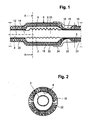
- Fig. 1 and 2 show sections in an axial or radial sectional plane of the pipe with a compensator 2, which is exemplarily as a flexible corrugated pipe or bellows, in particular made of metal, and with the metallic pipe parts 4, 5 in a known manner, in particular by means of welded joints tightly and firmly connected.
- the pipe parts 4, 5 may be components of the not shown, left and right according to drawing subsequent pipeline or connecting pieces of commercially available compensators to make a tight and firm connection with the other components of the pipeline, such as by welding, Flansch- or socket joints.
- the compensator 2, which is referred to below as a tube compensator is surrounded by a further compensator 6, which is referred to below as an insulating compensator.
- the insulating compensator 6 includes a preferably metallic inner jacket 8, which surrounds the tube compensator 2 at a radial distance 10 to form an annular cavity 9.
- the distance 10 is dimensioned according to the requirements and / or conditions of use and / or movements of the pipe part 5 to the longitudinal axis 12 of the pipe part 4.
- the inner jacket 8 is bent radially inwards and, by means of a dash-dotted line connection 14, in particular welded connection, preferably tightly and / or firmly connected to the tube part 4.
- the metallic inner shell 8 is preferably formed in two parts to facilitate the manufacture and / or assembly. At the longitudinal edges of the two parts of the inner shell 8, for example, flanges for connecting said parts are present. It is understood that the inner shell 8, in particular in Dependence of the size or the diameter of the tube compensator 2 can also be constructed of more than two parts.
- the tube part 4, like the inner jacket 8: of the tubular Isoller compensator 6, is surrounded by insulating material or insulating material 18, the inner jacket 8 ensuring the radial support of the insulating material 18 in the area of the tube compensator 2.
- the insulating material 18 is surrounded on the outside by a metallic outer jacket 20, 22.
- the outer shells 20, 21 are integrally formed in a preferred manner, according to the invention, the determination of the insulating compensator 2 takes place directly by means of the connection 14 on the pipe part 4.
- the tube part 5 is likewise surrounded by insulating material or insulating material 19, which radially outside is likewise surrounded by a metallic outer jacket 21.
- the outer casing 21 is guided radially inwards and advantageously connected to the pipe part 5, preferably by welding.
- the insulating material 18, 19 and the insulation as well as the inner shell 8 and the outer shells 20, 21, 22 made of metallic materials and thus a full metal insulation of the tube compensator 2 as well as the entire pipeline, which also from is surrounded by a full metal insulation is created, which is achieved in a particularly advantageous manner, a simple disposal and recycling.
- a protective cap 24 is arranged, which is fixed on the outer casing 21 of the insulation of the pipe part 5.
- the protective cap 24 By means of the protective cap 24, the penetration of foreign substances, in particular flammable diesel fuel, prevented.
- the installation position of the pipe parts 4, 5 with the pipe compensator 2 with respect to the horizontal predetermined such that such foreign matter on the outside of the protective cap 24 can flow without penetrating into the cavity 9 and the terminal portion 23 and / or the insulating material to be able to.
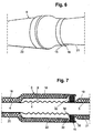
- Fig. 3 shows a perspective view of the insulating device or the insulating compensator 6 with the drawn in the region of the free end 15 of the tube compensator radially inward metallic outer shell 22, which does not directly surrounding the second tube part to form a gap, but its metallic outer jacket 21.
- the protective cap 24 is hereby shown in the assembled state, before this in Direction of the arrow 26 is pushed over the free end 15 of the insulating compensator 6, according to Fig. 2 positioned and fixed on the outer shell 21, in particular by welding and / or spot welding.
- Fig. 4 shows the insulating device similar Fig. 1 , In the upper part of the mounting state is shown, without the insulating material, while in the lower part of the insulating material 18 on the inner shell 8 of the insulating compensator 6 and the tube part 4 and on that of the outer shell 22 is arranged.
- the inner jacket 8 of the insulating compensator 6 is fastened by means of the connection 14 on the pipe part 4, wherein according to the invention a fixed bearing of the insulating compensator 6 is provided on the pipe part 4.
- the gap 16 is present between this and the pipe part 5, so that the insulating compensator 6 is basically independent of relative movements of the pipe parts 4, 5.
- the pipe part 5 in the region of the free end 15 is thus basically a loose bearing available, which allows relative movements of the pipe part 5 with respect to the insulating compensator 6, especially over a much larger circumferential angular range of the crescent-shaped gap 16 is present. Excessive or even unacceptable stresses of the insulating compensator 6 are thus largely avoided even at a fairly large radial and / or angular misalignment.
- Fig. 5 shows an alternative embodiment, according to which both the inner shell 8 and the outer shell 22 of the Isoller compensator 6 are connected in an advantageous manner together with the pipe part 4.
- the dashed line indicates the insulation 18 of the pipe part 4 which immediately adjoins the insulating compensator 6.
- Fig. 6 shows a perspective view of an embodiment in which the radially inwardly bent free end 15 of the insulating compensator 6 engages over the outer casing 21 of the second tube part.
- the basis of Fig. 4 explained annular gap 16 is thus at the free end 15 between the existing there part of the inner shell of the Isoller-compensator 6 and the outer shell 21 is present.
- analogously to Fig. 1 advantageously also be provided here a protective cap.
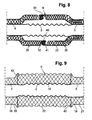
- Fig. 7 an embodiment is shown with an insulating compensator 6, at the free end 15 of the inner shell 8 is bent radially outward and is firmly connected to the outer shell 22, in particular by welding.
- the outer shell 21 of the pipe part 5 surrounded insulation is, however, bent radially inwardly in this area and connected to the outer wall of the pipe part 5, in particular by welding.
- the free end 15 preferably axially overlaps the inwardly bent portion 34 of the outer shell 21 such that between the free end 15 and the radially inwardly bent end portion of the outer shell 21, an annular space 30 is present.
- a flexible sealing element 32 is arranged, which rests sealingly on the one hand radially on the outside of the inner casing 8 and on the other hand radially inwardly on the outer casing 21.
- the end portion 34 of the outer shell 21 is bent radially outward, while in the region of the free end 15, the overlapping end portion 36 of the inner shell 8 is bent radially inwardly, whereby the flexible sealing element 32 is set reliably in the annular space 30.
- the axial distance between the end portions 34, 36 is preferably greater than the axial length of the sealing element 32, so that relative movements of the insulating compensator 6 with respect to the tubular member 5 can be made without further ado and especially without stress of the insulating compensator 6.
- the insulating compensator 6 according to Fig. 8 is formed in two parts, wherein according to the drawing left part 38 is fixedly connected to the pipe part 4 and that analogous to the embodiment of Fig. 1 while the right Kompensatorteil 39 with the second tube part 5 is also firmly connected.
- Analogous to the embodiment according to Fig. 7 are bent at the end portions 34, 36, the ends of the respective inner shell 8 and the associated outer shell 22 and together to define the sealing element 32 in the annular space 30 connected to each other.
- Fig. 9 shows a particular embodiment of the insulating compensator 6 with the formed in particular as a corrugated tube and / or flexible metallic outer shell 22, preferably made of stainless steel. Between the formed in particular as a corrugated tube tube compensator 2 and the corrugated tube or flexible outer casing 22, the insulating material or the insulating material 18 is arranged. It is of particular importance that the insulating material 18 which surrounds the tube compensator 2, as well as this is flexible.
- the tube part 4 and on the tube part 5 substantially radially outwardly extending body 42, 43 arranged and fixed, on which the flexible metallic outer shell 22 in the form of Corrugated tube placed and / or supported and / or secured in a suitable manner.
- the tubular outer shell 22 is thus fixed at its two axial ends indirectly via the body 42 and 43 on the one hand on the one tube part 4 and on the other hand on the two tube part 5 and / or connected thereto.
- the bodies 42, 43 are in particular designed as annular bodies and the fastening of the respective ends of the flexible outer sheath or corrugated tube 22 takes place in particular by welding or by means of pipe clamps or the like.
- the bodies 42, 43 associated ends of the outer shells 20, 21 with the ends of the corrugated tube 22, preferably also with the bodies 42, 43, in particular by welding and / or flanging, connected.
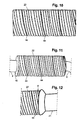
- Fig. 10 shows a side view of the formed as a corrugated tube outer jacket 22 of the insulating compensator.
- the outer shell 22 is formed as a helix of a corrugated sheet-metal strip, wherein the lying in the substantially cylindrical helix longitudinal edges of the original straight sheet metal strip are preferably sealed together and have a corresponding helical connecting portion 44, in particular in the form of a weld.
- the sheet metal strip originally extending in a straight longitudinal direction before forming into a helix is corrugated transversely to the longitudinal direction, suitably rounded troughs and wave heights being present transversely to the longitudinal direction. After winding to a Spiral run the troughs and wave heights at a corresponding angle inclined to the longitudinal axis of the outer shell or after the manufacture of the insulating compensator.
- insulating compensator 6 is shown with the formed as a corrugated tube outer shell 22 after assembly to the tube compensator and on the pipe parts 4, 5.
- the explained and connected to the pipe part 4 body 42 is partially visible.
- Fig. 12 shows partially the insulating compensator 6 with the formed as a corrugated tube outer shell 22, and that after the final installation of the insulation of the second tube part with the surrounding insulation and the outer shell 21.
- the insulating compensator 6 associated end of the metallic outer shell 21 is radial bent outward and / or expanded such that the end of the corrugated tube 22 is overlapped, wherein preferably there the outer jacket 21 is connected to the end of the corrugated tube 22 by welding.
- FIG. 13 to 15 Variants of the annular body 42, 43 are shown for fixing the flexible outer jacket 22 of the insulating compensator 6, wherein the insulating material is omitted for the sake of simplicity.
- the semicircular ring segments 46, 47 are suitably laser or stamped parts, which project in the radial direction from the pipe part 4 to the outside, in Fig. 13 shown below ring body 42 'is made of an L-profile and formed in particular as a stamped or pressed part.
- the ring body 42 ' is also formed at least in two parts, wherein in Fig. 15 the one ring segment 49 in the direction C according to Fig. 13 is shown.
- the ring body 42 'or its respective ring segment 49 has a bend 50 radially outwards such that the outer jacket of the Isoller compensator, which is designed in particular as a corrugated tube, ends with its end in the bend formed by the bend and at the other end the outer shell open space 52 engages.
- the outer jacket of the Isoller compensator which is designed in particular as a corrugated tube
- annular body 43 ' is formed as a U-profile, wherein in preferably in turn two semicircular ring segments are provided. Also in this variant, the coaxial to the pipe part 5 and resting on this inner leg 54 is connected in an advantageous manner with the pipe part 5 by resistance welding.
- the formed as a U-shaped ring body or its semi-circular ring segments are in turn formed as stamped or pressed parts.
- Fig. 16 shows embodiments of the definition and / or attachment of the flexible, in particular designed as a corrugated tube outer sheath 22 of the insulating compensator 6.
- Top left the attachment of the end of the outer sheath 22 is shown on the outer edge of the ring body 42 by means of compression and resistance welding.
- the fastening is carried out by flipping the end of the outer jacket 22 radially inwards and side resistance welding and / or spot welding.
- the annular body 43 engages with its outer edge in a radially inwardly open trough at the end of the outer shell 22.
- a metallic clamp 56 is provided, wherein the ring body 43 is arranged radially inward in the same radial plane.
- the annular clamp 56 engages around and / or engages over the resting on the outer edge of the annular body 43 and / or supported by this end of the outer shell 22 and by means of the radially inwardly open clamp 56 thus the insulating compensator 6 is fixed by pressing on the pipe part 5 ,
- the insulating material 18, 19 surrounds the tube compensator 2 and the tube parts 4, 5 directly, wherein in the lower part of the drawing, the mounting state after the application of the insulating material 18, 19 is shown.
- On the insulating material 18, 19 are two support rings 58 axially spaced, and suitably in the areas above the pipe parts 4, 5, respectively.
- the support rings 58 include radially outwardly directed beads 60 and two laterally of the bead 60 and arranged to the pipe parts 4, 5 substantially coaxial leg 62.
- the metallic outer shells 20 and the other flexible and in particular formed as a corrugated tube or bellows outer shell 22 is connected, in particular by welded joints, as indicated by the dotted lines.
- the compound with the outer surface of the insulating material 18, 19 is produced by means of said compounds, in particular welded joints, whereby in a particularly advantageous manner a secure axial fixing of the support rings 58 is achieved.
- a flange 64 is further connected, which is provided for connection to the pipeline.
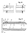
- FIG. 18 illustrated embodiment substantially corresponds to the according Fig. 17
- the two outer shells 20, 21 have overlapping end portions 66, 67, which are preferably arranged substantially in the middle of the longitudinal extent of the tube compensator 2.
- These end portions 66 and 67 are formed as intermeshing waves or beads and form the flexible outer shell 22.
- the thus formed and axially overlapping beads are thus relaxation beads or generally flexible profiling of the outer shell 22.
- an annular gap 68 is present, which in the axial direction corresponding to the contours of the end portions 66, 67 is formed in particular wave-shaped.
- the annular gap 68 due to the intermeshing waves or beads in the manner of a labyrinth seal is effective, in addition, relative movements of the outer shells 20, 21 are basically possible without contact.
- the size of the annular gap 68, both in the axial direction, is predetermined according to the conditions of use and the expected relative movements of the pipe parts 4, 5.
- the radial dimensions of the beads and waves as well as their axial distances are adapted to the requirements.
- the size of the annular gap can go to zero in the context of the invention, wherein the flexibility of the outer shell 22 by the training, in particular material thickness and / or shaping of the profilings or waves or beads, is specified.
Landscapes
- Engineering & Computer Science (AREA)
- General Engineering & Computer Science (AREA)
- Mechanical Engineering (AREA)
- Chemical & Material Sciences (AREA)
- Combustion & Propulsion (AREA)
- Thermal Insulation (AREA)
- Rigid Pipes And Flexible Pipes (AREA)
Abstract
Description
- Die Erfindung bezieht sich auf eine Isoliervorrichtung eines Kompensators einer Rohrleitung gemäß den im Oberbegriff des Patentanspruchs 1 angegebenen Merkmalen.
- Aus der
DE 10 2004 044 172 A1 ist eine derartige Isoliervorrichtung bekannt, welche für eine Abgas-Rohrleitung einer Brennkraftmaschine ausgebildet ist. Die Rohrleitung enthält mehrere Kompensatoren und ist gemeinsam mit den Kompensatoren von einer Isollervorrichtung umgeben. Die Kompensatoren dienen vor allem zum Längenausgleich bei Temperaturänderungen infolge des die Rohrleitung durchströmenden heißen Abgases. Ferner können mittels der Kompensatoren Relativbewegungen und/oder Schwenkungen der übrigen Rohrteile quer und/oder radial zur Längsachse der Rohrleitung ausgeglichen werden. Derartige Bewegungen und/oder Änderungen der Rohrleitung führen zu erheblichen Beanspruchungen der Isoliervorrichtung, insbesondere im Bereich der Kompensatoren, wobei unerwünschte Veränderungen des Isolierverhaltens oder gar Beschädigungen der Isoliervorrichtung insgesamt zu befürchten sind und die Funktionsfähigkeit und Lebensdauer nachteilig beeinflusst werden können. Ein Austausch der Isoliervorrichtung ist mit einem erheblichen Aufwand verbunden. - Hiervon ausgehend liegt der Erfindung die Aufgabe zugrunde, die vorgenannten Nachteile zu vermeiden und mit einem geringen konstruktiven Aufwand die Isoliervorrichtung dahingehend weiterzubilden, dass eine optimierte Dämmwirkung erreicht und für eine lange Lebensdauer sichergestellt werden kann. Die Isoliervorrichtung soll einen geringen Fertigungs- und/oder Montageaufwand erfordern und in einfacher Weise an die jeweiligen Einsatzbedingungen und/oder die betrieblichen Anforderungen anpassbar sein. Die Isoliervorrichtung soll in einfacher Weise herstellbar sein und problemlos handhabbare und/oder miteinander zu verbindende Bestandteile enthalten. Des Weiteren soll die Isoliervorrichtung für ein die Rohrleitung und deren Rohr-Kompensator durchströmendes heißes Medium und/oder für hohe Temperaturen verwendbar sein, und zwar insbesondere für Temperaturen größer als 200°C, zweckmäßig größer als 500°C, bis hin zu 800°C, bevorzugt auch darüber bis 1.000°C. Zudem soll die Isoliervorrichtung in einfacher Weise mit dem Rohr-Kompensator und/oder der Rohrleitung verbindbar sein und/oder eine hohe Stabilität und Dauerfestigkeit aufweisen.
- Die Lösung dieser Aufgabe erfolgt gemäß den im Patentanspruch 1 angegebenen Merkmalen.
- Die erfindungsgemäße Isoliervorrichtung zeichnet sich durch einen einfachen konstruktiven Aufbau aus und besteht in bevorzugter Weise insgesamt aus Metall, und zwar sowohl der Innenmantel als auch der Außenmantel und insbesondere auch das innerhalb des Außenmantels angeordnete Isoliermaterial. Die Isoliervorrichtung oder zumindest ein Teil derselben ist einerseits auf einem der Rohrteile festgelegt und andererseits bezüglich des Rohr-Kompensators bewegbar ausgebildet und/oder angeordnet. Die Isoliervorrichtung ist als ein den Rohr-Kompensator umgebender Isolier-Kompensator erfindungsgemäß ausgebildet und gelangt bevorzugt für ein heißes Medium, wie Abgas, Dampf, pastöses Material oder Flüssigkeit zur Verwendung. Die Isoliervorrichtung ist rohrförmig ausgebildet und umgibt den Rohr-Kompensator und gegebenenfalls zumindest teilweise die axial beabstandet angeordneten Rohrteile, wobei zwischen der Isoliervorrichtung und dem Rohr-Kompensator ein ringförmiger Hohlraum vorhanden ist oder die Isoliervorrichtung unmittelbar auf dem Rohr-Kompensator angeordnet ist. Der erfindungsgemäß vorgesehene Außenmantel ist vorteilhaft dicht, insbesondere flüssigkeitsdicht, ausgebildet, so dass Fremdstoffe nicht in das Isoliermaterial von außen eindringen können. Dies gilt ferner für Verbindungen mit an den Isolier-Kompensator anschließenden Isoliervorrichtungen und/oder mit den Rohrteilen.
- Der Innen- und der Außenmantel bestehen in bevorzugter Weise aus Metallblech oder Metallfolie, insbesondere aus Edelstahl, wobei zumindest die freie äußere Oberfläche des Außenmantels in zweckmäßiger Weise mikrostrukturiert und/oder makrostrukturiert oder gegebenenfalls auch im Wesentlichen glatt ausgeführt sein können. Insbesondere ist der Außenmantel zumindest teilweise, bevorzugt aber insgesamt, flexibel ausgebildet und/oder enthält eine wellenartige Struktur, Profilierung oder Prägungen derart, dass die Isoliervorrichtung ebenso wie der Rohr-Kompensator vor allem Längenänderungen der angeschlossenen Rohrleitung ausgleichen kann. Das Isoliermaterial besteht und/oder enthält vorzugsweise Fasern oder Drähte, insbesondere Edelstahlwolle. Weiterhin kann das Isoliermaterial aus Folien oder Blechen bestehen oder solche enthalten, welche vor allem durch Profilierung, wie Wellen oder Prägungen, zumindest bereichsweise vorgegebene definierte Abstände zueinander aufweisen. Das Isoliermaterial ist ebenso wie der Außen- und der Innenmantel rein metallisch ausgebildet und somit problemlos recycelbar.
- Weiterhin ist von besonderer Bedeutung, dass an gewünschten Positionen und zwar bevorzugt in Verbindungsbereichen oder an Verbindungsstellen von Außenmantel und/oder Isoliermaterial und/oder Innenmantel und ferner vor allem auch mit dem wenigstens einen Rohrteil Verbindungen, insbesondere Schweißverbindungen, vorhanden sind, welche insbesondere durch Punktschweißen und/oder Lichtbogenschweißen hergestellt sind. Die Isoliervorrichtung ist erfindungsgemäß an einem Rohrteil festgelegt und/oder mit diesem verbunden. Bezüglich des anderen im Bereich des anderen Endes des Isolier-Kompensators angeordneten Rohrteils ist der Isolier-Kompensator hingegen im Wesentlichen frei und unabhängig ausgebildet oder zumindest derart flexibel ausgebildet, dass Relativbewegungen der beiden Rohrteile zueinander, vor allem in axialer Richtung, aber auch bei Achs- oder Winkelversatz funktionssicher aufgenommen werden können. Es sei ausdrücklich darauf hingewiesen, dass die beiden axial zueinander beabstandet angeordneten Rohrteile Bestandteile der von einem heißen Medium durchströmbaren Rohrleitung sein können oder Bestandteile des insbesondere handelsüblichen Rohr-Kompensators sein können, wobei die Rohrteile eines solchen Rohr-Kompensators in bekannter Weise, insbesondere durch Schweißverbindungen und/oder Muffenverbindungen und/oder Flanschverbindungen dicht und fest verbunden werden. Weiterhin sind in bevorzugter Weise die Rohrteile und/oder die angeschlossene Rohrleitung von der Isoliervorrichtung oder von weiteren Isoliervorrichtungen umgeben. Die Isoliervorrichtung und insbesondere deren Isoliermaterial ist vor allem zur Wärmedämmung ausgebildet, wobei zusätzlich oder alternativ die Ausbildung zur Schalldämmung vorgesehen sein kann.
- In einer besonderen Ausgestaltung der Erfindung ist der Innenmantel, welcher den Rohr-Kompensator bevorzugt in einem vorgegebenen Abstand umgibt, im Wesentlichen steif zur Abstützung des Isoliermaterials und des umgebenden Außenmantels ausgebildet, welcher insbesondere aus einer dünnen Metallfolie besteht. Der steif ausgebildete Innenmantel ist mit seinem einen Ende auf dem einen Rohrteil befestigt, während das andere dem zweiten Rohrteil zugewandte und/oder zugeordnete Ende des Innenmantels ebenso wie die dortigen Enden des Isoliermaterials und des Außenmantels bezüglich des zweiten Rohrteils frei sind, so dass Relativbewegungen des zweiten Rohrteils bezüglich des erstgenannten Rohrteils im Wesentlichen keine Auswirkungen auf den Isolier-Kompensator haben.
- Gemäß einer anderen besonderen Ausgestaltung der Erfindung ist insbesondere der Außenmantel mittels Befestigungs- und/oder Stützkörpern mit den jeweiligen Enden auf den beiden Rohrteilen festgelegt, wobei vor allem der Außenmantel zumindest teilweise flexibel ausgebildet ist, insbesondere als Wellrohr oder Wellschlauch ausgebildet ist oder vergleichbare Strukturen oder Profilierungen enthält, um Relativbewegungen der axial beabstandet angeordneten Rohrteile ausgleichen zu können.
- Weiterbildungen und besondere Ausgestaltungen der Erfindung sind in den Unteransprüchen und der Beschreibung von Ausführungsbeispielen angegeben. Ausdrücklich sei darauf hingewiesen, dass die erfindungsgemäße Isoliervorrichtung nicht allein für den Einsatz oder die Kombination mit Brennkraftmaschinen bzw. Motoren und Abgas-Rohrleitungen derselben zur Verwendung gelangen können, sondern erfindungsgemäß auch für beliebig ausgebildete Aggregate, wie Turbinen oder Heißgasgebläse oder Wärmetauscher oder Extruder zur Kunststoffverarbeitung, wobei die heißen Medien gasförmig, dampfförmig, pastös oder flüssig sein können.
- Die Erfindung wird nachfolgend anhand der in der Zeichnung dargestellten Ausführungsbeispiele näher erläutert, ohne dass insoweit eine Beschränkung erfolgt. Es zeigen in schematischen Darstellungen:
- Fig. 1
- einen axialen Schnitt durch einen beispielshaft als Wellrohr ausgebildeten Rohr-Kompensator mit der umgebenden Isoliervorrichtung bzw. dem IsolierKompensator,
- Fig. 2
- einen Schnitt entlang Schnittlinie A gemäß
Fig. 1 , - Fig. 3
- eine perspektivische Ansicht der Isoliervorrichtung im Montagezustand, bevor eine Schutzkappe positioniert ist,
- Fig. 4, 5
- einen axialen Schnitt durch ein weiteres Ausführungsbeispiel der Isoliervorrichtung sowie teilweise eine alternative Ausgestaltung,
- Fig. 6
- eine perspektivische Ansicht eines Ausführungsbeispiels ähnlich
Fig. 4 , - Fig. 7
- in einem axialen Schnitt ein Ausführungsbeispiel, bei welchem die dem Kompensator umgebende Isoliervorrichtung bezüglich der übrigen Isolierung mittels eines insbesondere flexiblen Dichtelements abgedichtet ist,
- Fig. 8
- einen axialen Schnitt eines Ausführungsbeispiels mit zwei Kompensatorteilen,
- Fig. 9
- ein besonderes Ausführungsbeispiel der Isoliervorrichtung mit einem flexiblen metallischen Außenmantel,
- Fig. 10
- eine Ansicht des Außenmantels der Isoliervorrichtung gemäß
Fig. 9 , - Fig. 11
- die Isoliervorrichtung gemäß
Fig. 9 im Montagezustand, - Fig. 12
- teilweise eine Ansicht der Isoliervorrichtung des Kompensators und der Rohrleitung,
- Fig. 13
- in einer axialen Schnittebene verschiedene Varianten von Ringkörpern der Isoliervorrichtung,
- Fig. 14, 15
- Ansichten in Blickrichtung B bzw. C der Ringkörper gemäß
Fig. 13 , - Fig. 16
- weitere Ausführungsbeispiele zur Befestigung und/oder Festlegung des als Wellrohr ausgebildeten Außenmantels der Isoliervorrichtung,
- Fig. 17, 18
- zwei weitere Ausführungsbeispiele der Festlegung bzw. Verbindung des metallischen Außenmantels der Isoliervorrichtung.
-
Fig. 1 und 2 zeigen Schnitte in einer axialen bzw. radialen Schnittebene der Rohrleitung mit einem Kompensator 2, welcher beispielshaft als flexibles Wellrohr oder Balg, insbesondere aus Metall, ausgebildet ist und mit den metallischen Rohrteilen 4, 5 in bekannter Weise insbesondere mittels Schweißverbindungen dicht und fest verbunden ist. Die Rohrteile 4, 5 können Bestandteile der nicht weiter dargestellten, links und rechts gemäß Zeichnung anschließenden Rohrleitung sein oder die Anschlußstutzen von handelsüblichen Kompensatoren, um eine dichte und feste Verbindung mit den übrigen Bestandteilen der Rohrleitung herzustellen, wie beispielsweise mittels Schweiß-, Flansch- oder Muffenverbindungen. Der Kompensator 2, welcher nachfolgend als Rohr-Kompensator bezeichnet wird, ist von einem weiteren Kompensator 6 umgeben, welcher nachfolgend als Isolier-Kompensator bezeichnet wird. Der Isolier-Kompensator 6 enthält einen bevorzugt metallischen Innenmantel 8, welcher unter Bildung eines ringförmigen Hohlraums 9 in einem radialen Abstand 10 den Rohr-Kompensator 2 umgibt. Der Abstand 10 ist entsprechend den Anforderungen und/oder Einsatzbedingungen und/oder Bewegungen des Rohrteils 5 zur Längsachse 12 des Rohrteils 4 dimensioniert. An einem dem Rohrteil 4 zugeordneten axialen Ende ist der Innenmantel 8 radial nach innen gebogen und, mittels einer strichpunktiert angedeuteten Verbindung 14, insbesondere Schweißverbindung, mit dem Rohrteil 4 bevorzugt dicht und/oder fest verbunden oder fest gelegt. - Am anderen axialen, und zwar freien Ende 15 ist der Innenmantel 8 gleichfalls nach innen gebogen und er weist dort einen Innendurchmesser derart auf, dass zum anderen oder zweiten Rohrteil 5 ein vorgegebener Ringspalt 16 vorhanden ist, dessen Größe von den Anforderungen, Einsatzbedingungen u.s.w. abhängig vorgegeben ist. Wie aus dem Schnitt A gemäß
Fig. 2 ersichtlich, ist der metallische Innenmantel 8 bevorzugt zweiteilig ausgebildet, um die Fertigung und/oder Montage zu erleichtern. An den Längskanten der beiden Teile des Innenmantels 8 sind beispielsweise Flansche zur Verbindung der genannten Teile vorhanden. Es versteht sich, dass der Innenmantel 8, insbesondere in Abhängigkeit der Größe bzw. des Durchmessers des Rohr-Kompensators 2 auch aus mehr als zwei Teilen aufgebaut sein kann. - Das Rohrteil 4 ist ebenso wie der Innenmantel 8:des rohrförmigen Isoller-Kompensators 6 von Isoliermaterial oder Dämmstoff 18 umgeben, wobei der Innenmantel 8 im Bereich des Rohr-Kompensators 2 die radiale Abstützung des Dämmstoffs 18 sicherstellt. Der Dämmstoff 18 ist außen von einem metallischen Außenmantel 20, 22 umgeben. Die Außenmäntel 20, 21 sind in bevorzugter Weise einteilig ausgebildet, wobei erfindungsgemäß die Festlegung des Isolier-Kompensators 2 direkt mittels der Verbindung 14 auf dem Rohrteil 4 erfolgt. Des Weiteren ist das Rohrteil 5 gleichfalls von Isoliermaterial oder Dämmstoff 19 umgeben, welcher radial außen ebenfalls von einem metallischen Außenmantel 21 umgeben ist. Wie ersichtlich, ist im Bereich des Endes des Innenmantels 8 der Außenmantel 21 radial nach innen geführt und in vorteilhafter Weise mit dem Rohrteil 5, bevorzugt durch Schweißen, verbunden. Es sei ausdrücklich festgehalten, dass der Dämmstoff 18, 19 bzw. die Isolierung ebenso wie der Innenmantel 8 und die Außenmäntel 20, 21, 22 aus metallischen Werkstoffen bestehen und somit eine Vollmetallisolierung des Rohr-Kompensators 2 ebenso wie der gesamten Rohrleitung, welche auch von einer Vollmetallisolierung umgeben ist ,geschaffen ist, wodurch in besonders zweckmäßiger Weise ein einfaches Entsorgen und Recyceln erreicht ist.
- Im gemäß
Fig. 1 rechten Anschlussbereich des Isolier-Kompensators 6 an die Isolierung 19 mit dem Außenmantel 21 des Rohrteils 5 ist bevorzugt eine Schutzkappe 24 angeordnet, welche auf dem Außenmantel 21 der Isolierung des Rohrteils 5 festgelegt ist. Mittels der Schutzkappe 24 wird das Eindringen von Fremdstoffen, insbesondere entzündbarem Dieselkraftstoff, verhindert. Zudem wird vorteilhaft die Einbaulage der Rohrteile 4, 5 mit dem Rohr-Kompensator 2 bezüglich der Horizontalen derart vorgegeben, dass derartige Fremdstoffe über die Außenseite der Schutzkappe 24 abströmen können, ohne in den Hohlraum 9 bzw. den Anschlußbereich 23 und/oder das Isoliermaterial eindringen zu können. -
Fig. 3 zeigt eine perspektivische Ansicht der Isoliervorrichtung bzw. des Isolier-Kompensators 6 mit dem im Bereich des freien Endes 15 des Rohr-Kompensators radial nach innen gezogenen metallischen Außenmantel 22, welcher hierbei nicht unmittelbar das zweite Rohrteil unter Bildung eines Spaltes umgibt, sondern dessen metallischen Außenmantel 21. Die Schutzkappe 24 ist hierbei im Montagezustand dargestellt, bevor diese in Richtung des Pfeils 26 über das freie Ende 15 des Isolier-Kompensators 6 geschoben, gemäßFig. 2 positioniert und auf dem Außenmantel 21, insbesondere durch Schweißen und/oder Punktschweißen, befestigt wird. -
Fig. 4 zeigt die Isoliervorrichtung ähnlichFig. 1 , wobei im oberen Teil der Montagezustand dargestellt ist, ohne das Isoliermaterial, während im unteren Teil das Isoliermaterial 18 auf dem Innenmantel 8 des Isolier-Kompensators 6 und dem Rohrteil 4 sowie auf jenem der Außenmantel 22 angeordnet ist. Der Innenmantel 8 des Isolier-Kompensators 6 ist mittels der Verbindung 14 auf dem Rohrteil 4 befestigt, wobei erfindungsgemäß ein Festlager des Isolier-Kompensators 6 auf dem Rohrteil 4 geschaffen ist. Am anderen, gemäß der Zeichnung rechten freien Ende 15 des Außenmantels 8 ist zwischen diesem und dem Rohrteil 5 der Spalt 16 vorhanden, so dass der Isolier-Kompensator 6 grundsätzlich unabhängig von Relativbewegungen der Rohrteile 4, 5 ist. Sofern die Längsachse 13 des Rohrteils 5 koaxial zur Längsachse 12 des Rohrteils 4 ausgerichtet ist, können Längenänderungen der Rohrteile 4, 5 ohne jede Beeinflussung des Isolier-Kompensators 6 erfolgen. Darüber hinaus können erfindungsgemäß ein Versatz der Längsachsen 12, 13 in radialer Richtung oder um einen Winkel 28 der Rohrteile 4, 5 erfolgen, und zwar in Abhängigkeit der Größe des Ringspaltes 16 bei koaxialer Ausrichtung der Längsachsen 12, 13. Weiterhin führt ein Versatz der Rohrteile 4, 5 derart, dass das Rohrteil 5 an einer Stelle des Umfangs zur Anlage an den nach innen gezogenen Außenmantel 8 gelangt und somit dort der Spalt gegen Null geht, zu keiner wesentlichen Belastung des Isolier-Kompensators 6. In einem solchen Fall gelangt das Rohrteil 5 nur über einen recht kleinen Umfangswinkelbereich zur Anlage an den Isolier-Kompensator 6. Im Bereich des freien Endes 15 ist somit grundsätzlich ein Loselager vorhanden, welches Relativbewegungen des Rohrteils 5 bezüglich dem Isolier-Kompensator 6 ermöglicht, zumal über einen erheblich größeren Umfangswinkelbereich der dann sichelförmige Spalt 16 vorhanden ist. Übermäßige oder gar unzulässige Beanspruchungen des Isolier-Kompensators 6 werden somit selbst bei recht großem Radial- und/oder Winkelversatz weitestgehend vermieden. -
Fig. 5 zeigt eine alternative Ausgestaltung, gemäß welcher sowohl der Innenmantel 8 als auch der Außenmantel 22 des Isoller-Kompensators 6 in vorteilhafter Weise gemeinsam mit dem Rohrteil 4 verbunden sind. Mit gestrichelter Linie ist die an den Isolier-Kompensator 6 unmittelbar anschließende Isolierung 18 des Rohrteils 4 angedeutet. -
Fig. 6 zeigt eine perspektivische Ansicht eines Ausführungsbeispiels, bei welchem das radial nach innen gebogene freie Ende 15 des Isolier-Kompensators 6 den Außenmantel 21 des zweiten Rohrteils übergreift. Der anhand vonFig. 4 erläuterte Ringspalt 16 ist somit am freien Ende 15 zwischen dem dort vorhandenen Teil des Innenmantels des Isoller-Kompensators 6 und dem Außenmantel 21 vorhanden. Im Rahmen der Erfindung kann analog zuFig. 1 in vorteilhafter Weise auch hier eine Schutzkappe vorgesehen sein. - In
Fig. 7 ist ein Ausführungsbeispiel mit einem Isolier-Kompensator 6 dargestellt, an dessen freien Ende 15 der Innenmantel 8 radial nach außen gebogen ist und mit dem Außenmantel 22, insbesondere durch Schweißen, fest verbunden ist. Der Außenmantel 21 der das Rohrteil 5 umgebenen Isolierung ist in diesem Bereich hingegen radial nach innen gebogen und mit der Außenwand des Rohrteils 5, insbesondere durch Schweißen verbunden. Das freie Ende 15 überlappt in bevorzugter Weise axial das nach innen gebogene Teil 34 des Außenmantels 21 derart, dass zwischen dem freien Ende 15 und dem radial nach innen gebogenen Endteil des Außenmantels 21 ein Ringraum 30 vorhanden ist. In diesem Ringraum 30 ist ein flexibles Dichtelement 32 angeordnet, welches einerseits radial außen am Innenmantel 8 und andererseits radial innen am Außenmantel 21 dichtend anliegt. Wie ersichtlich, ist ferner das Endteil 34 des Außenmantels 21 radial nach außen gebogen, während im Bereich des freien Endes 15 das überlappende Endteil 36 des Innenmantels 8 radial nach innen gebogen ist, wodurch das flexible Dichtelement 32 funktionssicher im Ringraum 30 festgelegt ist. Der axiale Abstand zwischen den Endteilen 34, 36 ist in bevorzugter Weise größer als die axiale Länge des Dichtelements 32, so dass Relativbewegungen des Isolier-Kompensators 6 bezüglich des Rohrteils 5 ohne weiteres und vor allem ohne Beanspruchung des Isolier-Kompensators 6 erfolgen können. - Der Isolier-Kompensator 6 gemäß
Fig. 8 ist zweiteilig ausgebildet, wobei ein gemäß Zeichnung linker Teil 38 mit dem Rohrteil 4 fest verbunden ist und zwar analog zum Ausführungsbeispiel derFig. 1 , während der rechte Kompensatorteil 39 mit dem zweiten Rohrteil 5 ebenfalls fest verbunden ist. Die zweckmäßig in der Mitte der Längserstreckung des Rohr-Kompensators 2 vorgesehenen Enden 40, 41 der Kompensatorteile 38, 39 überlappen axial unter Bildung des Ringraums 30 zur Aufnahme des Dichtelements 32. Analog zum Ausführungsbeispiel gemäßFig. 7 sind an den Endteilen 34, 36 die Enden des jeweiligen Innenmantels 8 und des zugeordneten Außenmantels 22 gebogen und miteinander zur Festlegung des Dichtelements 32 im Ringraum 30 miteinander verbunden. -
Fig. 9 zeigt eine besondere Ausgestaltung des Isolier-Kompensators 6 mit dem insbesondere als Wellrohr ausgebildeten und/oder flexiblen metallischen Außenmantel 22, bevorzugt aus Edelstahl. Zwischen dem insbesondere als Wellrohr ausgebildeten Rohr-Kompensator 2 und dem Wellrohr bzw. flexiblen Außenmantel 22 ist das Isoliermaterial bzw. der Dämmstoff 18 angeordnet. Hierbei ist von besonderer Bedeutung, dass das Isoliermaterial 18, welches den Rohr-Kompensator 2 umgibt, ebenso wie dieser flexibel ausgebildet ist. Im Anschluss an das innenliegende Wellrohr des Rohr-Kompensators 2 sind sowohl auf dem Rohrteil 4 als auch auf dem Rohrteil 5 sich im Wesentlichen in radialer Richtung nach außen erstreckende Körper 42, 43 angeordnet und befestigt, auf welchen der flexible metallische Außenmantel 22 in Form des Wellrohres aufgelegt und/oder abgestützt und/oder in geeigneter Weise befestigt ist. Der rohrförmige Außenmantel 22 ist somit an seinen beiden axialen Enden mittelbar über die Körper 42 bzw. 43 einerseits auf dem einen Rohrteil 4 und andererseits auf dem zweien Rohrteil 5 festgelegt und/oder mit diesen verbunden. Die Körper 42, 43 sind insbesondere als Ringkörper ausgebildet und die Befestigung der jeweiligen Enden des flexiblen Außenmantels bzw. Wellrohrs 22 erfolgt insbesondere durch Schweißen oder mittels Rohrschellen oder dergleichen. An den derart ausgebildeten Isolier-Kompensator 6 und insbesondere die genannten Körper 42, 43 schließen in beiden axialen Richtungen über den jeweiligen Rohrteilen 4, 5 und diese umgebend die Isolierungen bzw. das Isoliermaterial 18, 19 mit den metallischen Außenmänteln 20, 21 unmittelbar an. In bevorzugter Weise sind die den Körpern 42, 43 zugeordneten Enden der Außenmäntel 20, 21 mit den Enden des Wellrohrs 22, bevorzugt ferner mit den Körpern 42, 43, insbesondere durch Schweißen und/oder Umbördeln, verbunden. -
Fig. 10 zeigt eine seitliche Ansicht des als Wellrohr ausgebildeten Außenmantels 22 des Isolier-Kompensators. Der Außenmantel 22 ist als Wendel aus einem gewellten Blechstreifen gebildet, wobei die in der im Wesentlichen zylindrischen Wendel aneinander liegenden Längskanten des ursprünglichen geraden Blechstreifens in bevorzugter Weise dicht miteinander verbunden sind und einen entsprechend wendelförmigen Verbindungsbereich 44 aufweisen, insbesondere in Form einer Schweißnaht. Der vor dem Formen zu einer Wendel ursprünglich sich in einer geraden Längsrichtung erstreckende Blechstreifen ist quer zur Längsrichtung gewellt, wobei zweckmäßig abgerundete Wellentäler und Wellenhöhen quer zur Längsrichtung vorhanden sind. Nach dem Aufwickeln zu einer Wendel verlaufen die Wellentäler und Wellenhöhen in einem entsprechenden Winkel geneigt zur Längsachse des Außenmantels bzw. nach der Fertigung des Isolier-Kompensators. - In
Fig. 11 ist der Isolier-Kompensator 6 mit dem als Wellrohr ausgebildeten Außenmantel 22 nach der Montage um den Rohr-Kompensator und auf den Rohrteilen 4, 5 dargestellt. Der erläuterte und mit dem Rohrteil 4 verbundene Körper 42 ist teilweise zu erkennen. -
Fig. 12 zeigt teilweise den Isolier-Kompensator 6 mit dem als Wellrohr ausgebildeten Außenmantel 22, und zwar nach der endgültigen Montage auch der Isolierung des zweiten Rohrteils mit der umgebenden Isolierung und deren Außenmantel 21. Das dem Isolier-Kompensator 6 zugeordnete Ende des metallischen Außenmantels 21 ist radial nach außen gebogen und/oder aufgeweitet derart, dass das Ende des Wellrohrs 22 übergriffen wird, wobei in bevorzugter Weise dort der Außenmantel 21 mit dem Ende des Wellrohrs 22 durch Schweißen verbunden ist. - In
Fig. 13 bis 15 sind Varianten des Ringkörpers 42, 43 zur Festlegung des flexiblen Außenmantels 22 des Isolier-Kompensators 6 dargestellt, wobei das Isoliermaterial der Einfachheit halber weggelassen ist. So besteht der inFig. 13 links oben dargestellte Ringkörper 42 aus zwei sich jeweils über 180° erstreckende Ringsegmenten 46, 47, welche bei Blickrichtung B inFig. 14 dargestellt sind und mittels einer Schweißnaht 48 mit dem Rohrteil 4 verbunden sind. Die halbkreisförmigen Ringsegmente 46, 47 sind in zweckmäßiger Weise Laser- oder Stanzteile, welche in radialer Richtung vom Rohrteil 4 nach außen abstehen, Der inFig. 13 links unten dargestellte Ringkörper 42' ist aus einem L-Profil hergestellt und insbesondere als ein Stanz- oder Pressteil ausgebildet. Der Ringkörper 42' ist ebenfalls zumindest zweiteilig ausgebildet, wobei inFig. 15 das eine Ringsegment 49 in Blickrichtung C gemäßFig. 13 dargestellt ist. Der Ringkörper 42' liegt mit dem zum Rohrteil 4 koaxialen Schenkel auf dem Rohrteil 4 auf und ist insbesondere durch Widerstandsschweißen mit dem Rohrteil 4 verbunden, wie mittels strichpunktierter Linie angedeutet. Gemäß einer mit gestrichelten Linien angedeuteten Weiterbildung weist der Ringkörper 42' bzw. dessen jeweiliges Ringsegment 49 radial außen eine Abwinkelung 50 derart auf, dass der insbesondere als Wellrohr ausgebildete Außenmantel des Isoller-Kompensators mit seinem Ende in den durch die Abwinkelung gebildeten und zum anderen Ende des Außenmantels offenen Freiraum 52 eingreift. Die inFig. 13 rechts unten dargestellte Variante des Ringkörpers 43' ist als ein U-Profil ausgebildet, wobei in bevorzugter Weise wiederum zwei halbkreisförmige Ringsegmente vorgesehen sind. Auch bei dieser Variante ist der zum Rohrteil 5 koaxiale und auf diesem aufliegende innere Schenkel 54 in vorteilhafter Weise mit dem Rohrteil 5 durch Widerstandsschweißen verbunden. Der als U-Profil ausgebildete Ringkörper bzw. dessen halbkreisförmige Ringsegmente sind wiederum als Stanz- oder Preßteile ausgebildet. -
Fig. 16 zeigt Ausführungsbeispiele der Festlegung und/oder Befestigung des flexiblen, insbesondere als Wellrohr ausgebildeten Außenmantels 22 des Isolier-Kompensators 6. Links oben ist die Befestigung des Endes des Außenmantels 22 auf dem Außenrand des Ringkörpers 42 mittels Verpressen und Widerstandsschweißen dargestellt. Gemäß der links unten dargestellten Variante erfolgt die Befestigung durch Umlegen des Endes des Außenmantels 22 radial nach innen und seitliches Widerstandsschweißen und/oder Punktschweißen. Wie bei den links dargestellten Varianten greift bei dem rechts dargestellten Ausführungsbeispiel der Ringkörper 43 mit seinem Außenrand in ein radial nach innen offenes Wellental am Ende des Außenmantels 22 ein. Radial außen über dem Ende des Außenmantels 22 ist eine metallische Schelle 56 vorgesehen, wobei radial innen in der gleichen Radialebene der Ringkörper 43 angeordnet ist. Die ringförmige Schelle 56 umgreift und/oder übergreift das auf dem Außenrand des Ringkörpers 43 aufliegende und/oder von diesem abgestützte Ende des Außenmantels 22 und mittels der radial nach innen offenen Schelle 56 wird durch Verpressen somit der Isolier-Kompensator 6 auf dem Rohrteil 5 befestigt. - Bei dem in
Fig. 17 dargestellten besonderen Ausführungsbeispiel umgibt das Isoliermaterial 18, 19 den Rohr-Kompensator 2 sowie die Rohrteile 4, 5 unmittelbar, wobei im unteren Teil der Zeichnung der Montagezustand nach dem Aufbringen des Isoliermaterials 18, 19 dargestellt ist. Auf dem Isoliermaterial 18, 19 sind zwei Stützringe 58 axial beabstandet, und zwar zweckmäßig in den Bereichen über den Rohrteilen 4, 5, angeordnet. Die Stützringe 58 enthalten radial nach außen gerichtete Sicken 60 und jeweils zwei seitlich der Sicke 60 angeordnete und zu den Rohrteilen 4, 5 im Wesentlichen koaxiale Schenkel 62. Mit den genannten Schenkeln 62 sind zum einen die metallischen Außenmäntel 20 und zum anderen der flexible und insbesondere als Wellrohr oder Balg ausgebildete Außenmantel 22 verbunden, insbesondere durch Schweißverbindungen, wie mittels den strichpunktierten Linien angedeutet. Vorteilhaft ist mittels der genannten Verbindungen, insbesondere Schweißverbindungen, auch die Verbindung mit der Außenfläche des Isoliermaterials 18, 19 hergestellt, wodurch in besonders zweckmäßiger Weise eine sichere axiale Festlegung der Stützringe 58 erreicht ist. Des Weiteren sind die Außenmäntel 20, 21 mit dem zugeordneten Rohrteil 4 bzw. 5 mit dem radial nach innen gebogenen bzw. gezogenen Enden mit dem jeweiligen Rohrteil 4, 5 gemäß den strichpunktierten Linien, insbesondere mittels Schweißverbindungen, verbunden. Mit dem Rohrteil 4 ist ferner ein Flansch 64 verbunden, welcher zum Anschluss an die Rohrleitung vorgesehen ist. - Das in
Fig. 18 dargestellte Ausführungsbeispiel entspricht im Wesentlichen dem gemäßFig. 17 , wobei jedoch die beiden Außenmäntel 20, 21 einander überlappende Endteile 66, 67 aufweisen, welche bevorzugt im Wesentlichen in der Mitte der Längserstreckung des Rohr-Kompensators 2 angeordnet sind. Diese Endteile 66 bzw. 67 sind als ineinander greifende Wellen oder Sicken ausgebildet und bilden den flexiblen Außenmantel 22. Die derart ausgebildeten und axial überlappenden Sicken sind somit Entspannungssicken oder allgemein flexible Profilierungen des Außenmantels 22. In bevorzugter Weise ist zwischen den einander korrespondierend ausgebildeten Wellen bzw. Sicken oder Profilierungen der Endteile 66, 67 ein ringförmiger Spalt 68 vorhanden, welcher in axialer Richtung entsprechend den Konturen der Endteile 66, 67 insbesondere wellenförmig ausgebildet ist. Ferner ist der Ringspalt 68 aufgrund der ineinander greifenden Wellen bzw. Sicken nach Art einer Labyrinthdichtung wirksam, wobei zudem Relativbewegungen der Außenmäntel 20, 21 grundsätzlich berührungsfrei ermöglicht sind. Die Größe des Ringspalts 68, und zwar sowohl in axialer Richtung, ist entsprechend den Einsatzbedingungen und den zu erwartenden Relativbewegungen der Rohrteile 4, 5 vorgegeben. Hierbei werden die radialen Abmessungen der Sicken sowie Wellen ebenso wie deren axiale Abstände den Erfordernissen angepasst. Die Größe des Ringspalts kann im Rahmen der Erfindung gegen Null gehen, wobei die Flexibilität des Außenmantels 22 durch die Ausbildung, insbesondere Materialdicke und/oder Formgebung der Profilierungen oder Wellen oder Sicken, vorgegeben wird. -
- 2
- Rohr-Kompensator
- 4, 5
- Rohrteil
- 6
- Isolier-Kompensator
- 8
- metallischer Innenmantel von 6
- 9
- Hohlraum zwischen 2 und 6
- 10
- Abstand zwischen 2 und 8
- 12, 13
- Längsachse von 4 bzw. 5
- 14
- Schweißverbindung
- 15
- freies axiales Ende von 6
- 16
- Spalt
- 18, 19
- Dämmstoff / Isoliermaterial
- 20, 21
- metallischer Außenmantel von 18, 19
- 22
- metallischer Außenmantel von 6
- 23
- Anschlussbereich
- 24
- Schutzkappe
- 26
- Pfeil
- 28
- Versatz bzw. Winkel
- 30
- Ringraum
- 32
- Dichtelement
- 34
- Endteil von 21
- 36
- Endteil von 8
- 38, 39
- Kompensatorteil
- 40, 41
- Ende von 38 bzw. 39
- 42, 43
- Körper/ Ringkörper
- 44
- wendelförmiger Verbindungsbereich
- 46, 47
- Ringsegment von 42
- 48
- Schweißnaht
- 49
- Ringsegment von 42'
- 50
- Abwinkelung an 49
- 52
- Freiraum
- 54
- innerer Schenkel von 43'
- 56
- Schelle
- 58
- Stützring
- 60
- Sicke in 58
- 62
- Schenkel von 58
- 64
- Flansch
- 66,67
- Endteil von 20, 21
- 68
- Spalt zwischen 66, 67
Claims (12)
- Isoliervorrichtung eines Kompensators (2) einer Rohrleitung, welche von einem insbesondere heißen Medium durchströmbar ist, wobei die Isoliervorrichtung Isoliermaterial (18) enthält und den Kompensator (2) umgibt, welcher Rohrteile (4, 5) enthält oder mit solchen Rohrteilen (4, 5) mit der Rohrleitung verbunden ist,
dadurch gekennzeichnet, dass die Isoliervorrichtung oder zumindest ein Teil derselben einerseits auf dem einen Rohrteil (4) festgelegt ist und andererseits ein bezüglich des zweiten Rohrteils (5) freies Ende (15) aufweist oder zumindest teilweise flexibel ausgebildet ist oder bezüglich des Rohr-Kompensators (2) bewegbar ausgebildet oder angeordnet ist. - Isoliervorrichtung nach Anspruch 1, dadurch gekennzeichnet, dass sie als ein Isolier-Kompensator (6) ausgebildet ist und/oder einen Außenmantel (22) enthält, welcher das Isoliermaterial (18) umgibt, wobei das Isoliermaterial (18) insbesondere auf einem Innenmantel (8) angeordnet ist, welcher einerseits mit dem einen Rohrteil (4) verbunden ist und andererseits im Bereich des freien Endes (15) mit dem Außenmantel (22) verbunden ist, wobei zwischen dem Rohr-Kompensator (2) und dem Innenmantel (8) bevorzugt ein im Wesentlichen ringförmiger Hohlraum (6) vorgesehen ist.
- Isoliervorrichtung nach Anspruch 1 oder 2, dadurch gekennzeichnet, dass sie vollständig aus metallischen Werkstoffen ausgebildet ist und/oder dass im Bereich des freien Endes (15) des Isoller-Kompensators (6) eine Schutzkappe (24) vorgesehen ist, welche auf dem Isoliermaterial (19) des zweiten Rohrteils (5) und/oder auf dem Außenmantel (21) des Isoliermaterials (19) insbesondere festgelegt ist, wobei die Schutzkappe (24) bevorzugt einen Anschlussbereich (23) zwischen dem freien Ende (15) des Isolier-Kompensators (6) und/oder teilweise den axialen Endbereich des Isolier-Kompensators (6) umgreift.
- Isoliervorrichtung nach einem der Ansprüche 1 bis 3, dadurch gekennzeichnet, dass der Innenmantel (8) mit dem einen Rohrteil (4) mittels einer Verbindung (14), insbesondere einer Schweißverbindung, verbunden ist und/oder mit seinem dem Rohrteil (4) zugeordneten Ende radial nach innen gezogen ist und/oder im Bereich über dem Rohr-Kompensator (2) im Wesentlichen koaxial zur Längsachse (12) des Rohrteils (4) ausgebildet ist.
- Isollervorrichtung nach einem der Ansprüche 1 bis 4, dadurch gekennzeichnet, dass sie als Isolier-Kompensator (6) ausgebildet ist und/oder das freie axiale Ende (15) aufweist, welches dem zweiten Rohrteil (5) zugeordnet ist und dieses umgibt, insbesondere unter Bildung eines Ringspalts (16), und/oder dass der Innenmantel (8) und der Außenmantel (22) im Bereich des freien Endes (15) miteinander verbunden sind, insbesondere gemeinsam mit dem dort vorhandenen und bevorzugt zusammen gepressten Isoliermaterial (18).
- Isoliervorrichtung nach einem der Ansprüche 1 bis 5, dadurch gekennzeichnet, dass das freie Ende (15) des Isolier-Kompensators (6) das zweite Rohrteil (5) und/oder dessen Isoliermaterial (19) in axialer Richtung einander überlappend unter Bildung eines Ringraums (30) umgibt und/oder dass in dem Ringraum (30) ein flexibles und/oder elastisches Dichtelement (32) angeordnet ist, wobei der das Isoliermaterial (19) des Rohrteils (5) umgebende Außenmantel (21) im Bereich des freien Endes (15) bevorzugt mit dem Rohrteil (5) verbunden ist, insbesondere gemeinsam mit dem dort vorhandenen und zusammen gepressten Isoliermaterial (19).
- Isoliervorrichtung nach einem der Ansprüche 1 bis 5, dadurch gekennzeichnet, dass der Isolier-Kompensator (6) zwei Kompensatorteile (38, 39) enthält, welche insbesondere im Wesentlichen in der Mitte der Längserstreckung des Isolier-Kompensators (6) einander axial überlappende Enden (40, 41) aufweisen und/oder dass zwischen den Enden (40, 41) ein Ringraum (30) mit einem flexiblen und/oder elastischen Dichtelement (32) angeordnet ist und/oder dass im Bereich der Enden (40, 41) der jeweilige Außenmantel (22) mit dem radial innen liegenden Innenmantel (8) fest verbunden sind, insbesondere gemeinsam mit dem dort vorhandenen und bevorzugt zusammen gepressten Isoliermaterial (19).
- Isoliervorrichtung nach einem der Ansprüche 1 bis 7, dadurch gekennzeichnet, dass der Außenmantel (22) flexibel ausgebildet ist und/oder als ein Wellrohr oder Wellschlauch (22) ausgebildet ist.
- Isoliervorrichtung nach einem der Ansprüche 1 bis 8, dadurch gekennzeichnet, dass wenigstens ein Ende des insbesondere flexibel ausgebildeten Außenmantels (6) mittels eines Körpers (42, 43) festgelegt ist, wobei der Körper (42, 43) bevorzugt als Ringkörper ausgebildet ist, und/oder dass der Körper (42, 43) auf dem zugeordneten Rohrteil (4, 5) festgelegt und/oder mit diesem fest verbunden ist.
- Isoliervorrichtung nach Anspruch 9 , dadurch gekennzeichnet, dass das dem Isolier-Kompensator (6) zugeordnete Ende des Außenmantels (20, 21) des Rohrteils (4, 5) auf dem Körper (42, 43) festgelegt ist und/oder dass mittels des Körpers (42, 43) die jeweiligen Enden der Außenmäntel (20, 21, 22) in radialer Richtung beabstandet zum zugeordneten Rohrteil (4, 5) angeordnet sind.
- Isoliervorrichtung nach einem der Ansprüche 1 bis 10, dadurch gekennzeichnet, dass der flexible Außenmantel (22) mittels zwei axial beabstandet angeordneten Stützringen (58) bezüglich der Rohrteile (4, 5) und/oder des Isoliermaterials (18) festgelegt sind.
- Isollervorrichtung nach Anspruch 11, dadurch gekennzeichnet, dass der Stützring (58) bevorzugt eine radial nach außen gerichtete Sicke (60) sowie Flansche (62) zur Festlegung des Außenmantels (22) sowie der Außenmäntel (20, 21) der Rohrteile (4, 5) aufweist, und/oder dass die Außenmäntel (21) einander axial überlappende Endteile (66, 67) mit ineinander greifenden Sicken oder Wellen oder Profilierungen enthalten.
Applications Claiming Priority (1)
| Application Number | Priority Date | Filing Date | Title |
|---|---|---|---|
| DE202007013741 | 2007-10-01 |
Publications (3)
| Publication Number | Publication Date |
|---|---|
| EP2045451A2 true EP2045451A2 (de) | 2009-04-08 |
| EP2045451A3 EP2045451A3 (de) | 2010-01-27 |
| EP2045451B1 EP2045451B1 (de) | 2012-12-12 |
Family
ID=40158008
Family Applications (1)
| Application Number | Title | Priority Date | Filing Date |
|---|---|---|---|
| EP20080017289 Active EP2045451B1 (de) | 2007-10-01 | 2008-10-01 | Isoliervorrichtung eines Kompensators |
Country Status (2)
| Country | Link |
|---|---|
| EP (1) | EP2045451B1 (de) |
| DE (1) | DE202008013021U1 (de) |
Families Citing this family (7)
| Publication number | Priority date | Publication date | Assignee | Title |
|---|---|---|---|---|
| DE102010021334B4 (de) * | 2010-05-22 | 2013-03-28 | Boa Balg- Und Kompensatoren-Technologie Gmbh | Verfahren zur Herstellung eines Wärmetauschers und Wärmetauscher |
| DE102012200396A1 (de) * | 2012-01-12 | 2013-07-18 | Witzenmann Gmbh | Thermisch isoliertes flexibles Leitungselement |
| DE102012216097B4 (de) * | 2012-09-12 | 2024-11-28 | Witzenmann Gmbh | Entkoppelelement |
| DE102014100296A1 (de) * | 2014-01-13 | 2015-07-16 | Witzenmann Gmbh | Flexibles Leitungselement mit Isolierung |
| DE102017127069B4 (de) * | 2017-11-17 | 2019-08-08 | Dr. Ing. H.C. F. Porsche Aktiengesellschaft | Anordnung eines Abgasrohres und einer Integraldämmung für das Abgasrohr |
| EP4235001B1 (de) * | 2022-02-25 | 2024-10-16 | MAGNA Energy Storage Systems GesmbH | Thermisch isolierte transferleitung mit kuppelelement |
| DE102022125936A1 (de) | 2022-10-07 | 2024-04-18 | Westfalia Metal Hoses Gmbh | Anschlussverbindung zwischen einem Rohrwellschlauch und einem Rohrleitungssystem |
Citations (5)
| Publication number | Priority date | Publication date | Assignee | Title |
|---|---|---|---|---|
| EP0403943A1 (de) | 1989-06-21 | 1990-12-27 | Isolfeu Ag Zurich | Thermische Isolierung für Rohrleitungskompensatoren |
| EP0568835A1 (de) | 1992-05-05 | 1993-11-10 | Witzenmann GmbH Metallschlauch-Fabrik Pforzheim | Kompensationselement für Kunststoffmantelrohrleitungen |
| EP1134478A2 (de) | 2000-02-26 | 2001-09-19 | Thermamax Hochtemperaturdämmung GmbH | Isoliervorrichutng |
| DE102004044172A1 (de) | 2003-09-23 | 2005-04-14 | Ge Jenbacher Gmbh & Co Ohg | Brennkraftmaschine |
| US20060032218A1 (en) | 2002-11-28 | 2006-02-16 | Hutchinson | Decoupling hose for a motor vehicle exhaust system |
Family Cites Families (6)
| Publication number | Priority date | Publication date | Assignee | Title |
|---|---|---|---|---|
| DE3307457A1 (de) * | 1983-03-03 | 1984-09-06 | Hans Skodock Spezialfabrik für nahtlose Metallschläuche GmbH & Co KG, 3000 Hannover | Vorrichtung zum elastischen verbinden zweier mit kunststoff ummantelter rohrleitungen |
| DE8522123U1 (de) * | 1985-08-01 | 1985-09-26 | Pipeline Engineering Gesellschaft für Planung, Bau- und Betriebsüberwachung von Fernleitungen mbH, 4300 Essen | Wärmeisolierter Rohrleitungsabschnitt mit einem Dehnungskompensator zwischen zwei Rohrbögen |
| DE3540231A1 (de) * | 1985-11-13 | 1987-05-14 | Messerschmitt Boelkow Blohm | Kombinierter schall- und schwingungsdaempfer |
| GB9313419D0 (en) * | 1993-06-29 | 1993-08-11 | Wes Technology Inc | Bellows expansion joint |
| DE4414738A1 (de) * | 1994-04-27 | 1995-11-02 | Roth Technik Gmbh | Abgasanlage |
| AT414035B (de) * | 2003-01-24 | 2006-08-15 | Jenbacher Ag | Dämmeinrichtung zum zumindest teilweisen umfassen eines leitungssystems |
-
2008
- 2008-10-01 DE DE202008013021U patent/DE202008013021U1/de not_active Expired - Lifetime
- 2008-10-01 EP EP20080017289 patent/EP2045451B1/de active Active
Patent Citations (5)
| Publication number | Priority date | Publication date | Assignee | Title |
|---|---|---|---|---|
| EP0403943A1 (de) | 1989-06-21 | 1990-12-27 | Isolfeu Ag Zurich | Thermische Isolierung für Rohrleitungskompensatoren |
| EP0568835A1 (de) | 1992-05-05 | 1993-11-10 | Witzenmann GmbH Metallschlauch-Fabrik Pforzheim | Kompensationselement für Kunststoffmantelrohrleitungen |
| EP1134478A2 (de) | 2000-02-26 | 2001-09-19 | Thermamax Hochtemperaturdämmung GmbH | Isoliervorrichutng |
| US20060032218A1 (en) | 2002-11-28 | 2006-02-16 | Hutchinson | Decoupling hose for a motor vehicle exhaust system |
| DE102004044172A1 (de) | 2003-09-23 | 2005-04-14 | Ge Jenbacher Gmbh & Co Ohg | Brennkraftmaschine |
Also Published As
| Publication number | Publication date |
|---|---|
| EP2045451A3 (de) | 2010-01-27 |
| DE202008013021U1 (de) | 2008-12-24 |
| EP2045451B1 (de) | 2012-12-12 |
Similar Documents
| Publication | Publication Date | Title |
|---|---|---|
| EP2045451B1 (de) | Isoliervorrichtung eines Kompensators | |
| DE102009025054B4 (de) | Turbinengehäuse | |
| EP0332853B1 (de) | Leitungsverbindung | |
| DE19722603C1 (de) | Leitungselement mit wenigstens zwei Bälgen und einem diese verbindenden Zwischenrohr | |
| DE69811547T2 (de) | Biegsame Verbindungsvorrichtung | |
| DE19901663A1 (de) | Rohrkupplung | |
| EP1048881B1 (de) | Kältemittelleitung für Klimaanlagen | |
| DE102007016149A1 (de) | Metallschlauchanordnung mit Innen- und Außenschlauch | |
| EP4235001B1 (de) | Thermisch isolierte transferleitung mit kuppelelement | |
| EP3118504B1 (de) | Kompensator, insbesondere für kfz-anwendungen | |
| DE3526481A1 (de) | Verbindung zweier rohrenden durch ein wellrohr | |
| DE2910429A1 (de) | Dehnungsverbindung fuer eine ein unter druck und unter hoher temperatur stehendes fliessfaehiges medium fuehrende rohrleitung | |
| EP2894312B1 (de) | Flexibles Leitungselement mit Isolierung | |
| DE102005047951B4 (de) | Ummantelte Druckleitung | |
| DE3804208C2 (de) | ||
| DE69600074T2 (de) | Flexibles röhrenförmiges Verbindungselement, für die Abgasanlage eines Kraftfahrzeuges | |
| DE102012216097B4 (de) | Entkoppelelement | |
| EP1134478B1 (de) | Isoliervorrichtung | |
| EP1783413B1 (de) | Anordnung zum Verbinden des Endes eines schraubenlinienförmig gewellten Metallrohres mit einem Anschlussstück | |
| EP2851533B1 (de) | Flexibles Leitungselement | |
| DE3445662A1 (de) | Anschlusshuelse an metallringwellschlauch | |
| DE102009049475B4 (de) | Kompensator für Rohrleitungen | |
| DE102019122012A1 (de) | Flexibles Leitungselement aus Metall | |
| DE20022457U1 (de) | Kältemittelleitung für Klimaanlagen | |
| DE3934755C2 (de) | Metallischer Hohlprofil-Dichtring, insbesondere für Kraftfahrzeug-Motoren |
Legal Events
| Date | Code | Title | Description |
|---|---|---|---|
| PUAI | Public reference made under article 153(3) epc to a published international application that has entered the european phase |
Free format text: ORIGINAL CODE: 0009012 |
|
| AK | Designated contracting states |
Kind code of ref document: A2 Designated state(s): AT BE BG CH CY CZ DE DK EE ES FI FR GB GR HR HU IE IS IT LI LT LU LV MC MT NL NO PL PT RO SE SI SK TR |
|
| AX | Request for extension of the european patent |
Extension state: AL BA MK RS |
|
| PUAL | Search report despatched |
Free format text: ORIGINAL CODE: 0009013 |
|
| AK | Designated contracting states |
Kind code of ref document: A3 Designated state(s): AT BE BG CH CY CZ DE DK EE ES FI FR GB GR HR HU IE IS IT LI LT LU LV MC MT NL NO PL PT RO SE SI SK TR |
|
| AX | Request for extension of the european patent |
Extension state: AL BA MK RS |
|
| 17P | Request for examination filed |
Effective date: 20100719 |
|
| 17Q | First examination report despatched |
Effective date: 20100819 |
|
| AKX | Designation fees paid |
Designated state(s): AT BE BG CH CY CZ DE DK EE ES FI FR GB GR HR HU IE IS IT LI LT LU LV MC MT NL NO PL PT RO SE SI SK TR |
|
| REG | Reference to a national code |
Ref country code: DE Ref legal event code: R079 Ref document number: 502008008855 Country of ref document: DE Free format text: PREVIOUS MAIN CLASS: F01N0007100000 Ipc: F16L0059210000 |
|
| RIC1 | Information provided on ipc code assigned before grant |
Ipc: F16L 59/21 20060101AFI20120531BHEP Ipc: F01N 13/18 20100101ALI20120531BHEP Ipc: F01N 13/14 20100101ALI20120531BHEP Ipc: F01N 13/10 20100101ALI20120531BHEP |
|
| GRAP | Despatch of communication of intention to grant a patent |
Free format text: ORIGINAL CODE: EPIDOSNIGR1 |
|
| GRAS | Grant fee paid |
Free format text: ORIGINAL CODE: EPIDOSNIGR3 |
|
| GRAA | (expected) grant |
Free format text: ORIGINAL CODE: 0009210 |
|
| AK | Designated contracting states |
Kind code of ref document: B1 Designated state(s): AT BE BG CH CY CZ DE DK EE ES FI FR GB GR HR HU IE IS IT LI LT LU LV MC MT NL NO PL PT RO SE SI SK TR |
|
| REG | Reference to a national code |
Ref country code: GB Ref legal event code: FG4D Free format text: NOT ENGLISH |
|
| REG | Reference to a national code |
Ref country code: CH Ref legal event code: EP |
|
| REG | Reference to a national code |
Ref country code: AT Ref legal event code: REF Ref document number: 588503 Country of ref document: AT Kind code of ref document: T Effective date: 20121215 |
|
| REG | Reference to a national code |
Ref country code: IE Ref legal event code: FG4D Free format text: LANGUAGE OF EP DOCUMENT: GERMAN |
|
| REG | Reference to a national code |
Ref country code: DE Ref legal event code: R096 Ref document number: 502008008855 Country of ref document: DE Effective date: 20130207 |
|
| PG25 | Lapsed in a contracting state [announced via postgrant information from national office to epo] |
Ref country code: FI Free format text: LAPSE BECAUSE OF FAILURE TO SUBMIT A TRANSLATION OF THE DESCRIPTION OR TO PAY THE FEE WITHIN THE PRESCRIBED TIME-LIMIT Effective date: 20121212 Ref country code: LT Free format text: LAPSE BECAUSE OF FAILURE TO SUBMIT A TRANSLATION OF THE DESCRIPTION OR TO PAY THE FEE WITHIN THE PRESCRIBED TIME-LIMIT Effective date: 20121212 Ref country code: ES Free format text: LAPSE BECAUSE OF FAILURE TO SUBMIT A TRANSLATION OF THE DESCRIPTION OR TO PAY THE FEE WITHIN THE PRESCRIBED TIME-LIMIT Effective date: 20130323 Ref country code: NO Free format text: LAPSE BECAUSE OF FAILURE TO SUBMIT A TRANSLATION OF THE DESCRIPTION OR TO PAY THE FEE WITHIN THE PRESCRIBED TIME-LIMIT Effective date: 20130312 Ref country code: SE Free format text: LAPSE BECAUSE OF FAILURE TO SUBMIT A TRANSLATION OF THE DESCRIPTION OR TO PAY THE FEE WITHIN THE PRESCRIBED TIME-LIMIT Effective date: 20121212 |
|
| REG | Reference to a national code |
Ref country code: NL Ref legal event code: VDEP Effective date: 20121212 |
|
| REG | Reference to a national code |
Ref country code: LT Ref legal event code: MG4D |
|
| PG25 | Lapsed in a contracting state [announced via postgrant information from national office to epo] |
Ref country code: GR Free format text: LAPSE BECAUSE OF FAILURE TO SUBMIT A TRANSLATION OF THE DESCRIPTION OR TO PAY THE FEE WITHIN THE PRESCRIBED TIME-LIMIT Effective date: 20130313 Ref country code: LV Free format text: LAPSE BECAUSE OF FAILURE TO SUBMIT A TRANSLATION OF THE DESCRIPTION OR TO PAY THE FEE WITHIN THE PRESCRIBED TIME-LIMIT Effective date: 20121212 Ref country code: SI Free format text: LAPSE BECAUSE OF FAILURE TO SUBMIT A TRANSLATION OF THE DESCRIPTION OR TO PAY THE FEE WITHIN THE PRESCRIBED TIME-LIMIT Effective date: 20121212 |
|
| PG25 | Lapsed in a contracting state [announced via postgrant information from national office to epo] |
Ref country code: CZ Free format text: LAPSE BECAUSE OF FAILURE TO SUBMIT A TRANSLATION OF THE DESCRIPTION OR TO PAY THE FEE WITHIN THE PRESCRIBED TIME-LIMIT Effective date: 20121212 Ref country code: SK Free format text: LAPSE BECAUSE OF FAILURE TO SUBMIT A TRANSLATION OF THE DESCRIPTION OR TO PAY THE FEE WITHIN THE PRESCRIBED TIME-LIMIT Effective date: 20121212 Ref country code: IS Free format text: LAPSE BECAUSE OF FAILURE TO SUBMIT A TRANSLATION OF THE DESCRIPTION OR TO PAY THE FEE WITHIN THE PRESCRIBED TIME-LIMIT Effective date: 20130412 Ref country code: EE Free format text: LAPSE BECAUSE OF FAILURE TO SUBMIT A TRANSLATION OF THE DESCRIPTION OR TO PAY THE FEE WITHIN THE PRESCRIBED TIME-LIMIT Effective date: 20121212 Ref country code: BG Free format text: LAPSE BECAUSE OF FAILURE TO SUBMIT A TRANSLATION OF THE DESCRIPTION OR TO PAY THE FEE WITHIN THE PRESCRIBED TIME-LIMIT Effective date: 20130312 |
|
| PG25 | Lapsed in a contracting state [announced via postgrant information from national office to epo] |
Ref country code: RO Free format text: LAPSE BECAUSE OF FAILURE TO SUBMIT A TRANSLATION OF THE DESCRIPTION OR TO PAY THE FEE WITHIN THE PRESCRIBED TIME-LIMIT Effective date: 20121212 Ref country code: NL Free format text: LAPSE BECAUSE OF FAILURE TO SUBMIT A TRANSLATION OF THE DESCRIPTION OR TO PAY THE FEE WITHIN THE PRESCRIBED TIME-LIMIT Effective date: 20121212 Ref country code: PT Free format text: LAPSE BECAUSE OF FAILURE TO SUBMIT A TRANSLATION OF THE DESCRIPTION OR TO PAY THE FEE WITHIN THE PRESCRIBED TIME-LIMIT Effective date: 20130412 Ref country code: PL Free format text: LAPSE BECAUSE OF FAILURE TO SUBMIT A TRANSLATION OF THE DESCRIPTION OR TO PAY THE FEE WITHIN THE PRESCRIBED TIME-LIMIT Effective date: 20121212 |
|
| PLBE | No opposition filed within time limit |
Free format text: ORIGINAL CODE: 0009261 |
|
| STAA | Information on the status of an ep patent application or granted ep patent |
Free format text: STATUS: NO OPPOSITION FILED WITHIN TIME LIMIT |
|
| PG25 | Lapsed in a contracting state [announced via postgrant information from national office to epo] |
Ref country code: DK Free format text: LAPSE BECAUSE OF FAILURE TO SUBMIT A TRANSLATION OF THE DESCRIPTION OR TO PAY THE FEE WITHIN THE PRESCRIBED TIME-LIMIT Effective date: 20121212 |
|
| 26N | No opposition filed |
Effective date: 20130913 |
|
| PG25 | Lapsed in a contracting state [announced via postgrant information from national office to epo] |
Ref country code: CY Free format text: LAPSE BECAUSE OF FAILURE TO SUBMIT A TRANSLATION OF THE DESCRIPTION OR TO PAY THE FEE WITHIN THE PRESCRIBED TIME-LIMIT Effective date: 20121212 Ref country code: HR Free format text: LAPSE BECAUSE OF FAILURE TO SUBMIT A TRANSLATION OF THE DESCRIPTION OR TO PAY THE FEE WITHIN THE PRESCRIBED TIME-LIMIT Effective date: 20121212 |
|
| PG25 | Lapsed in a contracting state [announced via postgrant information from national office to epo] |
Ref country code: IT Free format text: LAPSE BECAUSE OF FAILURE TO SUBMIT A TRANSLATION OF THE DESCRIPTION OR TO PAY THE FEE WITHIN THE PRESCRIBED TIME-LIMIT Effective date: 20121212 |
|
| REG | Reference to a national code |
Ref country code: DE Ref legal event code: R097 Ref document number: 502008008855 Country of ref document: DE Effective date: 20130913 |
|
| BERE | Be: lapsed |
Owner name: BDD BETEILIGUNGS G.M.B.H. Effective date: 20131031 |
|
| PG25 | Lapsed in a contracting state [announced via postgrant information from national office to epo] |
Ref country code: MC Free format text: LAPSE BECAUSE OF FAILURE TO SUBMIT A TRANSLATION OF THE DESCRIPTION OR TO PAY THE FEE WITHIN THE PRESCRIBED TIME-LIMIT Effective date: 20121212 |
|
| REG | Reference to a national code |
Ref country code: IE Ref legal event code: MM4A |
|
| PG25 | Lapsed in a contracting state [announced via postgrant information from national office to epo] |
Ref country code: BE Free format text: LAPSE BECAUSE OF NON-PAYMENT OF DUE FEES Effective date: 20131031 |
|
| PG25 | Lapsed in a contracting state [announced via postgrant information from national office to epo] |
Ref country code: IE Free format text: LAPSE BECAUSE OF NON-PAYMENT OF DUE FEES Effective date: 20131001 |
|
| PG25 | Lapsed in a contracting state [announced via postgrant information from national office to epo] |
Ref country code: TR Free format text: LAPSE BECAUSE OF FAILURE TO SUBMIT A TRANSLATION OF THE DESCRIPTION OR TO PAY THE FEE WITHIN THE PRESCRIBED TIME-LIMIT Effective date: 20121212 |
|
| PG25 | Lapsed in a contracting state [announced via postgrant information from national office to epo] |
Ref country code: HU Free format text: LAPSE BECAUSE OF FAILURE TO SUBMIT A TRANSLATION OF THE DESCRIPTION OR TO PAY THE FEE WITHIN THE PRESCRIBED TIME-LIMIT; INVALID AB INITIO Effective date: 20081001 Ref country code: LU Free format text: LAPSE BECAUSE OF NON-PAYMENT OF DUE FEES Effective date: 20131001 |
|
| PG25 | Lapsed in a contracting state [announced via postgrant information from national office to epo] |
Ref country code: MT Free format text: LAPSE BECAUSE OF FAILURE TO SUBMIT A TRANSLATION OF THE DESCRIPTION OR TO PAY THE FEE WITHIN THE PRESCRIBED TIME-LIMIT Effective date: 20121212 |
|
| REG | Reference to a national code |
Ref country code: FR Ref legal event code: PLFP Year of fee payment: 8 |
|
| REG | Reference to a national code |
Ref country code: FR Ref legal event code: PLFP Year of fee payment: 9 |
|
| REG | Reference to a national code |
Ref country code: DE Ref legal event code: R082 Ref document number: 502008008855 Country of ref document: DE Representative=s name: REBLE KLOSE SCHMITT PARTNERSCHAFTSGESELLSCHAFT, DE |
|
| REG | Reference to a national code |
Ref country code: FR Ref legal event code: PLFP Year of fee payment: 10 |
|
| REG | Reference to a national code |
Ref country code: FR Ref legal event code: PLFP Year of fee payment: 11 |
|
| P01 | Opt-out of the competence of the unified patent court (upc) registered |
Effective date: 20230417 |
|
| REG | Reference to a national code |
Ref country code: CH Ref legal event code: U11 Free format text: ST27 STATUS EVENT CODE: U-0-0-U10-U11 (AS PROVIDED BY THE NATIONAL OFFICE) Effective date: 20251101 |
|
| PGFP | Annual fee paid to national office [announced via postgrant information from national office to epo] |
Ref country code: DE Payment date: 20251020 Year of fee payment: 18 |
|
| REG | Reference to a national code |
Ref country code: DE Ref legal event code: R082 Ref document number: 502008008855 Country of ref document: DE Representative=s name: WESCH, ARNO, DR. RER. NAT., DE |
|
| PGFP | Annual fee paid to national office [announced via postgrant information from national office to epo] |
Ref country code: GB Payment date: 20251024 Year of fee payment: 18 |
|
| PGFP | Annual fee paid to national office [announced via postgrant information from national office to epo] |
Ref country code: AT Payment date: 20251021 Year of fee payment: 18 |
|
| PGFP | Annual fee paid to national office [announced via postgrant information from national office to epo] |
Ref country code: FR Payment date: 20251029 Year of fee payment: 18 |
|
| PGFP | Annual fee paid to national office [announced via postgrant information from national office to epo] |
Ref country code: CH Payment date: 20251101 Year of fee payment: 18 |