EP2045406A1 - Toilet cistern with additional water injection and method for emptying - Google Patents
Toilet cistern with additional water injection and method for emptying Download PDFInfo
- Publication number
- EP2045406A1 EP2045406A1 EP07019454A EP07019454A EP2045406A1 EP 2045406 A1 EP2045406 A1 EP 2045406A1 EP 07019454 A EP07019454 A EP 07019454A EP 07019454 A EP07019454 A EP 07019454A EP 2045406 A1 EP2045406 A1 EP 2045406A1
- Authority
- EP
- European Patent Office
- Prior art keywords
- water
- siphon
- unit
- pipe
- water inlet
- Prior art date
- Legal status (The legal status is an assumption and is not a legal conclusion. Google has not performed a legal analysis and makes no representation as to the accuracy of the status listed.)
- Withdrawn
Links
Images

Classifications
-
- E—FIXED CONSTRUCTIONS
- E03—WATER SUPPLY; SEWERAGE
- E03D—WATER-CLOSETS OR URINALS WITH FLUSHING DEVICES; FLUSHING VALVES THEREFOR
- E03D1/00—Water flushing devices with cisterns ; Setting up a range of flushing devices or water-closets; Combinations of several flushing devices
- E03D1/02—High-level flushing systems
- E03D1/06—Cisterns with tube siphons
- E03D1/08—Siphon action initiated by air or water pressure
- E03D1/082—Siphon action initiated by air or water pressure in tube siphons
- E03D1/085—Siphon action initiated by air or water pressure in tube siphons by injection of air or water in the short leg of the siphon
-
- E—FIXED CONSTRUCTIONS
- E03—WATER SUPPLY; SEWERAGE
- E03D—WATER-CLOSETS OR URINALS WITH FLUSHING DEVICES; FLUSHING VALVES THEREFOR
- E03D1/00—Water flushing devices with cisterns ; Setting up a range of flushing devices or water-closets; Combinations of several flushing devices
- E03D1/02—High-level flushing systems
- E03D1/06—Cisterns with tube siphons
- E03D1/08—Siphon action initiated by air or water pressure
- E03D1/082—Siphon action initiated by air or water pressure in tube siphons
- E03D1/087—Siphon action initiated by air or water pressure in tube siphons by pump, valve, or the like, in the short leg of the siphon or a vacuum pump in the long leg of the siphon
-
- E—FIXED CONSTRUCTIONS
- E03—WATER SUPPLY; SEWERAGE
- E03D—WATER-CLOSETS OR URINALS WITH FLUSHING DEVICES; FLUSHING VALVES THEREFOR
- E03D1/00—Water flushing devices with cisterns ; Setting up a range of flushing devices or water-closets; Combinations of several flushing devices
- E03D1/02—High-level flushing systems
- E03D1/14—Cisterns discharging variable quantities of water also cisterns with bell siphons in combination with flushing valves
- E03D1/141—Cisterns discharging variable quantities of water also cisterns with bell siphons in combination with flushing valves in cisterns with tube siphons and with tube siphons in combination with flushing valves
Definitions
- a partition wall is arranged on the water tank bottom, which delimits a small part of the filling space as the suction space for the siphon unit.
- the partition wall extends over part of the height of the filling space and has an overflow with a relation to the riser same or reduced cross section, which is preferably designed as a U-shaped overflow pipe.
- the siphon can advantageously have a vent valve, which is preferably connected to the siphon bend above the overflow edge.
- the vent valve can be manually operated or work automatically. It allows canceling the flush above or below the minimum drain level if a minimum drain is provided. Otherwise, it will allow the water draining to stop at any desired draining level.
- the vent valve can also act as a vent valve in accordance with appropriate design. As an advantage of a manually influenceable ventilation valve is considered that the water jet can be switched off immediately after the initiation of the rinsing process. An automatic valve is particularly advantageous if the emptying process is to be started and stopped solely with the trigger valve.
- the water box 1 is equipped with a trigger valve 12 for triggering the flushing process.
- the trigger valve 12 is disposed in a supply pipe 13 for a water jet, not shown in the drawing to the siphon unit 6; whose outlet opening 14 upstream of the siphon 8 opens into the riser 9 of the siphon unit 6 and is directed in the direction of the siphon 8.
- the float valve 3 is equipped with a float 15.
- the siphon 8 is formed with a vent valve 16 at its highest point.
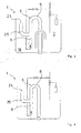
- FIG. 2 shows a simplified embodiment of the water box 1, which allows only a full emptying up to the determined by the water inlet 11 of the siphon unit 6 full emptying level.
- the illustrated water tank 1 differs from that in FIG. 1 shown water tank in that no ventilation valve 16 is provided on the siphon 8.
- the suction chamber 18 of the siphon unit 6 is supplied only via the overflow pipe 19 with rinse water. Since its cross section is reduced relative to the cross section of the riser 9, the water level decreases from there in the suction 18 faster than in the other area of the filling space 2. If there the water level falls below the end 22 'of the overflow pipe 19, the suction chamber 18 is no rinse water more, so that it is quickly emptied until the water inlet 11 of the siphon unit 6 is exposed.
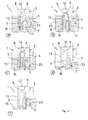
- the supply pipe 13 for the water jet in the region of the pipe bend 30 opens into the downpipe 29 of the first siphon stage 26 of the siphon unit 6.
- the first siphon bend 8 directly and the second siphon bend 28 indirectly, as already described above be vented through the connecting pipe 32.
- a vent valve 16 for stopping the flushing above the full emptying level, in the FIG. 5 not shown, may be provided on the connecting pipe 32.
- the water tank 1 is also designed with the partition wall 17 and the overflow pipe 19. However, the suction space 18 provided thereby is not required in principle, so that the water tank 1 according to the invention is also conceivable without the dividing wall 17 and the overflow pipe 19.
Abstract
Description
Die Erfindung betrifft ein Verfahren zum Entleeren eines Wasserkastens für die Toilettenspülung, mit einem Füllraum für Spülwasser und mit einem mit einem Schwimmerventil ausgestatteten Wasserzulauf zum Befüllen des Füllraums, mit einer Siphoneinheit, die ein Auslaufrohr, mindestens einen Siphonbogen und mindestens ein Steigrohr aufweist, mit einem Wasserablaufstutzen, der mit dem Auslaufrohr an einem Wasserausgang der Siphoneinheit verbunden ist, mit einem Wassereingang für die Siphoneinheit an dem Steigrohr, der im Bereich des Wasserkastenbodens angeordnet ist, und mit einem Auslöseventil zum Auslösen des Spülvorgangs.The invention relates to a method for emptying a water box for toilet flushing, with a filling chamber for rinsing water and equipped with a float valve water inlet for filling the filling chamber, with a siphon unit having an outlet pipe, at least one siphon and at least one riser, with a Water discharge nozzle, which is connected to the outlet pipe at a water outlet of the siphon unit, with a water inlet for the siphon unit on the riser, which is arranged in the region of the water box bottom, and with a trigger valve for triggering the rinsing process.
Die Erfindung betrifft außerdem einen Wasserkasten zur Anwendung des Verfahrens.The invention also relates to a water tank for the application of the method.
Spülvorrichtungen für Toiletten sind in heutiger Zeit im Allgemeinen entweder als sogenannte Druckspülungen oder aber Spülkastenspülungen ausgebildet. Während bei der Druckspülung das Toilettenbecken unmittelbar an die Wasserleitung angeschlossen und kurz vor dem Becken in dieser ein Sperrventil eingebaut ist, benutzt man bei Spülkastenspülungen einen Wasserkasten, der in einer gewissen Höhe über dem Becken an oder in der Wand angebracht ist.Flushing devices for toilets are in the present time generally designed either as so-called pressure flushes or Spülkastenbülungen. While in the flushing the toilet bowl is connected directly to the water pipe and installed just before the pool in this a check valve is, used in Spülkastenbülungen a water tank, which is mounted at a certain height above the pool or in the wall.
Spülkastenspülungen liefern, wenn sie betätigt werden, in der Regel eine vorbestimmte Wassermenge. Sie haben einen größeren Raumbedarf als die Druckspülungen, weil der Wasserkasten untergebracht werden muss. Sie sind dazu ebenfalls recht störanfällig. Häufig muss festgestellt werden, dass nach beendetem Spülvorgang Wasser läuft, weil eine Bodendichtung zum Wasserablaufstutzen defekt ist. Wasserkästen werden hoch- oder tiefhängend angeordnet. Zu der heute gebotenen Wasserersparnis ist häufig eine zweistufige Dosierbarkeit vorgesehen. Als nachteilig wird angesehen, dass der Spüldruck gering ist, da nur die statische Höhe genutzt werden kann. Zudem verringert sich die statische Höhe beim Entleeren des Wasserkastens, so dass der Spüldruck während des Spülvorgangs zunehmend absinkt. Des Weiteren weisen bekannte Spülkastenspülungen oft eine Vielzahl von mechanischen Komponenten auf, die beweglich zusammen wirken und gegenüber Verschmutzungen sehr störanfällig sind.Cistern scavengers, when actuated, typically provide a predetermined amount of water. They have a larger space requirement than the pressure flushes, because the water box must be accommodated. They are also quite susceptible to interference. Often it must be noted that after completion of flushing water is running, because a bottom seal to the water outlet is defective. Water boxes are arranged high or low hanging. To today offered water saving is often a two-stage metering provided. A disadvantage is considered that the flushing pressure is low, since only the static height can be used. In addition, the static height decreases when emptying the water box, so that the rinsing pressure increasingly decreases during the rinsing process. Furthermore, known Spülkastenbülungen often have a variety of mechanical components that act in a mobile manner and are very susceptible to contamination against contamination.
Zur Vermeidung dieser Nachteile sind Wasserkästen mit Einfach- oder Doppelhebersystemen bekannt geworden, die nach dem Siphonprinzip arbeiten. Anders als bei den überwiegend verwendeten Wasserkästen mit einem Bodenventil wird der Spülvorgang bei Wasserkästen dieser Art dadurch eingeleitet, dass eine Entlüftung der in der ersten und/oder zweiten Siphoneinheit nach dem Befüllen des Wasserkastens eingeschlossenen Luft erfolgt. Um danach eine vollständige Entleerung des Wasserkastens sicher zu stellen, muss die Ansaugwirkung der mindestens einen Siphoneinheit während des Spülvorgangs aufrecht erhalten werden. Beispielhaft wird auf die Wasserkästen mit Doppelheberrohrsystem aus der
Der vorliegenden Erfindung liegt die Aufgabe zu Grunde, einen Wasserkasten für die Toilettenspülung vorzuschlagen, der neben einer vollständigen Entleerung auch eine Teilentleerung zur Reduzierung des Wasserverbrauchs zulässt und der eine Mindestentleerung sicherstellt, und bei dem das Auslösen und das Stoppen eines Spülvorgangs jederzeit mit Sicherheit gewährleistet ist.The present invention is based on the object to propose a water tank for toilet flushing, in addition to a complete emptying and a partial emptying to reduce water consumption and ensures a minimum emptying, and in which the triggering and stopping a flushing process is always guaranteed with certainty ,
Diese Aufgabe wird erfindungsgemäß durch ein Verfahren zum Entleeren eines Wasserkastens mit den Merkmalen des Anspruchs 1 und einem Wasserkasten mit den Merkmalen des nebengeordneten Anspruchs 9 gelöst. Weitere vorteilhafte Ausgestaltungen sind den jeweiligen rückbezogenen Unteransprüchen zu entnehmen.This object is achieved by a method for emptying a water tank with the features of
Gemäß dem erfindungsgemäßen Verfahren zum Entleeren eines Wasserkastens wird zum Entleeren des Wasserkastens durch Betätigung des Auslöseventils die Siphoneinheit entlüftet, indem ein Wasserstrahl über ein Zuleitungsrohr in die Siphoneinheit eingeleitet wird, der den Siphonbogen mit Spülwasser auffüllt. Der Wasserstrahl dabei verdrängt die beim Befüllen des Wasserkastens im Siphonbogen eingeschlossene Luft vorzugsweise durch den Wasserausgang der Siphoneinheit. Dabei wird die kinetische Energie des Wasserstrahls ausgenutzt, um das in der Siphoneinheit befindliche Spülwasser anzutreiben und so durch eine Druck- und/oder Sogwirkung die Entlüftung der Siphoneinheit und den Durchfluss des Spülwassers durch die Siphoneinheit zu unterstützen. Das neue Verfahren benötigt kein Entlüftungsventil an dem Siphonbogen der Siphoneinheit, was einerseits den Herstellungsaufwand und damit die Herstellungskosten mindert und andererseits die Störanfälligkeit bei dem Wasserkasten deutlich reduziert. Des Weiteren ist es nach dem Verfahren nicht erforderlich, die sonst übliche Füllhöhe sowie Anordnungshöhe für den Wasserkasten einzuhalten.According to the inventive method for emptying a channel box for emptying the channel box by actuation of the trigger valve, the siphon unit is vented by a water jet is introduced via a feed pipe in the siphon unit, which fills the siphon with rinse water. The water jet thereby displaces the air enclosed in the siphon arc when filling the water box, preferably through the water outlet of the siphon unit. In this case, the kinetic energy of the water jet is utilized to drive the flushing water in the siphon unit and thus to assist by a pressure and / or suction effect the venting of the siphon unit and the flow of the flushing water through the siphon unit. The new method does not require a vent valve on the siphon of the siphon unit, which on the one hand reduces the production cost and thus the manufacturing cost and on the other hand significantly reduces the susceptibility to failure of the water box. Furthermore, it is not necessary according to the method to comply with the usual filling level and arrangement height for the water box.
In der Regel bestimmt allein die Anordnungshöhe des Wasserkastens den Spüldruck einer Toilettenspülung. Oft ist eine niedrige Anordnung bei ausreichendem Spüldruck wünschenswert oder erforderlich. Vorteilhafterweise kann der Wasserkasten mit dem vorgeschlagenen Verfahren beschleunigt entleert werden, in dem in der Siphoneinheit kinetische Energie von dem Wasserstrahl an das Spülwasser übertragen wird. Die kinetische Energie wird solange übertragen wie das Auslöseventil betätigt wird. Damit strömt das Spülwasser mit größerer Geschwindigkeit und mit größerem Druck aus dem Auslaufrohr, als wenn das Spülwasser allein durch den statischen Druck bei der Entleerung beschleunigt wird.As a rule, only the arrangement height of the water box determines the flushing pressure of a toilet flush. Often, a low profile with sufficient purging pressure is desirable or necessary. Advantageously, the water box can be emptied accelerated by the proposed method in which in the siphon unit kinetic energy of the Water jet is transmitted to the rinse water. The kinetic energy is transmitted as long as the trigger valve is actuated. Thus, the rinse water flows with greater speed and pressure from the outlet pipe, as if the rinse water is accelerated solely by the static pressure during emptying.
Das Auslöseventil ist direkt mit der Hauswasserleitung verbunden und wird vorzugsweise von Hand betätigt. Dabei kann die Betätigung jederzeit abgebrochen bzw. wieder aufgenommen werden, so dass der Spülvorgang variabel ist. Dies ist besonders von Vorteil, wenn neben der Vollentleerung des Wasserkastens eine Teilentleerung vorgesehen ist.The trigger valve is connected directly to the domestic water pipe and is preferably operated by hand. In this case, the operation can be aborted or resumed at any time, so that the flushing process is variable. This is particularly advantageous if, in addition to the emptying of the water tank, a partial emptying is provided.
Bekanntermaßen wird der Wasserkasten nach dem Belüften des Siphonbogens so lange entleert, bis der Siphonbogen wieder belüftet wird. Bei einer Vollentleerung bis zu einem Vollentleerungspegel wird der Siphonbogen automatisch über den Wassereingang der Siphoneinheit belüftet, sobald der Pegel in dem Füllraum so weit abgesunken ist, dass der Wassereingang zumindest teilweise freiliegt.As is known, the water tank is emptied after venting the siphon bow until the siphon arc is re-aerated. When completely emptied to a full discharge level, the siphon sheet is automatically vented through the water inlet of the siphon unit as soon as the level in the filling space has dropped sufficiently to at least partially expose the water inlet.
Eine bevorzugte Weiterbildung besteht in einem Verfahren, bei dem der Siphonbogen zum Stoppen des Spülvorgangs bei einem gewünschten Wasserpegel automatisch oder manuell belüftet wird. Vorzugsweise wird zur Teilentleerung des Wasserkastens eine vorzeitige Belüftung des Siphonbogens über ein Belüftungsventil ausgelöst, bevor eine vollständige Entleerung des Füllraums des Wasserkastens bis zu einem Vollentleerungspegel eingetreten ist. Die vorzeitige Belüftung kann manuell zu einem beliebigen Zeitpunkt während des Spülvorgangs vorgenommen werden, so dass die für die Spülung verwendete Wassermenge frei wählbar ist.A preferred development consists in a method in which the siphon arc is automatically or manually ventilated to stop the flushing process at a desired water level. Preferably, to partially deflate the water box, premature aeration of the siphon sheet is initiated via a vent valve before complete emptying of the fill space of the water box has occurred to a full discharge level. The premature ventilation can be done manually at any time during the flushing process, so that the amount of water used for the flushing is freely selectable.
Es ist weiter von Vorteil, eine Mindestentleerung bis zu einem Mindestentleerungspegel bei dem Wasserkasten vorzusehen. Dazu wird der Füllraum über den Wassereingang und einen zusätzlichen, oberhalb des Wassereingangs mit dem Steigrohr verbundenen Wassereintritt entleert, so lange bis der Wassereintritt Luft zieht und damit der Siphonbogen belüftet wird. Das Luftziehen des Wassereintritts kann verhindert werden, indem der Wasserstrahl, der zum Auslösen des Spülvorgangs vorzugsweise über das Steigrohr in den Siphonbogen eingeleitet wird, nach dem Entlüften des Siphonbogens nicht unterbrochen wird. So kann der Füllraum des Wasserkastens über den vorbestimmten Mindestentleerungspegel hinaus bis zu einem gewünschten niedrigeren Wasserpegel oder bis zum Vollentleerungspegel hin entleert werden.It is further advantageous to provide for minimum emptying up to a minimum emptying level at the water box. For this purpose, the filling chamber is emptied through the water inlet and an additional, above the water inlet connected to the riser water inlet, as long as the Water enters air and thus the siphon arc is vented. The air intake of the water inlet can be prevented by the water jet, which is preferably initiated to trigger the rinsing process via the riser in the siphon arc, is not interrupted after venting the siphon. Thus, the filling chamber of the water box can be emptied beyond the predetermined minimum emptying level to a desired lower water level or to the full emptying level.
Bei einer anderen Verfahrensart wird einem Bereich des Füllraums Spülwasser zugeleitet, während der Wasserkasten über einen anderen Bereich entleert wird. Damit wird das für den Spülvorgang bereit zu stellende Spülwasser während des Entleerungsvorgangs des Füllraums ergänzt, was eine kleinere Bauform des Wasserkastens ermöglicht. Außerdem wird die benötigte Zeit, bis ein weiterer Spülvorgang eingeleitet werden kann, deutlich verringert.In another type of process, flushing water is supplied to one area of the filling space, while the water box is emptied over another area. Thus, the flushing water to be provided for the flushing operation is supplemented during the draining operation of the filling space, which allows a smaller construction of the channel box. In addition, the time required until another flushing process can be initiated, significantly reduced.
Nach einer weiteren Verfahrensart wird die aus dem Wasserkasten für den Spülvorgang austretende Wassermenge durch das Auslöseventil und/oder das Belüftungsventil gesteuert. Damit kann der Spülvorgang, so lange der Füllraum des Wasserkastens noch Spülwasser enthält, zu einem beliebigen Zeitpunkt abgebrochen, unterbrochen oder neu ausgelöst werden. So kann die austretende Spülwassermenge an den tatsächlichen Bedarf angepasst werden.According to another method, the amount of water exiting the water box for the flushing process is controlled by the triggering valve and / or the venting valve. Thus, the rinsing process, as long as the filling chamber of the water box still contains rinse water, stopped at any time, interrupted or re-triggered. Thus, the emerging flushing water can be adjusted to the actual needs.
Eine bevorzugte Weiterbildung des Verfahrens besteht in einer Verfahrensart, bei der der Zufluss von Spülwasser zu dem Wassereingang der Siphoneinheit bei einem reduzierten Wasserpegel im Füllraum verringert wird. Dies wird durch geeignete Maßnahmen bei der Gestaltung des Wasserkastens erreicht, wobei der Zufluss zu dem Wassereingang kontinuierlich oder sprunghaft abnehmen kann. Damit wird erreicht, dass das Belüften des Siphonbogens über den Wassereingang der Siphoneinheit ohne große Turbulenzen erfolgt und der Wasserstrom durch die Siphoneinheit bei vollständiger Entleerung schnell und bei einem definierten Vollentleerungspegel zuverlässig abreißt.A preferred embodiment of the method consists in a method in which the inflow of rinse water is reduced to the water inlet of the siphon unit at a reduced water level in the filling space. This is achieved by appropriate measures in the design of the water box, the inflow to the water inlet can decrease continuously or suddenly. This ensures that the aeration of the siphon arc over the water inlet of the siphon unit without great turbulence and the water flow through the siphon unit with complete emptying quickly and reliably breaks off at a defined full emptying level.
Der erfindungsgemäße Wasserkasten für die Toilettenspülung, mit einem Füllraum für Spülwasser und einem mit einem Schwimmerventil ausgestatteten Wasserzulauf zum Befüllen des Füllraums, weist mindestens eine Siphoneinheit auf, die mindestens aus einem Auslaufrohr, mindestens einem Siphonbogen und mindestens einem Steigrohr besteht. Außerdem weist der Wasserkasten einen Wasserablaufstutzen auf, der mit dem Wasserausgang des Auslaufrohrs verbunden ist, wobei ein Wassereingang für die Siphoneinheit im Bereich des Wasserkastenbodens angeordnet ist. An dem Wasserkasten ist ein Auslöseventil zum Auslösen des Spülvorgangs vorgesehen. Es wird insbesondere ein Wasserkasten vorgeschlagen, bei dem vorteilhafterweise das Auslöseventil in einem Zuleitungsrohr für einen Wasserstrahl zur Siphoneinheit angeordnet ist, dessen Austrittsöffnung vor oder nach dem Siphonbogen in die Siphoneinheit mündet. Die Austrittsöffnung weist bevorzugt stromabwärts. Zum Entleeren des Wasserkastens wird durch Betätigung des Auslöseventils die Siphoneinheit, insbesondere der Siphonbogen entlüftet, indem der aus dem Zuleitungsrohr austretende Wasserstrahl in den Siphonbogen geleitet wird. Der Wasserstrahl bringt Wasser mit hoher kinetischer Energie in den Siphonbogen ein und verdrängt damit die im Siphonbogen eingeschlossene Luft. Die Luft kann dabei über den Wassereingang und/oder den Wasserausgang der Siphoneinheit entweichen, wobei der Wasserausgang bevorzugt wird.The water box for toilet flushing according to the invention, with a filling space for rinsing water and a water inlet equipped with a float valve for filling the filling space, has at least one siphon unit, which consists of at least one outlet pipe, at least one siphon bow and at least one riser. In addition, the water box on a water outlet nozzle, which is connected to the water outlet of the outlet pipe, wherein a water inlet for the siphon unit is arranged in the region of the water box bottom. At the water box, a trigger valve for triggering the flushing operation is provided. In particular, a water box is proposed, in which advantageously the release valve is arranged in a supply pipe for a water jet to the siphon unit, whose outlet opening opens into the siphon unit before or after the siphon arc. The outlet opening preferably has downstream. To empty the water tank, the siphon unit, in particular the siphon arc, is vented by actuating the trigger valve by passing the water jet emerging from the supply pipe into the siphon arc. The jet of water introduces high-kinetic energy into the siphon arc, displacing the air trapped in the siphon arc. The air can escape via the water inlet and / or the water outlet of the siphon unit, wherein the water outlet is preferred.
Sobald die Siphoneinheit entlüftet ist, beginnt der Entleerungsvorgang des Füllraumes. Es hat sich als zweckmäßig erwiesen, den Siphonbogen so hoch wie möglich in dem Wasserkasten anzuordnen, um einen möglichst hohen statischen Druck für den Spülvorgang zu erzeugen. Während der Dauer des Spülvorgangs bleibt, bei gleichzeitigem Antrieb durch den Wasserstrahl, der statische, durch die Einbauhöhe bestimmte geodätische Druck, unverändert erhalten. Zusätzlich kann die Spülenergie über die geodätische Fallhöhe hinaus vergrößert werden, in dem der Wasserstrahl energetisch verstärkt wird. Dies zusammen ermöglicht den erfindungsgemäßen Wasserkasten tief zu hängen. Der Entleerungsvorgang dauert so lange an, bis der Siphonbogen belüftet wird. Dies kann beim Erreichen des Vollentleerungspegels geschehen, indem Luft durch den Wassereingang des Steigrohres in den Siphonbogen einströmt, oder vorzeitig, indem für eine Teilentleerung eine Luftzufuhr beim Erreichen eines Teilentleerungspegels über ein Belüftungseinrichtung stattfindet.As soon as the siphon unit has been vented, the emptying process of the filling chamber begins. It has proven to be expedient to arrange the siphon bow as high as possible in the water box in order to generate the highest possible static pressure for the flushing process. During the duration of the rinsing process, the static, determined by the installation height geodetic pressure remains unchanged, while driving through the water jet, unchanged. In addition, the rinsing energy can be increased beyond the geodetic drop height, in which the water jet is energetically amplified. This together allows the water tank according to the invention to hang low. The emptying process continues until the siphon arc is vented. This can be achieved by reaching the full discharge level by passing air through the water inlet of the Rising pipe flows into the siphon arc, or prematurely, by taking place for a partial emptying an air supply when reaching a Teilentleerungspegels via a ventilation device.
Der Siphonbogen des Wasserkastens weist eine Überlaufkante auf, die vorzugsweise mittig zwischen einem Übergang des Siphonbogens zum Steig- und zum Auslaufrohr angeordnet ist. Der Siphonbogen sowie die Überlaufkante kann dabei eckig oder abgerundet ausgeführt sein. Nach dem Befüllen des Wasserkastens steht das Spülwasser in dem Steig- und dem Auslaufrohr unterhalb der Überlaufkante, so dass ein Luftvolumen in dem Siphonbogen eingeschlossen ist. Durch den Wasserstrahl, der beim Betätigen des Auslöseventils ausgelöst wird, steigt der Wasserspiegel in der Siphoneinheit fortlaufend, wobei das Luftvolumen durch den Wasserdruck in Verbindung mit der kinetischen Energie des Wasserstrahls bis zum vollständigen Entweichen aus dem Siphonbogen verdrängt wird.The siphon of the water box has an overflow edge, which is preferably arranged centrally between a transition of the siphon bow to the riser and the outlet pipe. The siphon bend and the overflow edge can be made square or rounded. After filling the water box, the rinse water is in the riser and the spout below the overflow edge, so that an air volume is trapped in the siphon arc. The water jet, which is triggered when the trigger valve is actuated, causes the water level in the siphon unit to rise continuously, the air volume being displaced from the siphon arc by the water pressure in conjunction with the kinetic energy of the water jet until complete escape.
Nach einer vorteilhaften Ausführungsart des Wasserkastens ist an dem Wasserkastenboden eine Trennwand angeordnet, die von dem Füllraum einen kleinen Teil als Ansaugraum für die Siphoneinheit abgrenzt. Die Trennwand erstreckt sich dabei über einen Teil der Höhe des Füllraumes und weist einen Überlauf mit einem gegenüber dem Steigrohr gleichen oder reduziertem Querschnitt auf, der vorzugsweise als U-förmiges Überlaufrohr ausgebildet ist.According to an advantageous embodiment of the water box, a partition wall is arranged on the water tank bottom, which delimits a small part of the filling space as the suction space for the siphon unit. The partition wall extends over part of the height of the filling space and has an overflow with a relation to the riser same or reduced cross section, which is preferably designed as a U-shaped overflow pipe.
Beim Entleeren des Wasserkastens beim Spülvorgang sinkt der Wasserpegel im Wasserkasten kontinuierlich. Davon sind der Füllraum sowie der abgegrenzte Ansaugraum gleichermaßen betroffen. Nach dem Erreichen der Oberkante der Trennwand ist der Ansaugraum nur noch über den Überlauf mit dem restlichen Teil des Füllraums verbunden. Ab diesem Zeitpunkt fließt das Wasser aus dem Füllraum dem Ansaugraum verlangsamt und nur noch in geringer Menge zu. Damit beruhigt sich der Wasserpegel in dem Ansaugraum, so dass die Sogwirkung der Siphoneinheit bei Lufteintritt durch den Wassereingang des Steigrohres definiert abreißen kann.When emptying the water box during the flushing process, the water level in the water tank drops continuously. Of these, the filling chamber and the delimited suction chamber are equally affected. After reaching the upper edge of the partition of the suction chamber is connected only via the overflow with the remaining part of the filling space. From this point on, the water from the filling room slows down the suction chamber and only in small quantities. This calms the water level in the suction chamber, so that the suction effect of the siphon unit can break off when the air enters through the water inlet of the riser pipe.
Vorzugsweise weisen die Enden des Überlaufrohrs einen unterschiedlichen Abstand zum Wasserkastenboden auf, wobei das in den Ansaugraum hinein ragende Ende vorzugsweise gegenüber dem Wassereingang der Siphoneinheit einen gleichen oder größeren Abstand zu dem Wasserkastenboden aufweist. Der dem Ansaugraum nicht zugeordnete Schenkel des Überlaufrohrs ist gegenüber dem anderen Schenkel kürzer, so dass der Wasserzulauf zum Ansaugraum vollständig unterbrochen ist, bevor der Wasserpegel in dem Ansaugraum bis zu dem Wassereingang abgesunken ist. Damit entstehen im Ansaugraum kurz vor dem Erreichen des Vollentleerungspegels keinerlei Turbulenzen mehr, so dass der Abriss der Strömung durch die Siphoneinheit problemlos erfolgt.Preferably, the ends of the overflow pipe at a different distance to the water tank bottom, wherein the protruding into the suction end preferably has a same or greater distance from the water inlet bottom of the siphon with respect to the water inlet of the siphon. The suction chamber unassigned leg of the overflow pipe is shorter compared to the other leg, so that the water inlet to the suction is completely interrupted before the water level in the suction chamber has dropped to the water inlet. This creates no more turbulence in the suction just before reaching the full emptying level, so that the demolition of the flow through the siphon unit is done easily.
In einer vorteilhaften Ausführungsform der Erfindung weist das Steigrohr der Siphoneinheit oberhalb des Wassereingangs einen Zulaufstutzen zum Siphon-bogen mit einem Wassereintritt auf. Der Zulaufstutzen kann sich beispielsweise gerade oder nach oben bzw. unten abgewinkelt von dem Steigrohr weg erstrecken. Dabei ist die Position und die Ausrichtung des Wassereintritt von der Ausführung des Zulaufstutzens abhängig. Der Wassereintritt ist zweckmäßigerweise unterhalb der Überlaufkante des Siphonbogens angeordnet und weist vorzugsweise von dem Wasserkastenboden weg. Zu Beginn der Entleerung des Wasserkastens wird das Spülwasser von der Siphoneinheit gleichzeitig über den Wassereintritt des Zulaufstutzens und über den Wassereingang des Steigrohres aus dem Füllraum abgesaugt. Dies geschieht bis der Wasserpegel im Füllraum das Niveau des Wassereintritts erreicht hat. Von da ab fließt kein Spülwasser mehr in den Zulaufstutzen, so dass kurz darauf das Steigrohr und somit der Siphonbogen durch Lufteintritt durch den Zulaufstutzen belüftet wird.In an advantageous embodiment of the invention, the riser of the siphon above the water inlet on an inlet nozzle to the siphon bow with a water inlet. The inlet nozzle may, for example, extend straight away or upwards or downwards away from the riser pipe. The position and orientation of the water inlet is dependent on the design of the inlet nozzle. The water inlet is expediently arranged below the overflow edge of the siphon arc and preferably points away from the water box bottom. At the beginning of the emptying of the water box, the rinse water is sucked from the siphon unit at the same time on the water inlet of the inlet nozzle and the water inlet of the riser pipe from the filling space. This happens until the water level in the filling room has reached the level of water entry. From there on, no rinse water flows into the inlet nozzle, so that shortly thereafter the riser pipe and thus the siphon arc is vented through air inlet through the inlet nozzle.
Eine Belüftung des Siphonbogens ist jedoch trotzdem ausgeschlossen, so lange der Wasserstrahl in das Steigrohr eingeleitet wird. Der Wasserstrahl bewirkt eine "Abdichtung" zu dem Zulaufstutzen hin. So ist es möglich, den Wasserkasten alternativ teilweise oder vollständig zu entleeren. Wird der Wasserstrahl gleich zu Beginn nach dem Entlüften der Siphoneinheit abgeschaltet, so wird der Füllraum nur bis zu dem von dem Wassereintritt bestimmten Teilentleerungspegel geleert.However, a ventilation of the siphon arc is still excluded, as long as the water jet is introduced into the riser. The water jet causes a "seal" to the inlet nozzle. Thus, it is possible to empty the water tank alternatively partially or completely. If the water jet is switched off immediately after venting the siphon unit, the filling space is emptied only up to the partial discharge level determined by the water inlet.
Daher ergibt sich die Höhe des Mindestentleerungspegels durch den Abstand des Wassereintritts von dem Wasserkastenboden. Vor dem Erreichen des Mindestentleerungspegels kann der Spülvorgang nicht abgebrochen werden. Nach dem Unterschreiten des Mindestentleerungspegels bei eingeschaltetem Wasserstrahl kann der Spülvorgang jederzeit beendet werden, indem der Wasserstrahl abgeschaltet wird.Therefore, the height of the minimum emptying level results from the distance of the water inlet from the water box bottom. Before reaching the minimum emptying level, the flushing process can not be aborted. After falling below the minimum emptying level when the water jet is switched on, the flushing process can be stopped at any time by switching off the water jet.
Um den Entleerungsvorgang des Wasserkastens bei einem beliebigen Wasserpegel abbrechen zu können, kann der Siphonbogen vorteilhafterweise ein Belüftungsventil aufweisen, das vorzugsweise oberhalb der Überlaufkante mit dem Siphonbogen verbunden ist. Das Belüftungsventil kann manuell betätigbar sein oder automatisch arbeiten. Es ermöglicht das Abbrechen des Spülvorgangs oberhalb oder unterhalb des Mindestentleerungspegels, falls eine Mindestentleerung vorgesehen ist. Ansonsten ermöglicht es das Stoppen der Wasserkastenentleerung bei jedem gewünschten Teilentleerungspegel. Das Belüftungsventil kann bei entsprechend geeigneter Ausführung auch als Entlüftungsventil wirken. Als Vorteil eines von Hand beeinflussbaren Belüftungsventils wird angesehen, dass der Wasserstrahl sofort nach dem Auslösen des Spülvorgangs abgeschaltet werden kann. Ein automatisches Ventil ist besonders dann vorteilhaft, wenn das Entleerungsvorgang allein mit dem Auslöseventil gestartet und gestoppt werden soll.In order to be able to stop the emptying process of the water box at any water level, the siphon can advantageously have a vent valve, which is preferably connected to the siphon bend above the overflow edge. The vent valve can be manually operated or work automatically. It allows canceling the flush above or below the minimum drain level if a minimum drain is provided. Otherwise, it will allow the water draining to stop at any desired draining level. The vent valve can also act as a vent valve in accordance with appropriate design. As an advantage of a manually influenceable ventilation valve is considered that the water jet can be switched off immediately after the initiation of the rinsing process. An automatic valve is particularly advantageous if the emptying process is to be started and stopped solely with the trigger valve.
Ein automatisches Be-/Entlüftungsventil kann beispielsweise als Schwimmerventil mit einem Tischtennisball als Schwimmer ausgebildet sein und eine Prallplatte für etwaige Undichtigkeiten des Ventils aufweisen. Solange das Auslöseventil betätigt ist, wird das Steigrohr und der daran anschließende Siphonbogen von dem freigegebenen Wasserstrahl mit einem Wasserüberdruck beaufschlagt. Durch den Überdruck schwimmt der Tischtennisball des vorzugsweise am Hochpunkt des Siphonbogens angeordneten Ventils auf, das damit geschlossen wird. Der Siphonbogen kann nunmehr vollständig entlüftet werden. Damit beginnt der Entleerungsvorgang des Wasserkastens, der solange anhält, wie das Auslöseventil geöffnet ist. Nach dem Schließen des Auslöseventils wird kein Wasserstrahl mehr in die Siphoneinheit eingeleitet. Der Überdruck in dem Siphonbogen baut sich damit ab, so dass der Tischtennisball absinkt, wodurch das Schwimmerventil automatisch öffnet und der Siphonbogen belüftet wird.An automatic ventilation valve can be designed, for example, as a float valve with a table tennis ball as a float and have a baffle plate for any leaks in the valve. As long as the trigger valve is actuated, the riser and the subsequent Siphonbogen is acted upon by the released water jet with a water pressure. Due to the overpressure of the table tennis ball floats preferably arranged at the high point of the siphon bend valve, which is closed with it. The siphon bow can now be completely vented. This begins the emptying process of the water box, which lasts as long as the release valve is open. After closing the trigger valve is no Water jet more introduced into the siphon unit. The overpressure in the siphon arc breaks down, causing the table tennis ball to drop, automatically opening the float valve and venting the siphon arc.
Nach einer anderen bevorzugten Ausführungsart des erfindungsgemäßen Wasserkastens ist die Siphoneinheit zweistufig ausgebildet. Sie weist eine den Wassereingang aufweisende erste Siphonstufe und eine anschließende zweite Siphonstufe auf, wobei die erste, den Wassereingang aufweisende Siphonstufe, gegenüber der zweiten, den Wasserausgang aufweisenden Siphonstufe, eine höhere Überlaufkante aufweist.According to another preferred embodiment of the water box according to the invention, the siphon unit is formed in two stages. It has a water inlet having the first siphon and a subsequent second siphon, wherein the first, the water inlet having siphon, with respect to the second, the water outlet having siphon, a higher overflow edge.
Die Siphoneinheit weist demzufolge einen ersten und einen zweiten Siphonbogen auf, wobei ein Fallrohr der ersten Siphoneinheit mit einem Steigrohr der zweiten Siphoneinheit über einen unteren Rohrbogen miteinander verbunden ist. Dabei ist der erste Siphonbogen, der der ersten Siphoneinheit zugeordnet ist, über ein Verbindungsrohr mit dem Steigrohr der zweiten Siphoneinheit unterhalb des zweiten Siphonbogens verbunden. Außerdem kann an dem Verbindungsrohr ein Belüftungsventil vorgesehen sein, mit dem die beiden Siphohbögen gleichzeitig belüftet werden können. Zur Entlüftung beim Auslösen des Spülvorgangs dient wie bei der einstufigen Ausführung der Siphoneinheit ein Auslöseventil für einen Wasserstrahl, das in einem Zuleitungsrohr angeordnet ist, welches vorzugsweise in das Fallrohr der ersten Siphoneinheit stromabwärts des ersten Siphonbogens mündet.The siphon unit accordingly has a first and a second siphon arc, wherein a downpipe of the first siphon unit is connected to a riser pipe of the second siphon unit via a lower pipe bend. In this case, the first siphon arc, which is assigned to the first siphon unit, is connected via a connecting pipe to the riser pipe of the second siphon unit below the second siphon bow. In addition, a ventilation valve may be provided on the connecting tube with which the two Siphohbögen can be ventilated simultaneously. For venting when triggering the flushing serves as in the single-stage design of the siphon a trigger valve for a water jet, which is arranged in a supply pipe, which preferably opens into the downpipe of the first siphon unit downstream of the first siphon.
In einer Ausführungsart ist insbesondere vorgesehen, dass das Zuleitungsrohr an seiner Austrittsöffnung eine Düse aufweist. Die Düse bewirkt eine Erhöhung des Wasserdruckes des austretenden Wasserstrahls und damit eine Erhöhung seiner kinetischen Energie. Mit der erhöhten kinetischen Energie kann beispielsweise die im Steigrohr, im Fallrohr oder im Auslaufrohr stehende Wassersäule in Bewegung versetzt werden, um durch Druck oder Sog die Entlüftung und falls gewünscht den Durchfluss durch die Siphoneinheit zu beschleunigen. Die Austrittsöffnung mit der Düse kann in das Steigrohr und/oder Fallrohr und/oder Auslaufrohr der Siphoneinheit hinein ragen. Dabei ist die Düse stromabwärts zu richten, um ein beschleunigtes Entleeren zu ermöglichen. Ansonsten kann die Düse auch stromaufwärts gerichtet sein.In one embodiment it is provided in particular that the supply pipe has a nozzle at its outlet opening. The nozzle causes an increase in the water pressure of the exiting water jet and thus an increase in its kinetic energy. With the increased kinetic energy, for example, the standing in the riser, the downpipe or the outlet pipe water column can be set in motion to accelerate by pressure or suction the vent and, if desired, the flow through the siphon unit. The outlet opening with the nozzle can protrude into the riser and / or downpipe and / or outlet pipe of the siphon unit. The nozzle is downstream to to accelerate emptying. Otherwise, the nozzle can also be directed upstream.
Nachfolgend wird die Erfindung anhand von Ausführungsbeispielen näher erläutert. Weitere Merkmale der Erfindung ergeben sich aus den beigefügten Zeichnungen und der Beschreibung der Ausgangsbeispiele in Verbindung mit den Ansprüchen. Die einzelnen Merkmale der Erfindung können für sich allein oder zu mehreren bei verschiedenen Ausführungsformen der Erfindung realisiert sein. In einer schematischen Darstellung zeigen:
Figur 1- einen ersten erfindungsgemäßen Wasserkasten mit einstufiger Siphoneinheit und mit Stoppfunktion;
Figur 2- einen zweiten erfindungsgemäßen Wasserkasten mit einstufiger Siphoneinheit ohne Stoppfunktion;
Figur 3- einen dritten erfindungsgemäßen Wasserkasten mit einstufiger Siphoneinheit und mit Mindestentnahme;
- Figur 4
- einen vierten erfindungsgemäßen Wasserkasten mit einstufiger Siphoneinheit und Mindestentnahme,
Figur 5- einen fünften erfindungsgemäßen Wasserkasten mit zweistufiger Siphoneinheit ohne Stoppfunktion; und
Figur 6- den Ablauf des Spülvorgangs des Wasserkastens gemäß
Figur 2
- FIG. 1
- a first water tank according to the invention with single-stage siphon unit and with stop function;
- FIG. 2
- a second water tank according to the invention with single-stage siphon unit without stop function;
- FIG. 3
- a third water tank according to the invention with single-stage siphon unit and with minimum removal;
- FIG. 4
- a fourth water box according to the invention with single-stage siphon unit and minimum removal,
- FIG. 5
- a fifth water tank according to the invention with two-stage siphon unit without stop function; and
- FIG. 6
- the course of the flushing of the water box according to
FIG. 2 ,
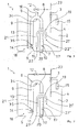
Außerdem ist der Wasserkasten 1 mit einem Auslöseventil 12 zum Auslösen des Spülvorgangs ausgerüstet. Das Auslöseventil 12 ist in einem Zuleitungsrohr 13 für einen in der Zeichnung nicht dargestellten Wasserstrahl zur Siphoneinheit 6 angeordnet; dessen Austrittsöffnung 14 vor dem Siphonbogen 8 stromaufwärts in das Steigrohr 9 der Siphoneinheit 6 mündet und in Richtung des Siphonbogens 8 gerichtet ist. Das Schwimmerventil 3 ist mit einem Schwimmer 15 ausgestattet. Außerdem ist der Siphonbogen 8. mit einem Belüftungsventil 16 an seiner höchsten Stelle ausgebildet.In addition, the
Von dem Füllraum 2 ist durch eine Trennwand 17 ein Ansaugraum 18 abgetrennt, in den das Steigrohr 9 mit dem Wassereingang 11 der Siphoneinheit 6 und das Zuleitungsrohr 13 mit der Austrittsöffnung 14 hinein ragt. Die Trennwand 17 erstreckt sich von dem Wasserkastenboden 5 weg in der unteren Hälfte des Wasserkastens 1. Im Bereich der Trennwand 17 ist ein U-förmiges Überlaufrohr 19 vorgesehen, dessen Schenkel 21, 21' die Trennwand 17 übergreifen und sich mit unterschiedlicher Länge in Richtung des Wasserkastenbodens 5 erstrecken. Dabei ist das Ende 22 des längeren Schenkel 21 im Ansaugraum 18 auf der Höhe des Wassereingangs 11 des Steigrohrs 9 angeordnet und das kürzere Ende 22' in dem verbleibenden Füllraum 2, in den auch der Wasserzulauf 4 des Wasserkastens 1 hinein ragt.From the filling
Der Wasserzulauf 4 dient zum Auffüllen des Füllraums 2 mit in der
Bei den in den
Das in der
Die
Die
Die
Claims (17)
Priority Applications (1)
| Application Number | Priority Date | Filing Date | Title |
|---|---|---|---|
| EP07019454A EP2045406A1 (en) | 2007-10-04 | 2007-10-04 | Toilet cistern with additional water injection and method for emptying |
Applications Claiming Priority (1)
| Application Number | Priority Date | Filing Date | Title |
|---|---|---|---|
| EP07019454A EP2045406A1 (en) | 2007-10-04 | 2007-10-04 | Toilet cistern with additional water injection and method for emptying |
Publications (1)
| Publication Number | Publication Date |
|---|---|
| EP2045406A1 true EP2045406A1 (en) | 2009-04-08 |
Family
ID=39124886
Family Applications (1)
| Application Number | Title | Priority Date | Filing Date |
|---|---|---|---|
| EP07019454A Withdrawn EP2045406A1 (en) | 2007-10-04 | 2007-10-04 | Toilet cistern with additional water injection and method for emptying |
Country Status (1)
| Country | Link |
|---|---|
| EP (1) | EP2045406A1 (en) |
Cited By (5)
| Publication number | Priority date | Publication date | Assignee | Title |
|---|---|---|---|---|
| WO2016016471A1 (en) * | 2014-08-01 | 2016-02-04 | Siamp Cedap | Device for toilets |
| CN105525666A (en) * | 2015-11-20 | 2016-04-27 | 刘光磊 | Ultra-clean closestool |
| CN105926735A (en) * | 2016-06-17 | 2016-09-07 | 厦门瑞尔特卫浴科技股份有限公司 | Drain device for draining water from water tank by aid of pressure difference |
| CN110886070A (en) * | 2018-09-07 | 2020-03-17 | 青岛海尔洗衣机有限公司 | Washing machine |
| CN113833076A (en) * | 2021-09-17 | 2021-12-24 | 谷力(厦门)科技有限公司 | Closestool flushing device suitable for low water pressure |
Citations (6)
| Publication number | Priority date | Publication date | Assignee | Title |
|---|---|---|---|---|
| CH110243A (en) * | 1924-06-17 | 1925-05-16 | Arnet Hans | Flushing device for toilets. |
| CH263599A (en) * | 1948-05-31 | 1949-09-15 | Ag Belco Sanitaere Apparate | Cistern for toilet and the like. |
| GB809078A (en) * | 1955-08-22 | 1959-02-18 | Ideal Boilers & Radiators Ltd | Improvements in or relating to devices for the flushing of water-closet bowls or the like |
| GB1512534A (en) * | 1976-09-24 | 1978-06-01 | Nat Res Dev | Water closet cisterns |
| EP0794292A1 (en) * | 1993-06-22 | 1997-09-10 | Gösta Leopold Hammarstedt | An actuating mechanism for flushing systems for water closets |
| GB2361483A (en) * | 2000-04-19 | 2001-10-24 | Philip Nash | Cistern overflow system |
-
2007
- 2007-10-04 EP EP07019454A patent/EP2045406A1/en not_active Withdrawn
Patent Citations (6)
| Publication number | Priority date | Publication date | Assignee | Title |
|---|---|---|---|---|
| CH110243A (en) * | 1924-06-17 | 1925-05-16 | Arnet Hans | Flushing device for toilets. |
| CH263599A (en) * | 1948-05-31 | 1949-09-15 | Ag Belco Sanitaere Apparate | Cistern for toilet and the like. |
| GB809078A (en) * | 1955-08-22 | 1959-02-18 | Ideal Boilers & Radiators Ltd | Improvements in or relating to devices for the flushing of water-closet bowls or the like |
| GB1512534A (en) * | 1976-09-24 | 1978-06-01 | Nat Res Dev | Water closet cisterns |
| EP0794292A1 (en) * | 1993-06-22 | 1997-09-10 | Gösta Leopold Hammarstedt | An actuating mechanism for flushing systems for water closets |
| GB2361483A (en) * | 2000-04-19 | 2001-10-24 | Philip Nash | Cistern overflow system |
Cited By (9)
| Publication number | Priority date | Publication date | Assignee | Title |
|---|---|---|---|---|
| WO2016016471A1 (en) * | 2014-08-01 | 2016-02-04 | Siamp Cedap | Device for toilets |
| FR3024475A1 (en) * | 2014-08-01 | 2016-02-05 | Siamp Cedap Reunies | TOILET DEVICE |
| EA039580B1 (en) * | 2014-08-01 | 2022-02-14 | Сиамп Седап | Device for toilets |
| CN105525666A (en) * | 2015-11-20 | 2016-04-27 | 刘光磊 | Ultra-clean closestool |
| CN105926735A (en) * | 2016-06-17 | 2016-09-07 | 厦门瑞尔特卫浴科技股份有限公司 | Drain device for draining water from water tank by aid of pressure difference |
| CN110886070A (en) * | 2018-09-07 | 2020-03-17 | 青岛海尔洗衣机有限公司 | Washing machine |
| CN110886070B (en) * | 2018-09-07 | 2022-09-16 | 青岛海尔洗衣机有限公司 | Washing machine |
| CN113833076A (en) * | 2021-09-17 | 2021-12-24 | 谷力(厦门)科技有限公司 | Closestool flushing device suitable for low water pressure |
| CN113833076B (en) * | 2021-09-17 | 2024-01-09 | 谷力(厦门)科技有限公司 | Toilet flushing device suitable for low water pressure |
Similar Documents
| Publication | Publication Date | Title |
|---|---|---|
| DE2637962A1 (en) | VACUUM DRAINAGE SYSTEM | |
| EP2641876B1 (en) | Biological wastewater treatment device | |
| EP2045406A1 (en) | Toilet cistern with additional water injection and method for emptying | |
| DE2440853C3 (en) | Flush toilet | |
| EP1854926B1 (en) | Outlet device for a flushing cistern | |
| EP2535317B1 (en) | Biological clarifying device | |
| EP2447131B1 (en) | Valve assembly for the removal of a liquid medium and method for controlling a valve assembly | |
| EP1526222B1 (en) | Flushing tank comprising a diverter | |
| DE3822392A1 (en) | Washing machine with at least one fresh-water feed conduit | |
| EP1449968B1 (en) | Water cistern for a closet and corresponding closet | |
| EP2080839A1 (en) | Sanitary flushing assembly comprising a device for adding a cleaning agent and/or a fragrance | |
| DE102006010569A1 (en) | Vacuum sewer facility | |
| DE1902751A1 (en) | Water closet | |
| WO2003104574A1 (en) | Toilet system and method for operating such a toilet system | |
| DE102012110773B4 (en) | Pumping station and process for pumping wastewater | |
| AT280901B (en) | Siphon valve for a liquid container | |
| EP1175534B1 (en) | Water-saving toilet arrangement | |
| DE102012211655A1 (en) | Shower toilet, has shower arm arranged in region of upper end of toilet bowl, and overflow aperture that is spaced from lowest point of shower arm when overflow aperture is inserted into interior space | |
| DE3518951A1 (en) | Storage and flushing device for a periodically filled tank, in particular for a stormwater tank | |
| EP4095323B1 (en) | Flushing system | |
| CH611368A5 (en) | Vacuum sewerage system | |
| EP4095324A1 (en) | Flushing system | |
| DE3738270C2 (en) | ||
| DE233141C (en) | ||
| EP1321590B1 (en) | Apparatus for flushing toilet bowl with help of pressurised water plug |
Legal Events
| Date | Code | Title | Description |
|---|---|---|---|
| PUAI | Public reference made under article 153(3) epc to a published international application that has entered the european phase |
Free format text: ORIGINAL CODE: 0009012 |
|
| AK | Designated contracting states |
Kind code of ref document: A1 Designated state(s): AT BE BG CH CY CZ DE DK EE ES FI FR GB GR HU IE IS IT LI LT LU LV MC MT NL PL PT RO SE SI SK TR |
|
| AX | Request for extension of the european patent |
Extension state: AL BA HR MK RS |
|
| AKX | Designation fees paid | ||
| STAA | Information on the status of an ep patent application or granted ep patent |
Free format text: STATUS: THE APPLICATION IS DEEMED TO BE WITHDRAWN |
|
| 18D | Application deemed to be withdrawn |
Effective date: 20091009 |
|
| REG | Reference to a national code |
Ref country code: DE Ref legal event code: 8566 |