EP2045133A2 - Vehicle periphery monitoring apparatus and image displaying method - Google Patents
Vehicle periphery monitoring apparatus and image displaying method Download PDFInfo
- Publication number
- EP2045133A2 EP2045133A2 EP08164852A EP08164852A EP2045133A2 EP 2045133 A2 EP2045133 A2 EP 2045133A2 EP 08164852 A EP08164852 A EP 08164852A EP 08164852 A EP08164852 A EP 08164852A EP 2045133 A2 EP2045133 A2 EP 2045133A2
- Authority
- EP
- European Patent Office
- Prior art keywords
- image
- region
- vehicle
- host vehicle
- blind spot
- Prior art date
- Legal status (The legal status is an assumption and is not a legal conclusion. Google has not performed a legal analysis and makes no representation as to the accuracy of the status listed.)
- Granted
Links
- 238000012544 monitoring process Methods 0.000 title claims abstract description 57
- 238000000034 method Methods 0.000 title claims description 15
- 238000012545 processing Methods 0.000 claims abstract description 53
- 230000000903 blocking effect Effects 0.000 claims description 7
- 230000004044 response Effects 0.000 claims description 6
- 238000001514 detection method Methods 0.000 claims description 4
- 230000001419 dependent effect Effects 0.000 claims 1
- 238000010586 diagram Methods 0.000 description 35
- 230000015654 memory Effects 0.000 description 28
- 239000000470 constituent Substances 0.000 description 6
- 230000008859 change Effects 0.000 description 5
- 230000006870 function Effects 0.000 description 4
- 238000003708 edge detection Methods 0.000 description 3
- 238000005516 engineering process Methods 0.000 description 3
- 238000003909 pattern recognition Methods 0.000 description 3
- 238000013459 approach Methods 0.000 description 2
- 238000012986 modification Methods 0.000 description 2
- 230000004048 modification Effects 0.000 description 2
- 230000009977 dual effect Effects 0.000 description 1
- 230000003287 optical effect Effects 0.000 description 1
- 238000012552 review Methods 0.000 description 1
Images


Classifications
-
- B—PERFORMING OPERATIONS; TRANSPORTING
- B60—VEHICLES IN GENERAL
- B60R—VEHICLES, VEHICLE FITTINGS, OR VEHICLE PARTS, NOT OTHERWISE PROVIDED FOR
- B60R1/00—Optical viewing arrangements; Real-time viewing arrangements for drivers or passengers using optical image capturing systems, e.g. cameras or video systems specially adapted for use in or on vehicles
- B60R1/20—Real-time viewing arrangements for drivers or passengers using optical image capturing systems, e.g. cameras or video systems specially adapted for use in or on vehicles
- B60R1/22—Real-time viewing arrangements for drivers or passengers using optical image capturing systems, e.g. cameras or video systems specially adapted for use in or on vehicles for viewing an area outside the vehicle, e.g. the exterior of the vehicle
- B60R1/23—Real-time viewing arrangements for drivers or passengers using optical image capturing systems, e.g. cameras or video systems specially adapted for use in or on vehicles for viewing an area outside the vehicle, e.g. the exterior of the vehicle with a predetermined field of view
- B60R1/26—Real-time viewing arrangements for drivers or passengers using optical image capturing systems, e.g. cameras or video systems specially adapted for use in or on vehicles for viewing an area outside the vehicle, e.g. the exterior of the vehicle with a predetermined field of view to the rear of the vehicle
-
- B—PERFORMING OPERATIONS; TRANSPORTING
- B60—VEHICLES IN GENERAL
- B60R—VEHICLES, VEHICLE FITTINGS, OR VEHICLE PARTS, NOT OTHERWISE PROVIDED FOR
- B60R1/00—Optical viewing arrangements; Real-time viewing arrangements for drivers or passengers using optical image capturing systems, e.g. cameras or video systems specially adapted for use in or on vehicles
- B60R1/20—Real-time viewing arrangements for drivers or passengers using optical image capturing systems, e.g. cameras or video systems specially adapted for use in or on vehicles
- B60R1/22—Real-time viewing arrangements for drivers or passengers using optical image capturing systems, e.g. cameras or video systems specially adapted for use in or on vehicles for viewing an area outside the vehicle, e.g. the exterior of the vehicle
- B60R1/28—Real-time viewing arrangements for drivers or passengers using optical image capturing systems, e.g. cameras or video systems specially adapted for use in or on vehicles for viewing an area outside the vehicle, e.g. the exterior of the vehicle with an adjustable field of view
-
- G—PHYSICS
- G01—MEASURING; TESTING
- G01S—RADIO DIRECTION-FINDING; RADIO NAVIGATION; DETERMINING DISTANCE OR VELOCITY BY USE OF RADIO WAVES; LOCATING OR PRESENCE-DETECTING BY USE OF THE REFLECTION OR RERADIATION OF RADIO WAVES; ANALOGOUS ARRANGEMENTS USING OTHER WAVES
- G01S13/00—Systems using the reflection or reradiation of radio waves, e.g. radar systems; Analogous systems using reflection or reradiation of waves whose nature or wavelength is irrelevant or unspecified
- G01S13/88—Radar or analogous systems specially adapted for specific applications
- G01S13/93—Radar or analogous systems specially adapted for specific applications for anti-collision purposes
- G01S13/931—Radar or analogous systems specially adapted for specific applications for anti-collision purposes of land vehicles
-
- B—PERFORMING OPERATIONS; TRANSPORTING
- B60—VEHICLES IN GENERAL
- B60R—VEHICLES, VEHICLE FITTINGS, OR VEHICLE PARTS, NOT OTHERWISE PROVIDED FOR
- B60R2300/00—Details of viewing arrangements using cameras and displays, specially adapted for use in a vehicle
- B60R2300/10—Details of viewing arrangements using cameras and displays, specially adapted for use in a vehicle characterised by the type of camera system used
- B60R2300/105—Details of viewing arrangements using cameras and displays, specially adapted for use in a vehicle characterised by the type of camera system used using multiple cameras
-
- B—PERFORMING OPERATIONS; TRANSPORTING
- B60—VEHICLES IN GENERAL
- B60R—VEHICLES, VEHICLE FITTINGS, OR VEHICLE PARTS, NOT OTHERWISE PROVIDED FOR
- B60R2300/00—Details of viewing arrangements using cameras and displays, specially adapted for use in a vehicle
- B60R2300/30—Details of viewing arrangements using cameras and displays, specially adapted for use in a vehicle characterised by the type of image processing
- B60R2300/303—Details of viewing arrangements using cameras and displays, specially adapted for use in a vehicle characterised by the type of image processing using joined images, e.g. multiple camera images
-
- B—PERFORMING OPERATIONS; TRANSPORTING
- B60—VEHICLES IN GENERAL
- B60R—VEHICLES, VEHICLE FITTINGS, OR VEHICLE PARTS, NOT OTHERWISE PROVIDED FOR
- B60R2300/00—Details of viewing arrangements using cameras and displays, specially adapted for use in a vehicle
- B60R2300/70—Details of viewing arrangements using cameras and displays, specially adapted for use in a vehicle characterised by an event-triggered choice to display a specific image among a selection of captured images
-
- B—PERFORMING OPERATIONS; TRANSPORTING
- B60—VEHICLES IN GENERAL
- B60R—VEHICLES, VEHICLE FITTINGS, OR VEHICLE PARTS, NOT OTHERWISE PROVIDED FOR
- B60R2300/00—Details of viewing arrangements using cameras and displays, specially adapted for use in a vehicle
- B60R2300/80—Details of viewing arrangements using cameras and displays, specially adapted for use in a vehicle characterised by the intended use of the viewing arrangement
- B60R2300/804—Details of viewing arrangements using cameras and displays, specially adapted for use in a vehicle characterised by the intended use of the viewing arrangement for lane monitoring
-
- B—PERFORMING OPERATIONS; TRANSPORTING
- B60—VEHICLES IN GENERAL
- B60R—VEHICLES, VEHICLE FITTINGS, OR VEHICLE PARTS, NOT OTHERWISE PROVIDED FOR
- B60R2300/00—Details of viewing arrangements using cameras and displays, specially adapted for use in a vehicle
- B60R2300/80—Details of viewing arrangements using cameras and displays, specially adapted for use in a vehicle characterised by the intended use of the viewing arrangement
- B60R2300/8046—Details of viewing arrangements using cameras and displays, specially adapted for use in a vehicle characterised by the intended use of the viewing arrangement for replacing a rear-view mirror system
-
- B—PERFORMING OPERATIONS; TRANSPORTING
- B60—VEHICLES IN GENERAL
- B60R—VEHICLES, VEHICLE FITTINGS, OR VEHICLE PARTS, NOT OTHERWISE PROVIDED FOR
- B60R2300/00—Details of viewing arrangements using cameras and displays, specially adapted for use in a vehicle
- B60R2300/80—Details of viewing arrangements using cameras and displays, specially adapted for use in a vehicle characterised by the intended use of the viewing arrangement
- B60R2300/8066—Details of viewing arrangements using cameras and displays, specially adapted for use in a vehicle characterised by the intended use of the viewing arrangement for monitoring rearward traffic
-
- G—PHYSICS
- G01—MEASURING; TESTING
- G01S—RADIO DIRECTION-FINDING; RADIO NAVIGATION; DETERMINING DISTANCE OR VELOCITY BY USE OF RADIO WAVES; LOCATING OR PRESENCE-DETECTING BY USE OF THE REFLECTION OR RERADIATION OF RADIO WAVES; ANALOGOUS ARRANGEMENTS USING OTHER WAVES
- G01S13/00—Systems using the reflection or reradiation of radio waves, e.g. radar systems; Analogous systems using reflection or reradiation of waves whose nature or wavelength is irrelevant or unspecified
- G01S13/86—Combinations of radar systems with non-radar systems, e.g. sonar, direction finder
-
- G—PHYSICS
- G01—MEASURING; TESTING
- G01S—RADIO DIRECTION-FINDING; RADIO NAVIGATION; DETERMINING DISTANCE OR VELOCITY BY USE OF RADIO WAVES; LOCATING OR PRESENCE-DETECTING BY USE OF THE REFLECTION OR RERADIATION OF RADIO WAVES; ANALOGOUS ARRANGEMENTS USING OTHER WAVES
- G01S13/00—Systems using the reflection or reradiation of radio waves, e.g. radar systems; Analogous systems using reflection or reradiation of waves whose nature or wavelength is irrelevant or unspecified
- G01S13/88—Radar or analogous systems specially adapted for specific applications
- G01S13/93—Radar or analogous systems specially adapted for specific applications for anti-collision purposes
- G01S13/931—Radar or analogous systems specially adapted for specific applications for anti-collision purposes of land vehicles
- G01S2013/9315—Monitoring blind spots
-
- G—PHYSICS
- G01—MEASURING; TESTING
- G01S—RADIO DIRECTION-FINDING; RADIO NAVIGATION; DETERMINING DISTANCE OR VELOCITY BY USE OF RADIO WAVES; LOCATING OR PRESENCE-DETECTING BY USE OF THE REFLECTION OR RERADIATION OF RADIO WAVES; ANALOGOUS ARRANGEMENTS USING OTHER WAVES
- G01S13/00—Systems using the reflection or reradiation of radio waves, e.g. radar systems; Analogous systems using reflection or reradiation of waves whose nature or wavelength is irrelevant or unspecified
- G01S13/88—Radar or analogous systems specially adapted for specific applications
- G01S13/93—Radar or analogous systems specially adapted for specific applications for anti-collision purposes
- G01S13/931—Radar or analogous systems specially adapted for specific applications for anti-collision purposes of land vehicles
- G01S2013/9322—Radar or analogous systems specially adapted for specific applications for anti-collision purposes of land vehicles using additional data, e.g. driver condition, road state or weather data
Definitions
- the present invention relates to a vehicle periphery monitoring apparatus and an image displaying method and particularly, but not exclusively, to an apparatus and method for presenting an image of a region rearward of a vehicle and a region laterally rearward of the vehicle to a driver. Aspects of the invention relate to an apparatus, to a method and to a vehicle.
- an onboard (vehicle-mounted) camera has been used to photograph an image of a region rearward of a vehicle and a region laterally rearward of the vehicle.
- the image is then displayed on a display device installed inside the vehicle so that a driver can accurately ascertain a situation in the regions directly rearward and laterally rearward of the vehicle. This is accomplished with a small amount of change in a viewing direction while securing a view of a region corresponding to a blind spot of an interior rearview mirror and a door mirror of the vehicle.
- Japanese Laid-Open Patent Publication No. 2003-81014 discloses a vehicle periphery monitoring apparatus that uses a rearward camera installed on a rear end portion of a vehicle to photograph an image of a region rearward of the vehicle and a pair of lateral cameras installed on a left door mirror and a right door mirror of the vehicle to photograph images of regions laterally rearward of the vehicle.
- This conventional vehicle periphery monitoring apparatus displays the images on a single display device arranged inside the vehicle. The images are displayed horizontally side by side on the display device so that the image of the region rearward of the vehicle is placed between the images of the regions laterally (left and right) rearward of the vehicle.
- Embodiments of the invention may provide a vehicle periphery monitoring apparatus and an image display method that can display a relatively easily recognizable image for a driver of a host vehicle.
- Other aims and advantages of the invention will become apparent from the following description, claims and drawings.
- a vehicle periphery monitoring apparatus comprising an image capturing device configured and arranged to capture an image of a region rearward of a host vehicle equipped with the vehicle periphery monitoring apparatus and an image of a region laterally rearward of the host vehicle, a display device mounted in an interior of the host vehicle, a blind spot determining section configured and arranged to determine that a following vehicle created blind spot region exists in the region laterally rearward of the host vehicle upon detecting a parameter indicative of a following vehicle blocking an area of the region laterally rearward of the host vehicle and a processing section configured to switch a displayed image on the display device from a first display image to a second display image in response to the blind spot determining section determining that the following vehicle created blind spot region exists, the first display image including the image of the region rearward of the host vehicle, and the second display image including at least a portion of the image of the region laterally rearward of the host vehicle that encompasses the following vehicle created blind spot region which is absent
- the image capturing device includes a first image capturing section configured and arranged to capture a first image including the image of the region rearward of the host vehicle and the region laterally rearward of the host vehicle, and a second image capturing section configured and arranged to capture a second image including the image of the region laterally rearward of the host vehicle from a different viewpoint than the first image capturing section.
- the processing section is configured to generate the first display image using the first image captured by the first image capturing section, and to generate the second display image by combining at least a portion of the second image including the following vehicle created blind spot region captured by the second image capturing section with the first image captured by the first image capturing section.
- the processing section is configured to generate the second display image by superimposing at least a portion of the second image including the following vehicle created blind spot region captured by the second image capturing section onto the first image captured by the first image capturing section.
- the processing section is configured to generate the second display image by arranging at least a portion of the second image including the following vehicle created blind spot region captured by the second image capturing section alongside the first image captured by the first image capturing section.
- the blind spot determining section is configured to determine that the following vehicle created blind spot region exists when a distance between the host vehicle and the following vehicle exceeds a prescribed threshold value.
- the blind spot determining section is configured to determine that the following vehicle created blind spot exists by processing the first image.
- the apparatus may comprise a following vehicle detecting device configured and arranged to detect the following vehicle traveling behind the host vehicle, the blind spot determining section being configured to determine that the following vehicle created blind spot region exists based on a detection result by the following vehicle detecting device.
- the apparatus may comprise an obstacle detecting device configured and arranged to detect whether an obstacle exists between the host vehicle and the following vehicle, the processing section being configured to superimpose an indicia indicative of the obstacle detected by the obstacle detecting device on the second display image.
- the processing section is configured to generate the first display image by enlarging the image of the region rearward of the host vehicle captured by the image capturing device.
- the image capturing device further includes a third image capturing section configured and arranged to capture a third image including an image of a region laterally rearward of the vehicle disposed on an opposite side from the region laterally rearward of the vehicle encompassed in the second image with respect to the region rearward of the vehicle in the first image, and the processing section is configured to generate the second display image by combining at least portions of the second and third images including the following vehicle created blind spot region captured by the second and third image capturing sections with the first image captured by the first image capturing section.
- the image capturing device includes a single camera configured and arranged to produce both the first and second display images.
- the image capturing device is configured and arranged to sequentially capture the image of the region rearward of the host vehicle and the image of a region laterally rearward of the host vehicle
- the processing section is configured to sequentially output one of the first and second display images to form a plurality of frames of a video sequence displayed on the display device.
- a vehicle periphery monitoring apparatus comprising image capturing means for capturing an image of a region rearward of a host vehicle equipped with the vehicle periphery monitoring apparatus and an image of a region laterally rearward of the host vehicle, display means for displaying the images captured by the image capturing means, blind spot determining means for determining that a following vehicle created blind spot region exists in the region laterally rearward of the host vehicle upon detecting a parameter indicative of a following vehicle blocking an area of the region laterally rearward of the host vehicle and processing means for switching a display image displayed on the display means from a first display image to a second display image in response to the blind spot determining means determining that the following vehicle created blind spot region exists, the first display image including the image of the region rearward of the host vehicle, and the second display image including at least a portion of the image of the region laterally rearward of the host vehicle that encompasses the following vehicle created blind spot region which is absent from the first display image.
- a vehicle periphery monitoring method comprising capturing an image of a region rearward of a host vehicle equipped with the vehicle periphery monitoring apparatus and an image of a region laterally rearward of the host vehicle, determining that a following vehicle created blind spot region exists in the region laterally rearward of the host vehicle upon detecting a parameter indicative of a following vehicle blocking an area of the region laterally rearward of the host vehicle and switching a display image displayed on a display device from a first display image to a second display image in response to determining that the following vehicle created blind spot region, the first display image including the image of the region rearward of the host vehicle, and the second display image including at least a portion of the image of the region laterally rearward of the host vehicle that encompasses the following vehicle created blind spot region which is absent from the first display image.
- a vehicle periphery monitoring apparatus may include an image capturing device, a display device, a blind spot determining section, and a processing section.
- the image capturing device is configured and arranged to capture an image of a region rearward of a host vehicle equipped with the vehicle periphery monitoring apparatus and an image of a region laterally rearward of the host vehicle.
- the display device is mounted in an interior of the host vehicle.
- the blind spot determining section is configured and arranged to determine that a following vehicle created blind spot region exists in the region laterally rearward of the host vehicle upon detecting a parameter indicative of a following vehicle blocking an area of the region laterally rearward of the host vehicle.
- the processing section is configured to switch a displayed image on the display device from a first display image to a second display image in response to the blind spot determining section determining that the following vehicle created blind spot region exists.
- the first display image includes the image of the region rearward of the host vehicle
- the second display image includes at least a portion of the image of the region laterally rearward of the host vehicle that encompasses the following vehicle created blind spot region which is absent from the first display image.
- a vehicle periphery monitoring apparatus is illustrated in accordance with a first embodiment of the present invention.
- the vehicle periphery monitoring apparatus is configured and arranged to capture images of a region directly rearward of and laterally rearward of a vehicle in which the vehicle periphery monitoring apparatus is employed (hereinafter called "the host vehicle V") by using a plurality of (i.e., three) onboard video cameras mounted on the host vehicle V.
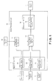
- Figure 1 is a simplified block diagram showing the constituent features of the vehicle periphery monitoring apparatus in accordance with the first embodiment.
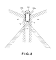
- Figure 2 is a schematic diagram illustrating an example of an arrangement of the three onboard cameras.
- the vehicle periphery monitoring apparatus has three onboard video cameras including a rear video camera 1, a right side video camera 2 and a left side video camera 3, which collectively constitute an image capturing device.
- the rear camera 1 is installed on a rearward portion of the host vehicle V
- the right side camera 2 is installed on a right lateral portion of the host vehicle V
- the left side camera 3 is installed on a left lateral portion of the host vehicle V.
- the vehicle periphery monitoring apparatus also includes an image processing unit 10 configured to generate an image to be displayed (displayed image) using the images captured by the rear camera 1, the right side camera 2 and the left side camera 3 and a display device (image displaying device) 4 configured to display the display image generated by the image processing unit 10.
- an image processing unit 10 configured to generate an image to be displayed (displayed image) using the images captured by the rear camera 1, the right side camera 2 and the left side camera 3
- a display device (image displaying device) 4 configured to display the display image generated by the image processing unit 10.
- the rear camera 1 is installed in a prescribed position on a rearward portion of the host vehicle V, e.g., on a roof spoiler.
- the rear camera 1 is configured and arranged to capture an image of a relatively large region located directly rearward and laterally rearward of the host vehicle V.
- the region A1 shown in Figure 2 is an example of the region photographed by the rear camera 1.
- the right side camera 2 is installed in a prescribed position on a right lateral portion of the host vehicle V, e.g., on a right door mirror DM R .
- the right side camera 2 is configured and arranged to capture an image of a relatively large region located laterally rearward from the right side of the host vehicle V.
- the right side camera 2 is thus configured and arranged to photograph from a different view point than the rear camera 1. Therefore, the rear camera 1 corresponds to the first image capturing section, and the right side camera 2 and the left side camera 3 correspond to the second and third image capturing sections of the first embodiment.
- the region A2 shown in Figure 2 is an example of the region photographed by the right side camera 2.
- the left side camera 3 is installed in a prescribed position on a left lateral portion of the host vehicle V, e.g., on a left door mirror DM L .
- the left side camera 3 is configured and arranged to capture an image of a relatively large region located laterally rearward from the left side of the host vehicle V.
- the left side camera 3 is thus arranged to photograph from a different view point than the rear camera 1.
- the region A3 shown in Figure 2 is an example of the region photographed by the left side camera 3.
- the region rearward of the host vehicle V is a prescribed region centered on a longitudinal center axis of the host vehicle V extended rearwardly from the host vehicle V, e.g., a region corresponding to a region that could be viewed in a rearview mirror RM by a driver of the host vehicle V.
- the region laterally rearward of the host vehicle V refers to regions positioned on the left and right outer sides of the region rearward of the host vehicle V and corresponds to, for example, regions that the driver of the host vehicle V can view in the left and right door mirrors DM L and DM R .
- Each of the rear camera 1, the right side camera 2 and the left side camera 3 is arranged as a conventional video camera having an optical system comprising a lens and a light-receiving element, e.g., a CCD element or a CMOS element.
- a light-receiving element e.g., a CCD element or a CMOS element.
- Light that passes through the lens and strikes the light-receiving element is converted into an electric signal and outputted as an image signal comprising a numerical value for each pixel of the photographed image.
- the image signal outputted from the rear camera 1, the right side camera 2 and the left side camera 3 is received by the image processing unit 10.
- the image processing unit 10 is configured to generate a display image using the images captured by the rear camera 1, the right side camera 2 and the left side camera 3 and to display the generated display image on the display device 4 installed inside the host vehicle V.
- the image of a region rearward of the host vehicle V captured by the rear camera 1 is enlarged in the display image that is generated and displayed on the display device 4.
- an image of a region rearward of the host vehicle V can be displayed such that the driver of the host vehicle V can correctly perceive a distance based on the image, and required information can be presented to the driver of the host vehicle V in an accurate manner when the blind spot region exists due to a following vehicle being close to the host vehicle V.
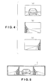
- Figure 4 is a series of schematic diagrams (a) to (c) showing examples of the images captured by the rear camera 1, the right side camera 2 and the left side camera 3 during the traffic situation shown in Figure 3 .
- the diagram (a) of Figure 4 is a schematic view of an image of a region rearward of the host vehicle V captured by the rear camera 1
- the diagram (b) of Figure 4 is a schematic view of an image of a region laterally rightward and rearward of the host vehicle V captured by the right side camera 2
- the diagram (c) of Figure 4 is a schematic view of an image of a region laterally leftward and rearward of the host vehicle V captured by the left side camera 3.
- Figure 5 is a schematic diagram of an example of the display image displayed on the display device 4 when the images shown in the diagrams (a) to (c) are arranged side by side into a display image matched to the size of the display region of the display device 4 in a comparison example.
- the display image shown in Figure 5 enables to present the situation existing in a wide region spanning rearward and rearwardly leftward and rightward of the host vehicle V to the driver of the host vehicle V, the size of the following vehicle V1 appears smaller in the display image on the display device 4 than it would in a mirror reflection image of the rearview mirror RM. Consequently, there is the possibility that the driver will perceive the distance from the host vehicle V to the following vehicle V1 incorrectly.
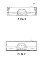
- the mirror reflection image of a region rearward of the host vehicle V that the driver would view in the rearview mirror RM of the host vehicle V would appear, for example, as shown in Figure 6 . Since the driver of the host vehicle V is accustomed to viewing a mirror reflection image of the rearview mirror RM, the driver tends to determine a distance to an object based on the size of the object in the mirror reflection image.
- a feasibly effective way to avoid such a problem is to display only the rearward image captured by the rear camera 1 on the display device 4 and enlarge the image photographed by the rear camera 1 such that the size of the display image displayed on the display device 4 is substantially equal to the size of a mirror reflection image viewed in the rearview mirror RM as shown in Figure 7 . In this way, the headway distance between the host vehicle V and the following vehicle V1 can be perceived by the driver more easily.
- This approach is also advantageous in that it is easier to grasp the situation existing rearward of the host vehicle V when viewing an image from a single viewpoint than when viewing images captured from a plurality of viewpoints (e.g., the rear camera 1, the right side camera 2 and the left side camera 3) and displayed in the manner shown in Figure 5 .
- a plurality of viewpoints e.g., the rear camera 1, the right side camera 2 and the left side camera 3
- the display image like the one shown in Figure 7 a different problem may occur in a different traffic situation such that the vehicle periphery monitoring apparatus is not able to present required information to the driver of the host vehicle V in an appropriate manner.
- a large following vehicle V2 e.g., a truck
- another following vehicle V3 is traveling along side the following vehicle V2 in the adjacent lane to the right of the lane in which the host vehicle V is traveling.
- a blind spot region (the following vehicle created blind spot region) that cannot be photographed by the rear camera 1 exists to the side of the following vehicle V2 as shown in Figure 8 .
- the blind spot region is also created on the left side rearward region of the host vehicle V due to the existence of the following vehicle V2.
- the image processing unit 10 is configured and arranged to determine whether a blind spot region that cannot be photographed by the rear camera 1 exists laterally of a following vehicle due to the following vehicle being close to the host vehicle V. While a blind spot region does not exist, the image of a region rearward of the host vehicle V captured by the rear camera 1 is displayed on the display device 4 such that it is enlarged into an image size equivalent to a mirror reflection image of a rearview mirror (as shown in Figure 6 ).
- images of the blind spot region captured by the right side camera 2 and the left side camera 3 are combined with the image of a region rearward of the host vehicle V captured by the rear camera 1 to generate a display image (second display image) shown in, for example, Figure 10 or 11 to be displayed on the display device 4.
- images R2 and R3 of the blind spot regions captured by the right side camera 2 and the left side camera, respectively are superimposed on an image R1 captured by the rear camera 1 in a position generally corresponding to where the blind spot regions are.
- the images R2 and R3 of the blind spot regions captured by the right side camera 2 and the left side camera 3 are arranged adjacently on the right side and left side of the rearward image R1 captured by the rear camera 1.
- the image processing unit 10 includes an image input section 11, a blind spot determining section (determining device) 12, a display image generating section (processing section) 13, and an image output section 14.
- the image processing unit 10 includes a microcomputer with an image processing control program that controls the image input section 11, the blind spot determining section 12, the display image generating section 13 and the image output section 14 as discussed below.
- the image processing unit 10 can also include other conventional components such as an input interface circuit, an output interface circuit, and storage devices such as a ROM (Read Only Memory) device and a RAM (Random Access Memory) device.
- the microcomputer of the image processing unit 10 is programmed to control the display device 4 and other components of the vehicle periphery monitoring apparatus.
- the memory circuit stores processing results and control programs such as the ones for blind spot determining operation and image converting operation that are run by the processor circuit.
- the image processing unit 10 is operatively coupled to the rear camera 1, the right side camera 2, the left side camera 3, and the display device 4 in a conventional manner.
- the image input section 11 of the image processing unit 10 is configured to separately receive the images captured by the three onboard cameras, i.e., the rear camera 1, the right side camera 2 and the left side camera 3.
- the image input section 11 includes three input image frame memories 21, 22 and 23 each comprising a RAM.
- the input image frame memory 21 corresponds to the rear camera 1
- the input image frame memory 22 corresponds to the right side camera 2
- the input image frame memory 23 corresponds to the left side camera 3.
- the images captured by the rear camera 1, the right side camera 2, and the left side camera 3 are each converted into a digital signal in accordance with the frame size of the input image and stored frame by frame in the input image frame memories 21, 22 and 23, respectively.
- the blind spot determining section 12 of the image processing unit 10 is configured to determine whether a blind spot region (following vehicle created blind spot region) that cannot be photographed by the rear camera 1 exists laterally of a following vehicle due to the following vehicle being close to the host vehicle V. More specifically, the blind spot determining section 12 is configured to determine that the following vehicle created blind spot region exists in the region laterally rearward of the host vehicle upon detecting a parameter indicative of a following vehicle blocking an area of the region laterally rearward of the host vehicle V.
- the blind spot determining section 12 is configured to apply conventional image processing techniques such as edge detection and pattern recognition to the image captured by the rear camera 1 and stored in the input image frame memory 21 of the image input section 11 in order to detect a following vehicle approaching closely behind the host vehicle V in the same lane as the host vehicle V.
- the blind spot determining section 12 is configured to approximate the shape of the following vehicle with a rectangular frame F, as shown in Figure 12 .
- the blind spot determining section 12 is configured to calculate the position and size of the following vehicle based on the position and size of the frame F in the image captured by the rear camera 1.
- the relationship between the actual position of the following vehicle in the region rearward of the host vehicle V and the position of the following vehicle in a coordinate system established in the image captured by the rear camera 1 can be specified in a unique manner based on the position and angle at which the rear camera 1 is installed and the angle of view of the rear camera 1. Consequently, the position of the following vehicle in the region rearward of the host vehicle V (i.e., the headway distance between the host vehicle V and the following vehicle) can be calculated based on the position of the bottom edge of the frame F in the image photographed by the rear camera 1. Then, based on the calculated position of the following vehicle, the size (vehicle width) of the following vehicle can be calculated based on the horizontal width of the frame F in the image photographed by the rear camera 1.
- the position and size of the following vehicle are calculated by executing image processing with respect to the rearward image captured by the rear camera 1
- the size and position of the following vehicle can also be calculated based on information detected by a conventional onboard object detecting device (e.g., a milliwave radar 15 or a laser radar) if such an object detecting device is installed on the host vehicle V.
- the size and position of the following vehicle can also be calculated based on both the results of an image processing applied to the image captured by the rear camera 1 and information detected by the onboard object detecting device.
- the blind spot determining section 12 is configured to determine whether the close proximity of the following vehicle has caused a blind spot region that cannot be photographed by the rear camera 1 to develop laterally of the same following vehicle.
- the host vehicle V is traveling in the middle lane of a three lane road and the following vehicle V2 (e.g., a truck) is traveling behind the host vehicle V as shown in Figure 13 .
- the following vehicle V2 e.g., a truck
- a distance L1 from the host vehicle V to the following vehicle V2 and a width W of the following vehicle V2 are detected according to the procedure described above.
- a hypothetical point M1 is set at a position where a line extended in the transverse direction of the host vehicle V from an edge portion of the host vehicle V where the rear camera 1 is installed intersects with a centerline C of an adjacent lane
- a hypothetical point M2 is set at a position where a line L3 extended from the rear camera 1 so as to contact an edge portion of the following vehicle V2 intersects the centerline C. If a distance L2 between the two points M1 and M2 is equal to or smaller than a prescribed threshold value, then the blind spot determining section 12 is configured to determine that a blind spot exists laterally of the following vehicle V2.
- the blind spot determining section 12 can also be configured to simply determine that a blind spot region exists laterally of the following vehicle V2 when the headway distance L1 between the host vehicle V and the following vehicle V2 is equal to or smaller than a prescribed threshold value.
- blind spot region refers to a blind spot that is large enough to substantially hide another following vehicle or two wheeled vehicle traveling in an adjacent lane.
- the blind spot determining section 12 is configured to determine whether a blind spot region that cannot be photographed by the rear camera 1 exists laterally of a following vehicle due to the close proximity of the following vehicle. If the blind spot determining section 12 determines that a blind spot region exists, then the blind spot determining section 12 is configured to send information indicating that the blind spot region exists to the display image generating section 13.
- the display image generating section 13 is configured to use the image captured by the rear camera 1 to generate a display image in which the image of the region rearward of the host vehicle V is enlarged into an image size equivalent to a mirror reflection image of the rearview mirror RM, as shown in, for example, Figure 7 . If the display region of the display device 4 is large enough, it is acceptable to generate a display image that includes an image of a region laterally rearward of the host vehicle V in the display image in addition to an image of the region rearward of the host vehicle V.
- the display image generating section 13 is configured to generate the display image by taking the pixel data of an image that was captured by the rear camera 1 and stored as a frame in the input image frame memory 21 of the image input section 11 and rearranging the pixel data into an output image frame memory 24 of the image output section 14 based on a definition table.
- the definition table used here stipulates the correspondence between each pixel stored in the output image frame memory 24 and a coordinate system (camera coordinate system) of the input image frame memory 21, i.e., the location of each pixel in the coordinate system, for a case in which the image of the region rearward of the host vehicle V captured by the rear camera 1 will be enlarged to an image size equivalent to a mirror reflection image of the rearview mirror RM.
- the rear camera 1 can be provided with a zoom in/out function so that the display image can be obtained by zooming in on a prescribed rearward region of the host vehicle V at a prescribed zoom in ratio to capture an image having an image size corresponding to the mirror reflection image of the rearview mirror RM.
- the display image generating section 13 is configured to switch a displayed image on the display device 4 from the image (first display image) of the region rearward of the host vehicle V, which is enlarged into an image size equivalent to a mirror reflection image of the rearview mirror RM, as shown in, for example, Figure 9 to the display image including at least a portion of the image of the region laterally rearward of the host vehicle that encompasses the blind spot region which is absent from the display image shown in Figure 9 .
- the display image generating section 13 is configured to combine the images of the blind spot regions captured by the right side camera 2 and the left side camera 3 with the image of a region rearward of the host vehicle V captured by the rear camera 1 to generate a display image (second display image) like one of those shown in, for example, Figures 10 and 11 .
- this display image includes at least portions of the images of the region laterally rearward of the host vehicle V that encompass the blind spot region which is absent from the display image shown in Figure 9 .
- the display image generating section 13 is configured to generate the display image by, for example, using the definition table described above to rearrange the pixel data of the image captured by the rear camera 1 into the output frame memory 24 of the image output section 14 and extracting pixel data of partial images corresponding to the blind spot regions from the image captured by the right side camera 2 and stored in the input image frame memory 22 and the image captured by the left side camera 3 and stored in the input image frame memory 23.
- the extracted pixel data corresponding to the blind spot regions are then copied to prescribed positions in the output image frame memory 24 of the image output section 14.
- the copy destination of the partial image corresponding to the blind spot region extracted from the image captured by the right side camera 2 or the image captured by the left side camera 3 is a position substantially corresponding to where the blind spot region is located in the rearward image captured by the rear camera 1, i.e., a position located adjacently to the left or right of the rearward image captured by the rear camera 1.
- the correspondence relationship between the pixels of copy source, i.e., the input image frame memory 22 or 23, and the position of the output image frame memory 24 that will serve as the copy destination can be specified.
- the correspondence relationship can be used to establish a blind spot region definition table in advance, thus enabling a display image such as the one shown in Figure 10 or 11 to be generated readily.
- both the images R2 and R3 of the blind spot regions captured by the right side camera 2 and the left side camera 3 are combined with the rearward image photographed by the rear camera 1 in order to enable the driver to see the blind spot regions on the right and left sides of the host vehicle V.
- the driver of the host vehicle V is able to see a passing vehicle (the following vehicle V3) that is on the right side of the host vehicle V.
- the apparatus can also be configured and arranged to select which image to combine based on an operation condition of the host vehicle V (e.g., a driver's intention to change lanes being detected or the like).
- the vehicle periphery monitoring apparatus can be configured to change the display image from only the rearward image of the host vehicle V (e.g., Figure 7 ) to the combined image of the image of a rearward region of the host vehicle V and an image of a blind spot region on the right side captured by the right side camera 2 when it is detected that a driver intends to change lanes toward the right side lane based on an operation of a direction indicator and it is determined by the blind spot determining section 12 that a blind spot exists.
- the trigger for switching the display image is a determination that a blind spot region that cannot be photographed by the rear camera 1 exists laterally of a following vehicle due to a close proximity of the following vehicle.
- the image output section 14 is equipped with the output image frame memory 24 comprising a RAM.
- the image output section 14 is configured to send a display image generated by the display image generating section 13 to the display device 4. More specifically, the image combining and output section 14 is configured to sequentially output the display image to form a plurality of frames of a video sequence displayed on the display device 4.
- the driver of the host vehicle V can watch a video sequence of the regions rearward of the host vehicle V displayed on the display device 4 on a substantially real-time basis.
- the image data for the display image generated by the display image generating section 13 is stored in the output image frame memory 24.
- the image data of the display image stored in the output image frame memory 24 of the image output section 14 is sequentially outputted to the display device 4.
- a display image obtained by enlarging an image of a region rearward of the host vehicle V to an image size equivalent to a mirror reflection image of the rearview mirror RM is displayed on the display device 4 as shown, for example, in Figure 7 .
- a display image obtained by combining an image of the blind spot region captured by the right side camera 2 or the left side camera 3 with the rearward image captured by the rear camera 1 is displayed on the display device 4 as shown in, for example, Figure 10 or 11 .
- the blind spot determining section 12 determines that a blind spot region exists laterally of the following vehicle V2 due to the close proximity of the following vehicle V2 as explained above. If the display image is generated by the display image generating section 13 by arranging the image of the blind spot region photographed by the right side camera 2 adjacently on the right side of the extracted portion of the rearward image photographed by the rear camera 1, then the display image displayed on the display device 4 will appear as shown in a schematic diagram (a) of Figure 15 . Therefore, it will be difficult to recognize the obstacle M (e.g., a two-wheeled vehicle) from the display image displayed on the display device 4.
- the obstacle M e.g., a two-wheeled vehicle
- the vehicle periphery monitoring apparatus of the first embodiment is further configured and arranged to detect the obstacle M (e.g., a two-wheeled vehicle) existing nearby the host vehicle V in the image processing unit 10.
- the display image generating section 13 is configured to generate a display image in which the existence of the obstacle M can be recognized on the display device 4 when the obstacle M is detected while a blind spot region exists. More specifically, it is advantageous for the display image generating section 13 to be configured to display a display image such as the one shown in, for example, a schematic diagram (b) or (c) of Figure 15 on the display device 4 when the obstacle M is detected nearby the host vehicle V while a blind spot region exists.
- the region encompassed by the rearward image captured by the rear camera 1 is enlarged such that the existence of the obstacle M can be recognized in the display image.
- an icon indicating the existence of the obstacle M is superimposed on the generated display image in a position corresponding to where the obstacle M is located. In this way, a driver of the host vehicle V can be made aware that a two-wheeled vehicle or other obstacle M exists nearby the host vehicle V.
- the vehicle periphery monitoring apparatus can be configured and arranged to detect the obstacle M, for example, in a manner similar to the blind spot region determination processing executed by the blind spot determining section 12, i.e., by executing a conventional image processing technique as edge detection or pattern recognition to the image captured by the rear camera 1.
- the obstacle M can also be detected using a detection result of a conventional onboard object detecting device (e.g., a milliwave radar 15 or a laser radar) if such an object detecting device is installed on the host vehicle V.
- the vehicle periphery monitoring apparatus is configured and arranged such that when a following vehicle is not traveling close behind the host vehicle V, a display image obtained by enlarging an image of a region rearward of the host vehicle V to an image size equivalent to a mirror reflection image of the rearview mirror RM is displayed on the display device 4 such that the driver of the host vehicle V can perceive a distance correctly based on the rearward image displayed on the display device 4.
- the vehicle periphery monitoring apparatus is further configured and arranged such that when a following vehicle is traveling close behind the host vehicle V so that a blind spot region that cannot be photographed by the rear camera 1 develops laterally of the following vehicle, a display image obtained by combining an image of the blind spot region photographed by the right side camera 2 or the left side camera 3 with the rearward image photographed by the rear camera 1 is displayed on the display device 4.
- a display image obtained by combining an image of the blind spot region photographed by the right side camera 2 or the left side camera 3 with the rearward image photographed by the rear camera 1 is displayed on the display device 4.
- the image of the region rearward of the host vehicle can be displayed with a relatively large size on the display device 4 when a following vehicle is close to the vehicle such that the driver of the host vehicle can accurately perceive a distance to the following vehicle based on the image displayed on the display device 4.
- a following vehicle draws close to the vehicle such that a blind spot region develops in a region laterally of the following vehicle
- a situation existing in the blind spot region located laterally of the following vehicle can be presented to the driver of the host vehicle V.
- the vehicle periphery monitoring apparatus of the second embodiment differs from the vehicle periphery monitoring apparatus of the first embodiment in that the vehicle periphery monitoring apparatus of the second embodiment is equipped with a single onboard video camera (the rear camera 1) instead of a plurality of onboard video cameras (the rear camera 1, the right side camera 2 and the left side camera 3) of the first embodiment.
- Figure 16 is a block diagram showing the constituent features of the vehicle periphery monitoring apparatus in accordance with the second embodiment.
- Figure 17 is a schematic diagram illustrating a relationship between the region photographed by the rear camera 1 and portions of the image used for the display image.
- an image of a region rearward of the host vehicle V and a region laterally rearward of the host vehicle V is photographed by the rear camera 1 installed on a rearward portion of the host vehicle V.
- a display image obtained by extracting or cropping only a portion of the image captured by the rear camera 1 that corresponds to the region rearward of the host vehicle V and enlarging the extracted portion to an image size equivalent to a mirror reflection image of a rearview mirror is displayed on the display device 4.
- the image of a region rearward of the host vehicle V and a region laterally rearward of the host vehicle V captured by the rear camera 1 is displayed on the display device 4.
- the constituent features of this vehicle periphery monitoring apparatus are basically the same as the constituent features of the first embodiment, except that the vehicle periphery monitoring apparatus of the second embodiment does not include the right side camera 2, the left side camera 3, or the input image frame memories 22 and 23 for storing images captured by the right side camera 2 and the left side camera 3.
- the rear camera 1 is arranged in a prescribed position on the rearward portion of the host vehicle V, e.g., on a roof spoiler.
- the rear camera 1 is configured to photograph an image of a relatively large region located rearward and laterally rearward of the host vehicle V.
- the region A1 shown in Figure 17 is an example of the region photographed by the rear camera 1.
- the region rearward of the host vehicle V is a prescribed region centered on a longitudinal center axis of the host vehicle V extended rearwardly from the host vehicle V, e.g., a region corresponding to a region that could be viewed in the rearview mirror RM by the driver of the host vehicle V (i.e., the region B1 shown in Figure 17 ).
- the region laterally rearward of the host vehicle V refers to regions positioned on the left and right outer sides of the region B1 rearward of the host vehicle V and corresponds to, for example, regions that a driver of the host vehicle V can view in the left and right door mirrors (i.e., the regions B2 and B3 shown in Figure 17 ).
- the image of the region B1 rearward of the host vehicle V and the regions B2 and B3 laterally rearward of the host vehicle V captured by the rear camera 1 is digitalized and stored frame by frame in the input image frame memory 21 provided in the image input section 11 of the image processing unit 10.
- the blind spot determining section 12 of the image processing unit 10 is configured to use basically the same method as that used in the first embodiment to determine whether a blind spot region that cannot be photographed with the rear camera 1 exists laterally of a following vehicle due to the following vehicle being close to the host vehicle V. More specifically, the blind spot determining section 12 is configured to calculate the size and position of a following vehicle by executing a conventional image processing such as edge detection or pattern recognition with respect to an image captured by the rear camera 1. Alternatively, as in the first embodiment, if the vehicle is equipped with a conventional onboard object detecting device (e.g., a milliwave radar or a laser radar), the blind spot determining section 12 can calculate the size and position of the following vehicle based on a detection result of the conventional object detecting device.
- a conventional onboard object detecting device e.g., a milliwave radar or a laser radar
- the blind spot determining section 12 is configured to determine a viewable distance that can be photographed by the rear camera 1 in an adjacent lane rearward of the host vehicle V and to determine whether a blind spot region exists by determining if the viewable distance is equal to or smaller than a prescribed threshold value. It is also acceptable for the blind spot determining section 12 to determine whether a blind spot region exists by determining if the headway distance between the host vehicle V and the following vehicle is equal to or smaller than a prescribed value. If the blind spot determining section 12 determines that a blind spot region exists, then the blind spot determining section 12 is configured to output information indicating that a blind spot region exists to the display image generating section 13.
- the display image generating section 13 is configured to extract an image of a region rearward of the host vehicle V (region B1 in Figure 17 ) from the image captured by the rear camera 1 and to generate a display image in which the image of the region rearward of the host vehicle V (region B1 in Figure 17 ) is enlarged in to an image size equivalent to a mirror reflection image of the rearview mirror RM.
- the generation of a display image can be accomplished by taking the pixel data of an image that was photographed by the rear camera 1 and stored as a frame in the input image frame memory 21 of the image input section 11 and rearranging the pixel data into the output image frame memory 24 of the image output section 14 based on a definition table.
- the display image generating section 13 receives information indicating that a blind spot region exists from the blind spot determining section 12, then the display image generating section 13 is configured to generate the display image by converting the image of the region rearward of the host vehicle V and the regions laterally rearward of the host vehicle V captured by the rear camera 1 (i.e., the image of the regions B1, B2, and B3 shown in Figure 17 ) into images whose sizes are matched to the display regions of the display device 4.
- the generation of the display image can be accomplished by rearranging the pixel data stored in the input image frame memory 21 (i.e., the pixel data of the image photographed by the rear camera 1) into the output image frame memory 24 using a definition table configured to accommodate a wide area image encompassing a region rearward of the host vehicle V and regions laterally rearward of the host vehicle V.
- the image processing unit 10 is configured to switch the display image generated by the display image generating section 13 between an enlarged image (first display image) of a region rearward of the host vehicle V (encompassing the region B1) and a wide area image (second display image) of regions rearward and laterally rearward of the host vehicle V (encompassing the regions B1, B2 and B3) depending on the presence or absence of a blind spot region. Therefore, an image of a region rearward of the host vehicle V can be displayed such that the driver of the host vehicle V can correctly perceive a distance based on the image displayed on the display device 4and required information can be presented to the driver of the host vehicle V in an accurate manner when a blind spot region exists due to a following vehicle being close to the host vehicle V.
- the switching of the display image in the second embodiment will now be explained based on the traffic situation shown in Figure 18 .
- a large following vehicle V2 e.g., a truck
- another following vehicle V3 is traveling along side the following vehicle V2 in the adjacent lane to the right of the lane in which the host vehicle V is traveling.
- the region B1 is a region rearward of the host vehicle V photographed by the rear camera 1 and the regions B2 and B3 are regions laterally rearward of the host vehicle V photographed by the rear camera 1.
- the following vehicle V3 will not be included in the display image even though it can be photographed by the rear camera 1 and a driver of the host vehicle V will not be able to recognize the existence of the following vehicle V3 based on the display image.
- the display image is switched from an enlarged image of a region rearward of the host vehicle V (the region B1) to a wide area image encompassing regions rearward and laterally rearward of the host vehicle V (i.e., an image of the regions B1, B2, and B3 shown in Figure 18 ) such that the driver of the host vehicle V can recognize the existence of the following vehicle V3.
- the image output section 14 is configured to sequentially send the image data of the display image that has been generated by the display image generating section 13 and stored in the output image frame memory 24 to the display device 4.
- a display image obtained by enlarging an image of a region rearward of the host vehicle V (the region B1) to an image size equivalent to a mirror reflection image of the rearview mirror RM is displayed on the display device 4 as shown, for example, in Figure 7 .
- a wide area image encompassing a region rearward of the host vehicle V (the region B1) and regions laterally rearward of the host vehicle V (the regions B2 and B3) is displayed on the display device 4 as shown in, for example, Figure 19 .
- the display image shown in Figure 19 represents an image that would be displayed on the display device 4 during the traffic situation shown in Figure 18 .
- the driver of the host vehicle V can recognize the existence of the other following vehicle V3 located laterally (to the side) of the following vehicle V2 traveling close behind the host vehicle V.
- the vehicle periphery monitoring apparatus is configured and arranged to display an enlarged image of a region rearward of the host vehicle V (the region B1) on the display device 4 when a following vehicle is not traveling close behind the host vehicle V such that the driver of the host vehicle V can perceive a distance correctly based on the rearward image.
- the vehicle periphery monitoring apparatus according to the second embodiment is configured and arranged to display a wide area image of regions rearward and laterally rearward of the host vehicle V on the display device 4 when a following vehicle is traveling close behind the host vehicle V such that a blind spot region exists laterally of the following vehicle.
- important information regarding a blind spot region resulting from the close proximity of the following vehicle can be presented to the driver of the host vehicle V.
- the terms "part,” “section,” “portion,” “member” or “element” when used in the singular can have the dual meaning of a single part or a plurality of parts.
- the following directional terms “forward”, “rearward”, “above”, “downward”, “vertical”, “horizontal”, “below” and “transverse” as well as any other similar directional terms refer to those directions of a vehicle equipped with the vehicle periphery monitoring apparatus. Accordingly, these terms, as utilized to describe the present invention should be interpreted relative to a vehicle equipped with the vehicle periphery monitoring apparatus.
- the term “configured” as used herein to describe a component, section or part of a device includes hardware and/or software that is constructed and/or programmed to carry out the desired function.
Abstract
Description
- The present invention relates to a vehicle periphery monitoring apparatus and an image displaying method and particularly, but not exclusively, to an apparatus and method for presenting an image of a region rearward of a vehicle and a region laterally rearward of the vehicle to a driver. Aspects of the invention relate to an apparatus, to a method and to a vehicle.
- In conventional technology, an onboard (vehicle-mounted) camera has been used to photograph an image of a region rearward of a vehicle and a region laterally rearward of the vehicle. The image is then displayed on a display device installed inside the vehicle so that a driver can accurately ascertain a situation in the regions directly rearward and laterally rearward of the vehicle. This is accomplished with a small amount of change in a viewing direction while securing a view of a region corresponding to a blind spot of an interior rearview mirror and a door mirror of the vehicle.
- For example, Japanese Laid-Open Patent Publication No.
2003-81014 - It is an aim of the present invention to improve upon such known technology. Embodiments of the invention may provide a vehicle periphery monitoring apparatus and an image display method that can display a relatively easily recognizable image for a driver of a host vehicle. Other aims and advantages of the invention will become apparent from the following description, claims and drawings.
- Aspects of the invention therefore provide an apparatus, a method and a vehicle as claimed in the appended claims.
- According to another aspect of the invention for which protection is sought, there is provided a vehicle periphery monitoring apparatus comprising an image capturing device configured and arranged to capture an image of a region rearward of a host vehicle equipped with the vehicle periphery monitoring apparatus and an image of a region laterally rearward of the host vehicle, a display device mounted in an interior of the host vehicle, a blind spot determining section configured and arranged to determine that a following vehicle created blind spot region exists in the region laterally rearward of the host vehicle upon detecting a parameter indicative of a following vehicle blocking an area of the region laterally rearward of the host vehicle and a processing section configured to switch a displayed image on the display device from a first display image to a second display image in response to the blind spot determining section determining that the following vehicle created blind spot region exists, the first display image including the image of the region rearward of the host vehicle, and the second display image including at least a portion of the image of the region laterally rearward of the host vehicle that encompasses the following vehicle created blind spot region which is absent from the first display image.
- In an embodiment, the image capturing device includes a first image capturing section configured and arranged to capture a first image including the image of the region rearward of the host vehicle and the region laterally rearward of the host vehicle, and a second image capturing section configured and arranged to capture a second image including the image of the region laterally rearward of the host vehicle from a different viewpoint than the first image capturing section.
- In an embodiment, the processing section is configured to generate the first display image using the first image captured by the first image capturing section, and to generate the second display image by combining at least a portion of the second image including the following vehicle created blind spot region captured by the second image capturing section with the first image captured by the first image capturing section.
- In an embodiment, the processing section is configured to generate the second display image by superimposing at least a portion of the second image including the following vehicle created blind spot region captured by the second image capturing section onto the first image captured by the first image capturing section.
- In an embodiment, the processing section is configured to generate the second display image by arranging at least a portion of the second image including the following vehicle created blind spot region captured by the second image capturing section alongside the first image captured by the first image capturing section.
- In an embodiment, the blind spot determining section is configured to determine that the following vehicle created blind spot region exists when a distance between the host vehicle and the following vehicle exceeds a prescribed threshold value.
- In an embodiment, the blind spot determining section is configured to determine that the following vehicle created blind spot exists by processing the first image.
- The apparatus may comprise a following vehicle detecting device configured and arranged to detect the following vehicle traveling behind the host vehicle, the blind spot determining section being configured to determine that the following vehicle created blind spot region exists based on a detection result by the following vehicle detecting device.
- The apparatus may comprise an obstacle detecting device configured and arranged to detect whether an obstacle exists between the host vehicle and the following vehicle, the processing section being configured to superimpose an indicia indicative of the obstacle detected by the obstacle detecting device on the second display image.
- In an embodiment, the processing section is configured to generate the first display image by enlarging the image of the region rearward of the host vehicle captured by the image capturing device.
- In an embodiment, the image capturing device further includes a third image capturing section configured and arranged to capture a third image including an image of a region laterally rearward of the vehicle disposed on an opposite side from the region laterally rearward of the vehicle encompassed in the second image with respect to the region rearward of the vehicle in the first image, and the processing section is configured to generate the second display image by combining at least portions of the second and third images including the following vehicle created blind spot region captured by the second and third image capturing sections with the first image captured by the first image capturing section.
- In an embodiment, the image capturing device includes a single camera configured and arranged to produce both the first and second display images.
- In an embodiment, the image capturing device is configured and arranged to sequentially capture the image of the region rearward of the host vehicle and the image of a region laterally rearward of the host vehicle, and the processing section is configured to sequentially output one of the first and second display images to form a plurality of frames of a video sequence displayed on the display device.
- According to a further aspect of the invention for which protection is sought, there is provided a vehicle periphery monitoring apparatus comprising image capturing means for capturing an image of a region rearward of a host vehicle equipped with the vehicle periphery monitoring apparatus and an image of a region laterally rearward of the host vehicle, display means for displaying the images captured by the image capturing means, blind spot determining means for determining that a following vehicle created blind spot region exists in the region laterally rearward of the host vehicle upon detecting a parameter indicative of a following vehicle blocking an area of the region laterally rearward of the host vehicle and processing means for switching a display image displayed on the display means from a first display image to a second display image in response to the blind spot determining means determining that the following vehicle created blind spot region exists, the first display image including the image of the region rearward of the host vehicle, and the second display image including at least a portion of the image of the region laterally rearward of the host vehicle that encompasses the following vehicle created blind spot region which is absent from the first display image.
- According to a still further aspect of the invention for which protection is sought there is provided a vehicle periphery monitoring method comprising capturing an image of a region rearward of a host vehicle equipped with the vehicle periphery monitoring apparatus and an image of a region laterally rearward of the host vehicle, determining that a following vehicle created blind spot region exists in the region laterally rearward of the host vehicle upon detecting a parameter indicative of a following vehicle blocking an area of the region laterally rearward of the host vehicle and switching a display image displayed on a display device from a first display image to a second display image in response to determining that the following vehicle created blind spot region, the first display image including the image of the region rearward of the host vehicle, and the second display image including at least a portion of the image of the region laterally rearward of the host vehicle that encompasses the following vehicle created blind spot region which is absent from the first display image.
- For example, a vehicle periphery monitoring apparatus may include an image capturing device, a display device, a blind spot determining section, and a processing section. The image capturing device is configured and arranged to capture an image of a region rearward of a host vehicle equipped with the vehicle periphery monitoring apparatus and an image of a region laterally rearward of the host vehicle. The display device is mounted in an interior of the host vehicle. The blind spot determining section is configured and arranged to determine that a following vehicle created blind spot region exists in the region laterally rearward of the host vehicle upon detecting a parameter indicative of a following vehicle blocking an area of the region laterally rearward of the host vehicle. The processing section is configured to switch a displayed image on the display device from a first display image to a second display image in response to the blind spot determining section determining that the following vehicle created blind spot region exists. The first display image includes the image of the region rearward of the host vehicle, and the second display image includes at least a portion of the image of the region laterally rearward of the host vehicle that encompasses the following vehicle created blind spot region which is absent from the first display image.
- Within the scope of this application it is envisaged that the various aspects, embodiments, examples, features and alternatives set out in the preceding paragraphs, in the claims and/or in the following description and drawings may be taken individually or in any combination.
- The present invention will now be described, by way of example only, with reference to the accompanying drawings, in which:
-
Figure 1 is a simplified block diagram showing the constituent features of a vehicle periphery monitoring apparatus according to a first embodiment; -
Figure 2 is a diagram illustrating an example of an arrangement of onboard video cameras used in the vehicle periphery monitoring apparatus in accordance with the first embodiment; -
Figure 3 is a simplified schematic diagram illustrating a traffic situation in which a following vehicle is traveling in a distanced position behind the vehicle in which the vehicle periphery monitoring apparatus is installed; -
Figure 4 is a series of schematic diagrams (a) to (c) showing examples of images photographed by three onboard cameras during the traffic situation shown inFigure 3 , wherein the diagram (a) shows an image photographed by a rear video camera, the diagram (b) shows an image photographed by a right side video camera, and the diagram (c) shows an image photographed by a left side video camera; -
Figure 5 is a schematic diagram showing a display image obtained when the images photographed by the three onboard cameras shown inFigure 4 are displayed on a display device arranged horizontally side by side in a comparison example; -
Figure 6 shows a mirror reflection image of a region rearward of the vehicle that would appear in a rearview mirror of the vehicle during the traffic situation shown inFigure 3 ; -
Figure 7 shows an example of a display image displayed on a display device of the vehicle periphery monitoring apparatus according to the first embodiment during a situation in which a blind spot region does not exist in accordance with the first embodiment; -
Figure 8 is a schematic diagram illustrating a traffic situation in which a large following vehicle is traveling close behind the vehicle in which the vehicle periphery monitoring apparatus is installed in accordance with the first embodiment; -
Figure 9 is a schematic diagram showing a display image obtained when an image of a region rearward of the vehicle is enlarged and displayed on the display device during the traffic situation shown inFigure 8 in a comparison example; -
Figure 10 shows an example of a display image displayed on the display device of the vehicle periphery monitoring apparatus during a situation in which a blind spot region exists in accordance with the first embodiment; -
Figure 11 shows another example of a display image displayed on the display device of the vehicle periphery monitoring apparatus during a situation in which a blind spot region exists in accordance with the first embodiment; -
Figure 12 is a schematic diagram for explaining a method of applying image processing to an image photographed by the rear camera in order to detect the following vehicle traveling close behind the vehicle in which the vehicle periphery monitoring apparatus is installed in accordance with the first embodiment; -
Figure 13 is a schematic diagram for explaining an example of a method of determining whether a blind spot region exists in accordance with the first embodiment; -
Figure 14 is a schematic diagram illustrating a traffic situation in which an obstacle, e.g., a two-wheeled vehicle, exists in a position closer to the vehicle in which the vehicle periphery monitoring apparatus is installed than does a following vehicle; -
Figure 15 is a series of diagrams (a) to (c) showing examples of display images displayed on the display device during the traffic situation shown inFigure 14 , wherein the diagram (a) shows an example of a display image obtained when an image of a blind spot region photographed by the right side camera is merely arranged adjacently to the right of a rearward image photographed by a rearward camera, the diagram (b) shows an example of a display image obtained when the area encompassed by the rearward image photographed by the rearward camera is enlarged to such a degree that the existence of the obstacle can be recognized, and the diagram (c) shows an example of a display image obtained when an image of the blind spot region photographed by the right side camera is arranged adjacently to the right of a rearward image photographed by the rearward camera and an icon indicating the existence of the obstacle is superimposed on the combined display image in a position corresponding to where the obstacle is located in accordance with the first embodiment; -
Figure 16 is a simplified block diagram showing the constituent features of a vehicle periphery monitoring apparatus according to a second embodiment; -
Figure 17 is a schematic diagram illustrating a relationship between the region photographed by a rear camera and portions of the image used to generate the display image in the vehicle periphery monitoring apparatus according to the second embodiment; -
Figure 18 is a schematic diagram illustrating a traffic situation in which a large following vehicle is traveling close behind the vehicle in which the vehicle periphery monitoring apparatus is installed in accordance with the second embodiment; and -
Figure 19 is a schematic diagram showing an example of a display image displayed on the display device of the vehicle periphery monitoring apparatus during a situation in which a blind spot region exists in accordance with the second embodiment. - Selected embodiments of the present invention will now be explained with reference to the drawings. It will be apparent to those skilled in the art from this disclosure that the following descriptions of the embodiments of the present invention are provided for illustration only and not for the purpose of limiting the invention as defined by the appended claims and their equivalents.
- Referring initially to
Figures 1 and2 , a vehicle periphery monitoring apparatus is illustrated in accordance with a first embodiment of the present invention. In the first embodiment, the vehicle periphery monitoring apparatus is configured and arranged to capture images of a region directly rearward of and laterally rearward of a vehicle in which the vehicle periphery monitoring apparatus is employed (hereinafter called "the host vehicle V") by using a plurality of (i.e., three) onboard video cameras mounted on the host vehicle V.Figure 1 is a simplified block diagram showing the constituent features of the vehicle periphery monitoring apparatus in accordance with the first embodiment.Figure 2 is a schematic diagram illustrating an example of an arrangement of the three onboard cameras. - As shown in
Figure 1 , the vehicle periphery monitoring apparatus according to the first embodiment has three onboard video cameras including arear video camera 1, a rightside video camera 2 and a leftside video camera 3, which collectively constitute an image capturing device. As shown inFigure 2 , therear camera 1 is installed on a rearward portion of the host vehicle V, theright side camera 2 is installed on a right lateral portion of the host vehicle V, and theleft side camera 3 is installed on a left lateral portion of the host vehicle V. The vehicle periphery monitoring apparatus also includes animage processing unit 10 configured to generate an image to be displayed (displayed image) using the images captured by therear camera 1, theright side camera 2 and theleft side camera 3 and a display device (image displaying device) 4 configured to display the display image generated by theimage processing unit 10. - As shown in
Figure 2 , therear camera 1 is installed in a prescribed position on a rearward portion of the host vehicle V, e.g., on a roof spoiler. Therear camera 1 is configured and arranged to capture an image of a relatively large region located directly rearward and laterally rearward of the host vehicle V. The region A1 shown inFigure 2 is an example of the region photographed by therear camera 1. Theright side camera 2 is installed in a prescribed position on a right lateral portion of the host vehicle V, e.g., on a right door mirror DMR. Theright side camera 2 is configured and arranged to capture an image of a relatively large region located laterally rearward from the right side of the host vehicle V. Theright side camera 2 is thus configured and arranged to photograph from a different view point than therear camera 1. Therefore, therear camera 1 corresponds to the first image capturing section, and theright side camera 2 and theleft side camera 3 correspond to the second and third image capturing sections of the first embodiment. The region A2 shown inFigure 2 is an example of the region photographed by theright side camera 2. Theleft side camera 3 is installed in a prescribed position on a left lateral portion of the host vehicle V, e.g., on a left door mirror DML. Theleft side camera 3 is configured and arranged to capture an image of a relatively large region located laterally rearward from the left side of the host vehicle V. Theleft side camera 3 is thus arranged to photograph from a different view point than therear camera 1. The region A3 shown inFigure 2 is an example of the region photographed by theleft side camera 3. The region rearward of the host vehicle V is a prescribed region centered on a longitudinal center axis of the host vehicle V extended rearwardly from the host vehicle V, e.g., a region corresponding to a region that could be viewed in a rearview mirror RM by a driver of the host vehicle V. The region laterally rearward of the host vehicle V refers to regions positioned on the left and right outer sides of the region rearward of the host vehicle V and corresponds to, for example, regions that the driver of the host vehicle V can view in the left and right door mirrors DML and DMR. - Each of the
rear camera 1, theright side camera 2 and theleft side camera 3 is arranged as a conventional video camera having an optical system comprising a lens and a light-receiving element, e.g., a CCD element or a CMOS element. Light that passes through the lens and strikes the light-receiving element is converted into an electric signal and outputted as an image signal comprising a numerical value for each pixel of the photographed image. The image signal outputted from therear camera 1, theright side camera 2 and theleft side camera 3 is received by theimage processing unit 10. - The
image processing unit 10 is configured to generate a display image using the images captured by therear camera 1, theright side camera 2 and theleft side camera 3 and to display the generated display image on thedisplay device 4 installed inside the host vehicle V. In the first embodiment, when a following vehicle traveling rearward of the host vehicle V is not close to the host vehicle V, the image of a region rearward of the host vehicle V captured by therear camera 1 is enlarged in the display image that is generated and displayed on thedisplay device 4. On the other hand, when a following vehicle traveling rearward of the host vehicle V draws close to the host vehicle V such that a blind spot region (the following vehicle created blind spot region) develops laterally of the following vehicle, an image of the blind spot region captured by theright side camera 2 or theleft side camera 3 is combined with the image of the region rearward of the host vehicle V captured by therear camera 1 and the combined image is displayed on thedisplay device 4 as a display image. Thus with the first embodiment, by switching the display image displayed on thedisplay device 4 depending on the presence or absence of the blind spot region resulting from the approach of a following vehicle, an image of a region rearward of the host vehicle V can be displayed such that the driver of the host vehicle V can correctly perceive a distance based on the image, and required information can be presented to the driver of the host vehicle V in an accurate manner when the blind spot region exists due to a following vehicle being close to the host vehicle V. - An overview of the processing executed by the
image processing unit 10 will now be explained using a specific traffic situation as an example. - Consider a situation in which, as shown in
Figure 3 , the host vehicle V is traveling in a middle lane of a road that has three lanes in the traveling direction and a following vehicle V1 is traveling in a distanced position behind the host vehicle V.Figure 4 is a series of schematic diagrams (a) to (c) showing examples of the images captured by therear camera 1, theright side camera 2 and theleft side camera 3 during the traffic situation shown inFigure 3 . More specifically, the diagram (a) ofFigure 4 is a schematic view of an image of a region rearward of the host vehicle V captured by therear camera 1, the diagram (b) ofFigure 4 is a schematic view of an image of a region laterally rightward and rearward of the host vehicle V captured by theright side camera 2, and the diagram (c) ofFigure 4 is a schematic view of an image of a region laterally leftward and rearward of the host vehicle V captured by theleft side camera 3.Figure 5 is a schematic diagram of an example of the display image displayed on thedisplay device 4 when the images shown in the diagrams (a) to (c) are arranged side by side into a display image matched to the size of the display region of thedisplay device 4 in a comparison example. Although the display image shown inFigure 5 enables to present the situation existing in a wide region spanning rearward and rearwardly leftward and rightward of the host vehicle V to the driver of the host vehicle V, the size of the following vehicle V1 appears smaller in the display image on thedisplay device 4 than it would in a mirror reflection image of the rearview mirror RM. Consequently, there is the possibility that the driver will perceive the distance from the host vehicle V to the following vehicle V1 incorrectly. - In the traffic situation shown in
Figure 3 , the mirror reflection image of a region rearward of the host vehicle V that the driver would view in the rearview mirror RM of the host vehicle V would appear, for example, as shown inFigure 6 . Since the driver of the host vehicle V is accustomed to viewing a mirror reflection image of the rearview mirror RM, the driver tends to determine a distance to an object based on the size of the object in the mirror reflection image. Consequently, if the size of a following vehicle V1 appearing in the display image on thedisplay device 4 is smaller than it would appear in a mirror reflection image of the review mirror RM, then the driver of the host vehicle V will mistakenly conclude that the following vehicle V1 is farther than it actually is when the driver views the following vehicle V1 in the display image on thedisplay device 4. - A feasibly effective way to avoid such a problem is to display only the rearward image captured by the
rear camera 1 on thedisplay device 4 and enlarge the image photographed by therear camera 1 such that the size of the display image displayed on thedisplay device 4 is substantially equal to the size of a mirror reflection image viewed in the rearview mirror RM as shown inFigure 7 . In this way, the headway distance between the host vehicle V and the following vehicle V1 can be perceived by the driver more easily. This approach is also advantageous in that it is easier to grasp the situation existing rearward of the host vehicle V when viewing an image from a single viewpoint than when viewing images captured from a plurality of viewpoints (e.g., therear camera 1, theright side camera 2 and the left side camera 3) and displayed in the manner shown inFigure 5 . However, with the display image like the one shown inFigure 7 , a different problem may occur in a different traffic situation such that the vehicle periphery monitoring apparatus is not able to present required information to the driver of the host vehicle V in an appropriate manner. - For example, in a traffic situation shown in
Figure 8 , a large following vehicle V2 (e.g., a truck) is approaching closely to the rear of the host vehicle V and another following vehicle V3 is traveling along side the following vehicle V2 in the adjacent lane to the right of the lane in which the host vehicle V is traveling. Due to the close proximity of the following vehicle V2, a blind spot region (the following vehicle created blind spot region) that cannot be photographed by therear camera 1 exists to the side of the following vehicle V2 as shown inFigure 8 . Although only the blind spot region on the right side rearward region of the host vehicle V is illustrated inFigure 8 , the blind spot region is also created on the left side rearward region of the host vehicle V due to the existence of the following vehicle V2. In the traffic situation shown inFigure 8 , the fact that the following vehicle V3 is traveling in the adjacent lane to the right is very important information for the driver of the host vehicle V for determining if it is safe to change lanes into the adjacent lane to the right. However, if only the image captured by therear camera 1 is displayed on thedisplay device 4 as the first display image as shown inFigure 9 , then the driver of the host vehicle V will not be able to clearly recognize the existence of the following vehicle V3 in the display image on thedisplay device 4. Therefore, there is the possibility that the driver will make an incorrect determination regarding changing lanes. - Accordingly, in the vehicle periphery monitoring apparatus of the first embodiment, the
image processing unit 10 is configured and arranged to determine whether a blind spot region that cannot be photographed by therear camera 1 exists laterally of a following vehicle due to the following vehicle being close to the host vehicle V. While a blind spot region does not exist, the image of a region rearward of the host vehicle V captured by therear camera 1 is displayed on thedisplay device 4 such that it is enlarged into an image size equivalent to a mirror reflection image of a rearview mirror (as shown inFigure 6 ). On the other hand, if it is determined that a blind spot region exists, then images of the blind spot region captured by theright side camera 2 and theleft side camera 3 are combined with the image of a region rearward of the host vehicle V captured by therear camera 1 to generate a display image (second display image) shown in, for example,Figure 10 or11 to be displayed on thedisplay device 4. In the example shown inFigure 10 , images R2 and R3 of the blind spot regions captured by theright side camera 2 and the left side camera, respectively, are superimposed on an image R1 captured by therear camera 1 in a position generally corresponding to where the blind spot regions are. In the example shown inFigure 11 , the images R2 and R3 of the blind spot regions captured by theright side camera 2 and theleft side camera 3 are arranged adjacently on the right side and left side of the rearward image R1 captured by therear camera 1. - Referring back to
Figure 1 , the processing executed by theimage processing unit 10 in order to generate a display image will now be explained in more detail. As shown inFigure 1 , theimage processing unit 10 includes animage input section 11, a blind spot determining section (determining device) 12, a display image generating section (processing section) 13, and animage output section 14. - The
image processing unit 10 includes a microcomputer with an image processing control program that controls theimage input section 11, the blindspot determining section 12, the displayimage generating section 13 and theimage output section 14 as discussed below. Theimage processing unit 10 can also include other conventional components such as an input interface circuit, an output interface circuit, and storage devices such as a ROM (Read Only Memory) device and a RAM (Random Access Memory) device. The microcomputer of theimage processing unit 10 is programmed to control thedisplay device 4 and other components of the vehicle periphery monitoring apparatus. The memory circuit stores processing results and control programs such as the ones for blind spot determining operation and image converting operation that are run by the processor circuit. Theimage processing unit 10 is operatively coupled to therear camera 1, theright side camera 2, theleft side camera 3, and thedisplay device 4 in a conventional manner. - The
image input section 11 of theimage processing unit 10 is configured to separately receive the images captured by the three onboard cameras, i.e., therear camera 1, theright side camera 2 and theleft side camera 3. Theimage input section 11 includes three inputimage frame memories image frame memory 21 corresponds to therear camera 1, the inputimage frame memory 22 corresponds to theright side camera 2, and the inputimage frame memory 23 corresponds to theleft side camera 3. The images captured by therear camera 1, theright side camera 2, and theleft side camera 3 are each converted into a digital signal in accordance with the frame size of the input image and stored frame by frame in the inputimage frame memories - The blind
spot determining section 12 of theimage processing unit 10 is configured to determine whether a blind spot region (following vehicle created blind spot region) that cannot be photographed by therear camera 1 exists laterally of a following vehicle due to the following vehicle being close to the host vehicle V. More specifically, the blindspot determining section 12 is configured to determine that the following vehicle created blind spot region exists in the region laterally rearward of the host vehicle upon detecting a parameter indicative of a following vehicle blocking an area of the region laterally rearward of the host vehicle V. For example, the blindspot determining section 12 is configured to apply conventional image processing techniques such as edge detection and pattern recognition to the image captured by therear camera 1 and stored in the inputimage frame memory 21 of theimage input section 11 in order to detect a following vehicle approaching closely behind the host vehicle V in the same lane as the host vehicle V. When the following vehicle is detected to be approaching closely behind the host vehicle V, then the blindspot determining section 12 is configured to approximate the shape of the following vehicle with a rectangular frame F, as shown inFigure 12 . Then, the blindspot determining section 12 is configured to calculate the position and size of the following vehicle based on the position and size of the frame F in the image captured by therear camera 1. More specifically, the relationship between the actual position of the following vehicle in the region rearward of the host vehicle V and the position of the following vehicle in a coordinate system established in the image captured by therear camera 1 can be specified in a unique manner based on the position and angle at which therear camera 1 is installed and the angle of view of therear camera 1. Consequently, the position of the following vehicle in the region rearward of the host vehicle V (i.e., the headway distance between the host vehicle V and the following vehicle) can be calculated based on the position of the bottom edge of the frame F in the image photographed by therear camera 1. Then, based on the calculated position of the following vehicle, the size (vehicle width) of the following vehicle can be calculated based on the horizontal width of the frame F in the image photographed by therear camera 1. - Although, in the first embodiment, the position and size of the following vehicle are calculated by executing image processing with respect to the rearward image captured by the
rear camera 1, the size and position of the following vehicle can also be calculated based on information detected by a conventional onboard object detecting device (e.g., amilliwave radar 15 or a laser radar) if such an object detecting device is installed on the host vehicle V. The size and position of the following vehicle can also be calculated based on both the results of an image processing applied to the image captured by therear camera 1 and information detected by the onboard object detecting device. - Based on the calculated position and size of the following vehicle, the blind
spot determining section 12 is configured to determine whether the close proximity of the following vehicle has caused a blind spot region that cannot be photographed by therear camera 1 to develop laterally of the same following vehicle. Consider, for example, a case in which the host vehicle V is traveling in the middle lane of a three lane road and the following vehicle V2 (e.g., a truck) is traveling behind the host vehicle V as shown inFigure 13 . In the situation shown inFigure 13 , a distance L1 from the host vehicle V to the following vehicle V2 and a width W of the following vehicle V2 are detected according to the procedure described above. Then, a hypothetical point M1 is set at a position where a line extended in the transverse direction of the host vehicle V from an edge portion of the host vehicle V where therear camera 1 is installed intersects with a centerline C of an adjacent lane, and a hypothetical point M2 is set at a position where a line L3 extended from therear camera 1 so as to contact an edge portion of the following vehicle V2 intersects the centerline C. If a distance L2 between the two points M1 and M2 is equal to or smaller than a prescribed threshold value, then the blindspot determining section 12 is configured to determine that a blind spot exists laterally of the following vehicle V2. - More specifically, if the following vehicle V2 is traveling while maintaining a certain distance with respect to the host vehicle V, then the distance L2 will be relatively long and a blind spot will not occur. Conversely, if the following vehicle V2 has drawn close to the host vehicle V, then the distance L2 will be shorter and it is highly likely that a blind spot exists. The blind
spot determining section 12 can also be configured to simply determine that a blind spot region exists laterally of the following vehicle V2 when the headway distance L1 between the host vehicle V and the following vehicle V2 is equal to or smaller than a prescribed threshold value. Some degree of a blind spot that cannot be photographed by therear camera 1 will occur whenever a following vehicle exists behind the host vehicle V, but a slight blind spot can be ignored from the perspective of monitoring the periphery of the host vehicle V. In the first embodiment, the term "blind spot region" refers to a blind spot that is large enough to substantially hide another following vehicle or two wheeled vehicle traveling in an adjacent lane. - Using the method described above, the blind
spot determining section 12 is configured to determine whether a blind spot region that cannot be photographed by therear camera 1 exists laterally of a following vehicle due to the close proximity of the following vehicle. If the blindspot determining section 12 determines that a blind spot region exists, then the blindspot determining section 12 is configured to send information indicating that the blind spot region exists to the displayimage generating section 13. - So long as information indicating that a blind spot region exists is not received from the blind
spot determining section 12, the displayimage generating section 13 is configured to use the image captured by therear camera 1 to generate a display image in which the image of the region rearward of the host vehicle V is enlarged into an image size equivalent to a mirror reflection image of the rearview mirror RM, as shown in, for example,Figure 7 . If the display region of thedisplay device 4 is large enough, it is acceptable to generate a display image that includes an image of a region laterally rearward of the host vehicle V in the display image in addition to an image of the region rearward of the host vehicle V. - More specifically, the display
image generating section 13 is configured to generate the display image by taking the pixel data of an image that was captured by therear camera 1 and stored as a frame in the inputimage frame memory 21 of theimage input section 11 and rearranging the pixel data into an outputimage frame memory 24 of theimage output section 14 based on a definition table. The definition table used here stipulates the correspondence between each pixel stored in the outputimage frame memory 24 and a coordinate system (camera coordinate system) of the inputimage frame memory 21, i.e., the location of each pixel in the coordinate system, for a case in which the image of the region rearward of the host vehicle V captured by therear camera 1 will be enlarged to an image size equivalent to a mirror reflection image of the rearview mirror RM. - Alternatively, the
rear camera 1 can be provided with a zoom in/out function so that the display image can be obtained by zooming in on a prescribed rearward region of the host vehicle V at a prescribed zoom in ratio to capture an image having an image size corresponding to the mirror reflection image of the rearview mirror RM. - When the blind
spot determining section 12 sends information indicating that a blind spot region exists, the displayimage generating section 13 is configured to switch a displayed image on thedisplay device 4 from the image (first display image) of the region rearward of the host vehicle V, which is enlarged into an image size equivalent to a mirror reflection image of the rearview mirror RM, as shown in, for example,Figure 9 to the display image including at least a portion of the image of the region laterally rearward of the host vehicle that encompasses the blind spot region which is absent from the display image shown inFigure 9 . More specifically, the displayimage generating section 13 is configured to combine the images of the blind spot regions captured by theright side camera 2 and theleft side camera 3 with the image of a region rearward of the host vehicle V captured by therear camera 1 to generate a display image (second display image) like one of those shown in, for example,Figures 10 and11 . As shown inFigures 10 and11 , this display image includes at least portions of the images of the region laterally rearward of the host vehicle V that encompass the blind spot region which is absent from the display image shown inFigure 9 . More specifically, the displayimage generating section 13 is configured to generate the display image by, for example, using the definition table described above to rearrange the pixel data of the image captured by therear camera 1 into theoutput frame memory 24 of theimage output section 14 and extracting pixel data of partial images corresponding to the blind spot regions from the image captured by theright side camera 2 and stored in the inputimage frame memory 22 and the image captured by theleft side camera 3 and stored in the inputimage frame memory 23. The extracted pixel data corresponding to the blind spot regions are then copied to prescribed positions in the outputimage frame memory 24 of theimage output section 14. - The copy destination of the partial image corresponding to the blind spot region extracted from the image captured by the
right side camera 2 or the image captured by theleft side camera 3 is a position substantially corresponding to where the blind spot region is located in the rearward image captured by therear camera 1, i.e., a position located adjacently to the left or right of the rearward image captured by therear camera 1. When the copy destination of the partial image corresponding to the blind spot image is determined in advance, then the correspondence relationship between the pixels of copy source, i.e., the inputimage frame memory image frame memory 24 that will serve as the copy destination can be specified. The correspondence relationship can be used to establish a blind spot region definition table in advance, thus enabling a display image such as the one shown inFigure 10 or11 to be generated readily. - In the examples shown in
Figures 10 and11 , both the images R2 and R3 of the blind spot regions captured by theright side camera 2 and theleft side camera 3 are combined with the rearward image photographed by therear camera 1 in order to enable the driver to see the blind spot regions on the right and left sides of the host vehicle V. Thus, the driver of the host vehicle V is able to see a passing vehicle (the following vehicle V3) that is on the right side of the host vehicle V. However, it is also acceptable to arrange the apparatus to combine only one of the images R2 and R3 of the blind spot region captured by theright side camera 2 or theleft side camera 3 with the rearward image captured by therear camera 1 or to automatically select either an image of a blind spot region captured by theright side camera 2 or an image of a blind spot region captured by theleft side camera 3 to be combined with the rearward image captured by therear camera 1 depending on the current lane, traveling speed, and traffic situation of the host vehicle V. The vehicle periphery monitoring apparatus can also be configured and arranged to select which image to combine based on an operation condition of the host vehicle V (e.g., a driver's intention to change lanes being detected or the like). For example, the vehicle periphery monitoring apparatus can be configured to change the display image from only the rearward image of the host vehicle V (e.g.,Figure 7 ) to the combined image of the image of a rearward region of the host vehicle V and an image of a blind spot region on the right side captured by theright side camera 2 when it is detected that a driver intends to change lanes toward the right side lane based on an operation of a direction indicator and it is determined by the blindspot determining section 12 that a blind spot exists. In any of these cases, the trigger for switching the display image is a determination that a blind spot region that cannot be photographed by therear camera 1 exists laterally of a following vehicle due to a close proximity of the following vehicle. - The
image output section 14 is equipped with the outputimage frame memory 24 comprising a RAM. Theimage output section 14 is configured to send a display image generated by the displayimage generating section 13 to thedisplay device 4. More specifically, the image combining andoutput section 14 is configured to sequentially output the display image to form a plurality of frames of a video sequence displayed on thedisplay device 4. Thus, the driver of the host vehicle V can watch a video sequence of the regions rearward of the host vehicle V displayed on thedisplay device 4 on a substantially real-time basis. As explained previously, the image data for the display image generated by the displayimage generating section 13 is stored in the outputimage frame memory 24. The image data of the display image stored in the outputimage frame memory 24 of theimage output section 14 is sequentially outputted to thedisplay device 4. As a result, in a situation in which a following vehicle is not traveling close behind the host vehicle V, a display image obtained by enlarging an image of a region rearward of the host vehicle V to an image size equivalent to a mirror reflection image of the rearview mirror RM is displayed on thedisplay device 4 as shown, for example, inFigure 7 . On the other hand, in a situation in which a following vehicle draws close behind the host vehicle V such that a blind spot region develops, a display image obtained by combining an image of the blind spot region captured by theright side camera 2 or theleft side camera 3 with the rearward image captured by therear camera 1 is displayed on thedisplay device 4 as shown in, for example,Figure 10 or11 . - During a situation in which a blind spot region exists and a display image such as the one shown in
Figure 10 or11 is displayed on thedisplay device 4, there is the possibility that an obstacle M, e.g., a motorcycle or two-wheeled vehicle, will exist between the host vehicle V and the following vehicle V2 (i.e., closer to the host vehicle V than the following vehicle V2) in a position where the obstacle M is not shown in the image displayed on thedisplay device 4 or where only a portion the obstacle M can be shown in the image displayed on thedisplay device 4. An example of such a situation is illustrated inFigure 14 . In such a situation, there is the possibility that the obstacle M will be hidden in the combined image and the driver of the host vehicle V will not be able to recognize the obstacle M in the display image displayed on thedisplay device 4. For example, in the traffic situation shown inFigure 14 , the blindspot determining section 12 determines that a blind spot region exists laterally of the following vehicle V2 due to the close proximity of the following vehicle V2 as explained above. If the display image is generated by the displayimage generating section 13 by arranging the image of the blind spot region photographed by theright side camera 2 adjacently on the right side of the extracted portion of the rearward image photographed by therear camera 1, then the display image displayed on thedisplay device 4 will appear as shown in a schematic diagram (a) ofFigure 15 . Therefore, it will be difficult to recognize the obstacle M (e.g., a two-wheeled vehicle) from the display image displayed on thedisplay device 4. - Accordingly, the vehicle periphery monitoring apparatus of the first embodiment is further configured and arranged to detect the obstacle M (e.g., a two-wheeled vehicle) existing nearby the host vehicle V in the
image processing unit 10. The displayimage generating section 13 is configured to generate a display image in which the existence of the obstacle M can be recognized on thedisplay device 4 when the obstacle M is detected while a blind spot region exists. More specifically, it is advantageous for the displayimage generating section 13 to be configured to display a display image such as the one shown in, for example, a schematic diagram (b) or (c) ofFigure 15 on thedisplay device 4 when the obstacle M is detected nearby the host vehicle V while a blind spot region exists. In the example shown in the diagram (b) ofFigure 15 , the region encompassed by the rearward image captured by therear camera 1 is enlarged such that the existence of the obstacle M can be recognized in the display image. In the example shown in the diagram (c) ofFigure 15 , an icon indicating the existence of the obstacle M is superimposed on the generated display image in a position corresponding to where the obstacle M is located. In this way, a driver of the host vehicle V can be made aware that a two-wheeled vehicle or other obstacle M exists nearby the host vehicle V. The vehicle periphery monitoring apparatus can be configured and arranged to detect the obstacle M, for example, in a manner similar to the blind spot region determination processing executed by the blindspot determining section 12, i.e., by executing a conventional image processing technique as edge detection or pattern recognition to the image captured by therear camera 1. The obstacle M can also be detected using a detection result of a conventional onboard object detecting device (e.g., amilliwave radar 15 or a laser radar) if such an object detecting device is installed on the host vehicle V. - As described in detail above based the first embodiment, the vehicle periphery monitoring apparatus is configured and arranged such that when a following vehicle is not traveling close behind the host vehicle V, a display image obtained by enlarging an image of a region rearward of the host vehicle V to an image size equivalent to a mirror reflection image of the rearview mirror RM is displayed on the
display device 4 such that the driver of the host vehicle V can perceive a distance correctly based on the rearward image displayed on thedisplay device 4. The vehicle periphery monitoring apparatus according to this embodiment is further configured and arranged such that when a following vehicle is traveling close behind the host vehicle V so that a blind spot region that cannot be photographed by therear camera 1 develops laterally of the following vehicle, a display image obtained by combining an image of the blind spot region photographed by theright side camera 2 or theleft side camera 3 with the rearward image photographed by therear camera 1 is displayed on thedisplay device 4. As a result, information regarding the situation in a blind spot region existing laterally of a following vehicle can be presented to the driver of the host vehicle V. - Accordingly, with the vehicle periphery monitoring apparatus of the first embodiment, the image of the region rearward of the host vehicle can be displayed with a relatively large size on the
display device 4 when a following vehicle is close to the vehicle such that the driver of the host vehicle can accurately perceive a distance to the following vehicle based on the image displayed on thedisplay device 4. On the other hand, when a following vehicle draws close to the vehicle such that a blind spot region develops in a region laterally of the following vehicle, a situation existing in the blind spot region located laterally of the following vehicle can be presented to the driver of the host vehicle V. - Referring now to
Figures 16-19 , a vehicle periphery monitoring apparatus in accordance with a second embodiment will now be explained. In view of the similarity between the first and second embodiments, the parts of the second embodiment that are identical to the parts of the first embodiment will be given the same reference numerals as the parts of the first embodiment. Moreover, the descriptions of the parts of the second embodiment that are identical to the parts of the first embodiment may be omitted for the sake of brevity. - The vehicle periphery monitoring apparatus of the second embodiment differs from the vehicle periphery monitoring apparatus of the first embodiment in that the vehicle periphery monitoring apparatus of the second embodiment is equipped with a single onboard video camera (the rear camera 1) instead of a plurality of onboard video cameras (the
rear camera 1, theright side camera 2 and the left side camera 3) of the first embodiment.Figure 16 is a block diagram showing the constituent features of the vehicle periphery monitoring apparatus in accordance with the second embodiment.Figure 17 is a schematic diagram illustrating a relationship between the region photographed by therear camera 1 and portions of the image used for the display image. - In the vehicle periphery monitoring apparatus according to the second embodiment, an image of a region rearward of the host vehicle V and a region laterally rearward of the host vehicle V is photographed by the
rear camera 1 installed on a rearward portion of the host vehicle V. In a situation in which a following vehicle is not traveling close behind the host vehicle V, a display image obtained by extracting or cropping only a portion of the image captured by therear camera 1 that corresponds to the region rearward of the host vehicle V and enlarging the extracted portion to an image size equivalent to a mirror reflection image of a rearview mirror is displayed on thedisplay device 4. On the other hand, in a situation in which a following vehicle traveling behind the host vehicle V draws close behind the host vehicle V such that a blind spot region that cannot be captured in an image of the region rearward of the host vehicle V develops, the image of a region rearward of the host vehicle V and a region laterally rearward of the host vehicle V captured by therear camera 1 is displayed on thedisplay device 4. As shown inFigure 16 , the constituent features of this vehicle periphery monitoring apparatus are basically the same as the constituent features of the first embodiment, except that the vehicle periphery monitoring apparatus of the second embodiment does not include theright side camera 2, theleft side camera 3, or the inputimage frame memories right side camera 2 and theleft side camera 3. - As explained in the first embodiment, the
rear camera 1 is arranged in a prescribed position on the rearward portion of the host vehicle V, e.g., on a roof spoiler. Therear camera 1 is configured to photograph an image of a relatively large region located rearward and laterally rearward of the host vehicle V. The region A1 shown inFigure 17 is an example of the region photographed by therear camera 1. The region rearward of the host vehicle V is a prescribed region centered on a longitudinal center axis of the host vehicle V extended rearwardly from the host vehicle V, e.g., a region corresponding to a region that could be viewed in the rearview mirror RM by the driver of the host vehicle V (i.e., the region B1 shown inFigure 17 ). The region laterally rearward of the host vehicle V refers to regions positioned on the left and right outer sides of the region B1 rearward of the host vehicle V and corresponds to, for example, regions that a driver of the host vehicle V can view in the left and right door mirrors (i.e., the regions B2 and B3 shown inFigure 17 ). - The image of the region B1 rearward of the host vehicle V and the regions B2 and B3 laterally rearward of the host vehicle V captured by the
rear camera 1 is digitalized and stored frame by frame in the inputimage frame memory 21 provided in theimage input section 11 of theimage processing unit 10. - The blind
spot determining section 12 of theimage processing unit 10 is configured to use basically the same method as that used in the first embodiment to determine whether a blind spot region that cannot be photographed with therear camera 1 exists laterally of a following vehicle due to the following vehicle being close to the host vehicle V. More specifically, the blindspot determining section 12 is configured to calculate the size and position of a following vehicle by executing a conventional image processing such as edge detection or pattern recognition with respect to an image captured by therear camera 1. Alternatively, as in the first embodiment, if the vehicle is equipped with a conventional onboard object detecting device (e.g., a milliwave radar or a laser radar), the blindspot determining section 12 can calculate the size and position of the following vehicle based on a detection result of the conventional object detecting device. Then, based on the position and size of the following vehicle, the blindspot determining section 12 is configured to determine a viewable distance that can be photographed by therear camera 1 in an adjacent lane rearward of the host vehicle V and to determine whether a blind spot region exists by determining if the viewable distance is equal to or smaller than a prescribed threshold value. It is also acceptable for the blindspot determining section 12 to determine whether a blind spot region exists by determining if the headway distance between the host vehicle V and the following vehicle is equal to or smaller than a prescribed value. If the blindspot determining section 12 determines that a blind spot region exists, then the blindspot determining section 12 is configured to output information indicating that a blind spot region exists to the displayimage generating section 13. - So long as information indicating that a blind spot region exists is not received from the blind
spot determining section 12, the displayimage generating section 13 is configured to extract an image of a region rearward of the host vehicle V (region B1 inFigure 17 ) from the image captured by therear camera 1 and to generate a display image in which the image of the region rearward of the host vehicle V (region B1 inFigure 17 ) is enlarged in to an image size equivalent to a mirror reflection image of the rearview mirror RM. Similarly to the first embodiment, the generation of a display image can be accomplished by taking the pixel data of an image that was photographed by therear camera 1 and stored as a frame in the inputimage frame memory 21 of theimage input section 11 and rearranging the pixel data into the outputimage frame memory 24 of theimage output section 14 based on a definition table. - If the display
image generating section 13 receives information indicating that a blind spot region exists from the blindspot determining section 12, then the displayimage generating section 13 is configured to generate the display image by converting the image of the region rearward of the host vehicle V and the regions laterally rearward of the host vehicle V captured by the rear camera 1 (i.e., the image of the regions B1, B2, and B3 shown inFigure 17 ) into images whose sizes are matched to the display regions of thedisplay device 4. Here, too, the generation of the display image can be accomplished by rearranging the pixel data stored in the input image frame memory 21 (i.e., the pixel data of the image photographed by the rear camera 1) into the outputimage frame memory 24 using a definition table configured to accommodate a wide area image encompassing a region rearward of the host vehicle V and regions laterally rearward of the host vehicle V. - With the second embodiment, the
image processing unit 10 is configured to switch the display image generated by the displayimage generating section 13 between an enlarged image (first display image) of a region rearward of the host vehicle V (encompassing the region B1) and a wide area image (second display image) of regions rearward and laterally rearward of the host vehicle V (encompassing the regions B1, B2 and B3) depending on the presence or absence of a blind spot region. Therefore, an image of a region rearward of the host vehicle V can be displayed such that the driver of the host vehicle V can correctly perceive a distance based on the image displayed on the display device 4and required information can be presented to the driver of the host vehicle V in an accurate manner when a blind spot region exists due to a following vehicle being close to the host vehicle V. - The switching of the display image in the second embodiment will now be explained based on the traffic situation shown in
Figure 18 . In the traffic situation shown inFigure 18 , a large following vehicle V2 (e.g., a truck) is approaching closely to the rear of the host vehicle V and another following vehicle V3 is traveling along side the following vehicle V2 in the adjacent lane to the right of the lane in which the host vehicle V is traveling. InFigure 18 , the region B1 is a region rearward of the host vehicle V photographed by therear camera 1 and the regions B2 and B3 are regions laterally rearward of the host vehicle V photographed by therear camera 1. - In the traffic situation shown in
Figure 18 , although a blind spot region exists laterally of the following vehicle V2 due to the close proximity of the following vehicle V2 to the host vehicle V, the other following vehicle V3 traveling in the right-hand adjacent lane can be partially photographed by therear camera 1 because a portion of the following vehicle V3 is positioned outside the blind spot region. However, if only the image of a region rearward of the host vehicle V photographed by the rear camera 1 (i.e., the image of the region B1 shown inFigure 18 ) is enlarged and used as the display image, then the following vehicle V3 will not be included in the display image even though it can be photographed by therear camera 1 and a driver of the host vehicle V will not be able to recognize the existence of the following vehicle V3 based on the display image. Therefore, in this embodiment, when a blind spot region develops laterally of a following vehicle V2 due to the following vehicle V2 being close to the host vehicle V, the display image is switched from an enlarged image of a region rearward of the host vehicle V (the region B1) to a wide area image encompassing regions rearward and laterally rearward of the host vehicle V (i.e., an image of the regions B1, B2, and B3 shown inFigure 18 ) such that the driver of the host vehicle V can recognize the existence of the following vehicle V3. - Similarly to the first embodiment, the
image output section 14 is configured to sequentially send the image data of the display image that has been generated by the displayimage generating section 13 and stored in the outputimage frame memory 24 to thedisplay device 4. As a result, when a following vehicle is not close behind the host vehicle V, a display image obtained by enlarging an image of a region rearward of the host vehicle V (the region B1) to an image size equivalent to a mirror reflection image of the rearview mirror RM is displayed on thedisplay device 4 as shown, for example, inFigure 7 . On the other hand, when a following vehicle is traveling close behind the host vehicle V such that a blind spot region exists laterally of the following vehicle, a wide area image encompassing a region rearward of the host vehicle V (the region B1) and regions laterally rearward of the host vehicle V (the regions B2 and B3) is displayed on thedisplay device 4 as shown in, for example,Figure 19 . The display image shown inFigure 19 represents an image that would be displayed on thedisplay device 4 during the traffic situation shown inFigure 18 . Based on the display image shown inFigure 19 , the driver of the host vehicle V can recognize the existence of the other following vehicle V3 located laterally (to the side) of the following vehicle V2 traveling close behind the host vehicle V. - As described in detail above based the second embodiment, the vehicle periphery monitoring apparatus is configured and arranged to display an enlarged image of a region rearward of the host vehicle V (the region B1) on the
display device 4 when a following vehicle is not traveling close behind the host vehicle V such that the driver of the host vehicle V can perceive a distance correctly based on the rearward image. On the other hand, the vehicle periphery monitoring apparatus according to the second embodiment is configured and arranged to display a wide area image of regions rearward and laterally rearward of the host vehicle V on thedisplay device 4 when a following vehicle is traveling close behind the host vehicle V such that a blind spot region exists laterally of the following vehicle. Thus, important information regarding a blind spot region resulting from the close proximity of the following vehicle can be presented to the driver of the host vehicle V. - The first and second embodiments presented above are merely examples of applications of the present invention and the content of the embodiments is not intended to limit the technical scope of the invention. In other words, the technical scope of the present invention is not limited to the specific technical aspects disclosed in the embodiments and a variety of variations, modifications, and alternative technologies can be readily derived from the disclosures of the embodiments.
- In understanding the scope of the present invention, the term "comprising" and its derivatives, as used herein, are intended to be open ended terms that specify the presence of the stated features, elements, components, groups, integers, and/or steps, but do not exclude the presence of other unstated features, elements, components, groups, integers and/or steps. The foregoing also applies to words having similar meanings such as the terms, "including", "having" and their derivatives.
- Also, the terms "part," "section," "portion," "member" or "element" when used in the singular can have the dual meaning of a single part or a plurality of parts. Also as used herein to describe the above embodiments, the following directional terms "forward", "rearward", "above", "downward", "vertical", "horizontal", "below" and "transverse" as well as any other similar directional terms refer to those directions of a vehicle equipped with the vehicle periphery monitoring apparatus. Accordingly, these terms, as utilized to describe the present invention should be interpreted relative to a vehicle equipped with the vehicle periphery monitoring apparatus. The term "configured" as used herein to describe a component, section or part of a device includes hardware and/or software that is constructed and/or programmed to carry out the desired function.
- While only selected embodiments have been chosen to illustrate the present invention, it will be apparent to those skilled in the art from this disclosure that various changes and modifications can be made herein without departing from the scope of the invention as defined in the appended claims. For example, the size, shape, location or orientation of the various components can be changed as needed and/or desired. Components that are shown directly connected or contacting each other can have intermediate structures disposed between them. The functions of one element can be performed by two, and vice versa. The structures and functions of one embodiment can be adopted in another embodiment. It is not necessary for all advantages to be present in a particular embodiment at the same time. Every feature which is unique from the prior art, alone or in combination with other features, also should be considered a separate description of further inventions by the applicant, including the structural and/or functional concepts embodied by such feature(s). Thus, the foregoing descriptions of the embodiments according to the present invention are provided for illustration only, and not for the purpose of limiting the invention as defined by the appended claims and their equivalents.
- This application claims priority from Japanese Patent Application No.
2007-249476, filed 26th September 2007
Claims (15)
- An apparatus for a vehicle, comprising:image capturing means for capturing an image of a region rearward of a host vehicle and an image of a region laterally rearward of the host vehicle;display means for displaying the images captured by the image capturing means;blind spot determining means for determining that a following vehicle created blind spot region exists in the region laterally rearward of the host vehicle upon detecting a parameter indicative of a following vehicle blocking an area of the region laterally rearward of the host vehicle; andprocessing means for switching a display image displayed on the display means from a first display image to a second display image in response to the blind spot determining means determining that the following vehicle created blind spot region exists;wherein the first display image includes the image of the region rearward of the host vehicle and the second display image includes at least a portion of the image of the region laterally rearward of the host vehicle that encompasses the following vehicle created blind spot region which is absent from the first display image.
- An apparatus as claimed in claim 1, wherein the image capturing means comprises:a first image capturing section arranged to capture a first image including the image of the region rearward of the host vehicle and the region laterally rearward of the host vehicle; anda second image capturing section arranged to capture a second image including the image of the region laterally rearward of the host vehicle from a different viewpoint than the first image capturing section.
- An apparatus as claimed in claim 2, wherein the processing means is arranged to generate the first display image using the first image captured by the first image capturing section, and to generate the second display image by combining at least a portion of the second image including the following vehicle created blind spot region captured by the second image capturing section with the first image captured by the first image capturing section.
- An apparatus as claimed in claim 3, wherein the processing means is arranged to generate the second display image by superimposing at least a portion of the second image including the following vehicle created blind spot region captured by the second image capturing section onto the first image captured by the first image capturing section.
- An apparatus as claimed in claim 3 or claim 4, wherein the processing means is arranged to generate the second display image by arranging at least a portion of the second image including the following vehicle created blind spot region captured by the second image capturing section alongside the first image captured by the first image capturing section.
- An apparatus as claimed in any preceding claim, wherein the blind spot determining means is arranged to determine that the following vehicle created blind spot region exists when a distance between the host vehicle and the following vehicle exceeds a prescribed threshold value.
- An apparatus as claimed in claim 2 or any claim dependent on claim 2, wherein the blind spot determining means is arranged to determine that the following vehicle created blind spot exists by processing the first image.
- An apparatus as claimed in claim any preceding claim, comprising following vehicle detecting means arranged to detect the following vehicle traveling behind the host vehicle, wherein the blind spot determining means is arranged to determine that the following vehicle created blind spot region exists based on a detection result by the following vehicle detecting means.
- An apparatus as claimed in any preceding claim, comprising obstacle detecting means for detecting whether an obstacle exists between the host vehicle and the following vehicle, wherein the processing means is arranged to superimpose an indicia indicative of the obstacle detected by the obstacle detecting device on the second display image.
- An apparatus as claimed in any preceding claim, wherein the processing means is arranged to generate the first display image by enlarging the image of the region rearward of the host vehicle captured by the image capturing means.
- An apparatus as claimed in any preceding claim, wherein the image capturing means comprises a third image capturing section arranged to capture a third image including an image of a region laterally rearward of the vehicle disposed on an opposite side from the region laterally rearward of the vehicle encompassed in the second image with respect to the region rearward of the vehicle in the first image, and wherein the processing means is arranged to generate the second display image by combining at least portions of the second and third images including the following vehicle created blind spot region captured by the second and third image capturing sections with the first image captured by the first image capturing section.
- An apparatus as claimed in any preceding claim, wherein the image capturing means comprises a single camera arranged to produce both the first and second display images.
- An apparatus as claimed in any preceding claim, wherein:the image capturing means is arranged to sequentially capture the image of the region rearward of the host vehicle and the image of a region laterally rearward of the host vehicle; andthe processing means is arranged to sequentially output one of the first and second display images to form a plurality of frames of a video sequence displayed on the display means.
- A vehicle having an apparatus as claimed in any preceding claim.
- A method of monitoring a periphery of a vehicle, comprising:capturing an image of a region rearward of a host vehicle and an image of a region laterally rearward of the host vehicle;determining that a following vehicle created blind spot region exists in the region laterally rearward of the host vehicle upon detecting a parameter indicative of a following vehicle blocking an area of the region laterally rearward of the host vehicle; andswitching a display image displayed on a display device from a first display image to a second display image in response to determining that the following vehicle created blind spot region, the first display image including the image of the region rearward of the host vehicle, and the second display image including at least a portion of the image of the region laterally rearward of the host vehicle that encompasses the following vehicle created blind spot region which is absent from the first display image.
Applications Claiming Priority (1)
| Application Number | Priority Date | Filing Date | Title |
|---|---|---|---|
| JP2007249476A JP5347257B2 (en) | 2007-09-26 | 2007-09-26 | Vehicle periphery monitoring device and video display method |
Publications (3)
| Publication Number | Publication Date |
|---|---|
| EP2045133A2 true EP2045133A2 (en) | 2009-04-08 |
| EP2045133A3 EP2045133A3 (en) | 2009-05-06 |
| EP2045133B1 EP2045133B1 (en) | 2010-05-12 |
Family
ID=40364371
Family Applications (1)
| Application Number | Title | Priority Date | Filing Date |
|---|---|---|---|
| EP08164852A Active EP2045133B1 (en) | 2007-09-26 | 2008-09-23 | Vehicle periphery monitoring apparatus and image displaying method |
Country Status (6)
| Country | Link |
|---|---|
| US (1) | US8058980B2 (en) |
| EP (1) | EP2045133B1 (en) |
| JP (1) | JP5347257B2 (en) |
| KR (1) | KR100936558B1 (en) |
| CN (1) | CN101396989B (en) |
| DE (1) | DE602008001229D1 (en) |
Cited By (8)
| Publication number | Priority date | Publication date | Assignee | Title |
|---|---|---|---|---|
| WO2014094941A1 (en) * | 2012-12-22 | 2014-06-26 | Audi Ag | Motor vehicle having a camera monitoring system |
| EP2891900A1 (en) * | 2014-01-07 | 2015-07-08 | Honeywell International Inc. | Enhanced awareness of obstacle proximity |
| EP2913796A1 (en) * | 2014-02-26 | 2015-09-02 | NavVis GmbH | Method of generating panorama views on a mobile mapping system |
| WO2016127993A1 (en) * | 2015-02-10 | 2016-08-18 | Conti Temic Microelectronic Gmbh | Driver assistance system |
| EP3209017A4 (en) * | 2014-10-17 | 2017-11-01 | Ricoh Company, Ltd. | Vehicle image display system |
| CN108621945A (en) * | 2017-03-22 | 2018-10-09 | 丰田自动车株式会社 | Vehicle display control unit, vehicle display control program and vehicle display control method |
| EP3495206A1 (en) * | 2017-12-05 | 2019-06-12 | Toyota Jidosha Kabushiki Kaisha | Image display apparatus |
| US10963133B2 (en) | 2014-01-07 | 2021-03-30 | Honeywell International Inc. | Enhanced awareness of obstacle proximity |
Families Citing this family (85)
| Publication number | Priority date | Publication date | Assignee | Title |
|---|---|---|---|---|
| US8305444B2 (en) * | 2008-11-14 | 2012-11-06 | Toyota Motor Engineering & Manufacturing North America, Inc. | Integrated visual display system |
| JP2010183170A (en) * | 2009-02-03 | 2010-08-19 | Denso Corp | Display apparatus for vehicle |
| JP5627253B2 (en) * | 2009-05-29 | 2014-11-19 | 富士通テン株式会社 | Image processing apparatus, electronic apparatus, and image processing method |
| JP5299688B2 (en) * | 2009-06-03 | 2013-09-25 | アイシン精機株式会社 | Vehicle periphery monitoring method and vehicle periphery monitoring device |
| CN101934771B (en) * | 2009-06-29 | 2012-10-03 | 财团法人车辆研究测试中心 | Vehicle collision warning system |
| JP5077307B2 (en) | 2009-08-05 | 2012-11-21 | 株式会社デンソー | Vehicle surrounding image display control device |
| US20120154590A1 (en) * | 2009-09-11 | 2012-06-21 | Aisin Seiki Kabushiki Kaisha | Vehicle surrounding monitor apparatus |
| US8502860B2 (en) * | 2009-09-29 | 2013-08-06 | Toyota Motor Engineering & Manufacturing North America (Tema) | Electronic control system, electronic control unit and associated methodology of adapting 3D panoramic views of vehicle surroundings by predicting driver intent |
| US8606316B2 (en) * | 2009-10-21 | 2013-12-10 | Xerox Corporation | Portable blind aid device |
| DE102009050519A1 (en) * | 2009-10-23 | 2011-04-28 | Bayerische Motoren Werke Aktiengesellschaft | Procedure for driver information |
| DE102010020201B4 (en) | 2009-11-06 | 2021-08-26 | Volkswagen Ag | Method and device for displaying the images of a rearview camera system of a motor vehicle |
| WO2011093354A1 (en) * | 2010-01-29 | 2011-08-04 | 富士通テン株式会社 | Image processing device and image processing method |
| JP5505702B2 (en) | 2010-02-24 | 2014-05-28 | アイシン精機株式会社 | Vehicle periphery monitoring device |
| US10643467B2 (en) * | 2010-03-28 | 2020-05-05 | Roadmetric Ltd. | System and method for detecting and recording traffic law violation events |
| US20120229642A1 (en) * | 2011-03-10 | 2012-09-13 | Nissan North America, Inc. | Vehicle monitoring system |
| TWI421624B (en) * | 2011-04-01 | 2014-01-01 | Ind Tech Res Inst | Adaptive surrounding view monitoring apparatus and method thereof |
| US9013579B2 (en) | 2011-06-16 | 2015-04-21 | Aisin Seiki Kabushiki Kaisha | Vehicle surrounding-area monitoring apparatus |
| MX2014000649A (en) * | 2011-08-02 | 2014-04-30 | Nissan Motor | Driving assistance apparatus and driving assistance method. |
| WO2013042686A1 (en) * | 2011-09-22 | 2013-03-28 | 日産自動車株式会社 | Vehicle control apparatus |
| JP5682788B2 (en) * | 2011-09-27 | 2015-03-11 | アイシン精機株式会社 | Vehicle periphery monitoring device |
| CN102387349B (en) * | 2011-10-31 | 2014-12-10 | 深圳市长宇电器有限公司 | Method and device for displaying images acquired by on-vehicle cameras |
| US10493916B2 (en) * | 2012-02-22 | 2019-12-03 | Magna Electronics Inc. | Vehicle camera system with image manipulation |
| JP5686123B2 (en) * | 2012-09-18 | 2015-03-18 | 株式会社デンソー | Vehicle detection device and alarm device |
| KR101916467B1 (en) * | 2012-10-30 | 2018-11-07 | 현대자동차주식회사 | Apparatus and method for detecting obstacle for Around View Monitoring system |
| KR101896715B1 (en) * | 2012-10-31 | 2018-09-07 | 현대자동차주식회사 | Apparatus and method for position tracking of peripheral vehicle |
| US9164511B1 (en) | 2013-04-17 | 2015-10-20 | Google Inc. | Use of detected objects for image processing |
| KR101322162B1 (en) | 2013-07-09 | 2013-10-28 | 한국비전기술(주) | Method for detection using detection system of vehicles |
| JP6036601B2 (en) * | 2013-08-09 | 2016-11-30 | 株式会社デンソー | Image processing apparatus and image processing method |
| KR102092625B1 (en) * | 2013-10-15 | 2020-04-14 | 현대모비스 주식회사 | Method for alarming status of vehicle and Apparatus for the same |
| US20150109444A1 (en) * | 2013-10-22 | 2015-04-23 | GM Global Technology Operations LLC | Vision-based object sensing and highlighting in vehicle image display systems |
| DE112014006149T5 (en) * | 2014-01-10 | 2016-09-29 | Aisin Seiki Kabushiki Kaisha | Image display control device and image display system |
| WO2016039554A1 (en) * | 2014-09-11 | 2016-03-17 | 김철수 | Data acquisition apparatus using vision camera |
| KR101596751B1 (en) * | 2014-09-26 | 2016-02-23 | 현대자동차주식회사 | Method and apparatus for displaying blind spot customized by driver |
| JP2016092782A (en) * | 2014-11-11 | 2016-05-23 | トヨタ自動車株式会社 | Visual field support device for vehicle |
| US9649979B2 (en) * | 2015-01-29 | 2017-05-16 | Toyota Motor Engineering & Manufacturing North America, Inc. | Autonomous vehicle operation in view-obstructed environments |
| EP3292024A4 (en) * | 2015-05-06 | 2018-06-20 | Magna Mirrors of America, Inc. | Vehicle vision system with blind zone display and alert system |
| KR101614247B1 (en) * | 2015-05-20 | 2016-04-29 | 주식회사 와이즈오토모티브 | Apparatus for displaying image matching region of panorama image |
| US9959765B2 (en) * | 2015-07-20 | 2018-05-01 | Dura Operating Llc | System and method for providing alert to a vehicle or an advanced driver assist system based on vehicle dynamics input |
| US20170124881A1 (en) * | 2015-10-28 | 2017-05-04 | Velvac Incorporated | Blind zone warning for semi-trailer |
| DE102015223176A1 (en) * | 2015-11-24 | 2017-05-24 | Conti Temic Microelectronic Gmbh | Method and device for determining occlusion areas in the vehicle environment of a vehicle |
| US20170151909A1 (en) * | 2015-11-30 | 2017-06-01 | Razmik Karabed | Image processing based dynamically adjusting surveillance system |
| JP2017114155A (en) * | 2015-12-21 | 2017-06-29 | 三菱自動車工業株式会社 | Drive support device |
| US20190031102A1 (en) * | 2016-01-28 | 2019-01-31 | Hon Hai Precision Industry Co., Ltd. | Image display system for vehicle use and vehicle equipped with the image display system |
| JP2017154530A (en) * | 2016-02-29 | 2017-09-07 | 株式会社オートネットワーク技術研究所 | On-vehicle machine and vehicle security system |
| JP6575404B2 (en) * | 2016-03-15 | 2019-09-18 | 株式会社Jvcケンウッド | VEHICLE DISPLAY CONTROL DEVICE, VEHICLE DISPLAY SYSTEM, VEHICLE DISPLAY CONTROL METHOD, AND PROGRAM |
| JP6690312B2 (en) * | 2016-03-09 | 2020-04-28 | 株式会社Jvcケンウッド | Vehicle display control device, vehicle display system, vehicle display control method and program |
| JP6690311B2 (en) * | 2016-03-09 | 2020-04-28 | 株式会社Jvcケンウッド | Vehicle display control device, vehicle display system, vehicle display control method and program |
| WO2017154317A1 (en) * | 2016-03-09 | 2017-09-14 | 株式会社Jvcケンウッド | Vehicle display control device, vehicle display system, vehicle display control method, and program |
| JP6690315B2 (en) * | 2016-03-10 | 2020-04-28 | 株式会社Jvcケンウッド | Vehicle display control device, vehicle display system, vehicle display control method and program |
| WO2017154316A1 (en) * | 2016-03-09 | 2017-09-14 | 株式会社Jvcケンウッド | Vehicle display control device, vehicle display system, vehicle display control method, and program |
| JP6919740B2 (en) * | 2016-03-09 | 2021-08-18 | 株式会社Jvcケンウッド | Vehicle display control device, vehicle display system, vehicle display control method and program |
| JP6313355B2 (en) * | 2016-03-31 | 2018-04-18 | 株式会社Subaru | Vehicle perimeter monitoring device |
| US9975480B2 (en) | 2016-04-12 | 2018-05-22 | Denso International America, Inc. | Methods and systems for blind spot monitoring with adaptive alert zone |
| US9947226B2 (en) * | 2016-04-12 | 2018-04-17 | Denso International America, Inc. | Methods and systems for blind spot monitoring with dynamic detection range |
| US9994151B2 (en) | 2016-04-12 | 2018-06-12 | Denso International America, Inc. | Methods and systems for blind spot monitoring with adaptive alert zone |
| US9931981B2 (en) | 2016-04-12 | 2018-04-03 | Denso International America, Inc. | Methods and systems for blind spot monitoring with rotatable blind spot sensor |
| JP6511015B2 (en) * | 2016-05-25 | 2019-05-08 | 株式会社ミツバ | Vehicle monitoring system |
| JP6730615B2 (en) * | 2016-07-12 | 2020-07-29 | 株式会社Jvcケンウッド | Vehicle display control device, vehicle display system, vehicle display control method and program |
| JP7010221B2 (en) * | 2016-07-13 | 2022-01-26 | ソニーグループ株式会社 | Image generator, image generation method, and program |
| JP6706797B2 (en) * | 2016-10-26 | 2020-06-10 | パナソニックIpマネジメント株式会社 | Electronic mirror device |
| KR20180060753A (en) * | 2016-11-29 | 2018-06-07 | 주식회사 와이즈오토모티브 | Apparatus and method for supporting driving of vehicle |
| JP2020505802A (en) * | 2016-12-30 | 2020-02-20 | ジェンテックス コーポレイション | Full screen mirror with on-demand spotter view |
| JP6601422B2 (en) * | 2017-01-11 | 2019-11-06 | トヨタ自動車株式会社 | Image display device |
| JP2018116516A (en) * | 2017-01-19 | 2018-07-26 | トヨタ自動車株式会社 | Vehicle warning device |
| JP6744236B2 (en) * | 2017-02-08 | 2020-08-19 | トヨタ自動車株式会社 | Image display |
| JP6730612B2 (en) * | 2017-02-27 | 2020-07-29 | 株式会社Jvcケンウッド | Vehicle display control device, vehicle display control system, vehicle display control method and program |
| JP6649914B2 (en) * | 2017-04-20 | 2020-02-19 | 株式会社Subaru | Image display device |
| US9934440B1 (en) * | 2017-10-04 | 2018-04-03 | StradVision, Inc. | Method for monitoring blind spot of monitoring vehicle and blind spot monitor using the same |
| JP7080616B2 (en) * | 2017-10-10 | 2022-06-06 | マツダ株式会社 | Display device for vehicles |
| JP2019110390A (en) * | 2017-12-15 | 2019-07-04 | 株式会社東海理化電機製作所 | Vehicle periphery monitoring device |
| CN111886858B (en) * | 2018-03-15 | 2022-06-21 | 株式会社小糸制作所 | Image system for vehicle |
| JP7113348B2 (en) * | 2018-03-15 | 2022-08-05 | パナソニックIpマネジメント株式会社 | VEHICLE AREA DISPLAY SYSTEM, DISPLAY CONTROL DEVICE AND COMPUTER PROGRAM |
| CN110281846A (en) * | 2018-03-19 | 2019-09-27 | 株式会社小糸制作所 | Image data generating device |
| JP2019193031A (en) * | 2018-04-23 | 2019-10-31 | シャープ株式会社 | Vehicle periphery display device |
| JP7021001B2 (en) * | 2018-05-25 | 2022-02-16 | アルパイン株式会社 | Image processing device and image processing method |
| JP7052632B2 (en) * | 2018-08-10 | 2022-04-12 | トヨタ自動車株式会社 | Peripheral display device for vehicles |
| US10967792B1 (en) | 2018-10-12 | 2021-04-06 | Roger Stafford | Apparatus for monitoring periphery of a vehicle and displaying a view of the periphery on a display device |
| JP7159802B2 (en) | 2018-11-15 | 2022-10-25 | トヨタ自動車株式会社 | Vehicle electronic mirror system |
| JP7279566B2 (en) | 2019-07-26 | 2023-05-23 | トヨタ自動車株式会社 | Vehicle electronic mirror system |
| JP7280006B2 (en) * | 2019-08-06 | 2023-05-23 | アルパイン株式会社 | Image processing device, image processing method and image processing program |
| US10981507B1 (en) | 2019-11-07 | 2021-04-20 | Focused Technology Solutions, Inc. | Interactive safety system for vehicles |
| JP2021153286A (en) * | 2020-03-23 | 2021-09-30 | パナソニックIpマネジメント株式会社 | Device and method for image synthesis |
| JP7347330B2 (en) * | 2020-05-27 | 2023-09-20 | トヨタ自動車株式会社 | Vehicle surrounding monitoring device |
| JP7287355B2 (en) * | 2020-06-26 | 2023-06-06 | トヨタ自動車株式会社 | Vehicle perimeter monitoring device |
| JP7314885B2 (en) * | 2020-09-01 | 2023-07-26 | トヨタ自動車株式会社 | Surrounding monitoring device for vehicle |
Citations (2)
| Publication number | Priority date | Publication date | Assignee | Title |
|---|---|---|---|---|
| JP2003081014A (en) | 2001-09-14 | 2003-03-19 | Auto Network Gijutsu Kenkyusho:Kk | Vehicle periphery monitoring device |
| JP2007249476A (en) | 2006-03-15 | 2007-09-27 | Ricoh Co Ltd | Information processing device and information processing method |
Family Cites Families (27)
| Publication number | Priority date | Publication date | Assignee | Title |
|---|---|---|---|---|
| JP3102250B2 (en) * | 1994-02-14 | 2000-10-23 | 三菱自動車工業株式会社 | Ambient information display device for vehicles |
| JPH0858470A (en) * | 1994-08-24 | 1996-03-05 | Alpine Electron Inc | Rear view confirmation device |
| US5680123A (en) * | 1996-08-06 | 1997-10-21 | Lee; Gul Nam | Vehicle monitoring system |
| JPH10257482A (en) * | 1997-03-13 | 1998-09-25 | Nissan Motor Co Ltd | Vehicle surrounding condition display device |
| JPH115501A (en) * | 1997-06-18 | 1999-01-12 | Nissan Motor Co Ltd | Vehicle rear side situation display device |
| KR20010112433A (en) * | 1999-04-16 | 2001-12-20 | 마츠시타 덴끼 산교 가부시키가이샤 | Image processing device and monitoring system |
| EP1150252B1 (en) * | 2000-04-28 | 2018-08-15 | Panasonic Intellectual Property Management Co., Ltd. | Synthesis of image from a plurality of camera views |
| GB2369737B (en) * | 2000-05-08 | 2005-02-02 | Automotive Tech Int | Vehicular blind spot identification and monitoring system |
| JP3645196B2 (en) | 2001-02-09 | 2005-05-11 | 松下電器産業株式会社 | Image synthesizer |
| US7634341B2 (en) * | 2001-03-07 | 2009-12-15 | 1138037 Ontario Ltd. (“Alirt”) | Detecting device and method of using same |
| JP2002308030A (en) * | 2001-04-16 | 2002-10-23 | Yazaki Corp | Periphery monitoring system for vehicle |
| JP2002334322A (en) | 2001-05-10 | 2002-11-22 | Sharp Corp | System, method and program for perspective projection image generation, and storage medium stored with perspective projection image generating program |
| KR100866450B1 (en) * | 2001-10-15 | 2008-10-31 | 파나소닉 주식회사 | Automobile surrounding observation device and method for adjusting the same |
| US6737964B2 (en) * | 2001-11-05 | 2004-05-18 | Ford Global Technologies, Llc | Vehicle blind spot monitoring system |
| JP2004040411A (en) * | 2002-07-02 | 2004-02-05 | Sumitomo Electric Ind Ltd | Display system for outside-of-vehicle image, image processing apparatus, and display method for the outside-of-vehicle image |
| JP2004312523A (en) * | 2003-04-09 | 2004-11-04 | Equos Research Co Ltd | On-vehicle image processor |
| DE10343866A1 (en) | 2003-09-23 | 2005-04-21 | Daimler Chrysler Ag | Stereo view cameras are mounted on an automobile and monitor rear area to provide information of approaching vehicles |
| JP2005328181A (en) * | 2004-05-12 | 2005-11-24 | Mitsubishi Electric Corp | Periphery confirming apparatus |
| JP4552525B2 (en) * | 2004-06-11 | 2010-09-29 | 株式会社エクォス・リサーチ | Image processing apparatus for vehicle |
| JP4560716B2 (en) * | 2004-09-28 | 2010-10-13 | アイシン精機株式会社 | Vehicle periphery monitoring system |
| JP4468859B2 (en) * | 2005-06-06 | 2010-05-26 | アルパイン株式会社 | Image composition apparatus and composition method |
| JP4720386B2 (en) | 2005-09-07 | 2011-07-13 | 株式会社日立製作所 | Driving assistance device |
| JP4762698B2 (en) | 2005-11-30 | 2011-08-31 | アルパイン株式会社 | Vehicle peripheral image display device |
| CN101029823B (en) * | 2006-02-28 | 2010-09-15 | 东软集团股份有限公司 | Method for tracking vehicle based on state and classification |
| JP4731392B2 (en) * | 2006-04-26 | 2011-07-20 | アルパイン株式会社 | In-vehicle peripheral status presentation device |
| JP4906437B2 (en) * | 2006-08-22 | 2012-03-28 | アルパイン株式会社 | Perimeter monitoring system |
| TWI314115B (en) * | 2007-09-27 | 2009-09-01 | Ind Tech Res Inst | Method and apparatus for predicting/alarming the moving of hidden objects |
-
2007
- 2007-09-26 JP JP2007249476A patent/JP5347257B2/en active Active
-
2008
- 2008-09-02 US US12/202,710 patent/US8058980B2/en active Active
- 2008-09-23 DE DE602008001229T patent/DE602008001229D1/en active Active
- 2008-09-23 EP EP08164852A patent/EP2045133B1/en active Active
- 2008-09-24 KR KR1020080093548A patent/KR100936558B1/en active IP Right Grant
- 2008-09-26 CN CN2008101683325A patent/CN101396989B/en active Active
Patent Citations (2)
| Publication number | Priority date | Publication date | Assignee | Title |
|---|---|---|---|---|
| JP2003081014A (en) | 2001-09-14 | 2003-03-19 | Auto Network Gijutsu Kenkyusho:Kk | Vehicle periphery monitoring device |
| JP2007249476A (en) | 2006-03-15 | 2007-09-27 | Ricoh Co Ltd | Information processing device and information processing method |
Cited By (13)
| Publication number | Priority date | Publication date | Assignee | Title |
|---|---|---|---|---|
| WO2014094941A1 (en) * | 2012-12-22 | 2014-06-26 | Audi Ag | Motor vehicle having a camera monitoring system |
| US9499099B2 (en) | 2012-12-22 | 2016-11-22 | Audi Ag | Motor vehicle having a camera monitoring system |
| EP2891900A1 (en) * | 2014-01-07 | 2015-07-08 | Honeywell International Inc. | Enhanced awareness of obstacle proximity |
| US10963133B2 (en) | 2014-01-07 | 2021-03-30 | Honeywell International Inc. | Enhanced awareness of obstacle proximity |
| US10431105B2 (en) | 2014-01-07 | 2019-10-01 | Honeywell International Inc. | Enhanced awareness of obstacle proximity |
| EP3550513A1 (en) * | 2014-02-26 | 2019-10-09 | NavVis GmbH | Method of generating panorama views on a mobile mapping system |
| EP2913796A1 (en) * | 2014-02-26 | 2015-09-02 | NavVis GmbH | Method of generating panorama views on a mobile mapping system |
| EP3209017A4 (en) * | 2014-10-17 | 2017-11-01 | Ricoh Company, Ltd. | Vehicle image display system |
| US10486598B2 (en) | 2014-10-17 | 2019-11-26 | Ricoh Company, Limited | Vehicular image-display system |
| WO2016127993A1 (en) * | 2015-02-10 | 2016-08-18 | Conti Temic Microelectronic Gmbh | Driver assistance system |
| CN108621945A (en) * | 2017-03-22 | 2018-10-09 | 丰田自动车株式会社 | Vehicle display control unit, vehicle display control program and vehicle display control method |
| EP3495206A1 (en) * | 2017-12-05 | 2019-06-12 | Toyota Jidosha Kabushiki Kaisha | Image display apparatus |
| US10965872B2 (en) | 2017-12-05 | 2021-03-30 | Toyota Jidosha Kabushiki Kaisha | Image display apparatus |
Also Published As
| Publication number | Publication date |
|---|---|
| US20090079553A1 (en) | 2009-03-26 |
| KR100936558B1 (en) | 2010-01-13 |
| EP2045133B1 (en) | 2010-05-12 |
| DE602008001229D1 (en) | 2010-06-24 |
| EP2045133A3 (en) | 2009-05-06 |
| JP5347257B2 (en) | 2013-11-20 |
| CN101396989A (en) | 2009-04-01 |
| JP2009081666A (en) | 2009-04-16 |
| US8058980B2 (en) | 2011-11-15 |
| KR20090031997A (en) | 2009-03-31 |
| CN101396989B (en) | 2010-09-29 |
Similar Documents
| Publication | Publication Date | Title |
|---|---|---|
| US8058980B2 (en) | Vehicle periphery monitoring apparatus and image displaying method | |
| JP6719540B2 (en) | View system for capturing vehicle environment | |
| JP5099451B2 (en) | Vehicle periphery confirmation device | |
| US10324297B2 (en) | Heads up display system for vehicle | |
| JP5132249B2 (en) | In-vehicle imaging device | |
| US8559675B2 (en) | Driving support device, driving support method, and program | |
| JP5810773B2 (en) | Rear video display device for motorcycles | |
| US8009868B2 (en) | Method of processing images photographed by plural cameras and apparatus for the same | |
| US8421863B2 (en) | In-vehicle image display device | |
| JP3695319B2 (en) | Vehicle periphery monitoring device | |
| JP4948115B2 (en) | Rear view device | |
| EP3466763B1 (en) | Vehicle monitor system | |
| US20110228980A1 (en) | Control apparatus and vehicle surrounding monitoring apparatus | |
| US10974649B2 (en) | Vehicular parking assist system using backup camera | |
| KR102045088B1 (en) | Image displaying Method and Apparatus therefor | |
| US8477191B2 (en) | On-vehicle image pickup apparatus | |
| KR102135857B1 (en) | Image display apparatus | |
| JP2006131213A (en) | Rear view recognition device for motorcycle | |
| WO2018159019A1 (en) | Bird's-eye-view video image generation device, bird's-eye-view video image generation system, bird's-eye-view video image generation method, and program | |
| JP2009231937A (en) | Surroundings monitoring device for vehicle | |
| JP7006460B2 (en) | Vehicle display control device, vehicle display system, vehicle display control method, and program | |
| JP4930432B2 (en) | Vehicle periphery monitoring device | |
| KR101896778B1 (en) | Apparatus for displaying lane using outside mirror and method thereof | |
| JP6690311B2 (en) | Vehicle display control device, vehicle display system, vehicle display control method and program | |
| JP2007096497A (en) | Vehicle periphery display system |
Legal Events
| Date | Code | Title | Description |
|---|---|---|---|
| PUAI | Public reference made under article 153(3) epc to a published international application that has entered the european phase |
Free format text: ORIGINAL CODE: 0009012 |
|
| PUAL | Search report despatched |
Free format text: ORIGINAL CODE: 0009013 |
|
| AK | Designated contracting states |
Kind code of ref document: A2 Designated state(s): AT BE BG CH CY CZ DE DK EE ES FI FR GB GR HR HU IE IS IT LI LT LU LV MC MT NL NO PL PT RO SE SI SK TR |
|
| AX | Request for extension of the european patent |
Extension state: AL BA MK RS |
|
| AK | Designated contracting states |
Kind code of ref document: A3 Designated state(s): AT BE BG CH CY CZ DE DK EE ES FI FR GB GR HR HU IE IS IT LI LT LU LV MC MT NL NO PL PT RO SE SI SK TR |
|
| AX | Request for extension of the european patent |
Extension state: AL BA MK RS |
|
| RIC1 | Information provided on ipc code assigned before grant |
Ipc: G01S 11/00 20060101ALI20090331BHEP Ipc: B60R 1/00 20060101AFI20090227BHEP |
|
| 17P | Request for examination filed |
Effective date: 20091015 |
|
| GRAP | Despatch of communication of intention to grant a patent |
Free format text: ORIGINAL CODE: EPIDOSNIGR1 |
|
| AKX | Designation fees paid |
Designated state(s): DE FR GB |
|
| GRAS | Grant fee paid |
Free format text: ORIGINAL CODE: EPIDOSNIGR3 |
|
| GRAA | (expected) grant |
Free format text: ORIGINAL CODE: 0009210 |
|
| AK | Designated contracting states |
Kind code of ref document: B1 Designated state(s): DE FR GB |
|
| REG | Reference to a national code |
Ref country code: GB Ref legal event code: FG4D |
|
| REF | Corresponds to: |
Ref document number: 602008001229 Country of ref document: DE Date of ref document: 20100624 Kind code of ref document: P |
|
| PLBE | No opposition filed within time limit |
Free format text: ORIGINAL CODE: 0009261 |
|
| STAA | Information on the status of an ep patent application or granted ep patent |
Free format text: STATUS: NO OPPOSITION FILED WITHIN TIME LIMIT |
|
| 26N | No opposition filed |
Effective date: 20110215 |
|
| REG | Reference to a national code |
Ref country code: DE Ref legal event code: R097 Ref document number: 602008001229 Country of ref document: DE Effective date: 20110214 |
|
| REG | Reference to a national code |
Ref country code: FR Ref legal event code: PLFP Year of fee payment: 9 |
|
| REG | Reference to a national code |
Ref country code: FR Ref legal event code: PLFP Year of fee payment: 10 |
|
| REG | Reference to a national code |
Ref country code: FR Ref legal event code: PLFP Year of fee payment: 11 |
|
| REG | Reference to a national code |
Ref country code: DE Ref legal event code: R084 Ref document number: 602008001229 Country of ref document: DE |
|
| REG | Reference to a national code |
Ref country code: GB Ref legal event code: 746 Effective date: 20230925 |
|
| PGFP | Annual fee paid to national office [announced via postgrant information from national office to epo] |
Ref country code: GB Payment date: 20230823 Year of fee payment: 16 |
|
| PGFP | Annual fee paid to national office [announced via postgrant information from national office to epo] |
Ref country code: FR Payment date: 20230822 Year of fee payment: 16 Ref country code: DE Payment date: 20230822 Year of fee payment: 16 |