EP2045077B1 - Equipment for inking an inking roller of a rotary printing press - Google Patents
Equipment for inking an inking roller of a rotary printing press Download PDFInfo
- Publication number
- EP2045077B1 EP2045077B1 EP20080164413 EP08164413A EP2045077B1 EP 2045077 B1 EP2045077 B1 EP 2045077B1 EP 20080164413 EP20080164413 EP 20080164413 EP 08164413 A EP08164413 A EP 08164413A EP 2045077 B1 EP2045077 B1 EP 2045077B1
- Authority
- EP
- European Patent Office
- Prior art keywords
- printing
- ink
- roll
- deflecting
- ink chamber
- Prior art date
- Legal status (The legal status is an assumption and is not a legal conclusion. Google has not performed a legal analysis and makes no representation as to the accuracy of the status listed.)
- Active
Links
- 238000007639 printing Methods 0.000 title claims description 33
- 238000007645 offset printing Methods 0.000 claims description 6
- 239000000976 ink Substances 0.000 description 63
- 238000007774 anilox coating Methods 0.000 description 20
- 230000002093 peripheral effect Effects 0.000 description 5
- 238000000034 method Methods 0.000 description 3
- 239000003086 colorant Substances 0.000 description 2
- 238000004040 coloring Methods 0.000 description 2
- 230000001154 acute effect Effects 0.000 description 1
- 230000015572 biosynthetic process Effects 0.000 description 1
- 230000001419 dependent effect Effects 0.000 description 1
- 230000000694 effects Effects 0.000 description 1
- 239000003973 paint Substances 0.000 description 1
- 229920001296 polysiloxane Polymers 0.000 description 1
- 238000003466 welding Methods 0.000 description 1
Images
Classifications
-
- B—PERFORMING OPERATIONS; TRANSPORTING
- B41—PRINTING; LINING MACHINES; TYPEWRITERS; STAMPS
- B41F—PRINTING MACHINES OR PRESSES
- B41F31/00—Inking arrangements or devices
- B41F31/02—Ducts, containers, supply or metering devices
- B41F31/027—Ink rail devices for inking ink rollers
Definitions
- the invention relates to a device for coloring an ink-transferring roller of a rotary printing press according to the features of claim 1.
- the invention relates to a doctor blade system for a short inking unit with high-viscosity colors, as z. B. in waterless printing, ie in a waterless printing process (eg., By means of waterless planographic printing plate), especially in the "dry offset” or "waterless offset printing".
- a chamber doctor blade system of a printing press in which a chamber doctor blade is supplied at two near-end areas by means of two pumps and two leads color, the excess color in the central region of the doctor can run through a specially provided outlet in a collecting container.
- the DE 41 38 807 C1 , the US 2 018 193 A , the DE 41 17 390 A1 , the DE 44 01 299 C2 and the EP 0 458 371 A1 disclose chambered doctor blade, where between inlet and outlet deflectors are arranged.
- the invention is based on the object, a device for coloring a To provide ink transfer roller of a rotary printing machine, which in a structurally simple way, the quality of the printed product can be improved.
- the advantages that can be achieved with the invention are, in particular, that the quality of the printed product can be improved in a structurally simple manner.
- the existing strong ink density differences in the area of the ink run can be avoided by the spaced apart from the inking roller deflector, in the form of a deflector shield, the ink forced to flow between the deflector blade and roll surface past the roll surface before they leaves the ink chamber through the ink drain. In this way color density differences in the axial direction of the roller can be avoided or at least considerably reduced.
- waterless offset printing z. B is a silicone layer on the lateral surface of a printing form the role of the wettable hydrophilic area of the "wet offset” to prevent the printing form on a color image.
- the non-printing areas and the printing areas of the printing form are achieved by the formation of areas of different surface tensions when interacting with the ink. Therefore, in waterless offset printing processes printing inks are used whose properties differ from printing inks used in conventional "wet offset", in particular printing inks are used which have a higher viscosity.
- the viscosity of the ink is z. B according to the standard ISO 12644: 1996 (E).
- the viscosity is a highly dependent on the temperature variable. With increasing temperature, printing inks show the pressure relevant to the printing process Temperature range between 15 ° C and 50 ° C, especially between 22 ° C and 40 ° C, a significant drop in their viscosity.
- the value of the viscosity for suitable printing inks in the temperature range between 22 ° C and 40 ° C, preferably of 27 ° C, below 350 Pa * s, in particular between 10 Pa * s and 150 Pa * s.
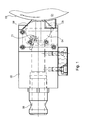
- the (not shown) (at least one) short inking unit comprises a roller 01 transferring printing ink, cf. Fig. 1 , which may be formed as a possibly tempered anilox roller 01, on which by means of a doctor blade 02 defining doctor blade 02 ink is auftagbar.
- the applied to the anilox roller 01 ink is then transferred in a manner not shown and known manner over other rollers such as ink rollers, friction rollers and inking rollers on a plate cylinder having one or more printing plates for the waterless planographic printing on its periphery.
- a plurality of doctor bar 02 or chamber doctor blades 02 can be arranged next to each other.
- the arrow C indicates the direction of rotation of the anilox roller 01.
- the doctor bar 02 is aligned parallel to the axis of the anilox roller 01 and movable between a functional position in which it is employed on the roller 01, and a rest position in which it is parked by the roller 01, for example, pivoted.
- a functional position in which it is employed on the roller 01 and a rest position in which it is parked by the roller 01, for example, pivoted.
- functional position of the squeegee bar 02 on the circumference 03 or surface 03 of the anilox roller 01 at.
- this functional position of the squeegee bar 02 this is for example pneumatically employed with a suitable overpressure against a fixed stop, not shown, so that it occupies a defined fixed position relative to the anilox roller 01.
- the doctor bar 02 has an ink chamber 04 for receiving ink, which is supplied to the ink chamber 04, for example, from a not shown, arranged below the squeegee 02 ink fountain with integrated paint pump.
- the ink chamber 04 is for this purpose at least one, preferably two ink inlets 06 connected, preferably at the two end portions of the ink chamber 04 z. B. in the form of a respective hole 06 in this open.
- at least one, in the case of the illustrated and described embodiment exactly an ink discharge 07 is provided, which preferably centrally, ie halfway along the ink chamber 04, z. B. also in the form of a hole 07, opens into this and a drainage of ink in the arranged below, not shown color box allows.
- the printing ink chamber 04 is open on the side facing the anilox roller 01, so that the surface 03 of the anilox roller 01 moving past the employed doctor blade 02 is inked with printing ink.
- the ink chamber 04 is seen in the direction of rotation C of the anilox roller 01 provided at the leading end and at the trailing end with a squeegee 08 and 09, namely with a work doctor blade 08 which rests at an obtuse angle to the surface 03 of the anilox roller 01 and a Squeegee 09 which sealingly abuts the surface 03 of the anilox roller 01 at an acute angle.
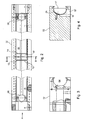
- the ink chamber 04 is completed by a side plate 11, see. Fig. 5 .
- squeegee bar 02 defined within the squeegee 02 02 ink chamber is thus completed laterally by the side plates 11 and top and bottom by the working doctor blade 08 and the squeegee 09.
- the ink chamber 04 is filled by means of the ink pump not shown on the ink feeds 06 under predetermined pressure with ink, the along the ink chamber 04 flowing ink colors the surface 03 of the anilox roller 01 and excess ink on the inks Run-off 07 from the ink chamber 04 runs into the ink fountain underneath.
- a deflection device 12 is arranged in the area of the ink outlet 07, namely adjacent between the respective ink inlet 06 and the ink outlet 07, in particular the ink sequence 06 arranged immediately adjacent to the ink drain 06.
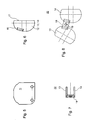
- the deflection device 12 may in particular comprise a deflecting plate 13 or 14, cf. Fig. 1 and 6 to 8 , In the case of the preferred embodiment with two end-side ink feeds 06 and a central ink discharge 07, it may, as shown, be advantageous, on both sides of the ink discharge 07 each a deflecting device 12 and a deflecting plate 13; 14 to provide.
- Each deflecting device 12 or deflecting plate 13; 14 includes a first side 16 and a first peripheral portion 16, whose shape corresponds to the inner cross section of the ink chamber 04 and over which it rests at least substantially sealingly against the inside of the ink chamber 04, and a second side 17 and a second Peripheral portion 17 which faces the anilox roller 01 and, for example, is rectilinear or, for example, may also be curved, for. B. according to the curvature of the surface 03 of the anilox roller 01 curved. As in particular from Fig.
- the second peripheral portion 17 is spaced from the surface 03 of the anilox roller 01, wherein the distance can be between 2 mm and 30 mm, in particular between 4 mm and 15 mm with an attached doctor beam 02, more preferably at about 8 mm, ie at 8 mm +/- 25%.
- the deflecting plate 13 and the deflecting plate 14 as a single, in cross-section U-shaped member 22 can be fastened, for example via a Through hole 19 for receiving a screwed into the doctor bar 02 mounting screw 21.
- the base 18 may be connected to the deflection signs 13; 14 be secured by laser welding, for example.
- the U-shaped component 22 is thus mounted in the ink chamber and the base 18 is designed so that in the mounted state, the two deflecting plates 13; 14 are located directly next to the ink outlet 07.
- the distance of the anilox roller 01 opposite side 17 of the deflector 12 and the deflecting plate 13 and 14 is formed adjustable, including the deflecting plate 13 and 14 z. B. may be slidably mounted in the housing of the doctor blade 02 and may optionally be adjustable from the outside by means of a screw, z. B. depending on the viscosity or temperature of the ink. If necessary, the setting can also be made automatically as a function of a suitable manipulated variable.
Description
Die Erfindung betrifft eine Einrichtung zum Einfärben einer Druckfarbe übertragenden Walze einer Rotationsdruckmaschine gemäß den Merkmalen des Anspruchs 1.The invention relates to a device for coloring an ink-transferring roller of a rotary printing press according to the features of claim 1.
Insbesondere bezieht sich die Erfindung auf ein Rakelsystem für ein Kurzfarbwerk mit hochviskosen Farben, wie sie z. B. im Wasserlosdruck eingesetzt werden, also bei einem wasserlosen Druckverfahren (z. B. mittels wasserloser Flachdruckplatte), insbesondere im "Trockenoffset" bzw. "wasserlosen Offsetdruck".In particular, the invention relates to a doctor blade system for a short inking unit with high-viscosity colors, as z. B. in waterless printing, ie in a waterless printing process (eg., By means of waterless planographic printing plate), especially in the "dry offset" or "waterless offset printing".
Aus der
Im Bereich des Ablaufes bilden sich jedoch aufgrund der Sogwirkung des abströmenden Mediums Wirbel und dergleichen, die zu erheblichen Farbdichteunterschieden im Druckprodukt führen können, die sich beispielsweise in einer Breite bis zu 80 mm in der Papierbahnmitte erstrecken können und somit in hohem Maße unerwünscht sind.In the region of the sequence, however, due to the suction effect of the outflowing medium, vortices and the like form, which can lead to considerable color density differences in the printed product, which can extend, for example, in a width of up to 80 mm in the middle of the paper web and are thus highly undesirable.
Die
Der Erfindung liegt die Aufgabe zugrunde, eine Einrichtung zum Einfärben einer Druckfarbe übertragenden Walze einer Rotationsdruckmaschine zu schaffen, womit in konstruktiv einfacher Weise die Qualität des Druckprodukts verbessert werden kann.The invention is based on the object, a device for coloring a To provide ink transfer roller of a rotary printing machine, which in a structurally simple way, the quality of the printed product can be improved.
Die Aufgabe wird erfindungsgemäß durch die Merkmale des Anspruchs 1 gelöst.The object is achieved by the features of claim 1.
Die mit der Erfindung erzielbaren Vorteile bestehen insbesondere darin, dass in konstruktiv einfacher Weise die Qualität des Druckprodukts verbessert werden kann. Insbesondere können die vorhandenen starken Farbdichteunterschiede im Bereich des Druckfarben-Ablaufs vermieden werden, indem die von der einzufärbenden Walze beabstandete Unlenkeinrichtung, in Form eines Umlenk-Schildes, die Druckfarbe zwingt, zwischen Umlenk-Schild und Walzenoberfläche vorbei an der Walzenoberfläche zu strömen, bevor sie die Druckfarbenkammer über den Druckfarben-Ablauf verlässt. Auf diese Weise können Farbdichteunterschiede in Axialrichtung der Walze vermieden oder doch zumindest erheblich reduziert werden.The advantages that can be achieved with the invention are, in particular, that the quality of the printed product can be improved in a structurally simple manner. In particular, the existing strong ink density differences in the area of the ink run can be avoided by the spaced apart from the inking roller deflector, in the form of a deflector shield, the ink forced to flow between the deflector blade and roll surface past the roll surface before they leaves the ink chamber through the ink drain. In this way color density differences in the axial direction of the roller can be avoided or at least considerably reduced.
Ausführungsbeispiele der Erfindung sind in den Zeichnungen dargestellt und werden im Folgenden näher beschrieben.Embodiments of the invention are illustrated in the drawings and will be described in more detail below.
- Fig. 1Fig. 1
- eine Seitenansicht eines an eine Walze angestellten, mit einer Umlenkeinrichtung ausgestatteten Rakelbalkens;a side view of an employee employed on a roller, equipped with a deflector squeegee bar;
- Fig. 2Fig. 2
-
eine Vorderansicht des Rakelbalkens nach
Fig. 1 ;a front view of the doctor blade afterFig. 1 ; - Fig. 3Fig. 3
-
eine Seitenansicht des Rakelbalkens nach
Fig. 2 in Richtung des Pfeils A;a side view of the doctor beam afterFig. 2 in the direction of arrow A; - Fig. 4Fig. 4
-
eine Schnittansicht des Rakelbalkens nach
Fig. 2 in der Ebene B - B;a sectional view of the doctor blade afterFig. 2 in the plane B - B; - Fig. 5Fig. 5
- eine Seitenansicht eines Seitenschilds des Rakelbalkens;a side view of a side plate of the doctor blade;
- Fig. 6Fig. 6
-
eine Seitenansicht eines U-förmigen Umlenkschild-Bauteils des Rakelbalkens nach
Fig. 1 bis 4 ;a side view of a U-shaped Umlenkschild component of the doctor blade according toFig. 1 to 4 ; - Fig. 7Fig. 7
-
eine Ansicht des Bauteils nach
Fig. 6 in einer hierzu senkrechten Ansicht;a view of the component afterFig. 6 in a view perpendicular thereto; - Fig. 8Fig. 8
-
eine Draufsicht auf das Bauteil nach
Fig. 7 und 8 im entfalteten Zustand der beiden Umlenkschilder.a plan view of the component according toFIGS. 7 and 8 in the unfolded state of the two deflection plates.
In einer im Übrigen nicht näher dargestellten Rollenrotationsdruckmaschine, beispielsweise für den Zeitungsdruck, insbesondere in einer Druckmaschine für den wasserlosen Offsetdruck, in deren Druckwerken bzw. Farbwerken kein Feuchtmittel verwendet wird, ist (mindestens) ein im Übrigen ebenfalls nicht näher dargestelltes Kurzfarbwerk vorgesehen, welches mit vorzugsweise hochviskosen Druckfarben arbeitet.In an otherwise not shown web-fed rotary printing press, for example, for newspaper printing, especially in a printing machine for waterless offset printing, in the printing units or inking no dampening solution is used (at least) incidentally also not shown in detail short inking unit is provided with preferably high viscosity inks works.
Im wasserlosen Offsetdruck übernimmt z. B eine Silikonschicht auf der Mantelfläche einer Druckform die Rolle des mit Feuchtmittel belegbaren hydrophilen Bereichs des "Nassoffset", um die Druckform an einer Farbaufnahme zu hindern. Allgemein werden die nicht-druckenden Bereiche und die druckenden Bereiche der Druckform durch die Ausbildung von Bereichen unterschiedlicher Oberflächenspannungen bei Wechselwirkung mit der Druckfarbe erreicht. Deshalb werden in wasserlosen Offsetdruckverfahren Druckfarben verwendet, deren Eigenschaften sich von Druckfarben unterscheiden, die im konventionellen "Nassoffset" verwendet werden, insbesondere werden Druckfarben verwendet, die eine höhere Viskosität aufweisen.In waterless offset printing z. B is a silicone layer on the lateral surface of a printing form the role of the wettable hydrophilic area of the "wet offset" to prevent the printing form on a color image. Generally, the non-printing areas and the printing areas of the printing form are achieved by the formation of areas of different surface tensions when interacting with the ink. Therefore, in waterless offset printing processes printing inks are used whose properties differ from printing inks used in conventional "wet offset", in particular printing inks are used which have a higher viscosity.
Die Viskosität der Druckfarbe wird z. B nach der Norm ISO 12644:1996(E) ermittelt. Die Viskosität ist eine von der Temperatur stark abhängige Messgröße. Mit zunehmender Temperatur zeigen Druckfarben in dem für den Druckprozess relevanten Temperaturbereich zwischen 15°C und 50°C, insbesondere zwischen 22°C und 40°C, einen deutlichen Abfall ihrer Viskosität. Der Wert der Viskosität liegt für geeignete Druckfarben im Temperaturbereich zwischen 22°C und 40°C, vorzugsweise von 27°C, unter 350 Pa*s, insbesondere zwischen 10 Pa*s und 150 Pa*s.The viscosity of the ink is z. B according to the standard ISO 12644: 1996 (E). The viscosity is a highly dependent on the temperature variable. With increasing temperature, printing inks show the pressure relevant to the printing process Temperature range between 15 ° C and 50 ° C, especially between 22 ° C and 40 ° C, a significant drop in their viscosity. The value of the viscosity for suitable printing inks in the temperature range between 22 ° C and 40 ° C, preferably of 27 ° C, below 350 Pa * s, in particular between 10 Pa * s and 150 Pa * s.
Das im Übrigen nicht näher dargestellte (mindestens eine) Kurzfarbwerk umfasst eine Druckfarben übertragende Walze 01, vgl.
Der Rakelbalken 02 ist parallel zur Achse der Rasterwalze 01 ausgerichtet und zwischen einer Funktionsstellung, in der er an die Walze 01 angestellt ist, und einer Ruhestellung, in der er von der Walze 01 abgestellt, beispielsweise abgeschwenkt ist, bewegbar. In der in
Der Rakelbalken 02 weist eine Druckfarben-Kammer 04 zur Aufnahme von Druckfarbe auf, die der Druckfarben-Kammer 04 beispielsweise von einem nicht näher dargestellten, unterhalb des Rakelbalkens 02 angeordneten Farbkasten mit integrierter Farbpumpe zugeführt wird. Die Druckfarben-Kammer 04 ist zu diesem Zweck mit mindestens einem, vorzugsweise zwei Druckfarben-Zuläufen 06 verbunden, die vorzugsweise an den beiden Endbereichen der Druckfarben-Kammer 04 z. B. in Form jeweils einer Bohrung 06 in diese münden. Des Weiteren ist mindestens ein, im Falle der dargestellten und beschriebenen Ausführungsform genau ein Druckfarben-Ablauf 07 vorgesehen, welcher vorzugsweise mittig, d. h. auf halber Länge der Druckfarben-Kammer 04, z. B. ebenfalls in Form einer Bohrung 07, in diese mündet und ein Abfließen von Druckfarbe in den unterhalb angeordneten, nicht näher dargestellten Farbkasten ermöglicht.The
Die Druckfarben-Kammer 04 ist auf der der Rasterwalze 01 zugewandten Seite offen, so dass die sich am angestellten Rakelbalken 02 vorbeibewegende Oberfläche 03 der Rasterwalze 01 mit Druckfarbe eingefärbt wird. Die Druckfarben-Kammer 04 ist in Rotationsrichtung C der Rasterwalze 01 gesehen am vorlaufenden Ende und am nachlaufenden Ende mit einer Rakel 08 bzw. 09 versehen, nämlich mit einer Arbeitsrakel 08, der unter einem stumpfen Winkel an der Oberfläche 03 der Rasterwalze 01 anliegt und einer Schließrakel 09, die unter spitzem Winkel an der Oberfläche 03 der Rasterwalze 01 dichtend anliegt.The
Seitlich ist die Druckfarben-Kammer 04 jeweils durch ein Seitenschild 11 abgeschlossen, vgl.
Um die im Bereich des Druckfarben-Ablaufs 07 ggf. auftretenden, eingangs erläuterten Farbdichte-Störungen zu vermeiden bzw. doch zumindest erheblich zu reduzieren, ist im Bereich des Druckfarben-Ablaufs 07 eine Umlenkeinrichtung 12 angeordnet, nämlich zwischen dem jeweiligen Druckfarben-Zulauf 06 und dem Druckfarben-Ablauf 07, insbesondere dem Druckfarben-Ablauf 06 benachbart, vorzugsweise unmittelbar neben dem Druckfarben-Ablauf 06 angeordnet.To those in the area of the
Die Umlenkeinrichtung 12 kann insbesondere ein Umlenk-Schild 13 bzw. 14 umfassen, vgl.
Jede Umlenkeinrichtung 12 bzw. jedes Umlenkschild 13; 14 umfasst eine erste Seite 16 bzw. einen ersten Umfangsabschnitt 16, dessen Form dem Innenquerschnitt der Druckfarben-Kammer 04 entspricht und über den er zumindest im Wesentlichen dichtend an der Innenseite der Druckfarben-Kammer 04 anliegt, sowie eine zweite Seite 17 bzw. einen zweiten Umfangsabschnitt 17, der der Rasterwalze 01 zugewandt ist und beispielsweise geradlinig ausgebildet ist oder beispielsweise auch gekrümmt sein kann, z. B. entsprechend der Krümmung der Oberfläche 03 der Rasterwalze 01 gekrümmt. Wie insbesondere auch aus
Auf diese Weise wird die über den Druckfarben-Ablauf 07 abfließende Druckfarbe gezwungen, über das Umlenk-Schild 13; 14 und vorbei an dem gegenüberliegenden Abschnitt der Oberfläche 03 der Rasterwalze 01 zu strömen, wodurch in diesem Bereich eine verbesserte Farbdichte erzielt werden kann.In this way, the effluent via the
Gemäß einer bevorzugten Ausführungsform sind das Umlenk-Schild 13 und das Umlenk-Schild 14 als ein einziges, im Querschnitt U-förmiges Bauteil 22 (vgl. insbesondere.
Gemäß einer weiteren, nicht näher dargestellten Ausführungsform der Erfindung ist der Abstand der der Rasterwalze 01 gegenüberliegenden Seite 17 der Umlenkeinrichtung 12 bzw. des Umlenk-Schilds 13 bzw. 14 einstellbar ausgebildet, wozu das Umlenk-Schild 13 bzw. 14 z. B. im Gehäuse des Rakelbalkens 02 verschieblich gelagert sein kann und ggf. von außen mittels einer Stellschraube einstellbar sein kann, z. B. je nach Viskosität oder Temperatur der Druckfarbe. Die Einstellung kann ggf. auch automatisch in Abhängigkeit von einer geeigneten Stellgröße erfolgen.According to a further, not shown embodiment of the invention, the distance of the
Bezugszeichenliste
- 01
- Walze, Rasterwalze
- 02
- Rakelbalken, Kammerrakel
- 03
- Umfang, Oberfläche (01)
- 04
- Druckfarben-Kammer
- 05
- -
- 06
- Druckfarben-Zulauf, Bohrung
- 07
- Druckfarben-Ablauf, Bohrung
- 08
- Rakel, Arbeitsrakel
- 09
- Rakel, Schließrakel
- 10
- -
- 11
- Seitenschild
- 12
- Umlenkeinrichtung
- 13
- Umlenk-Schild
- 14
- Umlenk-Schild
- 15
- -
- 16
- Seite, Umfangsabschnitt
- 17
- Seite, Umfangsabschnitt
- 18
- Basis
- 19
- Durchgangsbohrung
- 20
- -
- 21
- Befestigungsschraube
- 22
- Bauteil, U-förmig
- C
- Rotationsrichtung
- 01
- Roller, anilox roller
- 02
- Doctor blade, chambered doctor blade
- 03
- Circumference, surface (01)
- 04
- Ink chamber
- 05
- -
- 06
- Inlet ink inlet, bore
- 07
- Printing ink drain, bore
- 08
- Squeegee, work squeegee
- 09
- Squeegee, closing squeegee
- 10
- -
- 11
- side shield
- 12
- deflecting
- 13
- Deflecting shield
- 14
- Deflecting shield
- 15
- -
- 16
- Side, peripheral section
- 17
- Side, peripheral section
- 18
- Base
- 19
- Through Hole
- 20
- -
- 21
- fixing screw
- 22
- Component, U-shaped
- C
- direction of rotation
Claims (18)
- Device for inking a roll (01), which transfers printing ink, of a rotary printing press which has at least one doctor bar (02) which can be set against the roll (01) and defines a printing-ink chamber (04) which extends along the doctor bar (02), is open towards the roll (01) and is connected to at least one printing-ink inlet (06) and at least one printing-ink outlet (07), at least one deflecting device (12) which deflects printing ink in the direction of the roll (01) being arranged in the printing-ink chamber (04) between the at least one printing-ink inlet (06) and the at least one printing-ink outlet (07), the side (17) of which deflecting device (12), which side (17) faces the roll (01), is spaced apart from the roll (01) in the thrown-on state of the doctor bar (02), in each case one deflecting device (12) which is configured as a deflecting plate (13; 14) being arranged adjacently on both sides of the printing-ink outlet (07), characterized in that the deflecting plates (13; 14) are each arranged perpendicularly with respect to the axis of the roll (01).
- Device according to Claim 1, characterized in that the deflecting device (12) is arranged immediately next to the printing-ink outlet (07).
- Device according to one of the preceding claims, characterized in that the printing-ink chamber (04) is connected to two printing-ink inlets (06) which are in each case arranged at an end of the printing-ink chamber (04).
- Device according to Claim 3, characterized in that a printing-ink outlet (07) is arranged between the two printing-ink inlets (06).
- Device according to Claim 4, characterized in that the printing-ink outlet (07) is arranged centrally between the two printing-ink inlets (06).
- Device according to one of the preceding claims, characterized in that the printing-ink outlet (07) is defined by a hole (07) which opens into the printing-ink chamber (04).
- Device according to Claim 1, characterized in that a component (22) of U-shaped cross section is arranged in the printing-ink chamber (04) in the region of the printing-ink outlet (07), which component (22) defines in each case one deflecting plate (13; 14) on both sides of the printing-ink outlet (07).
- Device according to Claim 7, characterized in that the U-shaped component (22) is fixed via its base (18) in the printing-ink chamber (04).
- Device according to Claim 8, characterized in that the base (18) has at least one through hole (19) for fastening in the printing-ink chamber (04).
- Device according to one of the preceding claims, characterized in that the spacing of the side (17) of the deflecting device (12) from the roll (01), which side (17) faces the roll (01) and is spaced apart from the latter, lies between 2 mm and 30 mm in the thrown-on state of the doctor bar (02).
- Device according to Claim 10, characterized in that the spacing lies between 4 mm and 15 mm.
- Device according to Claim 11, characterized in that the spacing is 8 mm +/- 25%.
- Device according to one of the preceding claims, characterized in that the spacing of the side (17) of the deflecting device (12) from the roll (01), which side (17) faces the roll (01) and is spaced apart from the latter, is configured such that it can be adjusted.
- Device according to one of the preceding claims, characterized in that the deflecting device (12) bears with its circumferential section (16) which does not face the roll (01) against the wall of the printing-ink chamber (04).
- Device according to one of the preceding claims, characterized in that the rotary printing press operates using offset printing.
- Device according to one of the preceding claims, characterized in that the rotary printing press operates using waterless offset printing.
- Device according to one of the preceding claims, characterized in that the roll (01) to be inked is a roll (01) of a short inking unit.
- Device according to one of the preceding claims, characterized in that the roll (01) to be inked is an engraved roll (01).
Applications Claiming Priority (1)
| Application Number | Priority Date | Filing Date | Title |
|---|---|---|---|
| DE200710000812 DE102007000812A1 (en) | 2007-10-02 | 2007-10-02 | Device for inking an ink-transferring roller of a rotary printing machine and a doctor bar |
Publications (3)
| Publication Number | Publication Date |
|---|---|
| EP2045077A2 EP2045077A2 (en) | 2009-04-08 |
| EP2045077A3 EP2045077A3 (en) | 2011-11-30 |
| EP2045077B1 true EP2045077B1 (en) | 2012-09-12 |
Family
ID=40134787
Family Applications (1)
| Application Number | Title | Priority Date | Filing Date |
|---|---|---|---|
| EP20080164413 Active EP2045077B1 (en) | 2007-10-02 | 2008-09-16 | Equipment for inking an inking roller of a rotary printing press |
Country Status (2)
| Country | Link |
|---|---|
| EP (1) | EP2045077B1 (en) |
| DE (1) | DE102007000812A1 (en) |
Families Citing this family (1)
| Publication number | Priority date | Publication date | Assignee | Title |
|---|---|---|---|---|
| CN112918092B (en) * | 2021-02-05 | 2022-11-11 | 明光市瑞洁日用品有限公司 | Textile printing device |
Family Cites Families (7)
| Publication number | Priority date | Publication date | Assignee | Title |
|---|---|---|---|---|
| US2018193A (en) * | 1931-08-27 | 1935-10-22 | Goss Printing Press Co Ltd | Inking mechanism and method |
| DE3704433A1 (en) * | 1987-02-12 | 1988-08-25 | Frankenthal Ag Albert | SHORT COLOR PLANT |
| DE4117390C2 (en) * | 1991-05-28 | 2003-11-06 | Koenig & Bauer Ag | Squeegee bar for an inking unit of a rotary printing press |
| DE4138807C1 (en) * | 1991-11-26 | 1993-06-03 | Cornelis Wapenveld Nl Gorter | Colour chamber doctor - is for colour-transfer, screened circular cylindrical body such as screen roller or engraved cylinder |
| DE4401299C2 (en) * | 1994-01-18 | 1997-04-30 | Roland Man Druckmasch | Device for inking an anilox roller of a rotary printing press |
| US5531161A (en) * | 1994-12-07 | 1996-07-02 | Eastman Kodak Company | Gravure coating feeder apparatus |
| DE10158157B4 (en) | 2001-11-28 | 2006-09-07 | Koenig & Bauer Ag | Inking unit of a printing press |
-
2007
- 2007-10-02 DE DE200710000812 patent/DE102007000812A1/en not_active Withdrawn
-
2008
- 2008-09-16 EP EP20080164413 patent/EP2045077B1/en active Active
Also Published As
| Publication number | Publication date |
|---|---|
| EP2045077A3 (en) | 2011-11-30 |
| EP2045077A2 (en) | 2009-04-08 |
| DE102007000812A1 (en) | 2009-04-09 |
Similar Documents
| Publication | Publication Date | Title |
|---|---|---|
| DE3704433C2 (en) | ||
| DE3112745C2 (en) | Roller head that can be adjusted to a plate cylinder of an offset or letterpress machine | |
| EP2736723B1 (en) | Plate cylinder | |
| WO2011051072A1 (en) | Pressure setting device of a chambered doctor blade system | |
| CH654253A5 (en) | PRINT CYLINDER FOR AN ARC ROTATION PRINTING MACHINE. | |
| EP0111141B1 (en) | Ink fountain divider for rotary printing presses | |
| EP0663293A1 (en) | Device for inking an engraved roll | |
| DE10040519A1 (en) | Sheet guide device for card sheet printing press, with second cylinder in form of ink application or tool cylinder | |
| EP1467865B1 (en) | Device for inking a roller | |
| EP2045077B1 (en) | Equipment for inking an inking roller of a rotary printing press | |
| DE102007041756B4 (en) | ink chamber | |
| DE19942617A1 (en) | Device and method for performing a flying plate change | |
| EP1603750B1 (en) | Printing group of a printing unit, consisting of two printing groups which are placed vertically above each other, in a printing machine and printing unit | |
| EP1092539A1 (en) | Arrangement for sealing an ink conveying reservoir in printing machines | |
| DE102006035504A1 (en) | Printing unit of a web-fed rotary printing machine | |
| EP1534522B1 (en) | Rotary press inking units | |
| DE10103631A1 (en) | Rotary press | |
| EP0657282B1 (en) | Inking device | |
| DE102009001083A1 (en) | Printing or inking unit | |
| DE10232254B4 (en) | Rotary screen printing machine | |
| DE19949346A1 (en) | Inker unit seal for printer has ink-store, tank, side surfaces, elastic element, gap, contact surfaces | |
| DE102008042263B4 (en) | Apparatus for applying printing ink | |
| DE102006035290B4 (en) | Device for inking a printing ink-transferring roller of a web-fed rotary printing machine | |
| DE10303608B4 (en) | Method for a stable machine run on printing units of a rotary printing press for operation with partially wide printing material | |
| DE202022107008U1 (en) | Automatic and unidirectionally adjustable chamber doctor blade |
Legal Events
| Date | Code | Title | Description |
|---|---|---|---|
| PUAI | Public reference made under article 153(3) epc to a published international application that has entered the european phase |
Free format text: ORIGINAL CODE: 0009012 |
|
| AK | Designated contracting states |
Kind code of ref document: A2 Designated state(s): AT BE BG CH CY CZ DE DK EE ES FI FR GB GR HR HU IE IS IT LI LT LU LV MC MT NL NO PL PT RO SE SI SK TR |
|
| AX | Request for extension of the european patent |
Extension state: AL BA MK RS |
|
| PUAL | Search report despatched |
Free format text: ORIGINAL CODE: 0009013 |
|
| AK | Designated contracting states |
Kind code of ref document: A3 Designated state(s): AT BE BG CH CY CZ DE DK EE ES FI FR GB GR HR HU IE IS IT LI LT LU LV MC MT NL NO PL PT RO SE SI SK TR |
|
| AX | Request for extension of the european patent |
Extension state: AL BA MK RS |
|
| RIC1 | Information provided on ipc code assigned before grant |
Ipc: B41F 31/02 20060101AFI20111024BHEP |
|
| 17P | Request for examination filed |
Effective date: 20111122 |
|
| GRAP | Despatch of communication of intention to grant a patent |
Free format text: ORIGINAL CODE: EPIDOSNIGR1 |
|
| RTI1 | Title (correction) |
Free format text: EQUIPMENT FOR INKING AN INKING ROLLER OF A ROTARY PRINTING PRESS |
|
| GRAS | Grant fee paid |
Free format text: ORIGINAL CODE: EPIDOSNIGR3 |
|
| AKX | Designation fees paid |
Designated state(s): AT BE BG CH CY CZ DE DK EE ES FI FR GB GR HR HU IE IS IT LI LT LU LV MC MT NL NO PL PT RO SE SI SK TR |
|
| GRAA | (expected) grant |
Free format text: ORIGINAL CODE: 0009210 |
|
| AK | Designated contracting states |
Kind code of ref document: B1 Designated state(s): AT BE BG CH CY CZ DE DK EE ES FI FR GB GR HR HU IE IS IT LI LT LU LV MC MT NL NO PL PT RO SE SI SK TR |
|
| REG | Reference to a national code |
Ref country code: GB Ref legal event code: FG4D Free format text: NOT ENGLISH |
|
| REG | Reference to a national code |
Ref country code: CH Ref legal event code: EP |
|
| REG | Reference to a national code |
Ref country code: AT Ref legal event code: REF Ref document number: 574854 Country of ref document: AT Kind code of ref document: T Effective date: 20120915 |
|
| REG | Reference to a national code |
Ref country code: IE Ref legal event code: FG4D Free format text: LANGUAGE OF EP DOCUMENT: GERMAN |
|
| REG | Reference to a national code |
Ref country code: DE Ref legal event code: R096 Ref document number: 502008008157 Country of ref document: DE Effective date: 20121108 |
|
| PG25 | Lapsed in a contracting state [announced via postgrant information from national office to epo] |
Ref country code: FI Free format text: LAPSE BECAUSE OF FAILURE TO SUBMIT A TRANSLATION OF THE DESCRIPTION OR TO PAY THE FEE WITHIN THE PRESCRIBED TIME-LIMIT Effective date: 20120912 Ref country code: CY Free format text: LAPSE BECAUSE OF FAILURE TO SUBMIT A TRANSLATION OF THE DESCRIPTION OR TO PAY THE FEE WITHIN THE PRESCRIBED TIME-LIMIT Effective date: 20120912 Ref country code: NO Free format text: LAPSE BECAUSE OF FAILURE TO SUBMIT A TRANSLATION OF THE DESCRIPTION OR TO PAY THE FEE WITHIN THE PRESCRIBED TIME-LIMIT Effective date: 20121212 Ref country code: LT Free format text: LAPSE BECAUSE OF FAILURE TO SUBMIT A TRANSLATION OF THE DESCRIPTION OR TO PAY THE FEE WITHIN THE PRESCRIBED TIME-LIMIT Effective date: 20120912 Ref country code: HR Free format text: LAPSE BECAUSE OF FAILURE TO SUBMIT A TRANSLATION OF THE DESCRIPTION OR TO PAY THE FEE WITHIN THE PRESCRIBED TIME-LIMIT Effective date: 20120912 |
|
| PGFP | Annual fee paid to national office [announced via postgrant information from national office to epo] |
Ref country code: CH Payment date: 20121001 Year of fee payment: 5 |
|
| REG | Reference to a national code |
Ref country code: NL Ref legal event code: VDEP Effective date: 20120912 |
|
| REG | Reference to a national code |
Ref country code: LT Ref legal event code: MG4D Effective date: 20120912 |
|
| PG25 | Lapsed in a contracting state [announced via postgrant information from national office to epo] |
Ref country code: LV Free format text: LAPSE BECAUSE OF FAILURE TO SUBMIT A TRANSLATION OF THE DESCRIPTION OR TO PAY THE FEE WITHIN THE PRESCRIBED TIME-LIMIT Effective date: 20120912 Ref country code: SE Free format text: LAPSE BECAUSE OF FAILURE TO SUBMIT A TRANSLATION OF THE DESCRIPTION OR TO PAY THE FEE WITHIN THE PRESCRIBED TIME-LIMIT Effective date: 20120912 Ref country code: SI Free format text: LAPSE BECAUSE OF FAILURE TO SUBMIT A TRANSLATION OF THE DESCRIPTION OR TO PAY THE FEE WITHIN THE PRESCRIBED TIME-LIMIT Effective date: 20120912 Ref country code: GR Free format text: LAPSE BECAUSE OF FAILURE TO SUBMIT A TRANSLATION OF THE DESCRIPTION OR TO PAY THE FEE WITHIN THE PRESCRIBED TIME-LIMIT Effective date: 20121213 |
|
| PGFP | Annual fee paid to national office [announced via postgrant information from national office to epo] |
Ref country code: ES Payment date: 20120928 Year of fee payment: 5 |
|
| BERE | Be: lapsed |
Owner name: KOENIG & BAUER A.G. Effective date: 20120930 |
|
| PG25 | Lapsed in a contracting state [announced via postgrant information from national office to epo] |
Ref country code: CZ Free format text: LAPSE BECAUSE OF FAILURE TO SUBMIT A TRANSLATION OF THE DESCRIPTION OR TO PAY THE FEE WITHIN THE PRESCRIBED TIME-LIMIT Effective date: 20120912 Ref country code: IS Free format text: LAPSE BECAUSE OF FAILURE TO SUBMIT A TRANSLATION OF THE DESCRIPTION OR TO PAY THE FEE WITHIN THE PRESCRIBED TIME-LIMIT Effective date: 20130112 Ref country code: RO Free format text: LAPSE BECAUSE OF FAILURE TO SUBMIT A TRANSLATION OF THE DESCRIPTION OR TO PAY THE FEE WITHIN THE PRESCRIBED TIME-LIMIT Effective date: 20120912 Ref country code: NL Free format text: LAPSE BECAUSE OF FAILURE TO SUBMIT A TRANSLATION OF THE DESCRIPTION OR TO PAY THE FEE WITHIN THE PRESCRIBED TIME-LIMIT Effective date: 20120912 Ref country code: MC Free format text: LAPSE BECAUSE OF NON-PAYMENT OF DUE FEES Effective date: 20120930 Ref country code: EE Free format text: LAPSE BECAUSE OF FAILURE TO SUBMIT A TRANSLATION OF THE DESCRIPTION OR TO PAY THE FEE WITHIN THE PRESCRIBED TIME-LIMIT Effective date: 20120912 Ref country code: ES Free format text: LAPSE BECAUSE OF FAILURE TO SUBMIT A TRANSLATION OF THE DESCRIPTION OR TO PAY THE FEE WITHIN THE PRESCRIBED TIME-LIMIT Effective date: 20121223 |
|
| PG25 | Lapsed in a contracting state [announced via postgrant information from national office to epo] |
Ref country code: PT Free format text: LAPSE BECAUSE OF FAILURE TO SUBMIT A TRANSLATION OF THE DESCRIPTION OR TO PAY THE FEE WITHIN THE PRESCRIBED TIME-LIMIT Effective date: 20130114 Ref country code: SK Free format text: LAPSE BECAUSE OF FAILURE TO SUBMIT A TRANSLATION OF THE DESCRIPTION OR TO PAY THE FEE WITHIN THE PRESCRIBED TIME-LIMIT Effective date: 20120912 Ref country code: PL Free format text: LAPSE BECAUSE OF FAILURE TO SUBMIT A TRANSLATION OF THE DESCRIPTION OR TO PAY THE FEE WITHIN THE PRESCRIBED TIME-LIMIT Effective date: 20120912 |
|
| REG | Reference to a national code |
Ref country code: IE Ref legal event code: MM4A |
|
| PLBE | No opposition filed within time limit |
Free format text: ORIGINAL CODE: 0009261 |
|
| STAA | Information on the status of an ep patent application or granted ep patent |
Free format text: STATUS: NO OPPOSITION FILED WITHIN TIME LIMIT |
|
| PG25 | Lapsed in a contracting state [announced via postgrant information from national office to epo] |
Ref country code: DK Free format text: LAPSE BECAUSE OF FAILURE TO SUBMIT A TRANSLATION OF THE DESCRIPTION OR TO PAY THE FEE WITHIN THE PRESCRIBED TIME-LIMIT Effective date: 20120912 Ref country code: BG Free format text: LAPSE BECAUSE OF FAILURE TO SUBMIT A TRANSLATION OF THE DESCRIPTION OR TO PAY THE FEE WITHIN THE PRESCRIBED TIME-LIMIT Effective date: 20121212 Ref country code: IE Free format text: LAPSE BECAUSE OF NON-PAYMENT OF DUE FEES Effective date: 20120916 Ref country code: BE Free format text: LAPSE BECAUSE OF NON-PAYMENT OF DUE FEES Effective date: 20120930 |
|
| 26N | No opposition filed |
Effective date: 20130613 |
|
| REG | Reference to a national code |
Ref country code: DE Ref legal event code: R097 Ref document number: 502008008157 Country of ref document: DE Effective date: 20130613 |
|
| PG25 | Lapsed in a contracting state [announced via postgrant information from national office to epo] |
Ref country code: MT Free format text: LAPSE BECAUSE OF FAILURE TO SUBMIT A TRANSLATION OF THE DESCRIPTION OR TO PAY THE FEE WITHIN THE PRESCRIBED TIME-LIMIT Effective date: 20120912 |
|
| PG25 | Lapsed in a contracting state [announced via postgrant information from national office to epo] |
Ref country code: TR Free format text: LAPSE BECAUSE OF FAILURE TO SUBMIT A TRANSLATION OF THE DESCRIPTION OR TO PAY THE FEE WITHIN THE PRESCRIBED TIME-LIMIT Effective date: 20120912 |
|
| REG | Reference to a national code |
Ref country code: CH Ref legal event code: PL |
|
| PG25 | Lapsed in a contracting state [announced via postgrant information from national office to epo] |
Ref country code: LU Free format text: LAPSE BECAUSE OF NON-PAYMENT OF DUE FEES Effective date: 20120916 |
|
| PG25 | Lapsed in a contracting state [announced via postgrant information from national office to epo] |
Ref country code: CH Free format text: LAPSE BECAUSE OF NON-PAYMENT OF DUE FEES Effective date: 20130930 Ref country code: HU Free format text: LAPSE BECAUSE OF FAILURE TO SUBMIT A TRANSLATION OF THE DESCRIPTION OR TO PAY THE FEE WITHIN THE PRESCRIBED TIME-LIMIT Effective date: 20080916 Ref country code: LI Free format text: LAPSE BECAUSE OF NON-PAYMENT OF DUE FEES Effective date: 20130930 |
|
| REG | Reference to a national code |
Ref country code: AT Ref legal event code: MM01 Ref document number: 574854 Country of ref document: AT Kind code of ref document: T Effective date: 20130916 |
|
| PG25 | Lapsed in a contracting state [announced via postgrant information from national office to epo] |
Ref country code: AT Free format text: LAPSE BECAUSE OF NON-PAYMENT OF DUE FEES Effective date: 20130916 |
|
| REG | Reference to a national code |
Ref country code: DE Ref legal event code: R081 Ref document number: 502008008157 Country of ref document: DE Owner name: KOENIG BAUER AG, DE Free format text: FORMER OWNER: KOENIG BAUER AKTIENGESELLSCHAFT, 97080 WUERZBURG, DE Ref country code: DE Ref legal event code: R081 Ref document number: 502008008157 Country of ref document: DE Owner name: KOENIG & BAUER AG, DE Free format text: FORMER OWNER: KOENIG & BAUER AKTIENGESELLSCHAFT, 97080 WUERZBURG, DE |
|
| REG | Reference to a national code |
Ref country code: FR Ref legal event code: PLFP Year of fee payment: 9 |
|
| REG | Reference to a national code |
Ref country code: FR Ref legal event code: PLFP Year of fee payment: 10 |
|
| REG | Reference to a national code |
Ref country code: FR Ref legal event code: CA Effective date: 20170922 Ref country code: FR Ref legal event code: CD Owner name: KOENIG & BAUER AG, DE Effective date: 20170922 |
|
| REG | Reference to a national code |
Ref country code: FR Ref legal event code: PLFP Year of fee payment: 11 |
|
| PGFP | Annual fee paid to national office [announced via postgrant information from national office to epo] |
Ref country code: IT Payment date: 20180928 Year of fee payment: 11 |
|
| PG25 | Lapsed in a contracting state [announced via postgrant information from national office to epo] |
Ref country code: IT Free format text: LAPSE BECAUSE OF NON-PAYMENT OF DUE FEES Effective date: 20190916 |
|
| PGFP | Annual fee paid to national office [announced via postgrant information from national office to epo] |
Ref country code: GB Payment date: 20230920 Year of fee payment: 16 |
|
| PGFP | Annual fee paid to national office [announced via postgrant information from national office to epo] |
Ref country code: FR Payment date: 20230922 Year of fee payment: 16 Ref country code: DE Payment date: 20230905 Year of fee payment: 16 |