EP2045044A1 - Verfahren zum Zusammensetzen eines Federbeins und nach diesem Verfahren zusammengesetztes Federbein - Google Patents
Verfahren zum Zusammensetzen eines Federbeins und nach diesem Verfahren zusammengesetztes Federbein Download PDFInfo
- Publication number
- EP2045044A1 EP2045044A1 EP08165729A EP08165729A EP2045044A1 EP 2045044 A1 EP2045044 A1 EP 2045044A1 EP 08165729 A EP08165729 A EP 08165729A EP 08165729 A EP08165729 A EP 08165729A EP 2045044 A1 EP2045044 A1 EP 2045044A1
- Authority
- EP
- European Patent Office
- Prior art keywords
- suspension spring
- strut
- spring
- hook
- suspension
- Prior art date
- Legal status (The legal status is an assumption and is not a legal conclusion. Google has not performed a legal analysis and makes no representation as to the accuracy of the status listed.)
- Granted
Links
- 238000000034 method Methods 0.000 title claims abstract description 24
- 239000000725 suspension Substances 0.000 claims abstract description 69
- 239000006096 absorbing agent Substances 0.000 claims abstract description 7
- 230000035939 shock Effects 0.000 claims abstract description 7
- 239000002184 metal Substances 0.000 claims abstract description 3
- 239000000463 material Substances 0.000 claims description 3
- 230000006835 compression Effects 0.000 description 7
- 238000007906 compression Methods 0.000 description 7
- 101100536354 Drosophila melanogaster tant gene Proteins 0.000 description 2
- 230000000712 assembly Effects 0.000 description 2
- 238000000429 assembly Methods 0.000 description 2
- 239000000470 constituent Substances 0.000 description 1
- 238000010276 construction Methods 0.000 description 1
- 230000001627 detrimental effect Effects 0.000 description 1
- 238000009434 installation Methods 0.000 description 1
- 239000013067 intermediate product Substances 0.000 description 1
- 230000000284 resting effect Effects 0.000 description 1
- 238000011144 upstream manufacturing Methods 0.000 description 1
Images

Classifications
-
- B—PERFORMING OPERATIONS; TRANSPORTING
- B60—VEHICLES IN GENERAL
- B60G—VEHICLE SUSPENSION ARRANGEMENTS
- B60G15/00—Resilient suspensions characterised by arrangement, location or type of combined spring and vibration damper, e.g. telescopic type
- B60G15/02—Resilient suspensions characterised by arrangement, location or type of combined spring and vibration damper, e.g. telescopic type having mechanical spring
- B60G15/06—Resilient suspensions characterised by arrangement, location or type of combined spring and vibration damper, e.g. telescopic type having mechanical spring and fluid damper
- B60G15/062—Resilient suspensions characterised by arrangement, location or type of combined spring and vibration damper, e.g. telescopic type having mechanical spring and fluid damper the spring being arranged around the damper
- B60G15/063—Resilient suspensions characterised by arrangement, location or type of combined spring and vibration damper, e.g. telescopic type having mechanical spring and fluid damper the spring being arranged around the damper characterised by the mounting of the spring on the damper
-
- B—PERFORMING OPERATIONS; TRANSPORTING
- B25—HAND TOOLS; PORTABLE POWER-DRIVEN TOOLS; MANIPULATORS
- B25B—TOOLS OR BENCH DEVICES NOT OTHERWISE PROVIDED FOR, FOR FASTENING, CONNECTING, DISENGAGING OR HOLDING
- B25B27/00—Hand tools, specially adapted for fitting together or separating parts or objects whether or not involving some deformation, not otherwise provided for
- B25B27/14—Hand tools, specially adapted for fitting together or separating parts or objects whether or not involving some deformation, not otherwise provided for for assembling objects other than by press fit or detaching same
- B25B27/30—Hand tools, specially adapted for fitting together or separating parts or objects whether or not involving some deformation, not otherwise provided for for assembling objects other than by press fit or detaching same positioning or withdrawing springs, e.g. coil or leaf springs
- B25B27/302—Hand tools, specially adapted for fitting together or separating parts or objects whether or not involving some deformation, not otherwise provided for for assembling objects other than by press fit or detaching same positioning or withdrawing springs, e.g. coil or leaf springs coil springs other than torsion coil springs
- B25B27/304—Hand tools, specially adapted for fitting together or separating parts or objects whether or not involving some deformation, not otherwise provided for for assembling objects other than by press fit or detaching same positioning or withdrawing springs, e.g. coil or leaf springs coil springs other than torsion coil springs by compressing coil springs
-
- B—PERFORMING OPERATIONS; TRANSPORTING
- B60—VEHICLES IN GENERAL
- B60G—VEHICLE SUSPENSION ARRANGEMENTS
- B60G2206/00—Indexing codes related to the manufacturing of suspensions: constructional features, the materials used, procedures or tools
- B60G2206/01—Constructional features of suspension elements, e.g. arms, dampers, springs
- B60G2206/90—Maintenance
- B60G2206/91—Assembly procedures
-
- B—PERFORMING OPERATIONS; TRANSPORTING
- B60—VEHICLES IN GENERAL
- B60G—VEHICLE SUSPENSION ARRANGEMENTS
- B60G2206/00—Indexing codes related to the manufacturing of suspensions: constructional features, the materials used, procedures or tools
- B60G2206/01—Constructional features of suspension elements, e.g. arms, dampers, springs
- B60G2206/90—Maintenance
- B60G2206/92—Tools or equipment used for assembling
- B60G2206/921—Coil spring compressor
Definitions
- the present invention relates to a method of assembly or pre-assembly of strut.
- a strut consists of a shock absorber, a helical suspension spring, an upper support and a lower support for the suspension spring.
- the purpose of the present invention is to facilitate the assembly or pre-assembly of the strut, in particular by an automotive supplier.
- the object of the present invention also relates to the suspension spring as an intermediate supply and the strut obtained by said method.
- One method used according to the prior art to assemble a strut is as follows. First of all it is necessary to fix the shock absorber so that it remains stable when one applies a compressive force to it. Then the suspension spring is placed coaxially with the damper so that it rests on a lower cup integral with the damper. On the free end of the suspension spring is disposed a filter block having the upper support cup of the suspension spring. The assembly is then compressed so that the rod of the damper passes through the hole of the filter block. A nut is screwed onto the end of the damper rod in order to secure the suspension spring-filter block and damper assembly. Finally the compression force is released and the strut is then assembled in a relaxed position.
- the document US 4,442,580 proposes a tool in the form of articulated hook for locking a spring for disassembly and reassembly of the latter on a strut.
- This tool is intended more specifically for garages to intervene on any leg of force already mounted on a vehicle.
- This tool is therefore a general tool for a vehicle intervention already put into service.
- this tool is not suitable because its characteristics are not necessarily those required for the pre-assembly of a given leg.
- the articulation of the tool makes its use delicate. Indeed, the hook being hinged, the latter has a structural instability vis-à-vis the spring.
- Such a tool is not suitable for pre-assembly in series and in large numbers of a strut in an automotive equipment shop.
- the present invention proposes to provide a solution to the above problem by using, during assembly, a pre-compressed suspension spring to a length corresponding to the position of the relaxed strut.
- the proposed method for assembling a suspension strut comprising a damper, a suspension spring, a suspension spring upper support and a lower support for the suspension spring is articulated around the following successive steps. Firstly, the suspension spring is compressed before the assembly phase to a predetermined length and independently of the other components of the suspension strut. Then the suspension spring is kept compressed to this predetermined length by mechanical locking means in extension. Finally the strut is assembled, the suspension spring being kept compressed to this predetermined length.
- the compression of the suspension spring is independent and prior to the assembly of the strut. Indeed, the compression of the suspension spring is made upstream of the assembly of the strut. The means for maintaining the spring in pre-compression state is then posed. Only when the suspension spring is maintained in a state of pre-compression can the assembly of the strut be carried out.
- the holding means is adapted to maintain the compressed spring at a predetermined length. That is, the length of the holding means is adapted for a predetermined spring pattern to be mounted on a predetermined strut pattern. It is therefore understandable that for different models of spring and strut, the holding means are different, especially as regards their length.
- This method has the advantage of being able to do without press during the assembly of the strut.
- the suspension spring is pre-compressed beforehand, its adjustment on the strut vis-à-vis the support cups is also facilitated. In addition any risk of damage to the suspension spring during its compression during the assembly phase of the strut is also avoided. Finally, with this new method, it is also possible to assemble with much greater ease than before the force legs equipped with curved spring generators.
- the suspension spring can be kept compressed by means of at least one hook.
- Said at least one hook will be mounted between certain turns adjacent to its respective ends. Depending on the length of said hook and the relative position of the turns of said suspension spring, the compression length of the suspension spring can be easily adjusted.
- the present invention also includes the strut assembled by said method as an intermediate supply. Indeed, such a strut has, before installation on the vehicle, a suspension spring always compressed, although it is also kept blocked by the upper and lower support cups.
- the suspension spring maintained compressed by means of at least one hook for the construction of a strut by the method of the present invention is also part of the latter as an intermediate supply.
- a suspension spring packaged in this way has indeed a definite advantage in facilitating the assembly a leg, especially by allowing the assembler to do without heavy tools as a press.
- the length of the hook is adapted to maintain the spring compressed to a predetermined length so that for each type of spring (each length of spring) corresponds a type of hook (a length of hook) to mount the spring on a given leg .
- said hook will be metal or plastic. These materials are indeed common and easy to implement.
- suspension spring is advantageously maintained compressed to a length corresponding to the length of the suspension spring mounted on the strut when the latter is relaxed.
- the locking of the suspension spring is adjusted in the best possible way and the cooperation of the suspension spring in the strut during its commissioning will be optimal. This also facilitates the removal of the hook during the commissioning of the strut.
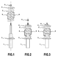
- a strut consists of a shock absorber 1, a suspension spring 2, a lower support cup 3 secured to the damper 1 and a filter block 4 subsequently called upper support and comprising among others a cup of superior support.
- the strut also includes a locking nut 5 for holding the assembly.
- the suspension spring 2 is held compressed at a certain length by at least one hook 6. Two hooks are shown in the figure.
- step 1 on the figure 1 , the spring 2 is placed coaxially with the damper 1 on the lower support 3 integral with the damper 1.
- the filter block 4 is then also placed coaxially with the damper 1, resting on the spring 2. The positioning of the spring assembly 2-filter block 4 is then adjusted.
- step 2 on the figure 2 , the nut 5 is screwed so as to abut with the filter block 4.
- the suspension spring 2 is supposed to be pre-compressed to a length such that the upper level of the spring assembly 2-filter block 4 is at the level of the thread of the rod of the damper 1.
- the stroke of the nut is not limited by the length of the thread of the rod of the damper and tightening conditions are easy.
- the nut 5 is then locked and the strut is finished to be assembled in step 3 on the figure 3 .
- this type of precaution can be considered for certain types of assemblies.
- the figure 3 represents a relaxed strut assembled according to the method of the present invention.
- the hooks still present show that the leg has not yet been put into service.
- the figure 4 represents a suspension spring maintained compressed in this example by two hooks.
- This suspension spring is an intermediate supply necessary for the mounting method of the present invention.
- the figure 5 represents a strut during its commissioning, that is to say undergoing a compressive force when the vehicle is on its wheels. In such a state, the figure 5 shows that it is then easy to deposit said at least one hook: the spring is compressed more and the hooks are easily released or fall to the ground.
Applications Claiming Priority (1)
| Application Number | Priority Date | Filing Date | Title |
|---|---|---|---|
| FR0758094A FR2921864B1 (fr) | 2007-10-05 | 2007-10-05 | Procede d'assemblage de jambe de force et jambe de force assemblee selon ce procede |
Publications (2)
| Publication Number | Publication Date |
|---|---|
| EP2045044A1 true EP2045044A1 (de) | 2009-04-08 |
| EP2045044B1 EP2045044B1 (de) | 2013-12-04 |
Family
ID=39361417
Family Applications (1)
| Application Number | Title | Priority Date | Filing Date |
|---|---|---|---|
| EP08165729.8A Active EP2045044B1 (de) | 2007-10-05 | 2008-10-02 | Verfahren zum Zusammensetzen eines Federbeins und nach diesem Verfahren zusammengesetztes Federbein |
Country Status (2)
| Country | Link |
|---|---|
| EP (1) | EP2045044B1 (de) |
| FR (1) | FR2921864B1 (de) |
Cited By (4)
| Publication number | Priority date | Publication date | Assignee | Title |
|---|---|---|---|---|
| DE102010010654A1 (de) | 2010-03-09 | 2011-09-15 | Dr. Ing. H.C. F. Porsche Aktiengesellschaft | Montagehilfe |
| EP2667049A3 (de) * | 2012-05-22 | 2016-01-06 | Muhr und Bender KG | Anordnung mit Schraubenfeder und Haltemitteln, Verwendung von Haltemitteln und Verfahren zur Montage von Schraubenfedern |
| CN108555832A (zh) * | 2018-05-29 | 2018-09-21 | 河南森源电气股份有限公司 | 弹簧压装架 |
| DE102020113706B3 (de) * | 2020-05-20 | 2021-04-29 | Dr. Ing. H.C. F. Porsche Aktiengesellschaft | Montagehilfe und Verfahren zur Montage und Demontage von Blockierelementen an einem Federbein |
Citations (8)
| Publication number | Priority date | Publication date | Assignee | Title |
|---|---|---|---|---|
| US3973314A (en) * | 1975-08-21 | 1976-08-10 | Shultz William E | Spring compression tool |
| FR2451805A1 (fr) * | 1979-03-23 | 1980-10-17 | Carlsson Carl | Outil manuel destine a comprimer des ressorts helicoidaux de compression |
| US4276684A (en) * | 1980-03-07 | 1981-07-07 | Mattson Charles T | Hand tool spring compressor |
| US4442580A (en) | 1981-04-03 | 1984-04-17 | Dimitrios Antoniadis | Coil spring tool |
| US4930751A (en) * | 1989-08-21 | 1990-06-05 | Hutchins Willie R | Coil spring compressing tool |
| USRE34097E (en) * | 1981-03-10 | 1992-10-13 | Spring compressor with latchable locking device | |
| FR2698818A1 (fr) * | 1992-12-08 | 1994-06-10 | Bompuis Gilles | Outillage pour le remplacement des amortisseurs de véhicules. |
| EP0925966A2 (de) * | 1997-11-19 | 1999-06-30 | Dr.Ing. h.c.F. Porsche Aktiengesellschaft | Vorrichtung zum Blockieren einer Feder in einem Federbein |
-
2007
- 2007-10-05 FR FR0758094A patent/FR2921864B1/fr active Active
-
2008
- 2008-10-02 EP EP08165729.8A patent/EP2045044B1/de active Active
Patent Citations (8)
| Publication number | Priority date | Publication date | Assignee | Title |
|---|---|---|---|---|
| US3973314A (en) * | 1975-08-21 | 1976-08-10 | Shultz William E | Spring compression tool |
| FR2451805A1 (fr) * | 1979-03-23 | 1980-10-17 | Carlsson Carl | Outil manuel destine a comprimer des ressorts helicoidaux de compression |
| US4276684A (en) * | 1980-03-07 | 1981-07-07 | Mattson Charles T | Hand tool spring compressor |
| USRE34097E (en) * | 1981-03-10 | 1992-10-13 | Spring compressor with latchable locking device | |
| US4442580A (en) | 1981-04-03 | 1984-04-17 | Dimitrios Antoniadis | Coil spring tool |
| US4930751A (en) * | 1989-08-21 | 1990-06-05 | Hutchins Willie R | Coil spring compressing tool |
| FR2698818A1 (fr) * | 1992-12-08 | 1994-06-10 | Bompuis Gilles | Outillage pour le remplacement des amortisseurs de véhicules. |
| EP0925966A2 (de) * | 1997-11-19 | 1999-06-30 | Dr.Ing. h.c.F. Porsche Aktiengesellschaft | Vorrichtung zum Blockieren einer Feder in einem Federbein |
Cited By (6)
| Publication number | Priority date | Publication date | Assignee | Title |
|---|---|---|---|---|
| DE102010010654A1 (de) | 2010-03-09 | 2011-09-15 | Dr. Ing. H.C. F. Porsche Aktiengesellschaft | Montagehilfe |
| US8590127B2 (en) | 2010-03-09 | 2013-11-26 | Dr. Ing. H.C. F. Porsche Aktiengesellschaft | Installation aid |
| DE102010010654B4 (de) | 2010-03-09 | 2019-01-31 | Dr. Ing. H.C. F. Porsche Aktiengesellschaft | Montagehilfe |
| EP2667049A3 (de) * | 2012-05-22 | 2016-01-06 | Muhr und Bender KG | Anordnung mit Schraubenfeder und Haltemitteln, Verwendung von Haltemitteln und Verfahren zur Montage von Schraubenfedern |
| CN108555832A (zh) * | 2018-05-29 | 2018-09-21 | 河南森源电气股份有限公司 | 弹簧压装架 |
| DE102020113706B3 (de) * | 2020-05-20 | 2021-04-29 | Dr. Ing. H.C. F. Porsche Aktiengesellschaft | Montagehilfe und Verfahren zur Montage und Demontage von Blockierelementen an einem Federbein |
Also Published As
| Publication number | Publication date |
|---|---|
| FR2921864B1 (fr) | 2017-03-10 |
| FR2921864A1 (fr) | 2009-04-10 |
| EP2045044B1 (de) | 2013-12-04 |
Similar Documents
| Publication | Publication Date | Title |
|---|---|---|
| EP2045044B1 (de) | Verfahren zum Zusammensetzen eines Federbeins und nach diesem Verfahren zusammengesetztes Federbein | |
| EP3626624B1 (de) | Montageverfahren von einem pylon eines flugzeugs | |
| EP2814640B1 (de) | Werkzeug zum montieren einer aufhängungs-blattfeder an den fahrzeugrahmen und den radträger einer fahrzeugachse eines kraftfahrzeugs und zu dessen demontage | |
| FR3064972A1 (fr) | Butee additionnelle pour le montage des amortisseurs de vehicule automobile | |
| FR3057310A1 (fr) | Palier amortisseur avec pre-charge axiale | |
| WO2006010670A1 (fr) | Piece pour le positionnement d'un berceau sur une caisse de vehicule automobile, berceau et vehicule correspondants | |
| FR2952981A1 (fr) | Bielle et son procede de fabrication | |
| EP2004429B1 (de) | Hinterachse eines fahrzeuges, im besonderen eines kraftfahrzeuges, sowie mit dieser hinterachse ausgestattetes fahrzeug | |
| EP1188948B1 (de) | Elastisches Gelenk für einen Stossdämpfer and Stossdämpfer mit einem solchen Gelenk | |
| WO2003086844A1 (fr) | Dispositif de suspension de vehicule comprenant une articulation elastique avec moyens de reglage | |
| WO2010136726A1 (fr) | Butee de suspension et jambe de suspension pourvue d ' une telle butee | |
| FR2850147A1 (fr) | Support anti-vibratoire. | |
| FR2775939A1 (fr) | Dispositif de suspension pour un circuit de gaz d'echappement de vehicule automobile | |
| EP1494912A1 (de) | Eine elastische verbindung mit klemmelementen umfassende fahrzeugaufhängungsvorrichtung | |
| EP3749533A1 (de) | Stossdämpfer für fahrzeuge mit halteband und zugehöriges montageverfahren | |
| WO2002040220A1 (fr) | Procede et dispositif de montage et demontage d'un systeme de suspension | |
| FR2753497A1 (fr) | Paliers de barres anti-devers pour vehicules automobiles ou poids lourds | |
| FR3139788A1 (fr) | Ensemble de structure de véhicule automobile à corps creux | |
| FR2922797A1 (fr) | Procede et dispositif de montage et demontage d'un systeme de suspension | |
| FR2757789A1 (fr) | Dispositif de fixation d'une platine d'un systeme d'essuyage de vehicule automobile | |
| WO2005123488A1 (fr) | Procédé et dispositif de fabrication d'un berceau de véhicule automobile comprenant au moins une douille évasée destinée à recevoir un plot de filtration, berceau et véhicule correspondants | |
| FR2740184A1 (fr) | Procede de fixation d'un ecrou encage flottant sur une piece quelconque et assemblage obtenu par ce procede | |
| WO2003072960A1 (fr) | Procede de fixation d'une piece annulaire d'accouplement en materiau elastomerique entre deux tubes emboites l'un dans l'autre, et ensemble obtenu par le procede | |
| FR3026065A1 (fr) | Pendule de connexion et son dispositif de suspension | |
| FR2834660A1 (fr) | Compresseur de ressorts de suspension de vehicule automobile |
Legal Events
| Date | Code | Title | Description |
|---|---|---|---|
| PUAI | Public reference made under article 153(3) epc to a published international application that has entered the european phase |
Free format text: ORIGINAL CODE: 0009012 |
|
| AK | Designated contracting states |
Kind code of ref document: A1 Designated state(s): AT BE BG CH CY CZ DE DK EE ES FI FR GB GR HR HU IE IS IT LI LT LU LV MC MT NL NO PL PT RO SE SI SK TR |
|
| AX | Request for extension of the european patent |
Extension state: AL BA MK RS |
|
| 17P | Request for examination filed |
Effective date: 20091006 |
|
| 17Q | First examination report despatched |
Effective date: 20091103 |
|
| AKX | Designation fees paid |
Designated state(s): DE FR GB |
|
| GRAP | Despatch of communication of intention to grant a patent |
Free format text: ORIGINAL CODE: EPIDOSNIGR1 |
|
| INTG | Intention to grant announced |
Effective date: 20130613 |
|
| GRAS | Grant fee paid |
Free format text: ORIGINAL CODE: EPIDOSNIGR3 |
|
| GRAA | (expected) grant |
Free format text: ORIGINAL CODE: 0009210 |
|
| AK | Designated contracting states |
Kind code of ref document: B1 Designated state(s): DE FR GB |
|
| REG | Reference to a national code |
Ref country code: GB Ref legal event code: FG4D Free format text: NOT ENGLISH |
|
| REG | Reference to a national code |
Ref country code: DE Ref legal event code: R096 Ref document number: 602008029071 Country of ref document: DE Effective date: 20140130 |
|
| REG | Reference to a national code |
Ref country code: DE Ref legal event code: R097 Ref document number: 602008029071 Country of ref document: DE |
|
| PLBE | No opposition filed within time limit |
Free format text: ORIGINAL CODE: 0009261 |
|
| STAA | Information on the status of an ep patent application or granted ep patent |
Free format text: STATUS: NO OPPOSITION FILED WITHIN TIME LIMIT |
|
| 26N | No opposition filed |
Effective date: 20140905 |
|
| REG | Reference to a national code |
Ref country code: DE Ref legal event code: R097 Ref document number: 602008029071 Country of ref document: DE Effective date: 20140905 |
|
| REG | Reference to a national code |
Ref country code: FR Ref legal event code: PLFP Year of fee payment: 8 |
|
| REG | Reference to a national code |
Ref country code: FR Ref legal event code: PLFP Year of fee payment: 9 |
|
| REG | Reference to a national code |
Ref country code: FR Ref legal event code: PLFP Year of fee payment: 10 |
|
| REG | Reference to a national code |
Ref country code: FR Ref legal event code: PLFP Year of fee payment: 11 |
|
| PGFP | Annual fee paid to national office [announced via postgrant information from national office to epo] |
Ref country code: GB Payment date: 20221027 Year of fee payment: 15 Ref country code: DE Payment date: 20221012 Year of fee payment: 15 |
|
| REG | Reference to a national code |
Ref country code: DE Ref legal event code: R082 Ref document number: 602008029071 Country of ref document: DE Representative=s name: CBDL PATENTANWAELTE GBR, DE |
|
| PGFP | Annual fee paid to national office [announced via postgrant information from national office to epo] |
Ref country code: FR Payment date: 20231023 Year of fee payment: 16 |