EP2043215A2 - Leitungsführungskanal mit Montagevorrichtung - Google Patents
Leitungsführungskanal mit Montagevorrichtung Download PDFInfo
- Publication number
- EP2043215A2 EP2043215A2 EP08015498A EP08015498A EP2043215A2 EP 2043215 A2 EP2043215 A2 EP 2043215A2 EP 08015498 A EP08015498 A EP 08015498A EP 08015498 A EP08015498 A EP 08015498A EP 2043215 A2 EP2043215 A2 EP 2043215A2
- Authority
- EP
- European Patent Office
- Prior art keywords
- legs
- mounting bracket
- locking
- channel
- trunking
- Prior art date
- Legal status (The legal status is an assumption and is not a legal conclusion. Google has not performed a legal analysis and makes no representation as to the accuracy of the status listed.)
- Granted
Links
Images



Classifications
-
- H—ELECTRICITY
- H02—GENERATION; CONVERSION OR DISTRIBUTION OF ELECTRIC POWER
- H02G—INSTALLATION OF ELECTRIC CABLES OR LINES, OR OF COMBINED OPTICAL AND ELECTRIC CABLES OR LINES
- H02G3/00—Installations of electric cables or lines or protective tubing therefor in or on buildings, equivalent structures or vehicles
- H02G3/30—Installations of cables or lines on walls, floors or ceilings
- H02G3/32—Installations of cables or lines on walls, floors or ceilings using mounting clamps
Definitions
- the present invention relates to a cable duct with a mounting device for its attachment.
- Cable ducts are used to hold cables and wires or to install devices and are part of modern building complexes or office or exhibition rooms.
- Wall ducts are often installed in buildings below the sills and thus offer numerous connection options for the power and data supply of the respective workstations.
- installation channels devices installation trunking, wiring channels, cable ducts
- Such an assembly is time consuming and requires tools.
- a fast assembly and disassembly of cable ducts is also of particular interest at trade fairs and exhibitions.
- the object of the present invention is to provide a cable guide channel which can be latched onto a mounting device in a flexible manner without the aid of tools.
- the cable guide channel consists of a lower part with bottom and side walls and optionally an upper part.
- the channel is used to hold cables and wires and equipment components, such as sockets, adapters, switches, etc.
- At the bottom are regularly spaced pin receivers, which are preferably arranged in several parallel rows.
- These pin holders connect the trunking base to a mounting bracket.
- the mounting bracket includes clip pins that are pressed through the pin holders of the trunking base when the trunking base is placed on the mounting bracket.
- the clip pins are formed by a bow-shaped support body and two laterally downward and at an acute angle outwardly inclined resilient locking legs.
- the mounting bracket comprises a rail on which the clip pins are adjustable in position.
- the two resilient locking legs When placing the trunking base on the mounting bracket, the two resilient locking legs are pressed together, so that the clip pin is pushed with the two locking legs through the pin holder. As soon as the free end of the clip pin is pushed completely through the bottom of the channel lower part, the locking legs spring back outwards. The free leg ends of the locking legs are supported against the lower channel part, so that the lower channel part receives a tight fit with the mounting bracket. No tools are required for mounting the channel, which saves a considerable amount of time and material. Based on the preferably adjustable clip pins, it is possible to adjust the height of the channel exactly.
- the resilient locking legs of the clip pins are formed differently long. This has the advantage that different trunking parts with different wall thicknesses can be used with the same mounting device. As a result, the mounting device for various cable channel types or device installation channel types is universally applicable.
- the mounting bracket with the clip pins comprises at least one, preferably two resilient compensation legs.
- cable management channels with different wall thicknesses can be mounted on the same mounting bracket.
- the pin receivers of the channel lower part are formed so that a locking in the wrong orientation is avoided.
- the cable duct according to the invention with mounting device has the advantage that an assembly can be done without tools. As a result, a faster installation of the cable trunking is possible.
- Another advantage is that the mounting bracket can be used for different cable channel types with different wall thicknesses by the configuration of different lengths of resilient locking legs and the resilient compensating legs.
- the mounting bracket is connected to a support arm and a mounting foot whose length is variable via a dial. The mounting foot can be attached directly to a wall. By means of the support arm, for example, outstanding window sills can be compensated.
- non-resilient locking legs which are bent after pressing the channel base to the outside.
- Fig. 1 an embodiment of a cable routing channel according to the invention is shown.
- the channel itself consists of a lower channel part 1 with bottom 3 and two U-shaped upwardly shaped side walls 4, which optionally have cover retaining profiles 6, and optionally a channel upper part (not shown).
- At the bottom 3 of the channel base 1 are preferably at regular intervals pin holders 2, which are preferably arranged in parallel rows.
- the pin receivers 2 and the clip pins 12 are preferably designed in their profile so that the cable guide channel can be locked only in a specific orientation with the mounting bracket 14, whereby incorrect assembly is avoided.
- the mounting bracket 14 includes one or more clip pins 12 which pass through the pin receptacle 2 of the channel base 1 and lock the cable guide channel with this.
- the clip pins 12 are movable along the mounting bracket 14 on a rail (not shown). As a result, individual clip pins 12 can be brought into exact position.
- the clip pin 12 is formed on a base 11 and consists of a bow-shaped U-shaped support body 18 which is formed of two connected by a longitudinal web 21 front and back legs 19.
- the transition edges of the longitudinal web 21 are preferably rounded to facilitate the insertion of the clip pins 12 in the pin holders 2.
- the back leg 19 of the clip pin 12 merges into a guide leg arranged at right angles thereto, which runs approximately parallel to the base 11.
- two downwards and approximately at an acute angle inclined resilient locking legs 13 are formed on the side of the clip pin 12.
- the two locking legs 13 are formed differently long.
- the locking leg 13 has a greater length than a locking leg 13 for other parapet channels.
- the mounting member 14 preferably consists of a base 11 and has left and right side two inwardly bent resilient compensating legs 16 which are arranged transversely to the locking legs 13.
- the mounting bracket 14 Due to the different length of the two resilient latching legs 13 and the resilient compensating legs 16, it is possible to use the mounting bracket 14 for different parapet channels and steel ducts with different wall thicknesses without having to replace the mounting bracket 14. At least one free end of a locking leg 13 is supported in the locked state against the bottom 3 of the channel base 1 from. If this is the longer locking leg 13, then the shorter locking leg 13 is suspended in the air. If the shorter locking leg 13 is supported, the longer locking leg 13 is in the pin receptacle 2.
- Fig. 3 one recognizes the clip pin 12 in the locked state on the channel lower part 1.
- the free end of the clip pin 12 is completely guided by the pin holder 2 of the bottom 3 of the channel lower part 1.
- the channel base 1 is pressed only on the mounting bracket 14.
- the two locking legs 13 are pressed slightly inward and spring back as soon as the clip pin 12 is completely guided by the pin holder 2.
- the free leg end of the locking leg 13 is supported against the bottom 3 of the channel base 1 and thereby prevents the dropping down of the channel base 1.
- the two locking legs 13 only by hand or be pressed with tool in the inside of the pin holders 2 while simultaneously pulling out the trunking base 1.
- FIG. 4 recognizes an embodiment of the mounting device according to the invention as a mounting diagram, consisting of mounting bracket 14 with the molded therein clip pins 12 and connected to the mounting bracket 14 support arm 22 which is variable via a dial 24 in its length.
- the support arm 22 is connected to a mounting foot 20.
- the mounting base 20 can be connected to the wall or ceiling side mounting to the building part.
Landscapes
- Engineering & Computer Science (AREA)
- Architecture (AREA)
- Civil Engineering (AREA)
- Structural Engineering (AREA)
- Installation Of Indoor Wiring (AREA)
- Clamps And Clips (AREA)
- Details Of Indoor Wiring (AREA)
Abstract
Description
- Die vorliegende Erfindung betrifft einen Leitungsführungskanal mit einer Montagevorrichtung zu dessen Befestigung.
- Leitungsführungskanäle dienen der Aufnahme von Kabeln und Leitungen oder zum Geräteeinbau und sind Bestandteil moderner Gebäudekomplexe oder Büro- oder Ausstellungsräume. Wandkanäle werden in Gebäuden häufig unterhalb der Fensterbänke montiert und bieten dadurch zahlreiche Anschlussmöglichkeiten zur Strom- und Datenversorgung der jeweiligen Arbeitsplätze. Bisher wurden solche Installationskanäle (Geräteeinbaukanäle, Verdrahtungskanäle, Kabelkanäle) direkt an die Wand geschraubt. Eine solche Montage ist jedoch zeitaufwändig und erfordert Werkzeuge. Oftmals besteht jedoch der Wunsch, Leitungsführungskanäle zum Geräteeinbau oder zur Geräteergänzung wieder zu entfernen oder gegebenenfalls durch einen anderen Kabelkanaltyp zu ersetzen, vorzugsweise ohne Zuhilfenahme von Werkzeug. Eine schnelle Montage und Demontage von Kabelkanälen ist ferner insbesondere bei Messen und Ausstellungen interessant.
- Der vorliegenden Erfindung liegt vor diesem Hintergrund die Aufgabe zugrunde, einen Leitungsführungskanal bereitzustellen, der auf flexible Weise auf eine Montagevorrichtung ohne Zuhilfenahme von Werkzeug aufrastbar ist.
- Diese Aufgabe wird gelöst durch einen Leitungsführungskanal gemäß Anspruch 1.
- Der erfindungsgemäße Leitungsführungskanal besteht aus einem Unterteil mit Boden und Seitenwänden und gegebenenfalls einem Oberteil. Der Kanal dient der Aufnahme von Kabel und Leitungen sowie von Geräteeinbauteilen, wie Steckdosen, Adapter, Schalter etc. Am Unterteil befinden sich in regelmäßigen Abständen angeordnete Stiftaufnahmen, die vorzugsweise in mehreren parallel verlaufenden Reihen angeordnet sind. Über diese Stiftaufnahmen wird das Kanalunterteil mit einer Montagekonsole verbunden. Die Montagekonsole umfasst Clip-Stifte, die beim Aufsetzen des Kanalunterteils auf die Montagekonsole durch die Stiftaufnahmen des Kanalunterteils gedrückt werden. Die Clip-Stifte werden gebildet durch einen bügelartigen Stützkörper und zwei seitlich nach unten und im spitzen Winkel nach außen geneigte federnde Rastschenkel. Vorzugsweise umfasst die Montagekonsole eine Schiene, an der die Clip-Stifte in ihrer Position verstellbar sind.
- Beim Aufsetzen des Kanalunterteils auf die Montagekonsole werden die beiden federnden Rastschenkel zusammengedrückt, so dass der Clip-Stift mit den beiden Rastschenkeln durch die Stiftaufnahme hindurchgedrückt wird. Sobald das freie Ende des Clipstiftes durch den Boden des Kanalunterteils vollständig hindurchgedrückt ist, federn die Rastschenkel nach außen zurück. Die freien Schenkelenden der Rastschenkel stützen sich dabei gegen das Kanalunterteil ab, so dass das Kanalunterteil einen festen Sitz mit der Montagekonsole erhält. Für die Montage des Kanals ist keinerlei Werkzeug notwendig, wodurch eine wesentliche Zeit- und Materialersparnis erzielt wird. Anhand der vorzugsweise verstellbaren Clip-Stifte ist es möglich, die Höhe des Kanals genau zu justieren.
- Vorzugsweise sind die federnden Rastschenkel der Clip-Stifte unterschiedlich lang ausgebildet. Dies hat den Vorteil, dass verschiedene Kanalunterteile mit unterschiedlichen Wandstärken mit derselben Montagevorrichtung verwendet werden können. Dadurch ist die Montagevorrichtung für verschiedene Kabelkanaltypen oder Geräteinbaukanaltypen universal einsetzbar.
- In einer bevorzugten Ausführungsform umfasst die Montagekonsole mit den Clip-Stiften wenigstens einen, vorzugsweise zwei federnde Ausgleichsschenkel. In Verbindung mit den verschiedenen Längen der Rastschenkel können so Leitungsführungskanäle mit unterschiedlichen Wandstärken auf dieselbe Montagekonsole montiert werden. Vorzugsweise sind die Stiftaufnahmen des Kanalunterteils so ausgeformt, dass ein Verrasten in falscher Orientierung vermieden wird. Die Struktur der Stiftaufnahmen ist in den Zeichnungen gezeigt und Bestandteil der vorliegenden Erfindung.
- Der erfindungsgemäße Leitungsführungskanal mit Montagevorrichtung hat den Vorteil, dass eine Montage ohne Werkzeug erfolgen kann. Dadurch ist eine schnellere Montage des Leitungsführungskanals möglich. Ein weiterer Vorteil besteht darin, dass die Montagekonsole durch die Ausgestaltung unterschiedlich langer federnder Rastschenkel und der federnden Ausgleichsschenkel für verschiedene Kabelkanaltypen mit unterschiedlichen Wandstärken verwendet werden kann. Bei einer bevorzugten Ausführungsform ist die Montagekonsole mit einem Tragarm und einem Montagefuß verbunden, dessen Länge über ein Einstellrad veränderbar ist. Der Montagefuß kann direkt an eine Wand befestigt werden. Über den Tragarm können beispielsweise herausragende Fensterbänke ausgeglichen werden.
- Mit umfasst vom erfinderischen Gedanken sind auch nicht federnde Rastschenkel, die nach dem Eindrücken des Kanalunterteils nach außen gebogen werden.
- Verschiedene Ausführungsformen des erfindungsgemäßen Leitungsführungskanals sind in den folgenden Zeichnungen gezeigt. Darin zeigen:
- Fig. 1
- eine isometrische Darstellung eines an einer Montagekonsole befestigten Leitungsführungskanals;
- Fig. 2
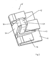
- eine isometrische Darstellung eines Ausschnittes der Montagekonsole;
- Fig. 3
- einen Clip-Stift im eingerasteten Zustand in einem Kanalunterteil;
- Fig. 4
- ein Montagemodell zur Befestigung des Leitungsführungskanals mit Montagefuß.
- In
Fig. 1 ist eine Ausführungsform eines erfindungsgemäßen Leitungsführungskanals gezeigt. Der Kanal selbst besteht aus einem Kanalunterteil 1 mit Boden 3 und zwei U-förmig nach oben ausgeformten Seitenwänden 4, die gegebenenfalls Deckelhalteprofile 6 aufweisen, sowie gegebenenfalls einem Kanaloberteil (nicht dargestellt). Am Boden 3 des Kanalunterteils 1 befinden sich bevorzugt in regelmäßigen Abständen Stiftaufnahmen 2, die vorzugsweise in parallelen Reihen angeordnet sind. Die Stiftaufnahmen 2 und die Clip-Stifte 12 sind in ihrem Profil vorzugsweise so ausgestaltet, dass der Leitungsführungskanal nur in einer bestimmten Orientierung mit der Montagekonsole 14 verrastet werden kann, wodurch eine Fehlmontage vermieden wird. Vorzugsweise ist der Längssteg 21 des Stützkörpers 18, der die Front- und Rückschenkel 19 verbindet, länger als der Quersteg, der die beiden seitlichen Rastschenkel 13 verbindet. - Die Montagekonsole 14 umfasst einen oder mehrere Clip-Stifte 12, die durch die Stiftaufnahme 2 des Kanalunterteils 1 durchgreifen und den Leitungsführungskanal mit dieser verrasten. Vorzugsweise sind die Clip-Stifte 12 entlang der Montagekonsole 14 an einer Schiene beweglich (nicht gezeigt). Dadurch können einzelne Clip-Stifte 12 genau in Position gebracht werden.
- In
Fig. 2 ist der Aufbau der Clip-Stifte 12 genauer gezeigt. Der Clip-Stift 12 ist an einer Basis 11 ausgebildet und besteht aus einem bügelartigen U-förmigen Stützkörper 18, der aus zwei durch einen Längssteg 21 verbundenen Front- und Rückschenkeln 19 gebildet wird. Die Übergangskanten des Längsstegs 21 sind vorzugsweise abgerundet, um das Einführen der Clip-Stifte 12 in die Stiftaufnahmen 2 zu erleichtern. Der Rückschenkel 19 des Clip-Stiftes 12 geht in einen rechtwinkelig zu diesem angeordneten Führungsschenkel über, der in etwa parallel zur Basis 11 verläuft. Seitlich sind an dem Clip-Stift 12 zwei nach unten und etwa im spitzen Winkel geneigte federnde Rastschenkel 13 ausgebildet. - Vorzugsweise sind die beiden Rastschenkel 13 unterschiedlich lang ausgebildet. Für Stahlblechkanäle kann es beispielsweise erforderlich sein, dass der Rastschenkel 13 eine größere Länge aufweist als ein Rastschenkel 13 für andere Brüstungskanäle. Das Montageelement 14 besteht vorzugsweise aus einer Basis 11 und weist links- und rechtsseitig zwei nach innen gebogene federnde Ausgleichsschenkel 16 auf, die quer zu den Rastschenkeln 13 angeordnet sind.
- Durch die unterschiedliche Länge der beiden federnden Rastschenkel 13 und der federnden Ausgleichsschenkel 16 ist es möglich, die Montagekonsole 14 für verschiedene Brüstungskanäle und Stahlblechkanäle mit unterschiedlichen Wandstärken zu verwenden, ohne dass ein Austausch der Montagekonsole 14 erfolgen muss. Wenigstens ein freies Ende eines Rastschenkels 13 stützt sich im verasteten Zustand gegen den Boden 3 des Kanalunterteils 1 ab. Handelt es sich hierbei um den längeren Rastschenkel 13, so hängt der kürzere Rastschenkel 13 in der Luft. Stützt sich der kürzere Rastschenkel 13 ab, so ist der längere Rastschenkel 13 in der Stiftaufnahme 2.
- In
Fig. 3 erkennt man den Clip-Stift 12 im verrasteten Zustand am Kanalunterteil 1. Das freie Ende des Clip-Stiftes 12 ist vollständig durch die Stiftaufnahme 2 des Bodens 3 von dem Kanalunterteil 1 geführt. Zum Aufrasten wird das Kanalunterteil 1 lediglich auf die Montagekonsole 14 gedrückt. Dadurch werden die beiden Rastschenkel 13 leicht nach innen gedrückt und federn zurück, sobald der Clip-Stift 12 vollständig durch die Stiftaufnahme 2 geführt ist. Das freie Schenkelende des Rastschenkels 13 stützt sich gegen den Boden 3 des Kanalunterteils 1 ab und verhindert dadurch das Herausfallen des Kanalunterteils 1. Zum Entfernen des Leitungsführungskanals müssen die beiden Rastschenkel 13 lediglich mit der Hand oder mit Werkzeug nach innen in die Stiftaufnahmen 2 unter gleichzeitigem Herausziehen des Kanalunterteils 1 gedrückt werden. - In
Fig. 4 erkennt man eine Ausführungsform der erfindungsgemäßen Montagevorrichtung als Montageskizze, bestehend aus Montagekonsole 14 mit den darin ausgeformten Clip-Stiften 12 sowie einem mit der Montagekonsole 14 verbundenen Tragarm 22, der über ein Einstellrad 24 in dessen Länge veränderbar ist. Der Tragarm 22 ist mit einem Montagefuß 20 verbunden. Der Montagefuß 20 kann zur wandseitigen oder deckenseitigen Montage mit dem Gebäudeteil verbunden werden.
Claims (7)
- Leitungsführungskanal mit Montagevorrichtung, umfassend:- gegebenenfalls ein Kanaloberteil,- ein Kanalunterteil (1) mit- einem Boden (3)- mit darin eingebrachten Stiftaufnahmen (2)- zwei Seitenwänden (4), gegebenenfalls mit Deckelhalteprofilen (6),- eine Montagekonsole (14) zur Befestigung des Kanalunterteils (1),gekennzeichnet durch die Merkmale:- an der Montagekonsole (14) befinden sich Clip-Stifte (12), die in die Stiftaufnahmen (2) des Kanalunterteils (1) durchgreifen,- die Clip-Stifte (12) werden gebildet durch- einen bügelartigen Stützkörper (18) mit über einen Längssteg (21) verbundenen Front- und Rückschenkeln (19), und- wenigstens zwei seitliche nach unten und im spitzen Winkel nach außen geneigte federnde Rastschenkel (13), wobei zumindest ein freies Schenkelende eines Rastschenkels (13) sich im eingerasteten Zustand gegen das Kanalunterteil (1) abstützt.
- Leitungsführungskanal nach Anspruch 1, dadurch gekennzeichnet, dass die beiden Rastschenkel (13) unterschiedlich lang sind.
- Leitungsführungskanal nach einem der vorhergehenden Ansprüche, dadurch gekennzeichnet, dass die Montagekonsole (14) zwei federnde Ausgleichsschenkel (16) umfasst.
- Leitungsführungskanal nach Anspruch 2, dadurch gekennzeichnet, dass die Ausgleichsschenkel (16) beidseitig des Clip-Stiftes (12) und quer zu den Rastschenkeln (13) angeordnet sind.
- Leitungsführungskanal nach einem der vorhergehenden Ansprüche, dadurch gekennzeichnet, dass der Längssteg (21) des Stützkörpers (18), der die Front- und Rückschenkel (19) verbindet, länger ist als der Quersteg, der die beiden Rastschenkel (13) verbindet.
- Leitungsführungskanal nach einem der vorhergehenden Ansprüche, dadurch gekennzeichnet, dass die Übergangskanten des Längsstegs (21) zu den Front- und Rückschenkel (19) abgerundet sind.
- Leitungsführungskanal nach einem der vorhergehenden Ansprüche, dadurch gekennzeichnet, dass die Montagekonsole (14) mit einem Trägerarm (22) und einem Montagefuß (20) verbunden ist, dessen Länge über ein Einstellrad (24) verstellbar ist.
Applications Claiming Priority (1)
| Application Number | Priority Date | Filing Date | Title |
|---|---|---|---|
| DE200720013520 DE202007013520U1 (de) | 2007-09-27 | 2007-09-27 | Leitungsführungskanal mit Montagevorrichtung |
Publications (3)
| Publication Number | Publication Date |
|---|---|
| EP2043215A2 true EP2043215A2 (de) | 2009-04-01 |
| EP2043215A3 EP2043215A3 (de) | 2010-12-01 |
| EP2043215B1 EP2043215B1 (de) | 2019-01-02 |
Family
ID=40243977
Family Applications (1)
| Application Number | Title | Priority Date | Filing Date |
|---|---|---|---|
| EP08015498.2A Not-in-force EP2043215B1 (de) | 2007-09-27 | 2008-09-03 | Leitungsführungskanal mit Montagevorrichtung |
Country Status (3)
| Country | Link |
|---|---|
| EP (1) | EP2043215B1 (de) |
| DE (1) | DE202007013520U1 (de) |
| DK (1) | DK2043215T3 (de) |
Cited By (1)
| Publication number | Priority date | Publication date | Assignee | Title |
|---|---|---|---|---|
| DE202010013632U1 (de) | 2010-09-25 | 2011-12-28 | Tehalit Gmbh | Kabelkanalsystem mit Wandanschlussblende |
Family Cites Families (3)
| Publication number | Priority date | Publication date | Assignee | Title |
|---|---|---|---|---|
| EP0161226B1 (de) * | 1984-04-05 | 1991-02-27 | Handelsbolaget under Firma Elof Hansson | Installationskanal und Montagekonsole dafür |
| SE462193B (sv) * | 1988-06-06 | 1990-05-14 | Handelsbolag Elof Hansson | Anordning foer loesgoerbar sammankoppling av installationskanal med till en yta faestbar konsol |
| JP4206911B2 (ja) * | 2003-11-18 | 2009-01-14 | 株式会社明電舎 | 配線ダクトの取付構造 |
-
2007
- 2007-09-27 DE DE200720013520 patent/DE202007013520U1/de not_active Expired - Lifetime
-
2008
- 2008-09-03 DK DK08015498.2T patent/DK2043215T3/da active
- 2008-09-03 EP EP08015498.2A patent/EP2043215B1/de not_active Not-in-force
Non-Patent Citations (1)
| Title |
|---|
| None |
Cited By (2)
| Publication number | Priority date | Publication date | Assignee | Title |
|---|---|---|---|---|
| DE202010013632U1 (de) | 2010-09-25 | 2011-12-28 | Tehalit Gmbh | Kabelkanalsystem mit Wandanschlussblende |
| EP2434597A2 (de) | 2010-09-25 | 2012-03-28 | Tehalit GmbH | Kabelkanalsystem mit Wandanschlussblende |
Also Published As
| Publication number | Publication date |
|---|---|
| DE202007013520U1 (de) | 2009-02-19 |
| EP2043215B1 (de) | 2019-01-02 |
| EP2043215A3 (de) | 2010-12-01 |
| DK2043215T3 (da) | 2019-04-15 |
Similar Documents
| Publication | Publication Date | Title |
|---|---|---|
| DE102016124609A1 (de) | Verteilerkasten zum Einbau in eine Wandöffnung | |
| DE102012014979A1 (de) | Montagesystem für die Anordnung von beispielsweise elektrischen Einrichtungen insbesondere in Schaltschränken | |
| EP2043215B1 (de) | Leitungsführungskanal mit Montagevorrichtung | |
| EP1123572A1 (de) | Bausatz für kabelkanäle eines arbeitsplatz-möbels | |
| DE2838371C2 (de) | Mehrfach-Schutzkontaktstromsteckschiene | |
| DE202009015319U1 (de) | Kabelhalter für eine Montageschiene | |
| EP0933853B1 (de) | Träger zur Aufnahme eines Steckdosenblocks auf einem Sockelleistenkanal | |
| DE2646841A1 (de) | Seitenwange an einem arbeitstisch, vorzugsweise buerotisch | |
| EP3419128A1 (de) | Steckdosenleiste für einen verteilerkasten | |
| DE102014107085B3 (de) | Elektroinstallationsvorrichtung für den Betonbau | |
| DE10325938B4 (de) | Kleinverteiler | |
| DE19737893B4 (de) | Installationskanal mit Abdeckung und Potentialausgleichsklammer für den Potentialausgleich zwischen diesen | |
| EP1359650B1 (de) | Anschlussvorrichtung für elektrische Verteiler | |
| DE202015008402U1 (de) | Deckel zur Anordnung an einem Kanalgrundkörper eines Leitungsführungskanals und Leitungsführungskanal mit einem solchen | |
| DE102019119116A1 (de) | Anordnung zur verteilung von gasförmigen und flüssigen medien in einem labor | |
| EP3461963A1 (de) | Trägersystem und system von verbindungselementen zur verbindung von trägern | |
| DE19749335C1 (de) | Frei stehende Halterung für elektrotechnische Modulgeräte | |
| DE102010056066A1 (de) | Verbindungselement zur Erstellung von Medienzellen | |
| EP1376797B1 (de) | Verdrahtungskanal | |
| DE202006015764U1 (de) | Einrichtung zum Anschließen von Arbeitsplätzen an ein Energie-, Daten- und/oder Kommunikationsnetz | |
| DE7037254U (de) | Gestellrahmen | |
| EP2034575B1 (de) | Gerätehalterung zur befestigung von elektroinstallationsgeräten an einem leitungsführungskanal | |
| DE102004050166A1 (de) | Vorrichtung zum Anbringen von Kennzeichnungsschildern in einem Schaltschrank | |
| EP1229623A1 (de) | Kabelkanal | |
| DE2026512C3 (de) | Elektrische Steckdose |
Legal Events
| Date | Code | Title | Description |
|---|---|---|---|
| PUAI | Public reference made under article 153(3) epc to a published international application that has entered the european phase |
Free format text: ORIGINAL CODE: 0009012 |
|
| AK | Designated contracting states |
Kind code of ref document: A2 Designated state(s): AT BE BG CH CY CZ DE DK EE ES FI FR GB GR HR HU IE IS IT LI LT LU LV MC MT NL NO PL PT RO SE SI SK TR |
|
| AX | Request for extension of the european patent |
Extension state: AL BA MK RS |
|
| PUAL | Search report despatched |
Free format text: ORIGINAL CODE: 0009013 |
|
| AK | Designated contracting states |
Kind code of ref document: A3 Designated state(s): AT BE BG CH CY CZ DE DK EE ES FI FR GB GR HR HU IE IS IT LI LT LU LV MC MT NL NO PL PT RO SE SI SK TR |
|
| AX | Request for extension of the european patent |
Extension state: AL BA MK RS |
|
| 17P | Request for examination filed |
Effective date: 20110415 |
|
| AKX | Designation fees paid |
Designated state(s): AT BE BG CH CY CZ DE DK EE ES FI FR GB GR HR HU IE IS IT LI LT LU LV MC MT NL NO PL PT RO SE SI SK TR |
|
| GRAP | Despatch of communication of intention to grant a patent |
Free format text: ORIGINAL CODE: EPIDOSNIGR1 |
|
| STAA | Information on the status of an ep patent application or granted ep patent |
Free format text: STATUS: GRANT OF PATENT IS INTENDED |
|
| INTG | Intention to grant announced |
Effective date: 20180622 |
|
| GRAJ | Information related to disapproval of communication of intention to grant by the applicant or resumption of examination proceedings by the epo deleted |
Free format text: ORIGINAL CODE: EPIDOSDIGR1 |
|
| STAA | Information on the status of an ep patent application or granted ep patent |
Free format text: STATUS: REQUEST FOR EXAMINATION WAS MADE |
|
| GRAS | Grant fee paid |
Free format text: ORIGINAL CODE: EPIDOSNIGR3 |
|
| STAA | Information on the status of an ep patent application or granted ep patent |
Free format text: STATUS: GRANT OF PATENT IS INTENDED |
|
| GRAP | Despatch of communication of intention to grant a patent |
Free format text: ORIGINAL CODE: EPIDOSNIGR1 |
|
| INTC | Intention to grant announced (deleted) | ||
| INTG | Intention to grant announced |
Effective date: 20181015 |
|
| GRAA | (expected) grant |
Free format text: ORIGINAL CODE: 0009210 |
|
| STAA | Information on the status of an ep patent application or granted ep patent |
Free format text: STATUS: THE PATENT HAS BEEN GRANTED |
|
| AK | Designated contracting states |
Kind code of ref document: B1 Designated state(s): AT BE BG CH CY CZ DE DK EE ES FI FR GB GR HR HU IE IS IT LI LT LU LV MC MT NL NO PL PT RO SE SI SK TR |
|
| REG | Reference to a national code |
Ref country code: GB Ref legal event code: FG4D Free format text: NOT ENGLISH |
|
| REG | Reference to a national code |
Ref country code: CH Ref legal event code: EP Ref country code: AT Ref legal event code: REF Ref document number: 1085628 Country of ref document: AT Kind code of ref document: T Effective date: 20190115 |
|
| REG | Reference to a national code |
Ref country code: IE Ref legal event code: FG4D Free format text: LANGUAGE OF EP DOCUMENT: GERMAN |
|
| REG | Reference to a national code |
Ref country code: DE Ref legal event code: R096 Ref document number: 502008016545 Country of ref document: DE |
|
| REG | Reference to a national code |
Ref country code: SE Ref legal event code: TRGR |
|
| REG | Reference to a national code |
Ref country code: DK Ref legal event code: T3 Effective date: 20190408 |
|
| REG | Reference to a national code |
Ref country code: NL Ref legal event code: FP |
|
| REG | Reference to a national code |
Ref country code: LT Ref legal event code: MG4D |
|
| PG25 | Lapsed in a contracting state [announced via postgrant information from national office to epo] |
Ref country code: NO Free format text: LAPSE BECAUSE OF FAILURE TO SUBMIT A TRANSLATION OF THE DESCRIPTION OR TO PAY THE FEE WITHIN THE PRESCRIBED TIME-LIMIT Effective date: 20190402 Ref country code: FI Free format text: LAPSE BECAUSE OF FAILURE TO SUBMIT A TRANSLATION OF THE DESCRIPTION OR TO PAY THE FEE WITHIN THE PRESCRIBED TIME-LIMIT Effective date: 20190102 Ref country code: ES Free format text: LAPSE BECAUSE OF FAILURE TO SUBMIT A TRANSLATION OF THE DESCRIPTION OR TO PAY THE FEE WITHIN THE PRESCRIBED TIME-LIMIT Effective date: 20190102 Ref country code: PT Free format text: LAPSE BECAUSE OF FAILURE TO SUBMIT A TRANSLATION OF THE DESCRIPTION OR TO PAY THE FEE WITHIN THE PRESCRIBED TIME-LIMIT Effective date: 20190502 Ref country code: LT Free format text: LAPSE BECAUSE OF FAILURE TO SUBMIT A TRANSLATION OF THE DESCRIPTION OR TO PAY THE FEE WITHIN THE PRESCRIBED TIME-LIMIT Effective date: 20190102 Ref country code: PL Free format text: LAPSE BECAUSE OF FAILURE TO SUBMIT A TRANSLATION OF THE DESCRIPTION OR TO PAY THE FEE WITHIN THE PRESCRIBED TIME-LIMIT Effective date: 20190102 |
|
| PG25 | Lapsed in a contracting state [announced via postgrant information from national office to epo] |
Ref country code: LV Free format text: LAPSE BECAUSE OF FAILURE TO SUBMIT A TRANSLATION OF THE DESCRIPTION OR TO PAY THE FEE WITHIN THE PRESCRIBED TIME-LIMIT Effective date: 20190102 Ref country code: HR Free format text: LAPSE BECAUSE OF FAILURE TO SUBMIT A TRANSLATION OF THE DESCRIPTION OR TO PAY THE FEE WITHIN THE PRESCRIBED TIME-LIMIT Effective date: 20190102 Ref country code: GR Free format text: LAPSE BECAUSE OF FAILURE TO SUBMIT A TRANSLATION OF THE DESCRIPTION OR TO PAY THE FEE WITHIN THE PRESCRIBED TIME-LIMIT Effective date: 20190403 Ref country code: IS Free format text: LAPSE BECAUSE OF FAILURE TO SUBMIT A TRANSLATION OF THE DESCRIPTION OR TO PAY THE FEE WITHIN THE PRESCRIBED TIME-LIMIT Effective date: 20190502 Ref country code: BG Free format text: LAPSE BECAUSE OF FAILURE TO SUBMIT A TRANSLATION OF THE DESCRIPTION OR TO PAY THE FEE WITHIN THE PRESCRIBED TIME-LIMIT Effective date: 20190402 |
|
| REG | Reference to a national code |
Ref country code: DE Ref legal event code: R097 Ref document number: 502008016545 Country of ref document: DE |
|
| PG25 | Lapsed in a contracting state [announced via postgrant information from national office to epo] |
Ref country code: EE Free format text: LAPSE BECAUSE OF FAILURE TO SUBMIT A TRANSLATION OF THE DESCRIPTION OR TO PAY THE FEE WITHIN THE PRESCRIBED TIME-LIMIT Effective date: 20190102 Ref country code: RO Free format text: LAPSE BECAUSE OF FAILURE TO SUBMIT A TRANSLATION OF THE DESCRIPTION OR TO PAY THE FEE WITHIN THE PRESCRIBED TIME-LIMIT Effective date: 20190102 Ref country code: IT Free format text: LAPSE BECAUSE OF FAILURE TO SUBMIT A TRANSLATION OF THE DESCRIPTION OR TO PAY THE FEE WITHIN THE PRESCRIBED TIME-LIMIT Effective date: 20190102 Ref country code: SK Free format text: LAPSE BECAUSE OF FAILURE TO SUBMIT A TRANSLATION OF THE DESCRIPTION OR TO PAY THE FEE WITHIN THE PRESCRIBED TIME-LIMIT Effective date: 20190102 |
|
| PLBE | No opposition filed within time limit |
Free format text: ORIGINAL CODE: 0009261 |
|
| STAA | Information on the status of an ep patent application or granted ep patent |
Free format text: STATUS: NO OPPOSITION FILED WITHIN TIME LIMIT |
|
| 26N | No opposition filed |
Effective date: 20191003 |
|
| PG25 | Lapsed in a contracting state [announced via postgrant information from national office to epo] |
Ref country code: SI Free format text: LAPSE BECAUSE OF FAILURE TO SUBMIT A TRANSLATION OF THE DESCRIPTION OR TO PAY THE FEE WITHIN THE PRESCRIBED TIME-LIMIT Effective date: 20190102 |
|
| PG25 | Lapsed in a contracting state [announced via postgrant information from national office to epo] |
Ref country code: TR Free format text: LAPSE BECAUSE OF FAILURE TO SUBMIT A TRANSLATION OF THE DESCRIPTION OR TO PAY THE FEE WITHIN THE PRESCRIBED TIME-LIMIT Effective date: 20190102 |
|
| PG25 | Lapsed in a contracting state [announced via postgrant information from national office to epo] |
Ref country code: MC Free format text: LAPSE BECAUSE OF FAILURE TO SUBMIT A TRANSLATION OF THE DESCRIPTION OR TO PAY THE FEE WITHIN THE PRESCRIBED TIME-LIMIT Effective date: 20190102 |
|
| REG | Reference to a national code |
Ref country code: CH Ref legal event code: PL |
|
| PG25 | Lapsed in a contracting state [announced via postgrant information from national office to epo] |
Ref country code: LI Free format text: LAPSE BECAUSE OF NON-PAYMENT OF DUE FEES Effective date: 20190930 Ref country code: LU Free format text: LAPSE BECAUSE OF NON-PAYMENT OF DUE FEES Effective date: 20190903 Ref country code: CH Free format text: LAPSE BECAUSE OF NON-PAYMENT OF DUE FEES Effective date: 20190930 Ref country code: IE Free format text: LAPSE BECAUSE OF NON-PAYMENT OF DUE FEES Effective date: 20190903 |
|
| REG | Reference to a national code |
Ref country code: BE Ref legal event code: MM Effective date: 20190930 |
|
| PG25 | Lapsed in a contracting state [announced via postgrant information from national office to epo] |
Ref country code: BE Free format text: LAPSE BECAUSE OF NON-PAYMENT OF DUE FEES Effective date: 20190930 |
|
| GBPC | Gb: european patent ceased through non-payment of renewal fee |
Effective date: 20190903 |
|
| PG25 | Lapsed in a contracting state [announced via postgrant information from national office to epo] |
Ref country code: GB Free format text: LAPSE BECAUSE OF NON-PAYMENT OF DUE FEES Effective date: 20190903 Ref country code: FR Free format text: LAPSE BECAUSE OF NON-PAYMENT OF DUE FEES Effective date: 20190930 |
|
| REG | Reference to a national code |
Ref country code: AT Ref legal event code: MM01 Ref document number: 1085628 Country of ref document: AT Kind code of ref document: T Effective date: 20190903 |
|
| PG25 | Lapsed in a contracting state [announced via postgrant information from national office to epo] |
Ref country code: AT Free format text: LAPSE BECAUSE OF NON-PAYMENT OF DUE FEES Effective date: 20190903 |
|
| PG25 | Lapsed in a contracting state [announced via postgrant information from national office to epo] |
Ref country code: CY Free format text: LAPSE BECAUSE OF FAILURE TO SUBMIT A TRANSLATION OF THE DESCRIPTION OR TO PAY THE FEE WITHIN THE PRESCRIBED TIME-LIMIT Effective date: 20190102 |
|
| PG25 | Lapsed in a contracting state [announced via postgrant information from national office to epo] |
Ref country code: MT Free format text: LAPSE BECAUSE OF FAILURE TO SUBMIT A TRANSLATION OF THE DESCRIPTION OR TO PAY THE FEE WITHIN THE PRESCRIBED TIME-LIMIT Effective date: 20190102 Ref country code: HU Free format text: LAPSE BECAUSE OF FAILURE TO SUBMIT A TRANSLATION OF THE DESCRIPTION OR TO PAY THE FEE WITHIN THE PRESCRIBED TIME-LIMIT; INVALID AB INITIO Effective date: 20080903 |
|
| PGFP | Annual fee paid to national office [announced via postgrant information from national office to epo] |
Ref country code: SE Payment date: 20220927 Year of fee payment: 15 Ref country code: DK Payment date: 20220928 Year of fee payment: 15 Ref country code: CZ Payment date: 20220819 Year of fee payment: 15 |
|
| P01 | Opt-out of the competence of the unified patent court (upc) registered |
Effective date: 20230606 |
|
| PGFP | Annual fee paid to national office [announced via postgrant information from national office to epo] |
Ref country code: NL Payment date: 20230926 Year of fee payment: 16 |
|
| PGFP | Annual fee paid to national office [announced via postgrant information from national office to epo] |
Ref country code: DE Payment date: 20230927 Year of fee payment: 16 |
|
| REG | Reference to a national code |
Ref country code: DK Ref legal event code: EBP Effective date: 20230930 |
|
| PG25 | Lapsed in a contracting state [announced via postgrant information from national office to epo] |
Ref country code: CZ Free format text: LAPSE BECAUSE OF NON-PAYMENT OF DUE FEES Effective date: 20230903 |
|
| REG | Reference to a national code |
Ref country code: SE Ref legal event code: EUG |
|
| PG25 | Lapsed in a contracting state [announced via postgrant information from national office to epo] |
Ref country code: SE Free format text: LAPSE BECAUSE OF NON-PAYMENT OF DUE FEES Effective date: 20230904 |
|
| PG25 | Lapsed in a contracting state [announced via postgrant information from national office to epo] |
Ref country code: DK Free format text: LAPSE BECAUSE OF NON-PAYMENT OF DUE FEES Effective date: 20230930 |
|
| PG25 | Lapsed in a contracting state [announced via postgrant information from national office to epo] |
Ref country code: DK Free format text: LAPSE BECAUSE OF NON-PAYMENT OF DUE FEES Effective date: 20230930 |
|
| REG | Reference to a national code |
Ref country code: DE Ref legal event code: R119 Ref document number: 502008016545 Country of ref document: DE |
|
| REG | Reference to a national code |
Ref country code: NL Ref legal event code: MM Effective date: 20241001 |
|
| PG25 | Lapsed in a contracting state [announced via postgrant information from national office to epo] |
Ref country code: NL Free format text: LAPSE BECAUSE OF NON-PAYMENT OF DUE FEES Effective date: 20241001 |
|
| PG25 | Lapsed in a contracting state [announced via postgrant information from national office to epo] |
Ref country code: DE Free format text: LAPSE BECAUSE OF NON-PAYMENT OF DUE FEES Effective date: 20250401 |