EP2040118A1 - Lens apparatus and camera - Google Patents
Lens apparatus and camera Download PDFInfo
- Publication number
- EP2040118A1 EP2040118A1 EP08164708A EP08164708A EP2040118A1 EP 2040118 A1 EP2040118 A1 EP 2040118A1 EP 08164708 A EP08164708 A EP 08164708A EP 08164708 A EP08164708 A EP 08164708A EP 2040118 A1 EP2040118 A1 EP 2040118A1
- Authority
- EP
- European Patent Office
- Prior art keywords
- image stabilizing
- unit
- gravitational direction
- stabilizing unit
- lens
- Prior art date
- Legal status (The legal status is an assumption and is not a legal conclusion. Google has not performed a legal analysis and makes no representation as to the accuracy of the status listed.)
- Withdrawn
Links
Images


Classifications
-
- G—PHYSICS
- G03—PHOTOGRAPHY; CINEMATOGRAPHY; ANALOGOUS TECHNIQUES USING WAVES OTHER THAN OPTICAL WAVES; ELECTROGRAPHY; HOLOGRAPHY
- G03B—APPARATUS OR ARRANGEMENTS FOR TAKING PHOTOGRAPHS OR FOR PROJECTING OR VIEWING THEM; APPARATUS OR ARRANGEMENTS EMPLOYING ANALOGOUS TECHNIQUES USING WAVES OTHER THAN OPTICAL WAVES; ACCESSORIES THEREFOR
- G03B5/00—Adjustment of optical system relative to image or object surface other than for focusing
- G03B5/02—Lateral adjustment of lens
-
- G—PHYSICS
- G02—OPTICS
- G02B—OPTICAL ELEMENTS, SYSTEMS OR APPARATUS
- G02B27/00—Optical systems or apparatus not provided for by any of the groups G02B1/00 - G02B26/00, G02B30/00
- G02B27/64—Imaging systems using optical elements for stabilisation of the lateral and angular position of the image
- G02B27/646—Imaging systems using optical elements for stabilisation of the lateral and angular position of the image compensating for small deviations, e.g. due to vibration or shake
-
- G—PHYSICS
- G03—PHOTOGRAPHY; CINEMATOGRAPHY; ANALOGOUS TECHNIQUES USING WAVES OTHER THAN OPTICAL WAVES; ELECTROGRAPHY; HOLOGRAPHY
- G03B—APPARATUS OR ARRANGEMENTS FOR TAKING PHOTOGRAPHS OR FOR PROJECTING OR VIEWING THEM; APPARATUS OR ARRANGEMENTS EMPLOYING ANALOGOUS TECHNIQUES USING WAVES OTHER THAN OPTICAL WAVES; ACCESSORIES THEREFOR
- G03B5/00—Adjustment of optical system relative to image or object surface other than for focusing
- G03B5/04—Vertical adjustment of lens; Rising fronts
-
- H—ELECTRICITY
- H04—ELECTRIC COMMUNICATION TECHNIQUE
- H04N—PICTORIAL COMMUNICATION, e.g. TELEVISION
- H04N23/00—Cameras or camera modules comprising electronic image sensors; Control thereof
- H04N23/60—Control of cameras or camera modules
- H04N23/68—Control of cameras or camera modules for stable pick-up of the scene, e.g. compensating for camera body vibrations
- H04N23/681—Motion detection
- H04N23/6812—Motion detection based on additional sensors, e.g. acceleration sensors
-
- H—ELECTRICITY
- H04—ELECTRIC COMMUNICATION TECHNIQUE
- H04N—PICTORIAL COMMUNICATION, e.g. TELEVISION
- H04N23/00—Cameras or camera modules comprising electronic image sensors; Control thereof
- H04N23/60—Control of cameras or camera modules
- H04N23/68—Control of cameras or camera modules for stable pick-up of the scene, e.g. compensating for camera body vibrations
- H04N23/682—Vibration or motion blur correction
- H04N23/685—Vibration or motion blur correction performed by mechanical compensation
- H04N23/687—Vibration or motion blur correction performed by mechanical compensation by shifting the lens or sensor position
-
- G—PHYSICS
- G03—PHOTOGRAPHY; CINEMATOGRAPHY; ANALOGOUS TECHNIQUES USING WAVES OTHER THAN OPTICAL WAVES; ELECTROGRAPHY; HOLOGRAPHY
- G03B—APPARATUS OR ARRANGEMENTS FOR TAKING PHOTOGRAPHS OR FOR PROJECTING OR VIEWING THEM; APPARATUS OR ARRANGEMENTS EMPLOYING ANALOGOUS TECHNIQUES USING WAVES OTHER THAN OPTICAL WAVES; ACCESSORIES THEREFOR
- G03B2205/00—Adjustment of optical system relative to image or object surface other than for focusing
- G03B2205/0007—Movement of one or more optical elements for control of motion blur
- G03B2205/0015—Movement of one or more optical elements for control of motion blur by displacing one or more optical elements normal to the optical axis
-
- G—PHYSICS
- G03—PHOTOGRAPHY; CINEMATOGRAPHY; ANALOGOUS TECHNIQUES USING WAVES OTHER THAN OPTICAL WAVES; ELECTROGRAPHY; HOLOGRAPHY
- G03B—APPARATUS OR ARRANGEMENTS FOR TAKING PHOTOGRAPHS OR FOR PROJECTING OR VIEWING THEM; APPARATUS OR ARRANGEMENTS EMPLOYING ANALOGOUS TECHNIQUES USING WAVES OTHER THAN OPTICAL WAVES; ACCESSORIES THEREFOR
- G03B2205/00—Adjustment of optical system relative to image or object surface other than for focusing
- G03B2205/0046—Movement of one or more optical elements for zooming
-
- G—PHYSICS
- G03—PHOTOGRAPHY; CINEMATOGRAPHY; ANALOGOUS TECHNIQUES USING WAVES OTHER THAN OPTICAL WAVES; ELECTROGRAPHY; HOLOGRAPHY
- G03B—APPARATUS OR ARRANGEMENTS FOR TAKING PHOTOGRAPHS OR FOR PROJECTING OR VIEWING THEM; APPARATUS OR ARRANGEMENTS EMPLOYING ANALOGOUS TECHNIQUES USING WAVES OTHER THAN OPTICAL WAVES; ACCESSORIES THEREFOR
- G03B2217/00—Details of cameras or camera bodies; Accessories therefor
- G03B2217/005—Blur detection
Definitions
- the present invention relates to a lens apparatus attachable to a camera body, a camera system including the lens apparatus, and a camera having an optical image stabilizing unit for reducing an image shake caused by vibrations, such as a camera shake.
- Japanese Patent Application Laid-Open No. 8-184870 discusses an optical apparatus having an optical image stabilizing unit for reducing image blurring caused by vibrations, such as camera shake.
- the optical apparatus discussed in Japanese Patent Application Laid-Open No. 8-184870 has an image stabilizing unit supported by an elastic member.
- a locking mechanism for fixing the image stabilizing optical unit, when an image stabilization operation is off, is unnecessary.
- the elastic force of the elastic member is set to cancel the self-weight of the image stabilizing unit.
- the image stabilizing unit is set to align with an optical axis when an image stabilization operation is off.
- the optical performance (or lack of optical aberration) of a photographic optical system is basically designed to be best under the condition where the optical axis is not bent. Accordingly, the larger a deviation angle to the optical axis (i.e., an inclined angle of an exit light axis to an incident light axis) becomes, the greater the degradation of an image, such as chromatic aberration or reduction of marginal luminance, increases.
- the image stabilizing optical unit is held as close to the optical axis as possible by increasing the elastic force of the elastic member to decrease an amount of drop of the image stabilizing optical unit due to the self-weight thereof.
- Japanese Patent Application Laid-Open No. 7-199263 discusses a change of the driving range in a direction perpendicular to an optical axis of an image stabilizing optical unit according to a focal length of a photographic optical system.
- the apparatuses respectively discussed in Japanese Patent Application Laid-Open No. 7-199263 and Japanese Patent Application Laid-Open No. 8-184870 do not consider the posture change of a camera (e.g., a posture change between a portrait orientation and a landscape orientation).
- the image stabilizing optical unit may greatly deviate from an optical axis position. Accordingly, there may occur an inappropriate image stabilizing operation.
- the present invention is directed to a lens apparatus and a camera, which can perform a favorable image stabilizing operation within an allowable range of the optical performance (e.g., optical aberration) according to a posture change of an optical apparatus, such as a lens apparatus and a camera, and which can reduce electric power consumption.
- a favorable image stabilizing operation within an allowable range of the optical performance (e.g., optical aberration) according to a posture change of an optical apparatus, such as a lens apparatus and a camera, and which can reduce electric power consumption.
- a lens apparatus as specified in claims 1 to 4.
- a camera as specified in claims 5 to 8.
- Fig. 1 is a cross-sectional view illustrating a lens-interchangeable type single-lens reflex (SLR) digital camera according to an exemplary embodiment of the present invention.
- SLR single-lens reflex
- Fig. 2 is a detailed view illustrating an image stabilizing mechanism according to an exemplary embodiment of the present invention.
- Fig. 3 is a block diagram illustrating a lens-interchangeable type SLR digital camera system according to an exemplary embodiment of the present invention.
- Fig. 4 is a flowchart illustrating operation of the camera system illustrated in Fig. 3 .
- Figs. 5A and 5B are schematic diagrams illustrating how the gravitational direction is determined.
- Fig. 6 is a diagram illustrating a correction range corresponding to each focal length.
- Fig. 7 is a diagram illustrating a driving force needed for image-stabilizing within the correction range corresponding to each focal length.
- Fig. 1 illustrates a lens-interchangeable type SLR digital camera according to an exemplary embodiment of the present invention. As illustrated in Fig. 1 , this SLR camera includes a camera body 1.
- An interchangeable lens 2 is attached to the camera body 1.
- the lens interchangeable type SLR digital camera is an optical apparatus that includes the camera body 1 and the interchangeable lens 2 detachably attached to the camera body 1.
- the camera body 1 has the following components.
- a mirror 3 is located on an optical axis of a light flux passing through the interchangeable lens 2 before photographing is started.
- the mirror 3 reflects a part of the light flux to a finder optical system.
- a part of the light flux is lead to a focus detection unit 5 via a sub-mirror 4.
- the focus detection unit 5 includes a condenser lens which splits an incident light flux into two light fluxes, two separator lenses which re-image the two light fluxes, and a phase difference type automatic focusing (AF) sensor, line sensors such as charge coupled devices (CCDs), which perform photoelectric conversion of the two re-focused object images.
- CMOS complementary metal oxide semiconductor
- CCD charge coupled devices
- the finder optical system includes a pentagonal prism 7 and a finder optical unit 8.
- the photographic optical system constituting the interchangeable lens 2 has the following components, i.e., a first lens unit 11, a second lens unit 12 moveable for focusing, a third lens unit 13 moveable for magnification-varying, and a fourth lens unit 14 (an image stabilizing unit).
- the amount of photographing light flux passing through the first, second, third, and fourth lens units is limited by a diaphragm 15.
- the second lens unit 12 receives a driving force from an AF drive motor 16 and moves along the optical axis to perform focusing.
- the third lens unit 13 is driven in the direction of the optical axis by a transmission mechanism of a zoom ring (not shown).
- the zoom ring can be operated by a photographer, and the transmission mechanism converts the operated force into a driving force acting in the direction of the optical axis to vary magnification.
- the fourth lens unit 14 receives a driving force from an image stabilizing drive actuator 18, which is driven based on a detection output from an angular vibration detection sensor 17 including a gyroscope.
- the fourth lens unit 14 is moved in a direction perpendicular to the optical axis to perform angular vibration correction by bending the optical axis.
- Fig. 2 illustrates the image stabilizing unit 14, which is movable in a direction perpendicular to the optical axis, and the image stabilizing drive actuator 18 illustrated in Fig. 1 in detail.
- a lens 51 which is a component of the image stabilizing unit 14, is held by a lens barrel 52.
- the lens barrel 52 has a pin 52a which engages with a slotted hole 56a formed in a base barrel 56 (to be described below) and supports the lens 51 so that the lens 51 is movable in a direction perpendicular to the optical axis.
- the lens barrel also restrains the lens 51 from tilting with respect to the direction of the optical axis.
- the lens barrel 52 and the base barrel 56 have a plurality of pins 52a and cams 56a, respectively.
- a driving coil 53 is integrally attached to the lens barrel 52 to drive the lens barrel 52 in the vertical direction.
- the driving coil 53 is disposed to face a permanent magnet (not shown) provided on the base barrel 56.
- the driving coil 53 can be energized to generate a driving force in the vertical direction.
- a driving coil 54 is integrally attached to the lens barrel 52 to drive the lens barrel 52 in the horizontal direction.
- the driving coil 54 is disposed to face a permanent magnet (not shown) provided on the base barrel 56.
- the driving coil 54 can be energized to generate a driving force in the horizontal direction.
- Compression springs 55 are elastic members for urging the lens barrel 52 from four directions. Although the present embodiment uses a compression spring as the elastic member, a tension spring can be used, instead of the compression spring. The present embodiment includes a plurality of such elastic members.
- a holding position of the lens barrel 52 is determined by the balance between the elastic force of the compression spring 55 and the self-weight of the image stabilizing optical unit 14, which includes the lens 51 and the lens barrel 52, when the driving coils 53 and 54 are not energized.
- the position of the lens barrel 52 is determined by the balance between the elastic force of the compression spring 55 and the sum of the driving force generated by the driving coils 53 and 54 and the force of the gravity due to the self-weight of the lens barrel 52.
- the base barrel 56 (a stationary member, i.e. one which does not move for image stabilization) supports the entire image stabilizing optical unit 14 via a plurality of compression springs 55.
- Sensor magnets 57a and 57b are integrally fixed to the lens barrel 52.
- the sensor magnets 57a and 57b face Hall elements (not shown) attached to the base barrel 56.
- the sensor magnets 57a and 57b move together with the lens barrel 52.
- the position of the image stabilizing optical unit 14 is detected.
- Fig. 3 is a block diagram illustrating a lens-interchangeable type SLR digital camera system, which includes a camera body 100 and an interchangeable lens 200 corresponding to the camera body 1 and the interchangeable lens 2 illustrated in Fig. 1 .
- a camera central processing unit (CPU) 101 is a microcomputer.
- the camera CPU 101 controls operation of each portion in the camera body 100.
- the camera CPU 101 transmits and receives information to and from a lens CPU 201 via a camera contact 102.
- the information transmitted by the camera CPU 101 to the lens CPU 201 includes focus state detection information.
- the camera contact 102 includes a signal transmission contact for transmitting signals to the interchangeable lens 200, and a power supply contact for supplying electric power to the interchangeable lens 200.
- a power switch 103 can be operated by a user.
- the camera CPU 101 is started by operating the power switch 103. Then, each of the actuator and the sensor in the system can be supplied with electric power and the system can be operated.
- a two-stage stroke type release switch 104 can be operated by a user.
- a signal output from the release switch 104 is input to the camera CPU 101.
- the camera CPU 101 performs the following operation in response to a signal output from the release switch 104.
- the camera CPU 101 When a signal output from the release switch 104 is an ON-signal of the first-stroke switch SW1, the camera CPU 101 causes a photometric circuit 105 to determine an exposure amount.
- the focus state of an object in an AF detection area is detected by a focus state detection circuit 106 including an AF sensor.
- an amount of displacement of the second lens unit 12 is determined by the camera CPU 101. Then, a focusing operation is performed by moving the second lens unit 12 in the interchangeable lens 200. Thus, the system becomes ready for photographing.
- the camera CPU 101 When it is detected that the second stroke switch (SW2) is operated, the camera CPU 101 sends a diaphragm operating instruction to the lens CPU 201 provided in the interchangeable lens 200.
- the camera CPU 101 sends an exposure start instruction to an exposure circuit 107 to perform a mirror-up operation and to release the shutter.
- photoelectric conversion of an object image formed by the photographic optical system is performed in an imaging unit 108.
- the photoelectrically converted signals are further converted into digital data by a signal processing unit 109.
- the digital data is output therefrom as image data.
- the image data is recorded by an image recording unit 110 on a recording medium, such as a semiconductor memory (a flash memory), a magnetic disk, and an optical disk.
- a recording medium such as a semiconductor memory (a flash memory), a magnetic disk, and an optical disk.
- the lens CPU 201 controls operation of each unit in the interchangeable lens 200. Also, the lens CPU 201 communicates with the camera CPU 101 via a lens contact 202 when the interchangeable lens 200 is mounted on the camera body 100.
- the lens contact 202 includes a signal transmission contact to which signals are transmitted from the camera body 100, and a power supply contact to which electric power is supplied from the camera body 100.
- An image stabilization operation switch 203 can be operated by a user to determine whether to perform an image stabilizing operation (image stabilization operation).
- An angular vibration detection unit 204 (a vibration detection unit) includes a detection portion that includes a gyroscope, and a calculation output portion.
- the detection portion detects an angular velocity of a vertical vibration (pitch direction) and that of a horizontal vibration (yaw direction) of a camera according to an instruction sent from the lens CPU 201.
- the calculation output portion performs an electrical integration or a mechanical integration on an output signal of the detection portion to obtain and output a displacement signal to the lens CPU 201.
- the image stabilizing optical mechanism 205 is configured such that the lens barrel 52 that holds the lens 51 is suspended by the compression spring 55 (an elastic member), and that the lens barrel 52 is driven by the driving units in two directions, i.e., the horizontal direction and the vertical direction in a plane perpendicular to the optical axis.
- a position detection unit 206 monitors the position of the image stabilizing optical unit 14 in the plane perpendicular to the optical axis.
- a correction drive control unit 207 controls and drives the image stabilizing unit 14 within a predetermined correction range in a plane perpendicular to the optical axis, based on a correction range and position set by a correction range and position setting unit 209.
- the correction range and position setting unit 209 sets a driving range of the image stabilizing optical unit 14 in a plane perpendicular to the optical axis.
- the correction drive control unit 207 determines a target displacement position (target driving position) of the image stabilizing optical unit 14, which is movable in a direction perpendicular to the optical axis, based on a vibration detection information output from the angular vibration detection unit 204.
- the correction drive control unit 207 drives the image stabilizing unit 14 to the target displacement position by performing feedback control based on the difference between a displacement position detected by the position detection unit 206 and the target displacement position.
- the image stabilizing unit 14 is moved in the plane perpendicular to the optical axis to the position set by the correction range and position setting unit 209. Then, the image stabilizing optical unit 14 is controlled to maintain the position thereof.
- a gravitational direction determination unit 208 determines the gravitational direction.
- the gravitational direction determination unit 208 determines a gravitational direction based on the positional information of the image stabilizing optical unit 14, output from the position detection unit 206, in the plane perpendicular to the optical axis thereof, and on the information of the position of the optical axis center of the photographic optical system.
- the gravitational direction determination unit 208 determines the gravitational direction based on the positional information of the image stabilizing optical unit 14, output from the position detection unit 206, in the plane perpendicular to the optical axis thereof, and on the information of the position of the optical axis center of the photographic optical system, which is obtained by detecting a driving voltage supplied by the correction drive control unit 207 and corresponding to a target driving position.
- the correction range and position setting unit 209 sets a drive range of the image stabilizing optical unit 14 in the plane perpendicular to the optical axis.
- the correction range and position setting unit 209 sets the correction range when the image stabilizer is on, and the position for holding the image stabilizing optical unit 14 when the image stabilizer is off, based on the gravitational direction information from the gravitational direction determination unit 208 and on the focal length information from a focal length detection unit 210.
- the focal length detection unit 210 includes a zoom encoder and detects a zoom position of the photographic optical system.
- the focal length detection unit 210 outputs information concerning the focal length to the lens CPU 201.
- a focus unit 211 includes a focus drive portion (corresponding to the AF drive motor 16 illustrated in Fig. 1 ) controlled by the lens CPU 201 based on information concerning the driving amount of a focus lens unit (corresponding to the second lens unit 12 illustrated in Fig. 1 ) to be in focus, sent from the camera CPU 101, and includes also the focus lens unit (corresponding to the second lens unit 12 in Fig.1 ).
- a diaphragm unit 212 (corresponding to the diaphragm 15 illustrated in Fig. 1 ) includes a diaphragm drive portion controlled by the lens CPU 201 based on a diaphragm operating instruction sent from the camera CPU 101, and diaphragm blades driven by the diaphragm drive portion to define an aperture area.
- Fig. 4 is a flowchart illustrating a main operation of the camera system illustrated in Fig. 3 .
- step 1001 the power switch 103 of the camera body 100 is turned on.
- the camera body 100 and the interchangeable lens 200 start to communicate with each other.
- step 1002 the camera CPU 101 determines whether an SW1 signal is output from the release switch 104.
- step 1003 the lens CPU 201 determines whether the image stabilization operation switch 203 is on (i.e., an image stabilization mode (IS mode) is on).
- step 103 If IS mode is on (YES in step 1003), then the processing proceeds to step 1004. If IS mode is off (NO in step 1003), then the processing proceeds to step 1012.
- step 1004 the lens CPU 201 starts detection of a vibration.
- step 1005 the lens CPU 201 calculates a gravitational direction based on information concerning a drive voltage corresponding to the target driving position, which is applied to the correction drive control unit 207, and on a positional information of the image stabilizing optical unit 14.
- step 1006 the lens CPU 201 calculates an optically allowable amount of displacement from the optical axis based on the focal length information.
- step 1007 the lens CPU 201 determines a correction center position and a correction range of the image stabilizing optical unit 14 based on information concerning the gravitational direction and the allowable amount of displacement.
- steps 1005 through 1007 is executed repeatedly at a predetermined timing to update the correction center and the correction range.
- step 1008 the camera CPU 101 starts photometry (light metering) and AF (ranging), and the lens CPU 201 starts AF control (focusing) and image stabilization.
- the camera CPU 101 and the lens CPU 201 repeat a loop of steps 1002 through 1008 and stand by in step 1009 until the switch SW2 is turned on by performing a full pressing of the release button.
- step 1010 If the switch SW2 is turned on (YES in step 1009), the processing proceeds to step 1010.
- step 1010 the camera CPU 101 starts an exposure operation.
- the lens CPU 201 continues image stabilizing.
- step 1011 the camera CPU 101 stores an exposed image. Then, the processing returns to step 1002.
- step 1012 the lens CPU 201 calculates a gravitational direction based on information concerning the position of the image stabilizing optical unit 14.
- the lens CPU 201 calculates an optically allowable amount of displacement from the optical axis based on the focal length information.
- the lens CPU 201 determines a holding position of the image stabilizing optical unit 14 based on the gravitational direction information and information concerning the optically allowable amount of displacement.
- step 1015 the lens CPU 201 drives the image stabilizing optical unit 14 to the holding position determined in step 1014. Then, the lens CPU 201 electrically holds the image stabilizing optical unit 14 at the determined holding position.
- steps 1012 through 1015 is executed repeatedly at a predetermined timing to update the holding position.
- step 1016 the camera CPU 101 performs AF (ranging operation), and photometry (light metering). Then, the processing proceeds to step 1017.
- step 1017 the camera CPU 101 and the lens CPU 201 repeat a loop of steps 1002 through 1017 and stand by in step 1017 until the switch SW2 is turned on by performing a full pressing of the release button.
- step 1017 If the switch SW2 is turned on (YES in step 1017), the processing proceeds to step 1018, in which the camera CPU 101 performs an exposure operation without performing image stabilizing.
- the lens-interchangeable type SLR digital camera system repeats the above-described sequence of operations until the power switch 103 is turned off. If the power switch 103 is turned off, the communication between the camera CPU 101 and the lens CPU 201 is terminated. In addition, the supply of electric power to the interchangeable lens 200 ceases.
- the image stabilizing optical unit 14 is held by elastic members.
- the driving force from the correction drive control unit 207 is substantially proportional to an amount of displacement from a balanced position of the image stabilizing optical unit 14.
- the acceleration needed for driving affects the driving force. However, it is presumed that an acceleration needed for image-stabilizing is so low as to be negligible.
- each driving unit is composed of a voice coil and a permanent magnet
- an energizing voltage supplied to each driving unit is substantially proportional to the driving force.
- the detected energizing voltage can be converted into an amount of displacement.
- the detection position center of the position detection unit 206 is presumed to be aligned with the optical axis of the image stabilizing unit 14 in a state in which there is no deflection in the elastic members (i.e., in a position in which the image stabilizing unit 14 does not drop due to its weight.
- the difference between the displacement detected by the position detection unit 206 and the displacement amount converted from the driving voltage of the image stabilizing optical unit 14 is equal to a displacement amount due to the self-weight drop of the image stabilizing optical unit 14. Accordingly, the gravitational direction can be calculated.
- Fig. 5A illustrates a case where the camera is held in a horizontal position.
- the position of point A will be determined in two ways such as a the displacement calculated by converting the driving voltage of the image stabilizing optical unit 14 and the displacement detected by the position detection unit 206 as described bellow.
- the displacement (X, Y) calculated by converting the supplied driving voltage: (X, Y) (0.5 mm, 0.2 mm).
- the displacement (X, Y) detected by the position detection unit 206: (X, Y) (0.5 mm, 0 mm).
- the displacement obtained by the calculation shown bellow indicates the balancing point between the self-weight of the image stabilizing optical unit 14 and the elastic force of the elastic member.
- ⁇ (the displacement detected by the position detection unit 206) - (the displacement calculated by converting the supplied driving voltage) ⁇ (-0.2 mm, 0 mm).
- Fig. 5B illustrates a case where the camera is held in a vertical position.
- the position of point B will be obtained in two ways as the displacement calculated by converting the driving voltage of the image stabilizing optical unit 14 and the displacement detected by the position detection unit 206 as described bellow.
- the displacement (X, Y) calculated by converting the supplied driving voltage: (X, Y) (0.7 mm, 0 mm).
- the displacement (X, Y) detected by the position detection unit 206: (X, Y) (0.5 mm, 0 mm).
- the displacement obtained by the calculation bellow indicates the balancing point between the self-weight of the image stabilizing optical unit 14 and the elastic force of the elastic member.
- ⁇ (the displacement detected by the position detection unit 206) - (the displacement calculated by converting the supplied driving voltage) ⁇ (-0.2 mm, 0 mm) Consequently, a gravitational direction can be determined based on the X and Y components (X, Y) of each of the balanced positions.
- correction ranges under the following conditions, based on examples of a shift sensitivity corresponding to each focal length, an optically allowable maximum deviation angle with respect to a main optical axis, and a correction deviation angle during image stabilization, are described.
- the shift sensitivity at the telephoto end is 1 deg/mm (a deviation angle is 1 degree when the image stabilizing optical unit 14 is displaced 1 mm).
- the shift sensitivity at the wide-angle end is 2 deg/mm (a deviation angle is 2 degrees when the image stabilizing optical unit 14 is displaced 1 mm).
- the allowable deviation angle at the telephoto end is 0.5 degrees (a deviation angle and an amount of displacement due to a shift of the optical axis of the image stabilizing optical unit 14 with respect to a main optical axis are 0.5 degrees and 0.5 mm, respectively).
- the allowable deviation angle at the wide-angle end is 0.5 degrees (a deviation angle and an amount of displacement due to a shift of the optical axis of the image stabilizing optical unit 14 with respect to a main optical axis are 0.5 degrees and 0.25 mm, respectively).
- the correction angle at the telephoto end is ⁇ 0.3 degrees (corresponding to a case where the displacement of the image stabilizing optical unit 14 is ⁇ 0.3 mm).
- the correction angle at the wide-angle end is ⁇ 0.3 degrees (corresponding to a case where the displacement of the image stabilizing optical unit 14 is ⁇ 0.15 mm).
- the optical axis of the image stabilizing optical unit 14 is displaced to point P1 from the main optical axis P0 due to the balance between the elastic force of the elastic member and the self-weight of the image stabilizing optical unit 14 before the switch SW1 is turned on.
- the optical axis of the image stabilizing optical unit 14 is presumed to displace 0.2 mm due to the self-weight thereof with respect to the main optical axis P0.
- the deviation angle corresponding to the displacement of the optical axis of the image stabilizing optical unit 14 varies with the focal length of the photographic optical system.
- the deviation angle is 0.2 degrees.
- the deviation angle is 0.4 degrees.
- an optically allowable deviation angle range Rt0 (the maximum deviation angle is 0.5 degrees, and an amount of displacement is 0.5 mm) is determined.
- a correction range center Pt and a correction range Rt dropped in the gravitational direction are determined within the allowable deviation angle range Rt0 based on the gravitational direction information from the gravitational direction determination unit 208.
- the self-weight drop position 0.2 degrees ((the amount of displacement is 0.2 mm) is set to be the correction range center of the image stabilizing unit 14.
- image stabilizing is performed under the condition that the correction deviation angle is ⁇ 0.3 degrees (the amount of displacement thereof is ⁇ 0.3 mm).
- the correction range center Pt is the same as the self-weight drop position P1.
- image stabilizing is performed using this point Pt as a starting point.
- an optically allowable deviation angle range Rw0 (the maximum deviation angle is 0.5 degrees, and an amount of displacement is 0.25 mm) is determined.
- a correction range center Pw and a correction range Rw dropped in the gravitational direction are determined within the allowable deviation angle range Rt0 based on the gravitational direction information output from the gravitational direction determination unit 208.
- a position (the deviation angle is 0.2 degrees, which equals the amount of displacement of 0.1 mm) differing from the self-weight drop position of the image stabilizing unit 14 is set to be the correction range center.
- image stabilizing is performed under the condition that the correction deviation angle is ⁇ 0.3 degrees corresponding to the displacement amount of ⁇ 0.15 mm.
- the correction range center Pw differs from the self-weight drop position P1.
- the optical axis of the image stabilizing unit 14 is moved to point Pw at such a speed that a photographer does not feel uncomfortable when observing an image through a finder. Then, image stabilizing is performed using this point Pt as a starting point.
- the magnitude of the driving thrust force for driving the image stabilizing unit 14 is 0 at the position P1 at which the self-weight of the image stabilizing optical unit 14 balances with the elastic force of the elastic member.
- the spring characteristic of the elastic member for urging the image stabilizing unit 14 is linear, it is necessary that the magnitude of the driving thrust force is proportional to the distance from the self-weight drop position P1.
- the thrust forces needed for driving the image stabilizing unit 14 at the telephoto end and the wide-angle end are compared with each other when correction ranges (the correction ranges Rt and Rw) are set based on the respective focal lengths (the focal length at the telephoto end and the focal length at the wide-angle end).
- the thrust force is represented in terms of the distance from point P1 in Fig. 7 , because the magnitude of the driving thrust force is proportional to the displacement from point P1.
- a driving thrust force Ft is the maximum force in the correction range Rt corresponding to the focal length at the telephoto end.
- a driving thrust force Fw is the maximum force in the correction range Rw corresponding to the focal length at the wide-angle end.
- Fig. 7 illustrates also driving forces Ft' and Fw'.
- the driving thrust force Ft' is the maximum force in the correction range Rt' corresponding to the telephoto end.
- the driving thrust force Fw' is the maximum force in the correction range Rw' corresponding to the wide-angle end.
- the driving voltage needed for driving the image stabilizing unit 14 is proportional to the driving thrust force.
- the image stabilizing unit 14 is driven and held according to the allowable deviation angle determined corresponding to the focal length even when the image stabilization operation mode is off.
- the spring constant of the elastic member is large so that the deviation angle corresponding to the self-weight drop position is sufficiently small in comparison with the allowable deviation angle, it is unnecessary to drive the image stabilizing unit 14.
- the driving range of the image stabilizing unit 14 is determined based on the gravitational information output from the gravitational direction determination unit 208 and the focal length information output from the focal length detection unit 210.
- correction driving is performed around the dropped point caused by the weight of the image stabilizing unit 14 itself within the optically allowable deviation angle determined corresponding to each focal length.
- the voltage supplied to the driving units can be reduced while the optical performance is satisfied.
- the gravitational direction determination unit 208 detects the gravitational direction based on the detected position of the image stabilizing optical unit 14 and on the driving voltage corresponding to the target driving position, which is input to the correction drive control unit 207. Consequently, the correction range can be updated even in the middle of image stabilizing. Accordingly, even when the photographing posture changes during image stabilization, electric power can be saved at all times with keeping the optically allowable range.
- the position of the image stabilizing unit 14 is determined based on the gravitational direction information output from the gravitational direction determination unit 208 and on the focal length information output from the focal length detection unit 210.
- the image stabilizing unit 14 is held at the self-weight drop point in an optically allowable range of the deviation angle corresponding to each focal length, and thus good optical performance and electric power saving can be achieved together.
Abstract
Description
- The present invention relates to a lens apparatus attachable to a camera body, a camera system including the lens apparatus, and a camera having an optical image stabilizing unit for reducing an image shake caused by vibrations, such as a camera shake.
- Japanese Patent Application Laid-Open No.
8-184870 - The optical apparatus discussed in Japanese Patent Application Laid-Open No.
8-184870 - In this optical apparatus, the elastic force of the elastic member is set to cancel the self-weight of the image stabilizing unit. Thus, the image stabilizing unit is set to align with an optical axis when an image stabilization operation is off.
- Generally, the optical performance (or lack of optical aberration) of a photographic optical system is basically designed to be best under the condition where the optical axis is not bent. Accordingly, the larger a deviation angle to the optical axis (i.e., an inclined angle of an exit light axis to an incident light axis) becomes, the greater the degradation of an image, such as chromatic aberration or reduction of marginal luminance, increases.
- Therefore, to obtain the best optical performance, preferably, the image stabilizing optical unit is held as close to the optical axis as possible by increasing the elastic force of the elastic member to decrease an amount of drop of the image stabilizing optical unit due to the self-weight thereof.
- In view of electric power saving, there is a conflicting demand to decrease the elastic force for decreasing the driving force needed to move the image stabilizing optical unit.
- Japanese Patent Application Laid-Open No.
7-199263 U.S. Patent No. 6, 064, 826 ) discusses a change of the driving range in a direction perpendicular to an optical axis of an image stabilizing optical unit according to a focal length of a photographic optical system. - However, the apparatuses respectively discussed in Japanese Patent Application Laid-Open No.
7-199263 8-184870 - The present invention is directed to a lens apparatus and a camera, which can perform a favorable image stabilizing operation within an allowable range of the optical performance (e.g., optical aberration) according to a posture change of an optical apparatus, such as a lens apparatus and a camera, and which can reduce electric power consumption.
- According to a fist aspect of the present invention, there is provided a lens apparatus as specified in claims 1 to 4. According to a second aspect of the present invention, there is provided a camera as specified in claims 5 to 8.
- Further features and aspects of the present invention will become apparent from the following detailed description of exemplary embodiments with reference to the attached drawings.
- The accompanying drawings, which are incorporated in and constitute a part of the specification, illustrate exemplary embodiments, features, and aspects of the invention and, together with the description, serve to explain the principles of the invention.
-
Fig. 1 is a cross-sectional view illustrating a lens-interchangeable type single-lens reflex (SLR) digital camera according to an exemplary embodiment of the present invention. -
Fig. 2 is a detailed view illustrating an image stabilizing mechanism according to an exemplary embodiment of the present invention. -
Fig. 3 is a block diagram illustrating a lens-interchangeable type SLR digital camera system according to an exemplary embodiment of the present invention. -
Fig. 4 is a flowchart illustrating operation of the camera system illustrated inFig. 3 . -
Figs. 5A and 5B are schematic diagrams illustrating how the gravitational direction is determined. -
Fig. 6 is a diagram illustrating a correction range corresponding to each focal length. -
Fig. 7 is a diagram illustrating a driving force needed for image-stabilizing within the correction range corresponding to each focal length. - Various exemplary embodiments, features, and aspects of the invention will now be described in detail with reference to the drawings.
-
Fig. 1 illustrates a lens-interchangeable type SLR digital camera according to an exemplary embodiment of the present invention. As illustrated inFig. 1 , this SLR camera includes a camera body 1. - An
interchangeable lens 2 is attached to the camera body 1. - That is, the lens interchangeable type SLR digital camera according to the exemplary embodiment of the present invention is an optical apparatus that includes the camera body 1 and the
interchangeable lens 2 detachably attached to the camera body 1. - The camera body 1 has the following components.
- A
mirror 3 is located on an optical axis of a light flux passing through theinterchangeable lens 2 before photographing is started. Themirror 3 reflects a part of the light flux to a finder optical system. In addition, through the mirror 3 a part of the light flux is lead to a focus detection unit 5 via a sub-mirror 4. During photographing, themirror 3 is moved away from the optical axis. The focus detection unit 5 includes a condenser lens which splits an incident light flux into two light fluxes, two separator lenses which re-image the two light fluxes, and a phase difference type automatic focusing (AF) sensor, line sensors such as charge coupled devices (CCDs), which perform photoelectric conversion of the two re-focused object images. Animage sensor 6, such as a complementary metal oxide semiconductor (CMOS) sensor or a CCD sensor, on which a light flux passing through theinterchangeable lens 2 forms an image during photographing, performs photoelectric conversion of the focused object image. - The finder optical system includes a
pentagonal prism 7 and a finder optical unit 8. - The photographic optical system constituting the
interchangeable lens 2 has the following components, i.e., afirst lens unit 11, asecond lens unit 12 moveable for focusing, athird lens unit 13 moveable for magnification-varying, and a fourth lens unit 14 (an image stabilizing unit). The amount of photographing light flux passing through the first, second, third, and fourth lens units is limited by adiaphragm 15. - The
second lens unit 12 receives a driving force from anAF drive motor 16 and moves along the optical axis to perform focusing. - The
third lens unit 13 is driven in the direction of the optical axis by a transmission mechanism of a zoom ring (not shown). The zoom ring can be operated by a photographer, and the transmission mechanism converts the operated force into a driving force acting in the direction of the optical axis to vary magnification. - The fourth lens unit 14 (the image stabilizing unit) receives a driving force from an image stabilizing
drive actuator 18, which is driven based on a detection output from an angularvibration detection sensor 17 including a gyroscope. Thus, thefourth lens unit 14 is moved in a direction perpendicular to the optical axis to perform angular vibration correction by bending the optical axis. -
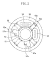
Fig. 2 illustrates theimage stabilizing unit 14, which is movable in a direction perpendicular to the optical axis, and the image stabilizingdrive actuator 18 illustrated inFig. 1 in detail. InFig. 2 , alens 51, which is a component of theimage stabilizing unit 14, is held by alens barrel 52. - The
lens barrel 52 has apin 52a which engages with aslotted hole 56a formed in a base barrel 56 (to be described below) and supports thelens 51 so that thelens 51 is movable in a direction perpendicular to the optical axis. The lens barrel also restrains thelens 51 from tilting with respect to the direction of the optical axis. In addition, thelens barrel 52 and thebase barrel 56 have a plurality ofpins 52a andcams 56a, respectively. - A
driving coil 53 is integrally attached to thelens barrel 52 to drive thelens barrel 52 in the vertical direction. Thedriving coil 53 is disposed to face a permanent magnet (not shown) provided on thebase barrel 56. Thedriving coil 53 can be energized to generate a driving force in the vertical direction. - A
driving coil 54 is integrally attached to thelens barrel 52 to drive thelens barrel 52 in the horizontal direction. Thedriving coil 54 is disposed to face a permanent magnet (not shown) provided on thebase barrel 56. Thedriving coil 54 can be energized to generate a driving force in the horizontal direction. -
Compression springs 55 are elastic members for urging thelens barrel 52 from four directions. Although the present embodiment uses a compression spring as the elastic member, a tension spring can be used, instead of the compression spring. The present embodiment includes a plurality of such elastic members. - A holding position of the
lens barrel 52 is determined by the balance between the elastic force of thecompression spring 55 and the self-weight of the image stabilizingoptical unit 14, which includes thelens 51 and thelens barrel 52, when the driving coils 53 and 54 are not energized. On the other hand, when the driving coils 53 and 54 are energized, the position of thelens barrel 52 is determined by the balance between the elastic force of thecompression spring 55 and the sum of the driving force generated by the driving coils 53 and 54 and the force of the gravity due to the self-weight of thelens barrel 52. - The base barrel 56 (a stationary member, i.e. one which does not move for image stabilization) supports the entire image stabilizing
optical unit 14 via a plurality of compression springs 55.Sensor magnets lens barrel 52. - The
sensor magnets base barrel 56. Thesensor magnets lens barrel 52. Thus, the position of the image stabilizingoptical unit 14 is detected. -
Fig. 3 is a block diagram illustrating a lens-interchangeable type SLR digital camera system, which includes acamera body 100 and aninterchangeable lens 200 corresponding to the camera body 1 and theinterchangeable lens 2 illustrated inFig. 1 . - A camera central processing unit (CPU) 101 is a microcomputer.
- The
camera CPU 101 controls operation of each portion in thecamera body 100. When theinterchangeable lens 200 is attached to thecamera body 100, thecamera CPU 101 transmits and receives information to and from alens CPU 201 via acamera contact 102. - The information transmitted by the
camera CPU 101 to thelens CPU 201 includes focus state detection information. Thecamera contact 102 includes a signal transmission contact for transmitting signals to theinterchangeable lens 200, and a power supply contact for supplying electric power to theinterchangeable lens 200. - A
power switch 103 can be operated by a user. - The
camera CPU 101 is started by operating thepower switch 103. Then, each of the actuator and the sensor in the system can be supplied with electric power and the system can be operated. - A two-stage stroke
type release switch 104 can be operated by a user. - A signal output from the
release switch 104 is input to thecamera CPU 101. Thecamera CPU 101 performs the following operation in response to a signal output from therelease switch 104. - When a signal output from the
release switch 104 is an ON-signal of the first-stroke switch SW1, thecamera CPU 101 causes aphotometric circuit 105 to determine an exposure amount. In addition, the focus state of an object in an AF detection area is detected by a focusstate detection circuit 106 including an AF sensor. - According to a result of detection of the focus state, an amount of displacement of the
second lens unit 12 is determined by thecamera CPU 101. Then, a focusing operation is performed by moving thesecond lens unit 12 in theinterchangeable lens 200. Thus, the system becomes ready for photographing. - When it is detected that the second stroke switch (SW2) is operated, the
camera CPU 101 sends a diaphragm operating instruction to thelens CPU 201 provided in theinterchangeable lens 200. - Then, the
camera CPU 101 sends an exposure start instruction to anexposure circuit 107 to perform a mirror-up operation and to release the shutter. Next, photoelectric conversion of an object image formed by the photographic optical system is performed in animaging unit 108. - The photoelectrically converted signals are further converted into digital data by a
signal processing unit 109. The digital data is output therefrom as image data. - The image data is recorded by an
image recording unit 110 on a recording medium, such as a semiconductor memory (a flash memory), a magnetic disk, and an optical disk. - The
lens CPU 201 controls operation of each unit in theinterchangeable lens 200. Also, thelens CPU 201 communicates with thecamera CPU 101 via alens contact 202 when theinterchangeable lens 200 is mounted on thecamera body 100. - The
lens contact 202 includes a signal transmission contact to which signals are transmitted from thecamera body 100, and a power supply contact to which electric power is supplied from thecamera body 100. - An image
stabilization operation switch 203 can be operated by a user to determine whether to perform an image stabilizing operation (image stabilization operation). - An angular vibration detection unit 204 (a vibration detection unit) includes a detection portion that includes a gyroscope, and a calculation output portion.
- The detection portion detects an angular velocity of a vertical vibration (pitch direction) and that of a horizontal vibration (yaw direction) of a camera according to an instruction sent from the
lens CPU 201. - The calculation output portion performs an electrical integration or a mechanical integration on an output signal of the detection portion to obtain and output a displacement signal to the
lens CPU 201. - As described with reference to
Fig. 2 , the image stabilizingoptical mechanism 205 is configured such that thelens barrel 52 that holds thelens 51 is suspended by the compression spring 55 (an elastic member), and that thelens barrel 52 is driven by the driving units in two directions, i.e., the horizontal direction and the vertical direction in a plane perpendicular to the optical axis. - Because the
lens barrel 52 is suspended by the compression spring (elastic member) 55 as described above, there is no locking unit for latching the image stabilizingoptical unit 14 when the image stabilizer is off. - A
position detection unit 206 monitors the position of the image stabilizingoptical unit 14 in the plane perpendicular to the optical axis. - When the image stabilizer is on, a correction
drive control unit 207 controls and drives theimage stabilizing unit 14 within a predetermined correction range in a plane perpendicular to the optical axis, based on a correction range and position set by a correction range andposition setting unit 209. The correction range andposition setting unit 209 sets a driving range of the image stabilizingoptical unit 14 in a plane perpendicular to the optical axis. - The correction
drive control unit 207 determines a target displacement position (target driving position) of the image stabilizingoptical unit 14, which is movable in a direction perpendicular to the optical axis, based on a vibration detection information output from the angularvibration detection unit 204. - The correction
drive control unit 207 drives theimage stabilizing unit 14 to the target displacement position by performing feedback control based on the difference between a displacement position detected by theposition detection unit 206 and the target displacement position. - Incidentally, when the image stabilizer is off, the
image stabilizing unit 14 is moved in the plane perpendicular to the optical axis to the position set by the correction range andposition setting unit 209. Then, the image stabilizingoptical unit 14 is controlled to maintain the position thereof. - A gravitational
direction determination unit 208 determines the gravitational direction. - When the image stabilizer is off, the gravitational
direction determination unit 208 determines a gravitational direction based on the positional information of the image stabilizingoptical unit 14, output from theposition detection unit 206, in the plane perpendicular to the optical axis thereof, and on the information of the position of the optical axis center of the photographic optical system. - When the image stabilizer is on, the gravitational
direction determination unit 208 determines the gravitational direction based on the positional information of the image stabilizingoptical unit 14, output from theposition detection unit 206, in the plane perpendicular to the optical axis thereof, and on the information of the position of the optical axis center of the photographic optical system, which is obtained by detecting a driving voltage supplied by the correctiondrive control unit 207 and corresponding to a target driving position. - A method for detecting the gravitational direction will be described below in detail with reference to
Figs. 5A and 5B . - The correction range and
position setting unit 209 sets a drive range of the image stabilizingoptical unit 14 in the plane perpendicular to the optical axis. - More particularly, the correction range and
position setting unit 209 sets the correction range when the image stabilizer is on, and the position for holding the image stabilizingoptical unit 14 when the image stabilizer is off, based on the gravitational direction information from the gravitationaldirection determination unit 208 and on the focal length information from a focallength detection unit 210. - The focal
length detection unit 210 includes a zoom encoder and detects a zoom position of the photographic optical system. - The focal
length detection unit 210 outputs information concerning the focal length to thelens CPU 201. - A
focus unit 211 includes a focus drive portion (corresponding to theAF drive motor 16 illustrated inFig. 1 ) controlled by thelens CPU 201 based on information concerning the driving amount of a focus lens unit (corresponding to thesecond lens unit 12 illustrated inFig. 1 ) to be in focus, sent from thecamera CPU 101, and includes also the focus lens unit (corresponding to thesecond lens unit 12 inFig.1 ). - A diaphragm unit 212 (corresponding to the
diaphragm 15 illustrated inFig. 1 ) includes a diaphragm drive portion controlled by thelens CPU 201 based on a diaphragm operating instruction sent from thecamera CPU 101, and diaphragm blades driven by the diaphragm drive portion to define an aperture area. -
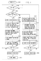
Fig. 4 is a flowchart illustrating a main operation of the camera system illustrated inFig. 3 . - First, in step 1001, the
power switch 103 of thecamera body 100 is turned on. - Consequently, the system starts to supply electric power to the
interchangeable lens 200. - Incidentally, when a new battery is set or when the
interchangeable lens 200 is attached to thecamera body 100, thecamera body 100 and theinterchangeable lens 200 start to communicate with each other. - Next, in step 1002, the
camera CPU 101 determines whether an SW1 signal is output from therelease switch 104. - If the SW1 signal is output (YES in step 1002), then in
step 1003, thelens CPU 201 determines whether the imagestabilization operation switch 203 is on (i.e., an image stabilization mode (IS mode) is on). - If IS mode is on (YES in step 1003), then the processing proceeds to step 1004. If IS mode is off (NO in step 1003), then the processing proceeds to step 1012.
- In
step 1004, thelens CPU 201 starts detection of a vibration. Instep 1005, thelens CPU 201 calculates a gravitational direction based on information concerning a drive voltage corresponding to the target driving position, which is applied to the correctiondrive control unit 207, and on a positional information of the image stabilizingoptical unit 14. - Next, in
step 1006, thelens CPU 201 calculates an optically allowable amount of displacement from the optical axis based on the focal length information. Instep 1007, thelens CPU 201 determines a correction center position and a correction range of the image stabilizingoptical unit 14 based on information concerning the gravitational direction and the allowable amount of displacement. - The process performed in
steps 1005 through 1007 is executed repeatedly at a predetermined timing to update the correction center and the correction range. - Next, in
step 1008, thecamera CPU 101 starts photometry (light metering) and AF (ranging), and thelens CPU 201 starts AF control (focusing) and image stabilization. - The
camera CPU 101 and thelens CPU 201 repeat a loop of steps 1002 through 1008 and stand by instep 1009 until the switch SW2 is turned on by performing a full pressing of the release button. - If the switch SW2 is turned on (YES in step 1009), the processing proceeds to step 1010.
- In
step 1010, thecamera CPU 101 starts an exposure operation. During the exposure operation, thelens CPU 201 continues image stabilizing. - In
step 1011, thecamera CPU 101 stores an exposed image. Then, the processing returns to step 1002. - In
step 1012, thelens CPU 201 calculates a gravitational direction based on information concerning the position of the image stabilizingoptical unit 14. - Next, in
step 1013, thelens CPU 201 calculates an optically allowable amount of displacement from the optical axis based on the focal length information. Instep 1014, thelens CPU 201 determines a holding position of the image stabilizingoptical unit 14 based on the gravitational direction information and information concerning the optically allowable amount of displacement. - Next, in
step 1015, thelens CPU 201 drives the image stabilizingoptical unit 14 to the holding position determined instep 1014. Then, thelens CPU 201 electrically holds the image stabilizingoptical unit 14 at the determined holding position. - The process performed in
steps 1012 through 1015 is executed repeatedly at a predetermined timing to update the holding position. - Next, in
step 1016, thecamera CPU 101 performs AF (ranging operation), and photometry (light metering). Then, the processing proceeds to step 1017. In step 1017, thecamera CPU 101 and thelens CPU 201 repeat a loop of steps 1002 through 1017 and stand by in step 1017 until the switch SW2 is turned on by performing a full pressing of the release button. - If the switch SW2 is turned on (YES in step 1017), the processing proceeds to step 1018, in which the
camera CPU 101 performs an exposure operation without performing image stabilizing. - The lens-interchangeable type SLR digital camera system according to an exemplary embodiment of the present invention repeats the above-described sequence of operations until the
power switch 103 is turned off. If thepower switch 103 is turned off, the communication between thecamera CPU 101 and thelens CPU 201 is terminated. In addition, the supply of electric power to theinterchangeable lens 200 ceases. - Next, a method for calculating the gravitational direction is described with reference to
Figs. 5A and 5B . - The image stabilizing
optical unit 14 is held by elastic members. Thus, if the spring characteristics of the elastic members are linear, the driving force from the correctiondrive control unit 207 is substantially proportional to an amount of displacement from a balanced position of the image stabilizingoptical unit 14. - The acceleration needed for driving affects the driving force. However, it is presumed that an acceleration needed for image-stabilizing is so low as to be negligible.
- If each driving unit is composed of a voice coil and a permanent magnet, an energizing voltage supplied to each driving unit (voice coil in the case of the present embodiment) is substantially proportional to the driving force.
- Accordingly, the detected energizing voltage can be converted into an amount of displacement.
- For example, the detection position center of the
position detection unit 206 is presumed to be aligned with the optical axis of theimage stabilizing unit 14 in a state in which there is no deflection in the elastic members (i.e., in a position in which theimage stabilizing unit 14 does not drop due to its weight. - In this case, the difference between the displacement detected by the
position detection unit 206 and the displacement amount converted from the driving voltage of the image stabilizingoptical unit 14 is equal to a displacement amount due to the self-weight drop of the image stabilizingoptical unit 14. Accordingly, the gravitational direction can be calculated. -
Fig. 5A illustrates a case where the camera is held in a horizontal position. In this state, suppose, if the optical axis of the image stabilizingoptical unit 14 is located at point A, the position of point A will be determined in two ways such as a the displacement calculated by converting the driving voltage of the image stabilizingoptical unit 14 and the displacement detected by theposition detection unit 206 as described bellow.
the displacement (X, Y) calculated by converting the supplied driving voltage: (X, Y) = (0.5 mm, 0.2 mm).
the displacement (X, Y) detected by the position detection unit 206: (X, Y) = (0.5 mm, 0 mm). - The displacement obtained by the calculation shown bellow indicates the balancing point between the self-weight of the image stabilizing
optical unit 14 and the elastic force of the elastic member.
{(the displacement detected by the position detection unit 206) - (the displacement calculated by converting the supplied driving voltage)} = (-0.2 mm, 0 mm). -
Fig. 5B illustrates a case where the camera is held in a vertical position. In this state, if the optical axis of the image stabilizingoptical unit 14 is located at point B, the position of point B will be obtained in two ways as the displacement calculated by converting the driving voltage of the image stabilizingoptical unit 14 and the displacement detected by theposition detection unit 206 as described bellow.
the displacement (X, Y) calculated by converting the supplied driving voltage: (X, Y) = (0.7 mm, 0 mm).
the displacement (X, Y) detected by the position detection unit 206: (X, Y) = (0.5 mm, 0 mm). - The displacement obtained by the calculation bellow indicates the balancing point between the self-weight of the image stabilizing
optical unit 14 and the elastic force of the elastic member.
{(the displacement detected by the position detection unit 206) - (the displacement calculated by converting the supplied driving voltage)} = (-0.2 mm, 0 mm)
Consequently, a gravitational direction can be determined based on the X and Y components (X, Y) of each of the balanced positions. - Next, a change of each of the holding position and the driving range, which correspond to each focal length, is described below with reference to
Fig. 6 . - Hereinafter, correction ranges under the following conditions, based on examples of a shift sensitivity corresponding to each focal length, an optically allowable maximum deviation angle with respect to a main optical axis, and a correction deviation angle during image stabilization, are described.
- The shift sensitivity at the telephoto end is 1 deg/mm (a deviation angle is 1 degree when the image stabilizing
optical unit 14 is displaced 1 mm).
The shift sensitivity at the wide-angle end is 2 deg/mm (a deviation angle is 2 degrees when the image stabilizingoptical unit 14 is displaced 1 mm).
The allowable deviation angle at the telephoto end is 0.5 degrees (a deviation angle and an amount of displacement due to a shift of the optical axis of the image stabilizingoptical unit 14 with respect to a main optical axis are 0.5 degrees and 0.5 mm, respectively).
The allowable deviation angle at the wide-angle end is 0.5 degrees (a deviation angle and an amount of displacement due to a shift of the optical axis of the image stabilizingoptical unit 14 with respect to a main optical axis are 0.5 degrees and 0.25 mm, respectively).
The correction angle at the telephoto end is ± 0.3 degrees (corresponding to a case where the displacement of the image stabilizingoptical unit 14 is ± 0.3 mm).
The correction angle at the wide-angle end is ± 0.3 degrees (corresponding to a case where the displacement of the image stabilizingoptical unit 14 is ± 0.15 mm). - As illustrated in
Fig. 6 , the optical axis of the image stabilizingoptical unit 14 is displaced to point P1 from the main optical axis P0 due to the balance between the elastic force of the elastic member and the self-weight of the image stabilizingoptical unit 14 before the switch SW1 is turned on. According to the present embodiment, the optical axis of the image stabilizingoptical unit 14 is presumed to displace 0.2 mm due to the self-weight thereof with respect to the main optical axis P0. - The deviation angle corresponding to the displacement of the optical axis of the image stabilizing
optical unit 14 varies with the focal length of the photographic optical system. When the focal length of the photographic optical system is a focal length at the telephoto end, the deviation angle is 0.2 degrees. On the other hand, when the focal length of the photographic optical system is a focal length at the wide-angle end, the deviation angle is 0.4 degrees. - Next, a correction range of the image stabilizing
optical unit 14 at the telephoto end when the image stabilization mode is on is described below. - When the focal length is detected to be the telephoto end by the focal
length detection unit 210, an optically allowable deviation angle range Rt0 (the maximum deviation angle is 0.5 degrees, and an amount of displacement is 0.5 mm) is determined. - Then, a correction range center Pt and a correction range Rt dropped in the gravitational direction are determined within the allowable deviation angle range Rt0 based on the gravitational direction information from the gravitational
direction determination unit 208. - In this case, the self-weight drop position 0.2 degrees ((the amount of displacement is 0.2 mm) is set to be the correction range center of the
image stabilizing unit 14. In addition, image stabilizing is performed under the condition that the correction deviation angle is ± 0.3 degrees (the amount of displacement thereof is ± 0.3 mm). - When the focal length of the photographic optical system is a focal length at the telephoto end, the correction range center Pt is the same as the self-weight drop position P1. Thus, after the switch SW1 is turned on, image stabilizing is performed using this point Pt as a starting point.
- Next, a correction range of the image stabilizing
optical unit 14 at the wide-angle end when the image stabilization mode is on is described below. - When the focal length is detected to be the wide-angle end by the focal
length detection unit 210, an optically allowable deviation angle range Rw0 (the maximum deviation angle is 0.5 degrees, and an amount of displacement is 0.25 mm) is determined. - Then, a correction range center Pw and a correction range Rw dropped in the gravitational direction are determined within the allowable deviation angle range Rt0 based on the gravitational direction information output from the gravitational
direction determination unit 208. - In this case, a position (the deviation angle is 0.2 degrees, which equals the amount of displacement of 0.1 mm) differing from the self-weight drop position of the
image stabilizing unit 14 is set to be the correction range center. In addition, image stabilizing is performed under the condition that the correction deviation angle is ± 0.3 degrees corresponding to the displacement amount of ± 0.15 mm. - At the wide-angle end, the correction range center Pw differs from the self-weight drop position P1. Thus, after the switch SW1 is turned on, the optical axis of the
image stabilizing unit 14 is moved to point Pw at such a speed that a photographer does not feel uncomfortable when observing an image through a finder. Then, image stabilizing is performed using this point Pt as a starting point. - Hereinafter, with reference to
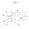
Fig. 7 , a driving thrust force needed for the image-stabilizing driving when the image-stabilizing driving is performed within the determined image stabilizing correction range is described. - The magnitude of the driving thrust force for driving the
image stabilizing unit 14 is 0 at the position P1 at which the self-weight of the image stabilizingoptical unit 14 balances with the elastic force of the elastic member. - If the spring characteristic of the elastic member for urging the
image stabilizing unit 14 is linear, it is necessary that the magnitude of the driving thrust force is proportional to the distance from the self-weight drop position P1. - Referring to
Fig. 7 , the thrust forces needed for driving theimage stabilizing unit 14 at the telephoto end and the wide-angle end are compared with each other when correction ranges (the correction ranges Rt and Rw) are set based on the respective focal lengths (the focal length at the telephoto end and the focal length at the wide-angle end). - The thrust force is represented in terms of the distance from point P1 in
Fig. 7 , because the magnitude of the driving thrust force is proportional to the displacement from point P1. - In
Fig. 7 , a driving thrust force Ft is the maximum force in the correction range Rt corresponding to the focal length at the telephoto end. A driving thrust force Fw is the maximum force in the correction range Rw corresponding to the focal length at the wide-angle end. - In addition, similar correction amounts (at the telephoto end, the correction deviation angle is ± 0.3 degrees corresponding to ± 0.3 mm displacement, and at the wide-angle end, the correction deviation angle is ± 0.3 degrees corresponding to ± 0.15 mm displacement) are determined with the main optical axis P0 as the correction range center. For reference,
Fig. 7 illustrates also driving forces Ft' and Fw'. The driving thrust force Ft' is the maximum force in the correction range Rt' corresponding to the telephoto end. The driving thrust force Fw' is the maximum force in the correction range Rw' corresponding to the wide-angle end. - It is understood according to this comparison that the driving thrust force is reduced compared with a case where image stabilizing is performed around the main optical axis center as the correction range center.
- This is because a thrust force for lifting the self-weight of the
image stabilizing unit 14 is needed in addition to the driving thrust force in order to set the main optical axis as the correction range center. - Additionally, the driving voltage needed for driving the
image stabilizing unit 14 is proportional to the driving thrust force. Thus, as is understood from the above-described result of image stabilizing, electric power can be saved as much as the amount of reduction in the driving thrust force. - In the foregoing description, it has been described that the
image stabilizing unit 14 is driven and held according to the allowable deviation angle determined corresponding to the focal length even when the image stabilization operation mode is off. However, if the spring constant of the elastic member is large so that the deviation angle corresponding to the self-weight drop position is sufficiently small in comparison with the allowable deviation angle, it is unnecessary to drive theimage stabilizing unit 14. - According to the above-described exemplary embodiment, when the image stabilization mode is selected, the driving range of the
image stabilizing unit 14 is determined based on the gravitational information output from the gravitationaldirection determination unit 208 and the focal length information output from the focallength detection unit 210. - Then, correction driving is performed around the dropped point caused by the weight of the
image stabilizing unit 14 itself within the optically allowable deviation angle determined corresponding to each focal length. Thus, the voltage supplied to the driving units can be reduced while the optical performance is satisfied. - In addition, the gravitational
direction determination unit 208 detects the gravitational direction based on the detected position of the image stabilizingoptical unit 14 and on the driving voltage corresponding to the target driving position, which is input to the correctiondrive control unit 207. Consequently, the correction range can be updated even in the middle of image stabilizing. Accordingly, even when the photographing posture changes during image stabilization, electric power can be saved at all times with keeping the optically allowable range. - When an image stabilization mode is not selected, the position of the
image stabilizing unit 14 is determined based on the gravitational direction information output from the gravitationaldirection determination unit 208 and on the focal length information output from the focallength detection unit 210. - Accordingly, the
image stabilizing unit 14 is held at the self-weight drop point in an optically allowable range of the deviation angle corresponding to each focal length, and thus good optical performance and electric power saving can be achieved together. - While the present invention has been described with reference to exemplary embodiments, it is to be understood that the invention is not limited to the disclosed exemplary embodiments. The scope of the following claims is to be accorded the broadest interpretation so as to encompass all modifications, equivalent structures, and functions.
Claims (6)
- A lens apparatus (2, 200) attachable to a camera body (1, 100), the lens apparatus comprising:a photographic optical system (11, 12, 13, 14, 15) including an image stabilizing unit (14) supported by support means (56) via a plurality of elastic members (55);an actuator (53,54) configured to drive the image stabilizing unit (14) in a direction perpendicular to an optical axis thereof;position detection means (206) configured to detect the position of the image stabilizing unit (14) in said direction perpendicular to the optical axis;gravitational direction determination means (208) configured to determine a gravitational direction based on an output from the position detection means(206);setting means (209) configured to set a holding position at which the image stabilizing unit is held based on information concerning the gravitational direction output from the gravitational direction determination means; andcontrol means (207) configured to control the actuator based on information concerning a holding position to move the image stabilizing unit (14) to the holding position.
- A lens apparatus as claimed in claim 1 further comprising vibration detection means (204) configured to detect a vibration of the lens apparatus,
wherein the gravitational direction determination means (208) is configured to determine a gravitational direction based on information concerning a driving target position of the image stabilizing unit determined according to an output from the vibration detection means and based on the output from the position detection means. - A lens apparatus according to claim 1 or claim 2, further comprising focal length detection means (210) configured to detect the focal length of the photographic optical system,
wherein the setting means is operable to set at least one of the holding position at which the image stabilizing unit is held and the driving range in the direction perpendicular to the optical axis of the image stabilizing unit based on the information concerning the gravitational direction output from the gravitational direction determination means and information concerning the focal length output from the focal length detection means. - A camera (1,2,100,200) including:a photographic optical system (11,12,13,14,15) including an image stabilizing unit (14) supported by support means (56) via a plurality of elastic members (55);an actuator (53,54) configured to drive the image stabilizing unit (14) in a direction perpendicular to an optical axis thereof;position detection means (206) configured to detect the position of the image stabilizing optical unit in said direction perpendicular to the optical axis;gravitational direction determination means (208) configured to determine a gravitational direction based on an output from the position detection means (206);setting means (209) configured to set a holding position at which the image stabilizing unit (14) is held based on information concerning the gravitational direction output from the gravitational direction determination means (208); andcontrol means configured to control the actuator (53, 54) based on information concerning a holding position to move the image stabilizing unit to the holding position.
- A camera as claimed in claim 4 further comprising vibration detection means (204) configured to detect a vibration of the camera,
wherein the gravitational direction determination means (208) is configured to determine a gravitational direction based on information concerning a driving target position of the image stabilizing unit determined according to an output from the vibration detection means and based on the output from the position detection means. - The camera according to claim 4 or 5, further comprising focal length detection means (210) configured to detect the focal length of the photographic optical system,
wherein the setting means is operable to set at least one of the holding position at which the image stabilizing unit is held and the driving range in the direction perpendicular to the optical axis of the image stabilizing unit based on the information concerning the gravitational direction output from the gravitational direction determination means and information concerning the focal length output from the focal length detection means.
Applications Claiming Priority (1)
| Application Number | Priority Date | Filing Date | Title |
|---|---|---|---|
| JP2007245543A JP5183135B2 (en) | 2007-09-21 | 2007-09-21 | Interchangeable lenses and optical equipment |
Publications (1)
| Publication Number | Publication Date |
|---|---|
| EP2040118A1 true EP2040118A1 (en) | 2009-03-25 |
Family
ID=40097418
Family Applications (1)
| Application Number | Title | Priority Date | Filing Date |
|---|---|---|---|
| EP08164708A Withdrawn EP2040118A1 (en) | 2007-09-21 | 2008-09-19 | Lens apparatus and camera |
Country Status (5)
| Country | Link |
|---|---|
| US (1) | US7856177B2 (en) |
| EP (1) | EP2040118A1 (en) |
| JP (1) | JP5183135B2 (en) |
| CN (1) | CN101393377B (en) |
| RU (1) | RU2399942C2 (en) |
Cited By (1)
| Publication number | Priority date | Publication date | Assignee | Title |
|---|---|---|---|---|
| EP3343898A1 (en) * | 2016-12-27 | 2018-07-04 | Renesas Electronics Corporation | Camera controller, and a calibration method for a correction lens |
Families Citing this family (14)
| Publication number | Priority date | Publication date | Assignee | Title |
|---|---|---|---|---|
| WO2009093635A1 (en) * | 2008-01-22 | 2009-07-30 | Nikon Corporation | Lens tube, method of adjusting lens tube, method of manufacturing lens tube and imaging device |
| JP5546272B2 (en) * | 2010-02-05 | 2014-07-09 | キヤノン株式会社 | Optical device and control method thereof |
| JP2012033999A (en) * | 2010-07-28 | 2012-02-16 | Sony Corp | Electronic apparatus, connection detection method, and connection detection system |
| US20120057035A1 (en) * | 2010-09-02 | 2012-03-08 | Voss Shane D | Force compensation systems and methods |
| JP5979837B2 (en) * | 2011-09-15 | 2016-08-31 | キヤノン株式会社 | Interchangeable lens and camera system having the same |
| TWI499822B (en) * | 2012-04-25 | 2015-09-11 | Sintai Optical Shenzhen Co Ltd | A lens with dual focus detection points |
| JP5901423B2 (en) * | 2012-05-18 | 2016-04-13 | キヤノン株式会社 | LENS DEVICE, IMAGING SYSTEM, AND LENS DEVICE CONTROL METHOD |
| KR20150097766A (en) | 2012-12-20 | 2015-08-26 | 애플 인크. | Voice coil motor optical image stabilization |
| JP6494202B2 (en) * | 2013-08-07 | 2019-04-03 | キヤノン株式会社 | Image shake correction apparatus, control method thereof, and imaging apparatus |
| USD783077S1 (en) * | 2015-03-16 | 2017-04-04 | Lg Electronics Inc. | Vibration arrestor for compact camera |
| CN205787540U (en) * | 2016-03-09 | 2016-12-07 | 梁建平 | Manual camera lens adapter ring |
| US10473949B2 (en) * | 2017-01-30 | 2019-11-12 | Semiconductor Components Industries, Llc | Systems and methods for an optical image stabilizer system |
| JP7269774B2 (en) * | 2019-03-28 | 2023-05-09 | ニデックインスツルメンツ株式会社 | Optical unit with shake correction function, wiring member, and manufacturing method thereof |
| CN112543321B (en) * | 2019-09-23 | 2022-06-24 | 宁波舜宇光电信息有限公司 | Position compensation detection and correction method, camera module and manufacturing method thereof |
Citations (8)
| Publication number | Priority date | Publication date | Assignee | Title |
|---|---|---|---|---|
| JPH07199263A (en) | 1993-12-30 | 1995-08-04 | Canon Inc | Vibration-proofing controller for camera |
| JPH08184870A (en) | 1994-12-28 | 1996-07-16 | Canon Inc | Oscillation correction device' |
| US6064826A (en) | 1993-12-30 | 2000-05-16 | Canon Kabushiki Kaisha | Device used in image blur prevention apparatus |
| JP2005202358A (en) * | 2003-10-15 | 2005-07-28 | Nikon Corp | Blurring correcting apparatus |
| JP2006220758A (en) * | 2005-02-08 | 2006-08-24 | Canon Inc | Shake correction device, optical equipment, control method for shake correction device |
| JP2007065397A (en) * | 2005-08-31 | 2007-03-15 | Olympus Imaging Corp | Mirror frame, electronic imaging unit and camera |
| JP2007121501A (en) * | 2005-10-26 | 2007-05-17 | Nikon Corp | Camera |
| US20070146883A1 (en) * | 2005-12-09 | 2007-06-28 | Hiroshi Akada | Optical apparatus |
Family Cites Families (4)
| Publication number | Priority date | Publication date | Assignee | Title |
|---|---|---|---|---|
| JP3188733B2 (en) * | 1991-09-06 | 2001-07-16 | キヤノン株式会社 | Image stabilizer |
| JPH0980542A (en) * | 1995-09-12 | 1997-03-28 | Nikon Corp | Image moving device |
| JPH0990456A (en) * | 1995-09-25 | 1997-04-04 | Canon Inc | Optical device and camera |
| JP2003091028A (en) | 2001-09-19 | 2003-03-28 | Canon Inc | Controller for positioning correcting means |
-
2007
- 2007-09-21 JP JP2007245543A patent/JP5183135B2/en not_active Expired - Fee Related
-
2008
- 2008-09-09 US US12/206,953 patent/US7856177B2/en not_active Expired - Fee Related
- 2008-09-19 EP EP08164708A patent/EP2040118A1/en not_active Withdrawn
- 2008-09-19 CN CN2008101497035A patent/CN101393377B/en not_active Expired - Fee Related
- 2008-09-19 RU RU2008137664/28A patent/RU2399942C2/en not_active IP Right Cessation
Patent Citations (8)
| Publication number | Priority date | Publication date | Assignee | Title |
|---|---|---|---|---|
| JPH07199263A (en) | 1993-12-30 | 1995-08-04 | Canon Inc | Vibration-proofing controller for camera |
| US6064826A (en) | 1993-12-30 | 2000-05-16 | Canon Kabushiki Kaisha | Device used in image blur prevention apparatus |
| JPH08184870A (en) | 1994-12-28 | 1996-07-16 | Canon Inc | Oscillation correction device' |
| JP2005202358A (en) * | 2003-10-15 | 2005-07-28 | Nikon Corp | Blurring correcting apparatus |
| JP2006220758A (en) * | 2005-02-08 | 2006-08-24 | Canon Inc | Shake correction device, optical equipment, control method for shake correction device |
| JP2007065397A (en) * | 2005-08-31 | 2007-03-15 | Olympus Imaging Corp | Mirror frame, electronic imaging unit and camera |
| JP2007121501A (en) * | 2005-10-26 | 2007-05-17 | Nikon Corp | Camera |
| US20070146883A1 (en) * | 2005-12-09 | 2007-06-28 | Hiroshi Akada | Optical apparatus |
Cited By (1)
| Publication number | Priority date | Publication date | Assignee | Title |
|---|---|---|---|---|
| EP3343898A1 (en) * | 2016-12-27 | 2018-07-04 | Renesas Electronics Corporation | Camera controller, and a calibration method for a correction lens |
Also Published As
| Publication number | Publication date |
|---|---|
| US20090080875A1 (en) | 2009-03-26 |
| CN101393377A (en) | 2009-03-25 |
| RU2008137664A (en) | 2010-03-27 |
| JP2009075441A (en) | 2009-04-09 |
| US7856177B2 (en) | 2010-12-21 |
| JP5183135B2 (en) | 2013-04-17 |
| CN101393377B (en) | 2012-03-21 |
| RU2399942C2 (en) | 2010-09-20 |
Similar Documents
| Publication | Publication Date | Title |
|---|---|---|
| US7856177B2 (en) | Lens apparatus and camera | |
| US7443422B2 (en) | Blur correction apparatus and camera | |
| EP1607792A2 (en) | Optical apparatus | |
| EP2051127A1 (en) | Optical apparatus including image blur correction device | |
| JP2010091792A (en) | Camera body, lens barrel and camera system | |
| JPH0980533A (en) | Shake correction camera | |
| JP4957479B2 (en) | Camera shake correction control device, camera body including the same, and interchangeable lens | |
| JP2011039436A (en) | Photographing system and lens device | |
| WO2013103137A1 (en) | Blur correction device, lens barrel, and imaging device | |
| JP5293947B2 (en) | Imaging device | |
| JP2006126667A (en) | Camera system, camera, and interchangeable lens | |
| JP2002250952A (en) | Shake correcting device | |
| JP4951803B2 (en) | Camera shake correction control device, camera body including the same, and interchangeable lens | |
| JP2008139640A (en) | Imaging apparatus | |
| JP6187121B2 (en) | Vibration correction device | |
| JPH0980570A (en) | Shake correcting camera | |
| JPH0980559A (en) | Image blurring correcting device | |
| JP2013003325A (en) | Optical device | |
| JP2012042589A (en) | Image shake correction mechanism, lens barrel, and image sensor | |
| JP2007163596A (en) | Optical equipment | |
| JPH0980512A (en) | Image blurring correction device | |
| JP6409922B2 (en) | Vibration correction device | |
| JPH0980510A (en) | Image blurring correction device | |
| JP6743860B2 (en) | Shake correction device | |
| JP2010139734A (en) | Photographing apparatus |
Legal Events
| Date | Code | Title | Description |
|---|---|---|---|
| PUAI | Public reference made under article 153(3) epc to a published international application that has entered the european phase |
Free format text: ORIGINAL CODE: 0009012 |
|
| AK | Designated contracting states |
Kind code of ref document: A1 Designated state(s): AT BE BG CH CY CZ DE DK EE ES FI FR GB GR HR HU IE IS IT LI LT LU LV MC MT NL NO PL PT RO SE SI SK TR |
|
| AX | Request for extension of the european patent |
Extension state: AL BA MK RS |
|
| 17P | Request for examination filed |
Effective date: 20090925 |
|
| AKX | Designation fees paid |
Designated state(s): DE FR GB |
|
| 17Q | First examination report despatched |
Effective date: 20161121 |
|
| GRAP | Despatch of communication of intention to grant a patent |
Free format text: ORIGINAL CODE: EPIDOSNIGR1 |
|
| INTG | Intention to grant announced |
Effective date: 20170620 |
|
| STAA | Information on the status of an ep patent application or granted ep patent |
Free format text: STATUS: THE APPLICATION HAS BEEN WITHDRAWN |
|
| 18W | Application withdrawn |
Effective date: 20171018 |