EP2040079B1 - Markierungsverfahren zur Ausschussmarkierung von Testelementen - Google Patents
Markierungsverfahren zur Ausschussmarkierung von Testelementen Download PDFInfo
- Publication number
- EP2040079B1 EP2040079B1 EP07116749A EP07116749A EP2040079B1 EP 2040079 B1 EP2040079 B1 EP 2040079B1 EP 07116749 A EP07116749 A EP 07116749A EP 07116749 A EP07116749 A EP 07116749A EP 2040079 B1 EP2040079 B1 EP 2040079B1
- Authority
- EP
- European Patent Office
- Prior art keywords
- test
- marking
- test elements
- radiation
- elements
- Prior art date
- Legal status (The legal status is an assumption and is not a legal conclusion. Google has not performed a legal analysis and makes no representation as to the accuracy of the status listed.)
- Active
Links
Images

Classifications
-
- G—PHYSICS
- G01—MEASURING; TESTING
- G01N—INVESTIGATING OR ANALYSING MATERIALS BY DETERMINING THEIR CHEMICAL OR PHYSICAL PROPERTIES
- G01N33/00—Investigating or analysing materials by specific methods not covered by groups G01N1/00 - G01N31/00
- G01N33/48—Biological material, e.g. blood, urine; Haemocytometers
- G01N33/483—Physical analysis of biological material
- G01N33/487—Physical analysis of biological material of liquid biological material
- G01N33/4875—Details of handling test elements, e.g. dispensing or storage, not specific to a particular test method
- G01N33/48764—Test tape taken off a spool
-
- G—PHYSICS
- G21—NUCLEAR PHYSICS; NUCLEAR ENGINEERING
- G21K—TECHNIQUES FOR HANDLING PARTICLES OR IONISING RADIATION NOT OTHERWISE PROVIDED FOR; IRRADIATION DEVICES; GAMMA RAY OR X-RAY MICROSCOPES
- G21K5/00—Irradiation devices
-
- G—PHYSICS
- G01—MEASURING; TESTING
- G01N—INVESTIGATING OR ANALYSING MATERIALS BY DETERMINING THEIR CHEMICAL OR PHYSICAL PROPERTIES
- G01N35/00—Automatic analysis not limited to methods or materials provided for in any single one of groups G01N1/00 - G01N33/00; Handling materials therefor
- G01N35/00029—Automatic analysis not limited to methods or materials provided for in any single one of groups G01N1/00 - G01N33/00; Handling materials therefor provided with flat sample substrates, e.g. slides
-
- G—PHYSICS
- G01—MEASURING; TESTING
- G01N—INVESTIGATING OR ANALYSING MATERIALS BY DETERMINING THEIR CHEMICAL OR PHYSICAL PROPERTIES
- G01N35/00—Automatic analysis not limited to methods or materials provided for in any single one of groups G01N1/00 - G01N33/00; Handling materials therefor
- G01N35/00584—Control arrangements for automatic analysers
- G01N35/00722—Communications; Identification
- G01N35/00732—Identification of carriers, materials or components in automatic analysers
-
- G—PHYSICS
- G01—MEASURING; TESTING
- G01N—INVESTIGATING OR ANALYSING MATERIALS BY DETERMINING THEIR CHEMICAL OR PHYSICAL PROPERTIES
- G01N35/00—Automatic analysis not limited to methods or materials provided for in any single one of groups G01N1/00 - G01N33/00; Handling materials therefor
- G01N35/00029—Automatic analysis not limited to methods or materials provided for in any single one of groups G01N1/00 - G01N33/00; Handling materials therefor provided with flat sample substrates, e.g. slides
- G01N2035/00099—Characterised by type of test elements
- G01N2035/00108—Test strips, e.g. paper
-
- G—PHYSICS
- G01—MEASURING; TESTING
- G01N—INVESTIGATING OR ANALYSING MATERIALS BY DETERMINING THEIR CHEMICAL OR PHYSICAL PROPERTIES
- G01N35/00—Automatic analysis not limited to methods or materials provided for in any single one of groups G01N1/00 - G01N33/00; Handling materials therefor
- G01N35/00029—Automatic analysis not limited to methods or materials provided for in any single one of groups G01N1/00 - G01N33/00; Handling materials therefor provided with flat sample substrates, e.g. slides
- G01N2035/00168—Manufacturing or preparing test elements
-
- Y—GENERAL TAGGING OF NEW TECHNOLOGICAL DEVELOPMENTS; GENERAL TAGGING OF CROSS-SECTIONAL TECHNOLOGIES SPANNING OVER SEVERAL SECTIONS OF THE IPC; TECHNICAL SUBJECTS COVERED BY FORMER USPC CROSS-REFERENCE ART COLLECTIONS [XRACs] AND DIGESTS
- Y10—TECHNICAL SUBJECTS COVERED BY FORMER USPC
- Y10T—TECHNICAL SUBJECTS COVERED BY FORMER US CLASSIFICATION
- Y10T29/00—Metal working
- Y10T29/49—Method of mechanical manufacture
-
- Y—GENERAL TAGGING OF NEW TECHNOLOGICAL DEVELOPMENTS; GENERAL TAGGING OF CROSS-SECTIONAL TECHNOLOGIES SPANNING OVER SEVERAL SECTIONS OF THE IPC; TECHNICAL SUBJECTS COVERED BY FORMER USPC CROSS-REFERENCE ART COLLECTIONS [XRACs] AND DIGESTS
- Y10—TECHNICAL SUBJECTS COVERED BY FORMER USPC
- Y10T—TECHNICAL SUBJECTS COVERED BY FORMER US CLASSIFICATION
- Y10T29/00—Metal working
- Y10T29/53—Means to assemble or disassemble
- Y10T29/53022—Means to assemble or disassemble with means to test work or product
Definitions
- the invention relates to a marking method for marking defective test elements and to a production method for producing test elements, which method comprises a marking method according to the invention. Furthermore, the invention relates to a marking device, in particular for carrying out a marking method according to the invention, and to a production device for producing test elements, which comprises a marking device according to the invention. Furthermore, the invention relates to an analytical test device which uses a test element produced by the production method according to the invention.
- marking and production methods, marking and production devices and analytical test devices are used in particular in chemical analysis and in medical technology.
- analytes such as e.g. Metabolites in samples, especially in liquid samples, e.g. be detected qualitatively and / or quantitatively in blood, urine, interstitial fluid or other body fluids.
- An essential application of the present invention is in the field of blood glucose diagnostics.
- test elements which react sensitively to one or more analytes.
- test elements can be used which comprise at least one test material which changes at least one measurable property in the presence of the analyte in the sample or in contact with the analyte.
- these properties For example, as detailed below, they may be electrical and / or optical properties.
- an essential field of application of the present invention is medical diagnostics.
- monitoring blood glucose levels for diabetics is an essential part of the daily routine.
- the blood glucose concentration must be determined quickly and easily, usually several times a day, in order to be able to take appropriate medical measures if necessary.
- mobile devices In order to limit the daily routine of the diabetic no more than necessary, often corresponding mobile devices are used, which should be easy to transport and handle, so that the measurement of blood glucose concentration, for example, at work or in the spare time and quickly yet easily done can.
- stationary devices can also be used, such as devices that are designed for hospitals, medical practices or care facilities.
- test elements are on the market, some of which work according to different measurement methods.
- Various diagnostic methods are used, for example optical or even electrochemical measuring methods.
- An essential element of these measurement methods are often the already mentioned test elements, which are mostly in the form of test strips.
- these may be electrochemical and / or optical test strips.
- Examples of electrochemical test elements are z.
- Optical test elements are for example in CA 2,050,677 disclosed.
- Other types of test elements, such as implantable test elements (see, eg EP 0 678 308 B1 ) are known and can be used in the context of the present invention.
- test elements are also known which are accommodated in a magazine or in another type of bearing device.
- several test elements can be rigidly connected to one another, for example in the context of a test disk on which several test fields are located.
- Other types of multiple test elements are known for example in the context of tape cassettes, in which a plurality of test elements or test fields are arranged on a common band, so that they can be used, for example, successively.
- Further embodiments of magazines are drum magazines in which a plurality of test elements are accommodated in a magazine drum. Other embodiments are known.
- the reliability of the detection of the analyte plays a crucial role in particular in quantitative detection methods in medical diagnostics.
- a number of other decisions such as deciding on insulin medication or deciding on other medical treatment, usually depend on the outcome of the evidence.
- an efficient quality management is required in the production of the test elements, which reliably prevents incorrect test elements from circulating or, if these have become circulated, being used there.
- This quality management may include a variety of testing methods that may already subject the test elements to certain performance tests during the manufacturing process or after fabrication. For example, tests may be performed which check (e.g., by means of image recognition, electronic measurements, optical measurements, or combinations of measurements) certain functionalities of the test elements and thus, with a certain probability, detect faulty test elements.
- test elements are usually a mass process in which a large number of test elements is produced on a large scale with high throughput. It is therefore generally not possible to identify this test element immediately upon detection of a faulty test element.
- Methods are therefore known from the prior art in which test elements recognized as defective are marked as defective during or after the production process. Examples of such labeling methods are in US 2004/0048359 A1 discloses where defective areas are marked by means of a pen or marker. Another known from the prior art method is in EP 0132790 A2 described.
- a plurality of test elements is produced on a total band, and it is found after finding a fault, a suitable mark in the form of a color dot or a magnetic marker in order then to be able to sort out the faulty test element easily and reliably.
- additional starting materials and auxiliaries are used in the known marking methods, such as, for example, colors for colored dots, lacquers, magnetic materials or similar materials.
- additional excipients and adjuvants may interact with the functionality of the test element and may, for example, affect the functionality of a test material (eg, a test chemistry for the detection of blood glucose or another metabolite). So usually a safety must be for the marking used and auxiliary materials are extensively reviewed and documented, for example, to obtain appropriate regulatory approvals.
- the marking method should enable a simple, fast and reliable marking of faulty test elements, which should manage without a significant increase in production costs.
- a marking method for marking defective test elements a production method including this marking method, a marking device for marking defective test elements, a production device for producing test elements involving a marking device and an analytical test device using test elements produced by the method according to the invention are proposed.
- Advantageous developments of the invention are illustrated in the subclaims. These developments can be realized individually or in combination with each other. The wording of all claims is hereby incorporated by reference.
- test elements are designed to detect at least one analyte in a sample.
- they may be test elements of the types described above known in the art, such as test elements for detecting metabolites in liquid samples, such as, in particular, blood, urine, interstitial adipose tissue or other body fluids.
- test elements can also be used for other types of analytes and samples.
- the test elements may be configured, for example, in strip form, in flake form, in disk form, in the form of strips or in similar configurations, individually or in a plurality of combinations.
- the test elements may be suitable for one or more tests and may in particular comprise one or more test fields to which the sample can be applied or with which the sample can be brought into contact.
- the marking method is designed in such a way that the test elements are at least partially provided with an error mark which contains information about a defectiveness of the test elements. For example, a test element identified as defective may be provided with a corresponding error mark.
- the test elements comprise at least one radiation-sensitive material.
- the test elements are exposed to at least one radiation which is set up and / or selected to effect a marking in the form of at least one optically detectable change in the radiation-sensitive material.
- the marking method according to the invention in addition to the cost of materials for additional markers also accounts for the cost of their procurement, warehousing and release. It also generally does not have to be determined by costly document tests as to whether an interaction of the marking substances with unmarked test elements exists. A strategic dependence on the delivery safety of certain markers is also eliminated.
- test elements contain such test materials, often referred to as "proof chemistry" and which are selected and arranged to alter at least one measurable property in the presence of the at least one analyte in the sample, in particular a measurable electrical and / or optical property.
- proof chemistry often referred to as "proof chemistry”
- detection chemistry used there, which is applied, for example, to test fields of the test elements.
- This detection chemistry or test material generally has radiation-sensitive properties on its own. This is the case in particular when optical test elements are used in which the detection of the at least one analyte takes place, for example, in the form of a color change or a change in fluorescence. With other types of test materials, however, detectable, longer-term changes in the test materials can be brought about by suitable selection of the radiation.
- the detectable changes are such that they are irreversible.
- at least the detectable change should have a stability in the range of a few minutes, preferably a few hours to a few days. If the marking remains on the test elements, for example for later read-out by a suitably equipped analyzer, then even a longer stabilization is required, for example an optically detectable change which is stable over a period of several months to years.
- test material of the test elements itself is used as a radiation-sensitive material and thus for information storage about possible errors, can be completely dispensed with an application of additional substances for marking on the test elements.
- advantages set out above laminate of the requirement of the compatibility test, cost reductions, etc. have a particularly positive effect.
- a mark can be applied to the test elements off the test fields.
- a carrier material for example a carrier tape
- a separate, independent of the test materials or the test chemical marking material having radiation-sensitive properties can be applied to the test elements.
- separate marking fields can be provided, which contain a radiation-sensitive material and which are thus markable.
- a marking on a test field (the test field then having a first radiation-sensitive material) and a marking on a separate marking field (which has a second radiation-sensitive material).
- a test element is also proposed which is suitable for use in such a marking method and which has at least one such marking field separated from the test field (s) with a radiation-sensitive material.
- marking field is meant a functional separation, but not necessarily a strict spatial separation.
- marker fields can adjoin test fields, partially overlap with them, or even be stacked in a layer structure (for example, under the test fields), so that overall the functionality of the test fields is not influenced by the marker fields.
- the at least one optically detectable change in the radiation-sensitive material can then be detected by a suitable sensor and interpreted as a reject mark. Possible embodiments of this detection will be discussed in more detail below.
- each test element which is recognized as free from error, are marked by means of the radiation, whereas each test element recognized as defective remains unmarked.
- Intermediate stages or other types of error marking are also possible, for example in that information about a degree of quality of the test element is "written" into the radiation-sensitive material by the at least one radiation, for example in the form of a bit value.
- the information content of the error mark can therefore be configured differently and can contain information about a defectiveness (which can also include freedom from errors) of the respective marked test element (and / or even other test elements, ie, for example, other test elements from a batch) in various ways. As described above, this may be, for example, the information "faulty", "not faulty", a quality level or similar information.
- This information about the defectiveness of the respective marked test element is introduced into the radiation-sensitive material by means of the at least one radiation.
- the radiation used which in principle could also be a particle radiation, such as a neutron radiation, comprises electromagnetic radiation.
- the use of ultraviolet radiation, ie radiation in the wavelength range between 1 nm and 400 nm has proven to be expedient.
- the wavelength range of 250 nm to 400 nm is particularly preferred.
- the wavelength range between 350 nm and 380 nm is particularly preferred.
- the preferred use of UV light, particularly in said preferred wavelength range, particularly in conjunction with the use of the detection chemistry as an information carrier for the error information is advantageous since many of these test materials or detection chemicals, in particular for optical analyte detection, sensitive react to UV radiation.
- long-term multiple bonds in organic constituents of the test materials can be destroyed by UV irradiation, which in turn can be recognized, for example, by a color change or another optically detectable change.
- incandescent lamps gas discharge lamps, lasers, light-emitting diodes, flash lamps or a combination of such light sources, which preferably in turn emit at least partially in the ultraviolet spectral range.
- the optically detectable change may include, for example, a color change, a change in luminescence (e.g., fluorescence and / or phosphorescence), a change in reflectivity, or a combination of these changes and / or other changes.
- the proposed marking method can be used for example as a "stand alone" method to mark already finished test elements. However, it is particularly preferred to integrate the proposed marking method in one of the proposed embodiments as part of a manufacturing method for producing test elements of the type described. In this manufacturing method, a plurality of the test elements are produced and at least one of the test elements (preferably all test elements and / or samples of the produced test elements) are subjected to an error check.
- this error check can be an optical test (eg a color and / or fluorescence measurement), a visual inspection (eg as part of a pattern recognition, in particular by means of a digital image processing program), a fluorescence test or similar types of error checks or combinations of error checks include.
- an optical test eg a color and / or fluorescence measurement
- a visual inspection eg as part of a pattern recognition, in particular by means of a digital image processing program
- a fluorescence test or similar types of error checks or combinations of error checks include.
- the test elements themselves eg a carrier tape of the test elements
- a detection chemistry eg whether a test field has been applied and / or if this test field has been deformed during application
- Another example of a test criterion of the error test is the homogeneity of the test fields.
- a test chemical is contained homogeneously and / or with a constant layer thickness on a test field.
- This homogeneity can be checked for example by means of an optical control in the visible, infrared or ultraviolet spectral range.
- it is also possible to carry out a layer thickness and / or homogeneity check for example by means of ellipsometric methods, transmission methods, mechanical scanning methods or other conventional layer thickness measuring methods, which can preferably scan a surface or detect it simultaneously.
- errors in the production of the test fields for example, errors in a printing process
- tolerance thresholds for the homogeneity can be specified in order to qualify the test fields or test elements as faultless or faulty.
- a test criterion of error control is a distance control, in which (for example by optical means, for example by means of a pattern recognition) distances of certain elements and / or compared in the test elements with setpoints.
- distance control in which (for example by optical means, for example by means of a pattern recognition) distances of certain elements and / or compared in the test elements with setpoints.
- it can be checked whether test fields have a predefined propriety with one another and / or a predetermined distance from certain markings. Two- or three-dimensional distance monitoring is also possible.
- tolerance ranges can also be specified, within which the measured distances are still tolerable and outside of which the test elements are recognized as defective.
- electrical or electrochemical measuring methods can be used, such as resistance measurements, impedance measurements or similar types of measurements.
- a combination of the mentioned types of error checking and / or other types of error checking can also be used and are known to the person skilled in the art.
- the error check can already take place during the production of the test elements and can thus be integrated, for example, in a production line. Alternatively or additionally, the error check may also be subordinate to the time of manufacture.
- test elements for example thick-film methods, semiconductor-based methods, printing methods or a combination of these and / or further conventional method steps.
- the preparation of the test elements is known to the person skilled in the art.
- a belt method may be used as detailed below.
- the test material can preferably be produced separately and then applied (for example in a lamination process) to the band or another type of carrier.
- the term "defective” is to be interpreted broadly. For example, this may be a "digital" defectiveness, for example in the form of a defect or freedom from errors (tolerance thresholds may also be predetermined in each case, for example thresholds for tolerable errors), or a number of intermediate information may also be included. This intermediate information may, for example, in turn comprise quality levels of the test element tested in each case, which may be e.g. can again be expressed in a bit value.
- the test element can be provided with an error mark, which provides information about includes a defectiveness of the respective test element.
- an error mark which provides information about includes a defectiveness of the respective test element.
- a marking method as described above is used in one of the illustrated embodiments.
- test material for example, at least one test material (test chemistry) of the test element can serve as the information carrier for the marking.
- the labeling method may be designed such that this detection chemistry or test chemistry is correspondingly discolored. In this way, in particular, a test element or a part of the test element (for example a specific test field) can be rendered unusable, so that a false measured value can be excluded in the analyte detection.
- test elements can be sorted out.
- marked test elements can be produced as a band product on a common carrier tape, wherein the band product can then be received, for example, in a tape cassette.
- test elements identified as defective can be cut out before being recorded in the tape cassette, and the remaining, error-free tape can then be reassembled in a splicing step. Sol can be avoided even with bandware faulty test elements. Alternatively or additionally, the tape product can subsequently also be separated, whereby faulty test elements can be sorted out. In this way, it can be essentially ensured in each case that all commercially available test elements are error-free.
- the tape product may also be configured to be received in a tape cassette (as set forth initially in the description of the prior art).
- a test tape may include a plurality of test elements, which may be used sequentially, for example.
- faulty test elements can be specially marked so that they can either not be used, be recognized as faulty by an analyzer, or otherwise incorporated in their use are restricted.
- the production method can furthermore preferably be configured in such a way that it optionally comprises a control step after the at least one method step in which the at least one defect marking is applied.
- This check step can be used to verify that the bad mark has been applied correctly. For example, this can be done by monitoring the at least one optically detectable change in the radiation-sensitive material and comparing it with a desired value.
- this setpoint may be stored in a data memory, such as a data memory (e.g., a shift register), which is also used for the bad mark itself. In this way, it can be checked immediately whether the error mark has been carried out correctly. If it is detected that this is not the case, for example, a warning can be issued to an operator and / or the faulty marked test element can be re-marked and / or rejected.
- a warning can be issued to an operator and / or the faulty marked test element can be re-marked and / or rejected.
- Various other possibilities are conceivable.
- a marking device for marking faulty test elements is further proposed according to the invention.
- the marking device can be set up to carry out a marking method of the type described in one of the variant embodiments.
- the marking device has at least one radiation source in order to apply at least one radiation to the test elements. For the effect of this radiation as well as the possible types of marking in the marking device can be made to the above description.
- the marking device may comprise at least one test device, which is set up to subject at least one of the test elements to an error check. Preferably all test elements or samples of the test elements are subjected to this error check. Regarding the possible embodiment of the error check can also be made to the above description.
- the marking device is arranged to recognize and / or decide whether the test element is faulty. With regard to the term "defective" and its possible meanings, reference may also be made to the above definition.
- the radiation source may, for example, again comprise incandescent lamps, gas discharge lamps, lasers, light-emitting diodes, flash lamps or combinations of these and / or other radiation sources, in particular for generating ultraviolet radiation as defined above and in the preferred wavelength range described above. It is particularly preferred in this case to bring about a high degree of parallelism and thus a high throughput of the marking method when the marking device has a plurality of modularly constructed individual light sources.
- these may be a variety of modular light generator units for generating ultraviolet light.
- These modular light generator units may for example comprise a plurality of identical light generator units, which may be arranged for example in a control cabinet of the marking device. For example, these light generator units can be accommodated in the control cabinet in the form of identical inserts.
- the marking device may comprise at least one application position in which the test elements are wholly or partially provided with the error mark.
- at least one application position in which the test elements are wholly or partially provided with the error mark.
- a plurality of application positions it is also possible to provide a plurality of application positions.
- a test material test chemistry, detection chemistry
- a separate application position can be provided for each test field.
- the marking device further comprises at least one waveguide, which is arranged to direct the radiation from the at least one radiation source to the application position.
- this at least one waveguide may in particular be an optical waveguide. If, as is particularly preferred, ultraviolet light is used as radiation, then this optical waveguide should be adapted to the particular wavelength used.
- rigid or flexible waveguides can be used, for example waveguides with a plastic and / or glass material. Such waveguides can be realized for example as a rigid plastic waveguide.
- the waveguide comprises at least one fiber light guide, that is, a flexible light guide.
- glass fibers and / or, which is particularly preferred, plastic fiber light guides can be used. In each case, depending on the desired properties of the radiation, multimode or single-mode fibers can be used.
- a plurality of fiber optic conductors for example plastic fiber optic cables, can be combined to form fiber bundles.
- the preferred UV light generator units described above which are preferably located in a control cabinet of the marking device, can be connected to the at least one application position via one or more fiber bundles.
- the marking device has at least one cross-sectional transducer.
- This cross-sectional transducer is arranged to hold a plurality of fiber light guides of at least one of the fiber bundles such that the fiber ends of the fiber light guides are arranged in the application position in a predetermined pattern.
- the throughput of the test elements can be increased, since several test elements can be applied in parallel, intensities and radiation doses (by simultaneous application of several fibers and / or by application of several fibers in succession) can be increased, and it could also be written on a single test element multiple error marks simultaneously.
- the test elements are produced in a continuous process.
- the test elements can be produced in the form of a continuous test element tape, which is subsequently singulated as described above or which can be accommodated as a whole or in sections in a tape cassette.
- the pattern of the fiber ends which is generated by the cross-sectional transducer, a simultaneous irradiation in the application position both parallel to a running direction of the tape and, alternatively or additionally, make it possible perpendicular to the direction of the tape.
- It is also possible to process several bands at the same time for example, in which several bands with test elements are generated in parallel. For example, in the production of band goods, first a wide band can be produced with a plurality of respectively parallel test elements, which are then cut into several subbands (for example in a cutting process).
- the marking device can have a guide table in the application position, in which two, preferably at least five, test elements can be acted on simultaneously by the radiation, ie can be marked. For example, five bands or sub-bands with test elements are simultaneously driven through the guide table.
- a line pattern e.g., with a line parallel and / or perpendicular to the moving direction of the tape
- a matrix pattern e.g., with a line parallel and / or perpendicular to the moving direction of the tape
- a matrix pattern e.g., with a matrix pattern, or a rectangular pattern
- Other patterns are of course possible.
- a plurality of cross-sectional transducers parallel to one another for example a plurality of cross-sectional transducers, each with fiber ends arranged in a line. This is particularly advantageous in the embodiment variant described above, in which a plurality of test bands are generated in parallel with test elements, since in this way, for example, each band or subband can be assigned a cross-sectional transducer with a fiber end pattern.
- the marking device may further comprise at least one beam-shaping optical system for beam shaping of the radiation.
- lens systems can be provided in order to bring the markings or the shape of the markings on the test elements into a desired shape, for example a line or rectangular shape.
- a production device for the production of test elements is furthermore proposed which can be set up in particular to produce test elements according to the above-described production method in one of the described variants of the method.
- the manufacturing device has a production device for producing a plurality of test elements.
- production devices known from the prior art can be used for this production device as described above, for example production devices which work with semiconductor and / or thick-film processes and / or printing methods and / or bonding methods.
- the production apparatus can be set up to continuously produce a multiplicity of test elements, for example again in the form of a band process, wherein a multiplicity of test elements are accommodated on a common band. These test elements can then be singulated or the tape can be used as such, for example in a tape cassette.
- the production device has at least one marking device according to one of the embodiments described above.
- the manufacturing device furthermore have at least one sorting device for sorting out test elements marked as defective. If a tape product is produced, for example for a tape cassette with test elements, then it is preferred if the production device further comprises a cutting and splicing device, ie a device which can cut out defective test elements from a tape to subsequently glue this tape together or to others Assemble way, for example by lamination. In this way, a gap-free tape can be produced with defect-free test elements.
- the terms "faulty" and "error free” are to be understood broadly, with reference being made to the above description. For example, again tolerance thresholds can be specified.
- erroneous test elements can also, instead of being sorted out, for example remain on a belt and remain unused later, for example by reading the marking (see also below).
- the manufacturing device may in particular further comprise at least one test device.
- This test device is set up to subject the test elements to an error check.
- the error checking methods already described above can be used, that is, for example, electrical, electrochemical or optical measuring methods or a combination of these error checking methods.
- the test device may comprise a camera by means of which the test elements are recorded.
- an image recognition system may also be provided, which is set up, for example, to detect deviations of a test field and / or a form of the test elements from a predetermined standard (eg by more than a predefined tolerance threshold).
- test light sources for example to check fluorescence properties and / or color properties and / or reflection properties of the test element, for example properties of a test chemistry and / or one or more test fields.
- one or more resistance measuring devices may be provided and / or one or more impedance measuring devices and / or similar devices for electrical or electrochemical fault checking.
- the manufacturing device in particular the test device, alternatively or additionally comprise one or more data memories, which may be volatile and / or non-volatile data storage. In the context of mass production, it is particularly preferred if this at least one data memory comprises at least one shift register.
- a continuous or gradual Manufacturing process can be used in which takes place at one point by means of the error-checking device, the error checking, the results of this error checking in the data memory, in particular the shift register, can be registered.
- a plurality of test elements can be successively tested so that subsequently, by appropriately reading out the shift register, for example from the marking device, a test element currently in the marking device (eg one or more test elements in an application position) respectively of the information or the Information in the shift register can be assigned.
- a marking of the test elements can then take place by means of the marking device.
- the information can later also be used for sorting out the test elements.
- the manufacturing apparatus may comprise at least one control device which is arranged to check whether the marking device has been correctly marked.
- the control device can in turn be loaded with data from a data memory, for example a shift register, wherein preferably the same data is used, to which the marking device can also access and on the basis of which the error marks of the test elements are applied.
- a data memory for example a shift register
- the marking device can also access and on the basis of which the error marks of the test elements are applied.
- the manufacturing device can be configured such that it rejects the incorrectly marked test elements and / or issues a warning to operating personnel or performs similar actions.
- the controller may include one or more photodiodes and / or other types of photodetectors to monitor the at least one optically detectable change in the radiation-sensitive material.
- one or more light sources may be provided, for example, to assist a function of the photodetectors by appropriate action on the radiation-sensitive material.
- an analytical test device for detecting at least one analyte in a sample which comprises at least one test element that is manufactured according to the above-described production method in one of the illustrated variants of the method.
- the analytical test device has an interrogation device which is designed to detect if the test element is marked.
- the interrogator is arranged to detect the at least one optically detectable change in the radiation-sensitive material of the test element.
- this analytical test device may further comprise a control and evaluation device in order to carry out a quantitative and / or qualitative detection of the at least one analyte in the sample by means of the at least one test element. It is particularly preferred if the analytical test apparatus is set up to determine a blood sugar concentration.
- individual test elements can be used, a plurality of test elements which are accommodated in a magazine (wherein, for example, one test element is removed from the magazine each time) or test elements which are accommodated in a tape cassette.
- Other types of test elements are also possible, for example implantable test elements.
- the interrogator is thus configured to interrogate the bad mark of the at least one test element, preferably of the at least one test element being used or to be used. If, in this case, according to the information contained in the error marking, it is recognized that the test element is defective, various actions can be carried out. Among other things, a warning may be issued to a user of the analytical test device, such as via a display, optical display elements (e.g., warning lights), audible signals, or a combination of these capabilities. Alternatively or additionally, a test with the marked test element can be prevented. Again alternatively or additionally, it can be caused that a new test element is requested from a plurality of test elements received in a magazine.
- a warning may be issued to a user of the analytical test device, such as via a display, optical display elements (e.g., warning lights), audible signals, or a combination of these capabilities.
- a test with the marked test element can be prevented. Again alternatively or additionally, it can be caused that a new test element is
- test elements in this magazine may be individual test elements or flexible or rigidly connected test elements.
- test elements in this magazine may be individual test elements or flexible or rigidly connected test elements.
- tape cassette so that, for example, in the case of error detection, it is possible to continue to wind from one test field to a next test field.
- FIG. 1 An exemplary embodiment of a production device 110 according to the invention for producing test elements for detecting at least one analyte in a sample is shown.
- the test elements are in FIG. 1 with the reference numerals 112, 114 and 116, depending on the state of production or stage in which these test elements are located within the manufacturing device 110 or depending on the design of these test elements.
- FIG. 1 The individual elements of the manufacturing device 110 are shown in FIG. 1 arranged only symbolically.
- a continuous production process is shown, in which the test elements are first produced as a tape product 116 on an endless belt 118.
- this endless belt 118 can be a paper belt, in particular a multilayer, coated paper belt.
- other support materials can also be used, for example plastic tapes, ceramic tapes, composite materials and similar support materials.
- the production direction from the starting material to the finished test elements 112,114 takes place in FIG. 1 from left to right, what in FIG. 1 symbolically indicated by the arrow 120.
- discontinuous processes are also possible, for example batch processes in which test elements are produced individually or in batches. This can also be done with band-shaped goods, for example by tape goods is wound in sections on carrier rolls in order to be stored and / or to be passed to other sections of the process.
- the manufacturing process may be interrupted, so that, for example, the test elements are manufactured in different stages of production at different locations (for example, at different locations).
- the illustrated sequence of the individual process steps of the manufacturing process of the manufacturing device 110 is not absolutely necessary, so that, for example, testing and marking of semi-finished test elements can be done, so that, for example, testing and marking can be followed by further production steps.
- the manufacturing device 110 has a production device 122, which in FIG. 1 only symbolically indicated.
- the endless belt 118 8 can be provided with test fields, in each of which a test material (also referred to below as test chemistry or detection chemistry) can be applied to the endless belt 118.
- a test material also referred to below as test chemistry or detection chemistry
- This application can be done for example by sticking, which in FIG. 1 symbolically indicated by an adhesive station 123.
- each test fields with the test material (test chemistry, detection chemistry) are glued to the substrate.
- markings can also be applied, for example printed, onto the carrier tape 118, for example markings which serve for later positioning of the test elements 116 in an analytical test device.
- the production device 122 may comprise various individual devices for producing the test elements 116, for example coating nozzles, printing devices (eg screen, stencil, tampon, inkjet or flexographic printing devices) or other types of production devices or combinations of production devices. Also, for example, several bands can be merged as support materials. It is also possible to subdivide the production partially into separate methods, so that, for example, semi-finished products, such as a printed carrier tape, are fed to the production apparatus 122. On the facilities of the production device 122, which are known to those skilled in the production of test elements, will not be discussed here.
- the production device 122 is set up in such a way that it produces a broad carrier strip 118 on which a plurality of test elements 116 are arranged parallel to one another.
- the band 118 may initially be designed so that five such test element tracks are arranged next to one another. These can then, for example, by longitudinal cuts in a cutting device (in FIG. 1 symbolically labeled 125) into individual test element bands. This cutting can be done in different stages of the FIG. 1 done manufacturing process shown.
- a cutting device in FIG. 1 symbolically labeled 125
- Another embodiment is possible, so for example, a configuration with only a carrier tape 118th
- the manufacturing device 110 further has a central control unit 124 in this exemplary embodiment.
- this control unit 124 may alternatively also be of a decentralized design, so that the production apparatus 110 may include, for example, a plurality of controllers. These controllers can be connected to each other or can work independently.
- the central control unit 124 comprises in this embodiment at least one processor 126 and at least one data memory 128. This at least one data memory 128 may in particular comprise a shift register.
- the central control unit 124 may be designed in terms of programming in order to control a production method, for example a production method according to one of the exemplary embodiments described above.
- the manufacturing device 110 comprises one or more test devices 130.
- This test device 130 is also in FIG. 1 only symbolically represented.
- this test device 130 may include one or more cameras 132.
- these cameras can be configured to observe the test fields on the test elements 116, which are still configured as bandware in this process stage, for example.
- the test device 130 may further include an image recognition system 134, which may be, for example, distributed or (as in FIG FIG. 1 symbolically represented) may be formed as part of the central control unit 124.
- the image recognition system 134 may in particular comprise one or more image recognition software modules, which may run on the at least one processor 126, for example.
- the image recognition system 134 may be configured to evaluate image data generated by the camera 132.
- test fields of the test elements 116 deviate from a predetermined shape, for example, in their shape and / or color.
- errors which have occurred in the production device 122 can be detected.
- Other types of errors are also principally detectable, as well as other types of test devices 130, such as transmission measurements, reflectance measurements, fluorescence measurements, resistance measurements, impedance measurements, or combinations of these and / or other measurements.
- the test device 130 and / or the central control unit 124 may, for example, be configured such that an information is assigned to each individual test field of the test elements 116.
- this information can be a 1-bit value, which is entered into a shift register of the data memory 128, for example, for each individual test field. In this way, the information with the test elements runs virtually in the direction of passage 120.
- other types of information assignment are conceivable.
- a 1-bit error information value is stored, in which, for example, a "0" stands for "error-free” and a "1" for "erroneous”. As described in detail above, however, other embodiments of the error information are possible.
- the test elements 116 pass through a marking device 136, which in FIG. 1 is also shown only symbolically.
- the test elements 116 are marked in this marking device 136.
- the marking is in particular designed in such a way that the error information can be reconstructed therefrom. It is possible, for example, to mark each test element 116 as a whole and / or each test field of the test elements 116 individually.
- test materials of the test elements ie the test chemistry of the individual test fields of the test elements themselves are used as information carriers, ie as radiation-sensitive material. This will be explained in more detail below.
- the marking device 136 has a radiation source 138 in the form of a light generator unit 140.
- This light generator unit 140 has a modular structure and has, for example, a control cabinet 142 with a power supply in the form of a power supply unit 168 and a plurality of modular individual light sources 144. These individual light sources 144 are in FIG. 1 symbolically represented as light emitting diodes, preferably UV light emitting diodes are used.
- the radiation source 138 is preferably connected via a fiber bundle 146 to a multiplicity of plastic fiber light guides 148 having at least one cross-sectional transducer 150.
- This at least one cross-section converter 150 which hereinafter with reference FIG. 2 is explained in more detail in a possible embodiment, is preferably arranged in an application position 152 above the test elements 116.
- the test elements 116 are preferably guided in this application position in a guide table 154, wherein, for example, several (eg five bands after cutting in the cutting device 125) bands can be guided in parallel through the application position 152.
- the guide table 154 can ensure that the bands of the test elements 116 are precisely positioned, in particular exactly to the cross-section converter 150.
- the test elements 116 can be provided with a radiation 156 (which in FIG. 1 only symbolically indicated) are acted upon.
- the control of this radiation application can again be performed by the central control unit 124, for example according to the information stored in the shift register of the data memory 128 for each individual test element 116 and / or for each individual test field of the test elements 116.
- a control device 157 which controls whether in the marking device 136, the markings were applied correctly.
- this control device 157 may include a separate photodiode or other detector that checks the markers. This information can be evaluated, for example, in the central control unit, where, for example, the recognized markings are compared with the setpoint information stored in the data memory 128, in particular in the shift register. If a faulty marking is detected in this case, then, for example, a warning can be issued or the respective test element 116 can be sorted out.
- test elements 116 can optionally be subjected to further processing steps, for example a further, at least partial stratification, an application of protective materials or the like. As described, can to this Purpose, for example, further production devices 122 in the direction of passage 120 of the application position 152 connected downstream.
- test elements there are numerous different embodiments of test elements.
- FIG. 1 are therefore, symbolically and merely representative of the many different possibilities of designing test elements that can be used in the context of the present invention, presented in the form of a "branching" two options.
- a sorting device 160 can follow this separating device, in which the separated test elements 112 can be distinguished according to their marking applied in the application position 152 into error-free and faulty test elements.
- sorts can also be done in several classes instead of a pure digital sort.
- the sorting device 160 can then be followed by a packaging device 162, in which the test elements 112 are, for example, cassetted, stored in magazines and / or provided with an outer packaging and / or a blister packaging.
- the finished test element containers 164 are, for example, cassetted, stored in magazines and / or provided with an outer packaging and / or a blister packaging.
- the test elements can also be designed as band-shaped test elements 114.
- portions of the band-ware-shaped test elements 116 may be cut and formed in a cassette device 166 into tape cassettes (in FIG FIG. 1 symbolically indicated).
- the cassetting device 166 can optionally be preceded by a sorting device 160. In this sorting device 160 again error information from the markings of the individual test elements or test element sections (for example, from the sections which are suitable for a single test) can be read out.
- the sorting device 160 can be correspondingly assigned a cutting and splicing device 167, which in the example of FIG. 1 the sorting device 160 is arranged downstream.
- the cutting and Splicingvoriques 167 is part of the sorting device 160.
- tape portions marked as defective are cut out, removed, and the ends of the remaining tape are spliced again, for example by gluing. This technique is known, for example, from traditional motion picture film technology.
- test element is to be understood broadly within the scope of the overall invention. They should be elements which have at least one test field which is suitable for the qualitative or quantitative detection of the at least one analyte.
- a test element for example, a single, strip-shaped test element 112 may be used, with a single or even several test fields. For example, multiple test fields may be provided for each particular analyte.
- tape goods can be used as test elements, so that band-shaped test elements 114 are present in this case.
- test element 114 the entire test element tapes of the tape-shaped test elements 114 may be referred to as a test element, or individual test sections on these tape-shaped test elements 114, for example test sections each having a test field, may be referred to as a test element.
- test element 114 the latter is assumed, so that in bandware a single test section for a test is referred to as test element 114.
- the light generator units 140 marking device 136 or the modular individual light sources 144 can in particular be configured such that a plurality of individual light sources 144 are combined in a control cabinet 142, wherein in this embodiment, in each case five individual light sources 144 in a row a power supply unit 168 is assigned.
- the individual light sources 144 are, for example, each enclosed by a plug-in housing, which allows insertion into the control cabinet 142.
- a plug connector can be provided, via which the modular individual light sources 144 can be supplied with energy.
- the individual light sources 144 (or individual, recorded in these individual light sources 144 radiation sources) can be selectively controlled to the marking in the marking device 136 to control.
- this control can again take place via central control unit 124.
- each electronic boards can be added, which may include, for example, one or more assembled boards.
- a plurality of light-emitting diodes in particular UV light-emitting diodes 176, can be accommodated on these electronic boards, which can preferably be controlled individually.
- These UV light-emitting diodes 176 may preferably be light-emitting diodes having a wavelength in the range of about 250 nm to 400 nm, in particular in the range between 350 and 380 nm, which preferably has a power of 50 mW to 500 mW, particularly preferably in the Range from 100 mW to 200 mW.
- individual light source 144 is not to be understood as meaning that these individual light sources 144 each comprise only a single radiation source, but several radiation sources may also be provided, as in this embodiment in the form of UV light emitting diodes 176.
- a coupling plate can be arranged, for example, above the UV light emitting diodes 176, in which in each case individual plastic fiber light guides 148 are fixed with their coupling ends.
- This fixation can be done for example by gluing, by clamping or by a combination of fixation techniques. Other techniques are possible.
- the fixing takes place in such a way that in each case one coupling end of the plastic fiber light guide 148 is arranged above a UV light-emitting diode 176, so that in each case the light of this UV light-emitting diode 176 is coupled into a plastic fiber light guide 148.
- this simple assignment is usually sufficient, but it can also be provided more complex coupling optics, such as lens systems, in particular micro lens systems, or similar coupling devices.
- the plastic fiber light guides 148 are subsequently combined to form fiber bundles 146, which can be led out of the plug-in housing of the individual light sources 144, for example via strain reliefs. Subsequently, a plurality of the fiber bundles 146 can be combined to form superordinate fiber bundles 146, for example as a common fiber bundle 146 for the application position 152 in FIG FIG. 1 (where correspondingly also a plurality of application positions 152 can be provided) to be performed.
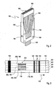
- FIG. 2 For example, one possible embodiment of a cross-sectional transducer 150 is shown in perspective.
- the cross-sectional transducer 150 comprises a frame 182, in which, for example, a plurality of openings 184 may be provided, which in particular allow pinning, screwing or otherwise fixing the cross-sectional transducer 150.
- These openings 184 which may be embodied, for example, as pinning bores or pin bores, are in FIG FIG. 2 shown only schematically and can also be adapted to the respective situation pinning or other assembly techniques and designed differently.
- a plurality of cross-sectional transducers 150 for example by pinning or screwing, can be combined to form cross-sectional converter modules and fixed in the application position 152.
- the frames 182 may be made of aluminum, stainless steel, plastic and / or other materials, for example.
- the cross-sectional transducers 150 are designed such that they have an incoming fiber bundle 146 (in FIG FIG. 2 below) into individual plastic fiber light guides 148.
- the decoupling fiber ends of the individual plastic fiber light guides 148 (in FIG. 2 arranged up to a desired pattern 188 and fixed in this way. Again, this fixation can be done for example by a clamping, gluing or by a kind of fixation.
- the pattern 188 has a line pattern in which, in this embodiment, fifteen fiber ends 186 are preferably at least approximately equidistant from a line.
- each fiber end 186 can have a diameter of approximately 1 mm to 3 mm have.
- Such a line emits, for example, in total a UV light power of about 500 mW to 1500 mW, for example about 1000 mW.
- patterns 188 may also be used, for example matrix patterns with, for example, a rectangular matrix.
- Other embodiments are possible.
- other types of fibers may be used in place of the plastic fiber light guides 148, such as glass fibers.
- an additional beam shaping optics for example with one or more common lenses for all fiber ends 186, or with individual lenses for the Fiber ends 186. In this way, the beam cross sections can be further adapted.
- a plurality of cross-sectional transducers 150 may be combined in the application position 152 to form an application module 190.
- Openings 184 are pinned with pins and / or screwed.
- the openings 184 may be configured, for example, as bores and / or pin bores and / or threaded bores.
- a clamping frame may also be provided to accommodate the individual modules of the cross-sectional transducers 150.
- each of the cross-sectional transducers 150 according to the embodiment FIG. 2 However, the cross-sectional transducers 150 compared to FIG.
- the in FIG. 1 schematically illustrated guide table 154 includes, for example, five rectangular guide grooves, which are matched by their dimensioning in each case on the tape product of the test elements 116.
- This dimensioning can be designed, for example, such that these guide grooves correspond in their width to the individual strips which are produced after the cutting device 125 (in which broad test strips are cut longitudinally, for example, three, five or a different number of narrower strips) and respectively supplied to the guide grooves become.
- an overall positioning uncut test elements 116 through the guide table 154 is possible in principle.
- the tape-shaped test elements 116 can be guided precisely by the guide table 154 and its guide grooves, so that these test elements 116 or test fields arranged thereon and / or other types of radiation-sensitive materials (eg marking fields) can be positioned exactly to the fiber ends 186.
- the individual light sources 144 or the light-emitting diodes 176 accommodated therein can be selectively switched in this way in order to selectively determine specific test elements 116, specific test fields and / or specific marking fields to mark.
- positioning marks may be provided on the test elements 116, which additionally facilitate positioning and / or identification of the test elements 116 for a marking.
- FIG. 3 an embodiment of a test element 116 is shown.
- the test element 116 is designed as a band product in this example, with only one test section of the band being shown.
- the tape of the test element 116 is provided in this embodiment with a plurality of positioning marks 195 which are printed on the endless belt 118, for example in a screen printing process. These positioning marks 195 may be used in the manufacture of the test elements 116 of the positioning of the tape product and / or may serve later, when using the test elements 116 in an analyzer, the correct positioning of the test elements for a sample application and / or for an evaluation of the tests.
- FIG. 3 shows a test element 116 before passing through a cutting device 125 (see FIG. 1 ).
- This uncut tape can then be cut in the cutting device 125, for example along the in FIG. 3 indicated cutting lines 201, so that eventually the actual strip-shaped test elements 116 arise, in which only one of the test fields 196, 198, 200 is arranged side by side.
- the margins without test fields can be discarded.
- band can also be used uncut, so that a test element 116 has three test fields 196, 198, 200 side by side. These could be used, for example, for averaging.
- the test fields 196, 198 and 200 comprise, for example, a detection chemistry which, when a liquid sample, for example a blood sample, is applied, performs a color change in accordance with the presence of an analyte, for example blood glucose.
- This detection chemistry is used in the present embodiment as a radiation-sensitive material 202, which is used as an information carrier for the error information.
- separate tag fields could be used which, regardless of the chemistry of the assay, have radiation sensitive materials.
- FIG. 3 illustrated embodiment of a test element 116 has already passed through the application position 152.
- the radiation source 138 targeted the upper test field 196 in FIG. 3 irradiated, resulting in a visible color change of this test field 196 against the unirradiated test fields 198, 200.
- the upper test field 196 can make targeted unusable for an analysis.
- This color change can be detected, for example, photometrically (eg by a reflection, transmission or color measurement or other types of measurements).
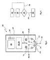
- FIG. 4 an exemplary embodiment of an analytical test device 206 according to the invention is shown symbolically, which operates with test elements 114 marked according to the invention.
- FIG. 5 a possible method for detecting at least one analyte in a sample, which in particular in connection with the in FIG. 4 shown analytical test device can be implemented, which, however, can also be used independently thereof.
- test elements 114 take place in such a way that no test elements 114 marked as defective enter circulation.
- the analytical test device 206 described below or an inventive analytical test device 206 according to another embodiment of the invention merely provides additional assurance that, despite a sorting out of faulty test elements 114, such test elements 114 marked as faulty should circulate during manufacture not be used for tests.
- a selection could also be made only during testing, so that only when tested as defective labeled test elements 114 sorted out, that is not used.
- test elements 114 would possibly be available in this case, but, in particular with a large number of individual test elements 114 on a belt, this might be due to an excess of test elements 114 (ie, an additional number above a nominal number of individual test elements 114) could be compensated.
- the analytical test apparatus 206 in this embodiment has, for example, a tape-shaped test element 114, e.g.
- a tape-shaped test element 114 e.g.
- other types of test elements may be provided, for example strip-shaped test elements, for example in a bar magazine, a drum magazine, a disc magazine or in another type of magazine.
- the analytical test apparatus 206 in this exemplary embodiment has an optical excitation device 208 and an optical detection device 210, which in FIG. 4 are indicated only symbolically.
- this excitation device 208 which may comprise, for example, one or more light sources
- the detection device 210 which may comprise one or more photodiodes, for example, one or more test fields 212 on the test element 114 may be examined for analyte-related color changes in a test position 214
- the analytical test device 206 preferably has a closure 216 in a housing 218 of the analytical test device 206 in this example. This closure 216 releases the test position 214 or a test field 212 located in this test position 214 for the application of a sample 220, which in this exemplary embodiment is preferably a liquid sample.
- the analytical test device 206 furthermore has a drive and evaluation unit 222.
- This control and evaluation unit 222 can, for example, comprise one or more microcomputers and be set up to control the excitation device 208 and / or the detection device 210.
- a transport of the tape-shaped test element 114 can be controlled, so that in each case a transport of a test field 212 in the test position 214 can be controlled.
- controllers and conversely a data exchange are in FIG. 4 symbolically indicated by the double arrow 224.
- the analytical test device 206 preferably has display means, in particular a display 226 and operating elements 228. In this way, the functions of the analytical tester 206 can be controlled, and measurement information can be output.
- a specific test field 212 is controlled by the control and evaluation unit 222 in the test position 214, the shutter 216 is released, and the application of the sample 220 is enabled. Subsequently, by the excitation device 208 and the detection device 210, an optical evaluation of the test field 212, so that, for example, an analyte concentration, in particular a blood sugar concentration can be determined. This can be output, for example, on the display 226.
- an interrogation device 230 which is configured to detect and evaluate markings, which were also applied to the test element 114 and / or the test field 212, for example, according to the method described above.
- This interrogator 230 uses this in FIG. 4 illustrated embodiment, the excitation device 208 and the detection device 210 and a corresponding, for example, software implemented in the drive and evaluation unit 222 interrogation algorithm.
- the interrogator 230 could also be implemented as a separate device separate from the exciter 208 and the detector 210, for example by means of a separate interrogator exciter and / or a separate interrogator (in FIG FIG. 4 not shown). In this way, marked test elements 114 and / or marked test fields 212 can be detected, for example, in which a coloring of the test fields 212 is detected.
- a specific test element 114 and / or a specific test field 212 is initially provided in the test position 214. This is in FIG. 5 symbolically denoted by the reference numeral 232. Subsequently, by means of the interrogation device 230 it is queried whether the test field 212 and / or the test element 114 is provided with a marking, and / or the error information contained in the marking is read out (step 234). This information can be evaluated, for example, in the control and evaluation unit 222. Thereafter, a decision step 236 may be performed in which it is decided whether the test field 212 and / or the test element 114 is faulty (branch 238 or error-free (branch 240 in FIG FIG. 5 ).
- a warning can be output to a user, for example in the form of a visual warning (eg on the display 226) and / or an audible warning.
- a new test field 212 and / or test element 114 is provided.
- a fresh, previously unused test field 212 can be moved to the test position 214 become.
- the method steps described so far are carried out so that during the implementation of these method steps, the closure 216 is closed, so that an application of the sample 220 is not yet possible.
- a measurement 242 can then be carried out, in which case the detection of at least one analyte in the sample 220 takes place.
- the shutter 216 may be released and / or the excitation device 208 and the detection device 210 may be activated, for example to perform an analyte-related color change.
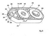
- the tape cassette 244 comprises a test element 114 in the form of an analytical test tape 246.
- the analytical test tape 246 is removable from a supply reel 248 and wound on a take-up reel 252 via a tape guide 250.
- a test band section 254 of the analytical test strip 246 is stretched flat at a measuring point 256 above a planar support frame 258 to allow frontal application of the liquid sample 220, for example in the form of body fluid (eg blood or tissue fluid), and a precise back-side reflectometric measurement allow.
- body fluid eg blood or tissue fluid
- the test tape 246 has a translucent carrier tape 260 which, for example, the endless belt 118 in FIG. 3 (in cut form) may correspond.
- On the front of this carrier tape 260 are, for example, analogous to FIG. 3 above, test fields applied label-like, which, for example, the test fields 196, 198 and 200 in FIG. 3 can correspond.
- These test fields 262 may include, for example, dry chemicals that respond to the analyte (eg, glucose) in the applied liquid sample 220 (eg, blood fluid) and, when backlit, result in a measurable change in light reflectance.
- the carrier tape 260 may have a 5 mm wide and about 10 micron thick film, to which a detection film of 50 microns thickness is partially applied front side (for example, aufetikettiert).
- measurement light is irradiated and reflected back over a measurement opening 264 bordered by the support frame 258, without the need for optical elements such as lenses, filters or material-filled windows to be present within the opening area.
- the measuring opening 264 can be framed by an aperture if required (in FIG FIG. 6 not shown). This allows a defined back focusing of an optical measuring unit (not contained in the tape cassette 244) of the analytical test apparatus 206 onto the test tape section 254, which is exposed flat above the measuring opening 264.
- a belt drive of the analytical testing device 206 engaging in a hub 266 of the take-up reel 252 enables the pre-winding of the test tape 246.
- friction occurs on the supply reel 248 and in the area of the tape guide 250 (there, in particular at a throat seal 268) generates restraining forces of about 2 Newton, so that the test tape 246 is sufficiently tensioned to ensure a flat overlay on the support frame 258.
- the tape guide 250 can be formed, for example, by an injection-molded part made of polypropylene, which at the same time can form a carrier body for the coils 248, 252.
- a lid member 270 is provided, which has a breakthrough on a tapered narrow side wall for an easily accessible exposure of the support frame 258.
- test element 114 which is here in cassette form, either the entire analytical test tape 246 may be considered, or individual test tape sections 254 (eg, test tape sections each having a test field 262) may be considered as such test elements 114.
- the test tape 246 may be marked as a whole, or alternatively or additionally, a marking of individual test tape sections 254 may also take place by means of the method proposed above. If a separate device is used for the reading of error marks, this can be integrated, for example, in the said optical measuring unit of the analytical test device 206.
- the excitation device 208 and the detection device 210 of the analytical test device 206 can also assume the function of reading the error markers in addition to the analysis function. Combinations of these two possibilities are conceivable, for example in the context of a separate light source for the reading of the Error marking, however, the detection device 210 at the same time takes over the task of error reading.
- the analytical test device 206 may be configured such that it is queried before performing a measurement, whether the currently located in the measuring point 256 test tape section 254 is faulty. If this is the case, by appropriate operation of the coils 248, 252, for example, on the next test tape portion 254 optzulespult, and repeats the procedure, for example using the above with reference to FIG. 5 described method.
Landscapes
- Health & Medical Sciences (AREA)
- Life Sciences & Earth Sciences (AREA)
- Engineering & Computer Science (AREA)
- Physics & Mathematics (AREA)
- Biomedical Technology (AREA)
- Chemical & Material Sciences (AREA)
- Analytical Chemistry (AREA)
- Biochemistry (AREA)
- General Health & Medical Sciences (AREA)
- General Physics & Mathematics (AREA)
- Immunology (AREA)
- Pathology (AREA)
- Urology & Nephrology (AREA)
- Food Science & Technology (AREA)
- Optics & Photonics (AREA)
- Biophysics (AREA)
- Hematology (AREA)
- Molecular Biology (AREA)
- Medicinal Chemistry (AREA)
- High Energy & Nuclear Physics (AREA)
- General Engineering & Computer Science (AREA)
- Investigating, Analyzing Materials By Fluorescence Or Luminescence (AREA)
- Apparatuses And Processes For Manufacturing Resistors (AREA)
- Apparatus Associated With Microorganisms And Enzymes (AREA)
- Automatic Analysis And Handling Materials Therefor (AREA)
- Investigating Or Analysing Materials By The Use Of Chemical Reactions (AREA)
Priority Applications (9)
| Application Number | Priority Date | Filing Date | Title |
|---|---|---|---|
| AT07116749T ATE431932T1 (de) | 2007-09-19 | 2007-09-19 | Markierungsverfahren zur ausschussmarkierung von testelementen |
| EP07116749A EP2040079B1 (de) | 2007-09-19 | 2007-09-19 | Markierungsverfahren zur Ausschussmarkierung von Testelementen |
| DE502007000757T DE502007000757D1 (de) | 2007-09-19 | 2007-09-19 | Markierungsverfahren zur Ausschussmarkierung von Testelementen |
| CA2639480A CA2639480C (en) | 2007-09-19 | 2008-09-11 | Marking method for the reject marking of test elements |
| US12/212,874 US8618511B2 (en) | 2007-09-19 | 2008-09-18 | Marking method for the reject marking of test elements |
| JP2008238995A JP5191848B2 (ja) | 2007-09-19 | 2008-09-18 | テストエレメントの不合格品マーキングのマーキング方法、マーキング装置、テストエレメントを作製する製造装置、および分析テスト装置 |
| CN2008101497209A CN101430328B (zh) | 2007-09-19 | 2008-09-19 | 测试元件的不合格标记的标记方法 |
| HK09106689.4A HK1128762B (en) | 2007-09-19 | 2009-07-22 | Marking method for the reject marking of test elements |
| US14/104,614 US10535442B2 (en) | 2007-09-19 | 2013-12-12 | Marking method for the reject marking of test elements |
Applications Claiming Priority (1)
| Application Number | Priority Date | Filing Date | Title |
|---|---|---|---|
| EP07116749A EP2040079B1 (de) | 2007-09-19 | 2007-09-19 | Markierungsverfahren zur Ausschussmarkierung von Testelementen |
Publications (2)
| Publication Number | Publication Date |
|---|---|
| EP2040079A1 EP2040079A1 (de) | 2009-03-25 |
| EP2040079B1 true EP2040079B1 (de) | 2009-05-20 |
Family
ID=38952104
Family Applications (1)
| Application Number | Title | Priority Date | Filing Date |
|---|---|---|---|
| EP07116749A Active EP2040079B1 (de) | 2007-09-19 | 2007-09-19 | Markierungsverfahren zur Ausschussmarkierung von Testelementen |
Country Status (7)
| Country | Link |
|---|---|
| US (2) | US8618511B2 (enExample) |
| EP (1) | EP2040079B1 (enExample) |
| JP (1) | JP5191848B2 (enExample) |
| CN (1) | CN101430328B (enExample) |
| AT (1) | ATE431932T1 (enExample) |
| CA (1) | CA2639480C (enExample) |
| DE (1) | DE502007000757D1 (enExample) |
Cited By (1)
| Publication number | Priority date | Publication date | Assignee | Title |
|---|---|---|---|---|
| US10180248B2 (en) | 2015-09-02 | 2019-01-15 | ProPhotonix Limited | LED lamp with sensing capabilities |
Families Citing this family (13)
| Publication number | Priority date | Publication date | Assignee | Title |
|---|---|---|---|---|
| EP2228658A1 (de) * | 2009-03-13 | 2010-09-15 | Roche Diagnostics GmbH | Verfahren zur Herstellung eines analytischen Verbrauchsmittels |
| CA3095919A1 (en) * | 2009-07-27 | 2011-02-10 | Meso Scale Technologies, Llc | Assay information management methods and devices |
| EP2506014B1 (en) | 2011-03-30 | 2014-08-06 | Kabushiki Kaisha Toshiba | Measuring system using optical waveguide, measuring device, measuring method, optical waveguide type sensor chip, and magnetic fine particle |
| US9207181B2 (en) * | 2012-03-01 | 2015-12-08 | Quidel Corporation | System and apparatus for point-of-care diagnostics |
| EP2820420B1 (en) | 2012-03-01 | 2017-08-16 | Quidel Corporation | Interactive test device and apparatus with timing mechanism |
| US9951472B2 (en) | 2014-04-15 | 2018-04-24 | Gpcp Ip Holdings Llc | Methods and apparatuses for controlling a manufacturing line used to convert a paper web into paper products by reading marks on the paper web |
| DE102014113159A1 (de) * | 2014-09-12 | 2016-03-17 | Scherdel Innotec Forschungs- Und Entwicklungs-Gmbh | Vorrichtung und Verfahren zum Herstellen eines Federdrahts, Vorrichtung und Verfahren zum Markieren eines Federdrahts, Vorrichtung und Verfahren zum Herstellen von Federn aus einem Federdraht sowie Federdraht |
| AT518369B1 (de) * | 2016-02-11 | 2023-06-15 | Zkw Group Gmbh | Verfahren und ICT-Einrichtung zum Überprüfen von zumindest zwei LEDs enthaltenden Modulen einer Beleuchtungseinrichtung |
| JP6539371B1 (ja) * | 2018-03-14 | 2019-07-03 | Ckd株式会社 | 検査装置、ptp包装機、及び、検査方法 |
| CN110001221B (zh) * | 2019-04-11 | 2021-04-02 | 淮安信息职业技术学院 | 喷码位置偏移的检测方法及装置 |
| CN110579171A (zh) * | 2019-08-22 | 2019-12-17 | 广州昱奕智能自动化设备有限公司 | 一种零件加工检测监控装置及系统 |
| WO2024005695A1 (en) * | 2022-06-29 | 2024-01-04 | Delaval Holding Ab | A quality determining arrangement and a quality check method |
| CN115219685A (zh) * | 2022-07-18 | 2022-10-21 | 马鞍山钢铁股份有限公司 | 一种同时确定多个影响带钢表面质量的泄漏辐射管的方法 |
Family Cites Families (34)
| Publication number | Priority date | Publication date | Assignee | Title |
|---|---|---|---|---|
| DE3326689A1 (de) | 1983-07-23 | 1985-01-31 | Boehringer Mannheim Gmbh, 6800 Mannheim | Verfahren und vorrichtung zur herstellung eines teststreifens |
| JPS6191571A (ja) * | 1984-10-11 | 1986-05-09 | Kyoto Daiichi Kagaku:Kk | 試験片を用いる連続自動分析方法及び装置 |
| JPH0750095B2 (ja) * | 1987-02-10 | 1995-05-31 | 富士写真フイルム株式会社 | 化学分析スライドの連続製造装置 |
| US4865198A (en) | 1988-02-01 | 1989-09-12 | R. J. Reynolds Tobacco Company | Overwrapped package with tamper indicating means |
| US5286362A (en) | 1990-02-03 | 1994-02-15 | Boehringer Mannheim Gmbh | Method and sensor electrode system for the electrochemical determination of an analyte or an oxidoreductase as well as the use of suitable compounds therefor |
| CA2050677C (en) | 1990-09-06 | 2003-04-08 | Ernest J. Kiser | Visual blood glucose concentration test strip |
| US5390671A (en) | 1994-03-15 | 1995-02-21 | Minimed Inc. | Transcutaneous sensor insertion set |
| US5708247A (en) * | 1996-02-14 | 1998-01-13 | Selfcare, Inc. | Disposable glucose test strips, and methods and compositions for making same |
| US6168957B1 (en) * | 1997-06-25 | 2001-01-02 | Lifescan, Inc. | Diagnostic test strip having on-strip calibration |
| AU768312B2 (en) * | 1998-11-30 | 2003-12-11 | Abbott Laboratories | Analyte test instrument having improved calibration and communication processes |
| US6045567A (en) * | 1999-02-23 | 2000-04-04 | Lifescan Inc. | Lancing device causing reduced pain |
| JP2001055537A (ja) | 1999-08-19 | 2001-02-27 | Dainippon Ink & Chem Inc | レーザマーキング用水性塗料及び炭酸ガスレーザマーキング方法 |
| JP2001183558A (ja) | 1999-12-24 | 2001-07-06 | Sumitomo Electric Ind Ltd | 光ファイバ及び光ファイバの製造方法 |
| US7373197B2 (en) * | 2000-03-03 | 2008-05-13 | Intramedical Imaging, Llc | Methods and devices to expand applications of intraoperative radiation probes |
| GB0005564D0 (en) * | 2000-03-08 | 2000-05-03 | Inverness Medical Ltd | Measurjement of substances in liquid |
| JP2002066770A (ja) | 2000-08-29 | 2002-03-05 | Nippon Laser & Electronics Lab | レーザマーキング装置 |
| JP3913680B2 (ja) * | 2001-03-16 | 2007-05-09 | データレイズ・リミテッド | レーザマーキング用組成物 |
| US6557446B2 (en) * | 2001-03-26 | 2003-05-06 | Kinematic Automation, Inc. | Apparatus for cutting and sorting diagnostic strips |
| US20030207441A1 (en) * | 2002-05-01 | 2003-11-06 | Eyster Curt R. | Devices and methods for analyte concentration determination |
| GB2389419B (en) * | 2002-06-05 | 2006-02-22 | Diabetes Diagnostics Inc | Analyte testing device |
| US20040048359A1 (en) * | 2002-07-12 | 2004-03-11 | Schmeling William R. | Test strips moveable by magnetic fields |
| US7731900B2 (en) * | 2002-11-26 | 2010-06-08 | Roche Diagnostics Operations, Inc. | Body fluid testing device |
| JP2005056608A (ja) | 2003-08-06 | 2005-03-03 | Tokyo Iken Kk | 光照射装置及びこの光照射装置を使用する光線治療器 |
| US20050102976A1 (en) * | 2003-11-19 | 2005-05-19 | Stroup David K. | Diagnostic kit flexible assembly system and method of using the same |
| JP2006000865A (ja) | 2004-06-15 | 2006-01-05 | Mitsubishi Materials Corp | マーキング方法 |
| US7556723B2 (en) * | 2004-06-18 | 2009-07-07 | Roche Diagnostics Operations, Inc. | Electrode design for biosensor |
| US7601299B2 (en) * | 2004-06-18 | 2009-10-13 | Roche Diagnostics Operations, Inc. | System and method for coding information on a biosensor test strip |
| US20060006574A1 (en) * | 2004-06-29 | 2006-01-12 | Lang David K | Apparatus for the manufacture of medical devices |
| WO2007022215A2 (en) * | 2005-08-16 | 2007-02-22 | Home Diagnostics, Inc. | Method for test strip manufacturing and analysis |
| DE502005010516D1 (de) * | 2005-10-01 | 2010-12-23 | Roche Diagnostics Gmbh | Analytisches System und Verfahren zu dessen Betrieb |
| EP1826705A1 (de) * | 2006-02-25 | 2007-08-29 | F.Hoffmann-La Roche Ag | Analytisches Verbrauchsmittel und Anordnung zum Auslesen von Informationen |
| US7474390B2 (en) * | 2006-05-26 | 2009-01-06 | Lifescan Scotland Limited | Test strip with permutative grey scale calibration pattern |
| US7798414B2 (en) * | 2006-07-21 | 2010-09-21 | Isp Investments Inc. | Human and scanner readable radiation exposure indicator with reactive barcode |
| US7364335B2 (en) * | 2006-08-04 | 2008-04-29 | Illumination Technologies, Inc. | Modular optical light line unit |
-
2007
- 2007-09-19 DE DE502007000757T patent/DE502007000757D1/de active Active
- 2007-09-19 EP EP07116749A patent/EP2040079B1/de active Active
- 2007-09-19 AT AT07116749T patent/ATE431932T1/de not_active IP Right Cessation
-
2008
- 2008-09-11 CA CA2639480A patent/CA2639480C/en active Active
- 2008-09-18 JP JP2008238995A patent/JP5191848B2/ja active Active
- 2008-09-18 US US12/212,874 patent/US8618511B2/en active Active
- 2008-09-19 CN CN2008101497209A patent/CN101430328B/zh active Active
-
2013
- 2013-12-12 US US14/104,614 patent/US10535442B2/en active Active
Cited By (1)
| Publication number | Priority date | Publication date | Assignee | Title |
|---|---|---|---|---|
| US10180248B2 (en) | 2015-09-02 | 2019-01-15 | ProPhotonix Limited | LED lamp with sensing capabilities |
Also Published As
| Publication number | Publication date |
|---|---|
| CN101430328B (zh) | 2013-06-12 |
| US10535442B2 (en) | 2020-01-14 |
| EP2040079A1 (de) | 2009-03-25 |
| DE502007000757D1 (de) | 2009-07-02 |
| ATE431932T1 (de) | 2009-06-15 |
| US20090090874A1 (en) | 2009-04-09 |
| JP2009139364A (ja) | 2009-06-25 |
| JP5191848B2 (ja) | 2013-05-08 |
| CA2639480C (en) | 2016-03-22 |
| US20140096368A1 (en) | 2014-04-10 |
| US8618511B2 (en) | 2013-12-31 |
| HK1128762A1 (en) | 2009-11-06 |
| CA2639480A1 (en) | 2009-03-19 |
| CN101430328A (zh) | 2009-05-13 |
Similar Documents
| Publication | Publication Date | Title |
|---|---|---|
| EP2040079B1 (de) | Markierungsverfahren zur Ausschussmarkierung von Testelementen | |
| DE3642209C2 (enExample) | ||
| EP2399119B1 (de) | Testverfahren und Testvorrichtung zur Untersuchung einer Körperflüssigkeit | |
| EP1736774B1 (de) | Analysesystem zur Analyse einer Probe auf einem analytischen Testelement | |
| EP2317909B1 (de) | Medizinisches system mit kompaktem barcodeleser für verbrauchsartikel | |
| DE1673340A1 (de) | Chemische Analysierungseinrichtung | |
| EP0819943A2 (de) | Analysesystem mit Mitteln zur Erkennung von Unterdosierungen | |
| DE1673341A1 (de) | Chemische Analysierungseinrichtung | |
| EP1716418A2 (de) | Vorrichtung und verfahren zur optischen auswertung von teststreifen | |
| EP1972942A1 (de) | Verfahren zur Verhinderung des mehrfachen Gebrauchs von Einmalartikeln in Analysegeräten | |
| EP2406638B1 (de) | Verfahren und vorrichtung zur herstellung eines analytischen verbrauchsmittels | |
| DE102018111033A1 (de) | Transmissionsvorrichtung zur Untersuchung von Proben in Kavitäten einer Mikrotiterplatte und Verfahren zum Untersuchen von Proben in Kavitäten einer Mikrotiterplatte mittels Transmission | |
| DE102008056583B4 (de) | Verfahren und Vorrichtung zur Feststellung der Reagenzienqualität | |
| DE19628562A1 (de) | Analysesystem mit Mitteln zur Erkennung von Unterdosierungen | |
| EP2009600B1 (de) | Verfahren zur identifizierung eines transparenten objekts anhand seines absorptionsspektrums | |
| EP3649501A1 (de) | Verfahren zum untersuchen einer flüssigkeit, die wenigstens eine zelle und/oder wenigstens ein partikel enthält | |
| DE3717914A1 (de) | Chemische analyseeinrichtung | |
| EP3418723B1 (de) | Pipettiervorrichtung mit mehrkanaligem verteiler zur simultanen extinktionsbestimmung | |
| AT525192A1 (de) | Mikrofluidischer chip | |
| HK1128762B (en) | Marking method for the reject marking of test elements |
Legal Events
| Date | Code | Title | Description |
|---|---|---|---|
| GRAP | Despatch of communication of intention to grant a patent |
Free format text: ORIGINAL CODE: EPIDOSNIGR1 |
|
| GRAS | Grant fee paid |
Free format text: ORIGINAL CODE: EPIDOSNIGR3 |
|
| PUAI | Public reference made under article 153(3) epc to a published international application that has entered the european phase |
Free format text: ORIGINAL CODE: 0009012 |
|
| 17P | Request for examination filed |
Effective date: 20080516 |
|
| AK | Designated contracting states |
Kind code of ref document: A1 Designated state(s): AT BE BG CH CY CZ DE DK EE ES FI FR GB GR HU IE IS IT LI LT LU LV MC MT NL PL PT RO SE SI SK TR |
|
| AX | Request for extension of the european patent |
Extension state: AL BA HR MK RS |
|
| GRAA | (expected) grant |
Free format text: ORIGINAL CODE: 0009210 |
|
| AK | Designated contracting states |
Kind code of ref document: B1 Designated state(s): AT BE BG CH CY CZ DE DK EE ES FI FR GB GR HU IE IS IT LI LT LU LV MC MT NL PL PT RO SE SI SK TR |
|
| REG | Reference to a national code |
Ref country code: GB Ref legal event code: FG4D Free format text: NOT ENGLISH |
|
| REG | Reference to a national code |
Ref country code: CH Ref legal event code: EP |
|
| REG | Reference to a national code |
Ref country code: IE Ref legal event code: FG4D Free format text: LANGUAGE OF EP DOCUMENT: GERMAN |
|
| REF | Corresponds to: |
Ref document number: 502007000757 Country of ref document: DE Date of ref document: 20090702 Kind code of ref document: P |
|
| PG25 | Lapsed in a contracting state [announced via postgrant information from national office to epo] |
Ref country code: LT Free format text: LAPSE BECAUSE OF FAILURE TO SUBMIT A TRANSLATION OF THE DESCRIPTION OR TO PAY THE FEE WITHIN THE PRESCRIBED TIME-LIMIT Effective date: 20090520 Ref country code: PT Free format text: LAPSE BECAUSE OF FAILURE TO SUBMIT A TRANSLATION OF THE DESCRIPTION OR TO PAY THE FEE WITHIN THE PRESCRIBED TIME-LIMIT Effective date: 20090920 Ref country code: FI Free format text: LAPSE BECAUSE OF FAILURE TO SUBMIT A TRANSLATION OF THE DESCRIPTION OR TO PAY THE FEE WITHIN THE PRESCRIBED TIME-LIMIT Effective date: 20090520 Ref country code: ES Free format text: LAPSE BECAUSE OF FAILURE TO SUBMIT A TRANSLATION OF THE DESCRIPTION OR TO PAY THE FEE WITHIN THE PRESCRIBED TIME-LIMIT Effective date: 20090831 |
|
| NLV1 | Nl: lapsed or annulled due to failure to fulfill the requirements of art. 29p and 29m of the patents act | ||
| PG25 | Lapsed in a contracting state [announced via postgrant information from national office to epo] |
Ref country code: PL Free format text: LAPSE BECAUSE OF FAILURE TO SUBMIT A TRANSLATION OF THE DESCRIPTION OR TO PAY THE FEE WITHIN THE PRESCRIBED TIME-LIMIT Effective date: 20090520 Ref country code: IS Free format text: LAPSE BECAUSE OF FAILURE TO SUBMIT A TRANSLATION OF THE DESCRIPTION OR TO PAY THE FEE WITHIN THE PRESCRIBED TIME-LIMIT Effective date: 20090920 Ref country code: SE Free format text: LAPSE BECAUSE OF FAILURE TO SUBMIT A TRANSLATION OF THE DESCRIPTION OR TO PAY THE FEE WITHIN THE PRESCRIBED TIME-LIMIT Effective date: 20090820 Ref country code: SI Free format text: LAPSE BECAUSE OF FAILURE TO SUBMIT A TRANSLATION OF THE DESCRIPTION OR TO PAY THE FEE WITHIN THE PRESCRIBED TIME-LIMIT Effective date: 20090520 Ref country code: NL Free format text: LAPSE BECAUSE OF FAILURE TO SUBMIT A TRANSLATION OF THE DESCRIPTION OR TO PAY THE FEE WITHIN THE PRESCRIBED TIME-LIMIT Effective date: 20090520 Ref country code: LV Free format text: LAPSE BECAUSE OF FAILURE TO SUBMIT A TRANSLATION OF THE DESCRIPTION OR TO PAY THE FEE WITHIN THE PRESCRIBED TIME-LIMIT Effective date: 20090520 |
|
| AKX | Designation fees paid |
Designated state(s): AT BE BG CH CY CZ DE DK EE ES FI FR GB GR HU IE IS IT LI LT LU LV MC MT NL PL PT RO SE SI SK TR |
|
| REG | Reference to a national code |
Ref country code: IE Ref legal event code: FD4D |
|
| PG25 | Lapsed in a contracting state [announced via postgrant information from national office to epo] |
Ref country code: EE Free format text: LAPSE BECAUSE OF FAILURE TO SUBMIT A TRANSLATION OF THE DESCRIPTION OR TO PAY THE FEE WITHIN THE PRESCRIBED TIME-LIMIT Effective date: 20090520 Ref country code: IE Free format text: LAPSE BECAUSE OF FAILURE TO SUBMIT A TRANSLATION OF THE DESCRIPTION OR TO PAY THE FEE WITHIN THE PRESCRIBED TIME-LIMIT Effective date: 20090520 Ref country code: DK Free format text: LAPSE BECAUSE OF FAILURE TO SUBMIT A TRANSLATION OF THE DESCRIPTION OR TO PAY THE FEE WITHIN THE PRESCRIBED TIME-LIMIT Effective date: 20090520 Ref country code: CZ Free format text: LAPSE BECAUSE OF FAILURE TO SUBMIT A TRANSLATION OF THE DESCRIPTION OR TO PAY THE FEE WITHIN THE PRESCRIBED TIME-LIMIT Effective date: 20090520 Ref country code: RO Free format text: LAPSE BECAUSE OF FAILURE TO SUBMIT A TRANSLATION OF THE DESCRIPTION OR TO PAY THE FEE WITHIN THE PRESCRIBED TIME-LIMIT Effective date: 20090520 |
|
| PG25 | Lapsed in a contracting state [announced via postgrant information from national office to epo] |
Ref country code: SK Free format text: LAPSE BECAUSE OF FAILURE TO SUBMIT A TRANSLATION OF THE DESCRIPTION OR TO PAY THE FEE WITHIN THE PRESCRIBED TIME-LIMIT Effective date: 20090520 |
|
| PLBE | No opposition filed within time limit |
Free format text: ORIGINAL CODE: 0009261 |
|
| STAA | Information on the status of an ep patent application or granted ep patent |
Free format text: STATUS: NO OPPOSITION FILED WITHIN TIME LIMIT |
|
| BERE | Be: lapsed |
Owner name: F. HOFFMANN-LA ROCHE A.G. Effective date: 20090930 Owner name: ROCHE DIAGNOSTICS G.M.B.H. Effective date: 20090930 |
|
| PG25 | Lapsed in a contracting state [announced via postgrant information from national office to epo] |
Ref country code: BG Free format text: LAPSE BECAUSE OF FAILURE TO SUBMIT A TRANSLATION OF THE DESCRIPTION OR TO PAY THE FEE WITHIN THE PRESCRIBED TIME-LIMIT Effective date: 20090820 |
|
| 26N | No opposition filed |
Effective date: 20100223 |
|
| PG25 | Lapsed in a contracting state [announced via postgrant information from national office to epo] |
Ref country code: MC Free format text: LAPSE BECAUSE OF NON-PAYMENT OF DUE FEES Effective date: 20090930 |
|
| PG25 | Lapsed in a contracting state [announced via postgrant information from national office to epo] |
Ref country code: BE Free format text: LAPSE BECAUSE OF NON-PAYMENT OF DUE FEES Effective date: 20090930 |
|
| PG25 | Lapsed in a contracting state [announced via postgrant information from national office to epo] |
Ref country code: GR Free format text: LAPSE BECAUSE OF FAILURE TO SUBMIT A TRANSLATION OF THE DESCRIPTION OR TO PAY THE FEE WITHIN THE PRESCRIBED TIME-LIMIT Effective date: 20090821 |
|
| PG25 | Lapsed in a contracting state [announced via postgrant information from national office to epo] |
Ref country code: AT Free format text: LAPSE BECAUSE OF NON-PAYMENT OF DUE FEES Effective date: 20090919 |
|
| PG25 | Lapsed in a contracting state [announced via postgrant information from national office to epo] |
Ref country code: IT Free format text: LAPSE BECAUSE OF FAILURE TO SUBMIT A TRANSLATION OF THE DESCRIPTION OR TO PAY THE FEE WITHIN THE PRESCRIBED TIME-LIMIT Effective date: 20090520 |
|
| PG25 | Lapsed in a contracting state [announced via postgrant information from national office to epo] |
Ref country code: LU Free format text: LAPSE BECAUSE OF NON-PAYMENT OF DUE FEES Effective date: 20090919 Ref country code: MT Free format text: LAPSE BECAUSE OF FAILURE TO SUBMIT A TRANSLATION OF THE DESCRIPTION OR TO PAY THE FEE WITHIN THE PRESCRIBED TIME-LIMIT Effective date: 20090520 |
|
| PG25 | Lapsed in a contracting state [announced via postgrant information from national office to epo] |
Ref country code: HU Free format text: LAPSE BECAUSE OF FAILURE TO SUBMIT A TRANSLATION OF THE DESCRIPTION OR TO PAY THE FEE WITHIN THE PRESCRIBED TIME-LIMIT Effective date: 20091121 |
|
| PG25 | Lapsed in a contracting state [announced via postgrant information from national office to epo] |
Ref country code: TR Free format text: LAPSE BECAUSE OF FAILURE TO SUBMIT A TRANSLATION OF THE DESCRIPTION OR TO PAY THE FEE WITHIN THE PRESCRIBED TIME-LIMIT Effective date: 20090520 |
|
| PG25 | Lapsed in a contracting state [announced via postgrant information from national office to epo] |
Ref country code: CY Free format text: LAPSE BECAUSE OF FAILURE TO SUBMIT A TRANSLATION OF THE DESCRIPTION OR TO PAY THE FEE WITHIN THE PRESCRIBED TIME-LIMIT Effective date: 20090520 |
|
| REG | Reference to a national code |
Ref country code: CH Ref legal event code: PL |
|
| PG25 | Lapsed in a contracting state [announced via postgrant information from national office to epo] |
Ref country code: CH Free format text: LAPSE BECAUSE OF NON-PAYMENT OF DUE FEES Effective date: 20110930 Ref country code: LI Free format text: LAPSE BECAUSE OF NON-PAYMENT OF DUE FEES Effective date: 20110930 |
|
| REG | Reference to a national code |
Ref country code: DE Ref legal event code: R081 Ref document number: 502007000757 Country of ref document: DE Owner name: ROCHE DIABETES CARE GMBH, DE Free format text: FORMER OWNER: ROCHE DIAGNOSTICS GMBH, 68305 MANNHEIM, DE |
|
| REG | Reference to a national code |
Ref country code: FR Ref legal event code: PLFP Year of fee payment: 10 |
|
| REG | Reference to a national code |
Ref country code: FR Ref legal event code: PLFP Year of fee payment: 11 |
|
| REG | Reference to a national code |
Ref country code: FR Ref legal event code: PLFP Year of fee payment: 12 |
|
| PGFP | Annual fee paid to national office [announced via postgrant information from national office to epo] |
Ref country code: DE Payment date: 20250820 Year of fee payment: 19 |
|
| PGFP | Annual fee paid to national office [announced via postgrant information from national office to epo] |
Ref country code: GB Payment date: 20250820 Year of fee payment: 19 |
|
| PGFP | Annual fee paid to national office [announced via postgrant information from national office to epo] |
Ref country code: FR Payment date: 20250820 Year of fee payment: 19 |