EP2039618A1 - Anordnung mit einem Stapelbehälter und einer Kennzeichnungseinrichtung - Google Patents
Anordnung mit einem Stapelbehälter und einer Kennzeichnungseinrichtung Download PDFInfo
- Publication number
- EP2039618A1 EP2039618A1 EP08014172A EP08014172A EP2039618A1 EP 2039618 A1 EP2039618 A1 EP 2039618A1 EP 08014172 A EP08014172 A EP 08014172A EP 08014172 A EP08014172 A EP 08014172A EP 2039618 A1 EP2039618 A1 EP 2039618A1
- Authority
- EP
- European Patent Office
- Prior art keywords
- stacking
- collar
- container
- side wall
- arrangement according
- Prior art date
- Legal status (The legal status is an assumption and is not a legal conclusion. Google has not performed a legal analysis and makes no representation as to the accuracy of the status listed.)
- Granted
Links
Images
Classifications
-
- B—PERFORMING OPERATIONS; TRANSPORTING
- B65—CONVEYING; PACKING; STORING; HANDLING THIN OR FILAMENTARY MATERIAL
- B65D—CONTAINERS FOR STORAGE OR TRANSPORT OF ARTICLES OR MATERIALS, e.g. BAGS, BARRELS, BOTTLES, BOXES, CANS, CARTONS, CRATES, DRUMS, JARS, TANKS, HOPPERS, FORWARDING CONTAINERS; ACCESSORIES, CLOSURES, OR FITTINGS THEREFOR; PACKAGING ELEMENTS; PACKAGES
- B65D25/00—Details of other kinds or types of rigid or semi-rigid containers
- B65D25/20—External fittings
- B65D25/205—Means for the attachment of labels, cards, coupons or the like
Definitions
- the invention describes an arrangement with a stack container and a marking device.
- stacking containers are used for a wide variety of storage and transport tasks.
- just in the stacked state of a plurality of these stack container marking the contents of the individual stack container to overview essential.
- a stacking container is known with an integrally formed with the stacking container handle bar, which has a recess formed suitably formed in this handle, there to arrange a label well readable and removable.
- the stacking container handle bar which has a recess formed suitably formed in this handle, there to arrange a label well readable and removable.
- a stack container according to the prior art is known. This has a bottom, edges and at the top and bottom each have a stacking collar and in the embodiment disclosed here an additional cover.
- the invention has for its object to provide an arrangement of a stacking container and a marking device, which is inexpensive to produce, the connection between the stack container and labeling device is reversible and the stackability of the stack container is not limited.
- the starting point of the arrangement according to the invention is a stacking container according to the prior art.
- This stacking container has a bottom and a preferably circumferential side wall, which in itself adjoins the sides of the bottom.
- This side wall, as well as the floor, can be designed completely or with recesses which exemplarily form a grid.
- the stacking container On the closed side, the bottom, the stacking container has a lower stacking collar, which is arranged as a possibility of anti-slip in the stack, preferably in the direction of the upper Stapelbundes spaced from the plane defined by the outer major surface of the soil.
- the stacking container has at least one reinforcing collar.
- the surface normals of the stacking collars and the at least one reinforcing collar are in the same direction as the surface normals of the bottom and orthogonal to the surface normals of the edges.
- the stacking container consists of a thermoplastic material with a respective thickness of the side wall and the bottom between 1 mm and 10 mm.
- the marking device is formed with a marking surface and at least one adjoining retaining foot.
- the marking device is configured as a U-shaped metal molded body, preferably of stainless steel sheet, and has at least one clamping device formed by at least one cutout.
- the marking surface of the marking device is arranged parallel to the side wall of the stacking container, wherein the holding foot comprises the upper stacking collar and wherein it is preferred if a partial section of the holding foot extends into the inner region of the stacking container and bears against the inner wall of the associated side wall.
- the at least one clamping device is deformed along an associated bending edge and protrudes suitably into the free area between the upper stacking collar and a reinforcing collar or into the area between a reinforcing collar and the lower stacking collar.
- An advantage of this arrangement according to the invention is that a limited only by the limits of the stack container, otherwise arbitrarily large Labeling surface for marking the stacking container or its contents is available. It is also advantageous that the stackability of the stacking container is not impaired and the connection between the stacking container and the marking device can be quickly released and restored. Ultimately, the marking device is inexpensive to produce.
- the arrangement can advantageously be supplemented by a cover according to the above cited prior art.
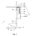
- Fig. 1 shows a section of the arrangement according to the invention in a sectional view.
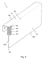
- Fig. 2 shows a three-dimensional view of a first embodiment of the marking device according to Fig. 1 the inventive arrangement.
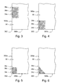
- Fig. 3 shows the embodiment of the marking device according to Fig. 2 in plan view.
- the 4 to 6 show further embodiments of the marking device of the arrangement according to the invention.
- Fig. 1 shows a section of the arrangement (1) according to the invention in a sectional view. Shown here is a side wall (22) and a portion of the bottom (20) of a first and a second stack container (2) according to the prior art, said stack container (2) made of a thermoplastic material having a thickness of the side wall (22) and of the bottom (20) between 1 mm and 10mm.
- the side wall (22) of the stacking container (2) has on the open, the bottom (20) opposite side of the stacking container (2) an upper stacking collar (26) with the side wall (22) the upper end of the stacking container (2 ).
- This upper stacking collar (26) serves as an abutment for a lower stacking collar (24) of a second stacking container, which is arranged on the first stacking container, stacked.
- This lower stacking collar (24) is disposed on the closed side, the bottom (20), and spaced from the plane of the stacking containers (2) defined by the outer major surface (200) of the bottom (20). Between the upper (26) and lower (24) stacking bundles, the stacking container (2) has at least one reinforcing collar (28).
- the surface normals of the stacking collars (24, 26) and the reinforcing collar (28) point in the same direction as the surface normals of the bottom (20) and are orthogonal to the surface normals of the side walls (22).
- the marking device (3) is formed with a marking surface (30) and an integrally adjoining retaining foot (32).
- the marking device (3) is configured as a U-shaped metal moldings made of stainless steel sheet with a preferred thickness between 0.2mm and 2mm
- a first bending edge (320) forms the transition between the Kennzeichnugs composition (30) and the holding foot (32) has yet another bending edge (322) for forming the U-shape.
- the holding foot (32) comprises the upper stacking collar (26), thus protruding in the interior of the stacking container (2) and abuts with a partial section (324) on the inner wall (220) of the associated side wall (22).
- the marking surface (30) of the marking device (3) is thus arranged parallel to the side wall (22) of the stacking container (2).
- a clamping device (34a) is deformed along a bending edge (38a) associated therewith and thus protrudes suitably into the free area between the upper stacking collar (26) and the reinforcing collar (28).
- the clamping device (34a) which by two recesses (38a, see Fig. 2 ) in that side wall region (300a), on a free, not with the holding foot (32) connected, side of the identification surface (30) is formed, a bending edge (38a).
- Fig. 2 shows a three-dimensional view of a first embodiment of the marking device according to Fig. 1 the inventive arrangement. Shown is the identification surface (30) of the marking device (3) with the retaining foot (32) arranged on one side. Also shown is an embodiment of a clamping device (34a).
- the marking device is in this case formed in one piece from a high-grade steel sheet, wherein the retaining foot is produced by being bent along two parallel edge lines (320, 322) and the clamping device is determined by two L-shaped recesses (36a) whose connecting line forms the bending edge (38a).
- Fig. 3 shows the embodiment of the marking device (3) according to Fig. 2 in plan view from direction A, see. Fig. 1 and 2 , on the marking area (30).
- the clamping device (34a) is formed by two mutually facing L-shaped recesses (36a).
- the bending edge (38a) extends between the two short legs the L-shaped recesses (36 a) perpendicular to the not shown edge line (see. Fig.2 , 320), which forms the transition between retaining foot (32) and marking surface (30).
- the 4 to 6 show further embodiments of the marking device (3) of the inventive arrangement (1 cf. Fig. 1 ), wherein the respective clamping device (34 bd) is arranged on in each case a free corner (302) of the identification surface (30).
- Fig. 4 shown is an L-shaped and a slot-like cutout (36b).
- the L-shaped cutout (36b) starts from a canted line (cf. Fig. 2 , 320) adjacent side (300a) of the identification surface (30), whereby a bending edge (38b) is formed perpendicular to the crease line (320).
- Fig. 5 also shows an embodiment of the clamping device (34c) in a corner (302), although the L-shaped cutout (36c) extends from the side (300b) parallel to the crease line (320) and a bending edge (38c) parallel to the canted line (FIG. 320).
- FIG. 12 shows an embodiment of the clamping device 34d in a corner 302, wherein two slit-like recesses 36d each extend at an angle of two free sides 300a / b of the marking surface 30 and are aligned with each other and their connecting line is the bending edge (38d) trains.
Landscapes
- Engineering & Computer Science (AREA)
- Mechanical Engineering (AREA)
- Details Of Rigid Or Semi-Rigid Containers (AREA)
- Stackable Containers (AREA)
Abstract
Description
- Die Erfindung beschreibt eine Anordnung mit einem Stapelbehälter und einer Kennzeichnungseinrichtung. Derartige Stapelbehälter finden Anwendung für vielfältigste Lager und Transportaufgaben. Hierbei ist gerade im gestapelten Zustand einer Mehrzahl dieser Stapelbehälter eine Kennzeichnung des Inhalts des einzelnen Stapelbehälter zur Übersicht wesentlich.
- Aus der
DE 89 00 310 U1 ist ein Stapelbehälter mit einer einstückig mit dem Stapelbehälter ausgebildeten Griffleiste bekannt, der in dieser Griffleiste eine geeignet ausgebildet Aussparung aufweist, um dort ein Etikett gut lesbar und herausnehmbar anzuordnen. Beispielhaft aus derEP 0356322 A1 ist ein weiterer Stapelbehälter gemäß dem Stand der Technik bekannt. Dieser weist einen Boden, Ränder und an der Ober- und Unterseite je einen Stapelbund sowie in der hier offenbarten Ausgestaltung einen zusätzlichen Deckel auf. - Der Erfindung liegt die Aufgabe zugrunde eine Anordnung eines Stapelbehälters und einer Kennzeichnungseinrichtung vorzustellen, wobei diese kostengünstig herstellbar ist, die Verbindung zwischen Stapelbehälter und Kennzeichnungseinrichtung reversibel ist und die Stapelbarkeit der Stapelbehälter nicht beschränkt wird.
- Diese Aufgabe wird erfindungsgemäß gelöst, durch eine Anordnung mit einem Stapelbehälter und einer Kennzeichnungseinrichtung mit den Merkmale des Anspruchs 1. Bevorzugte Ausführungsformen sind in den Unteransprüchen beschrieben.
- Ausgangspunkt der erfindungsgemäßen Anordnung ist ein Stapelbehälter gemäß dem Stand der Technik. Dieser Stapelbehälter weist einen Boden und eine vorzugsweise umlaufende Seitenwandung auf, die an sich an den Seiten des Bodens anschließt. Diese Seitenwandung, wie auch der Boden, kann vollfächig oder auch mit Aussparungen, die beispielhaft ein Gitter ausbilden, ausgestaltet sein. Weiterhin weist diese Seitenwandung an der offenen, dem Boden gegenüber liegenden Seite des Stapelbehälters einen oberen Stapelbund auf. An der geschlossenen Seite, dem Boden, weist der Stapelbehälter einen unteren Stapelbund auf, der als eine Möglichkeit der Verrutschsicherung im Stapel vorzugsweise in Richtung des oberen Stapelbundes beabstandet von der durch die äußere Hauptfläche des Bodens definierten Ebene angeordnet ist. Zwischen dem oberem und unteren Stapelbund weist der Stapelbehälter mindestens einen Verstärkungsbund auf. Vorzugsweise weisen die Flächennormalen der Stapelbünde und des mindestens einen Verstärkungsbunds in die gleiche Richtung wie die Flächennormalen des Bodens und orthogonal zu den Flächennormalen der Ränder. Hierbei ist es weiterhin bevorzugt, wenn der Stapelbehälter aus einem thermoplastischen Kunststoff mit einer jeweiligen Dicke der Seitenwandung und des Bodens zwischen 1 mm und 10mm besteht.
- Erfindungsgemäß ist die Kennzeichnungseinrichtung ausgebildet mit einer Kennzeichnungsfläche und mindestens einen daran anschließenden Haltefuß. Die Kennzeichnungseinrichtung ist ausgestaltet als ein U-förmiger Metallformkörper, vorzugsweise aus Edelstahlblech und weist mindestens eine durch mindestens eine Freisparung gebildete Klemmeinrichtung auf.
- Die Kennzeichnungsfläche der Kennzeichnungseinrichtung ist parallel zur Seitenwandung des Stapelbehälters angeordnet, wobei der Haltefuß den oberen Stapelbund umfasst und wobei es bevorzugt ist, wenn ein Teilabschnitt des Haltefußes in den Innenbereich des Stapelbehälters reicht und an der Innenwand der zugeordneten Seitenwandung anliegt. Die mindestens eine Klemmeinrichtung ist entlang einer zugeordneten Biegekante verformt und ragt geeignet in den freien Bereich zwischen oberem Stapelbund und einem Verstärkungsbund oder in den Bereich zwischen einem Verstärkungsbund und dem unterem Stapelbund.
- Vorteilhaft an dieser erfindungsgemäßen Anordnung ist, dass eine nur durch die Grenzen des Stapelbehälters beschränkte, ansonsten beliebig große Kennzeichnungsfläche zur Kennzeichnung des Stapelbehälters oder seines Inhalts zur Verfügung steht. Ebenso vorteilhaft ist, dass die Stapelbarkeit der Stapelbehälter nicht beeinträchtigt wird und die Verbindung zwischen Stapelbehälter und Kennzeichnungseinrichtung schnell lösbar und wieder herstellbar ist. Letztlich ist die Kennzeichnungseinrichtung kostengünstig herstellbar. Die Anordnung kann vorteilhafterweise durch einen Deckel gemäß dem oben zitierten Stand der Technik ergänzt werden.
- Besonders bevorzugte Weiterbildungen dieser Anordnung sowie des Herstellungsverfahrens hierzu sind in der jeweiligen Beschreibung der Ausführungsbeispiele genannt. Die erfinderische Lösung wird zudem an Hand der Ausführungsbeispiele der
Fig. 1 bis 6 weiter erläutert. -
Fig. 1 zeigt einen Ausschnitt der erfindungsgemäßen Anordnung im Schnittbild. -
Fig. 2 zeigt eine dreidimensionale Ansicht einer ersten Ausgestaltung der Kennzeichnungseinrichtung gemäßFig. 1 der erfindungsgemäßen Anordnung. -
Fig. 3 zeigt die Ausgestaltung der Kennzeichnungseinrichtung gemäßFig. 2 in Draufsicht. - Die
Fig. 4 bis 6 zeigen weitere Ausgestaltungen der Kennzeichnungseinrichtung der erfindungsgemäßen Anordnung. -
Fig. 1 zeigt einen Ausschnitt der erfindungsgemäßen Anordnung (1) im Schnittbild. Dargestellt ist hierbei eine Seitenwandung (22) und ein Abschnitt des Bodens (20) eines ersten und eines zweiten Stapelbehälters (2) gemäß dem Stand der Technik, wobei dieser Stapelbehälter (2) aus einem thermoplastischen Kunststoff mit eine Dicke der Seitenwandung (22) und des Bodens (20) zwischen 1 mm und 10mm besteht. Die Seitenwandung (22) des Stapelbehälters (2) weist an der offenen, dem Boden (20) gegenüber liegenden Seite des Stapelbehälters (2) einen oberen Stapelbund (26) auf, der mit der Seitenwandung (22) den oberen Abschluss des Stapelbehälters (2) bildet. Dieser obere Stapelbund (26) dient als Widerlager für einen unteren Stapelbund (24) eines zweiten Stapelbehälters, der auf dem ersten Stapelbehälters angeordnet, gestapelt, ist. - Dieser untere Stapelbund (24) ist an der geschlossenen Seite, dem Boden (20), und beabstandet von der durch die äußere Hauptfläche (200) des Bodens (20) definierten Ebene der Stapelbehälter (2) angeordnet. Zwischen dem oberem (26) und unteren (24) Stapelbund weist der Stapelbehälter (2) mindestens einen Verstärkungsbund (28) auf. Die Flächennormalen der Stapelbünde (24, 26) und des Verstärkungsbunds (28) weisen in die gleiche Richtung wie die Flächennormalen des Bodens (20) und sind orthogonal zu den Flächennormalen der Seitenwandungen (22).
- Die Kennzeichnungseinrichtung (3) ist ausgebildet mit einer Kennzeichnungsfläche (30) und einem einstückig daran anschließenden Haltefuß (32). Hierbei ist die Kennzeichnungseinrichtung (3) ausgestaltet als ein U-förmiger Metallformkörper aus Edelstahlblech mit einer bevorzugten Dicke zwischen 0,2mm und 2mm Hierbei bildet eine erste Biegekante (320) den Übergang zwischen der Kennzeichnugsfläche (30) und dem Haltefuß (32), der noch eine weitere Biegekante (322) zur Ausbildung der U-Form aufweist. Der Haltefuß (32) umfasst den oberen Stapelbund (26), ragt somit in Innenbereich des Stapelbehälters (2) und liegt mit einem Teilabschnitt (324) an der Innenwand (220) der zugeordneten Seitenwandung (22) an. Die Kennzeichnungsfläche (30) der Kennzeichnungseinrichtung (3) ist somit parallel zur Seitenwandung (22) des Stapelbehälters (2) angeordnet.
- Zur Ausbildung der erfindungsgemäßen Anordnung (1) ist eine Klemmeinrichtung (34a) entlang einer ihr zugeordneten Biegekante (38a) verformt und ragt somit geeignet in den freien Bereich zwischen dem oberem Stapelbund (26) und dem Verstärkungsbund (28). Zur definierten Positionierung weist die Klemmeinrichtung (34a), die durch zwei Freisparungen (38a, siehe
Fig. 2 ) in demjenigen Seitenwandungsbereich (300a), an einer freien, nicht mit dem Haltefuß (32) verbundenen, Seite der Kennzeichnungsfläche (30) gebildet ist, eine Biegekante (38a) auf. -
Fig. 2 zeigt eine dreidimensionale Ansicht einer ersten Ausgestaltung der Kennzeichnungseinrichtung gemäßFig. 1 der erfindungsgemäßen Anordnung. Dargestellt ist die Kennzeichnungsfläche (30) der Kennzeichnungseinrichtung (3) mit dem an einer Seite angeordneten Haltefuß (32). Weiterhin dargestellt ist eine Ausgestaltung einer Klemmeinrichtung (34a). Die Kennzeichnungseinrichtung ist hierbei einstückig aus einem Edelstahlblech ausgebildet, wobei der Haltefuß durch abkanten entlang zweier paralleler Kantlinien (320, 322) hergestellt ist und die Klemmeinrichtung durch zwei L-förmige Freisparungen (36a) bestimmt ist, deren Verbindungsstrecke die Biegekante (38a) bildet. -
Fig. 3 zeigt die Ausgestaltung der Kennzeichnungseinrichtung (3) gemäßFig. 2 in Draufsicht aus Richtung A, vgl.Fig. 1 und2 , auf die Kennzeichnungsfläche (30). Hierbei ist die Klemmeinrichtung (34a) durch zwei einander zugewandte L-förmige Freisparungen (36a) ausgebildet. Die Biegekante (38a) verläuft zwischen den beiden kurzen Schenkeln der L-förmigen Freisparungen (36a) senkrecht zur nicht dargestellten Kantlinie (vgl.Fig.2 , 320), die den Übergang zwischen Haltefuß (32) und Kennzeichnungsfläche (30) bildet. - Die
Fig. 4 bis 6 zeigen weitere Ausgestaltungen der Kennzeichnungseinrichtung (3) der erfindungsgemäßen Anordnung (1 vgl.Fig. 1 ), wobei die jeweilige Klemmeinrichtung (34 b-d) an jeweils einer freien Ecke (302) der Kennzeichnungsfläche (30) angeordnet ist. InFig. 4 dargestellt ist eine L-förmige und eine schlitzartige Freisparung (36b). Hierbei geht die L-förmige Freisparung (36b) aus von einer an der nicht dargestellten Kantlinie (vgl.Fig. 2 , 320) angrenzenden Seite (300a) der Kennzeichnungsfläche (30), wodurch eine Biegekante (38b) senkrecht zu der Kantlinie (320) ausgebildet wird. -
Fig. 5 zeigt ebenfalls eine Ausbildung der Klemmeinrichtung (34c) in einer Ecke (302), wobei allerdings die L-förmige Freisparung (36c) von der parallel zur Kantlinie (320) liegenden Seite (300b) ausgeht und eine Biegekante (38c) parallel zur Kantlinie (320) ausbildet. -
Fig. 6 zeigt eine Ausbildung der Klemmeinrichtung (34d) in einer Ecke (302), wobei zwei schlitzartig Freisparung (36d) jeweils unter einem Winkel von zwei freien Seiten (300 a/b) der Kennzeichnungsfläche (30) und zueinander fluchtend ausgehen und ihre Verbindungslinie die Biegekante (38d) ausbildet.
Claims (8)
- Anordnung (1) mit einem Stapelbehälter (2) und einer Kennzeichnungseinrichtung (3),
wobei der Stapelbehälter (2) einen Boden (20) und eine Seitenwandung (22) aufweist, diese Seitenwandung (22) an der offenen Seite des Stapelbehälters (2) einen oberen Stapelbund (26), einen unteren Stapelbund (24) und zwischen oberem (26) und unteren Stapelbund (24) mindestens einen Verstärkungsbund (28) aufweist,
wobei die Kennzeichnungseinrichtung (3) eine Kennzeichnungsfläche (30) und einen daran anschließenden Haltefuß (32) aufweist und als ein U-förmiger Metallformkörper mit mindestens einer durch mindestens eine Freisparung (36 a-d) gebildete Klemmeinrichtung (34 a-d) ausgebildet ist,
wobei die Kennzeichnungsfläche (30) parallel zur Seitenwandung (22) des Stapelbehälters (2) angeordnet ist, hierbei der Haltefuß (32) den oberen Stapelbund (26) umfasst und die Klemmeinrichtung (34 a-d) entlang zugeordneter Biegekanten (38 a-d) verformt ist und zwischen oberem Stapelbund (26) und einem Verstärkungsbund (28) oder zwischen einem Verstärkungsbund (28) und dem unterem Stapelbund (24) geeignet angeordnet ist. - Anordnung nach Anspruch 1,
wobei ein Teilabschnitt (324) des Haltefußes (32) in den Innenbereich des Stapelbehälters (2) reicht und an der Innenwand (220) der zugeordneten Seitenwandung (22) anliegt. - Anordnung nach Anspruch 1,
wobei die mindestens eine Klemmeinrichtung (34 a-d) an mindestens einer freien Seite (300 a/b) der Kennzeichnungsfläche (30) angeordnet sind. - Anordnung nach Anspruch 1,
wobei die mindestens eine Klemmeinrichtung (34 a-d) an mindestens einer freien Ecke (302) der Kennzeichnungsfläche (30) angeordnet sind. - Anordnung nach Anspruch 1,
wobei die Freisparung (36 a-c) als L-förmiger Schlitz ausgestaltet ist. - Anordnung nach Anspruch 1,
wobei die Kennzeichnungseinrichtung (3) aus einem Edelstahlblech mit einer Dicke zwischen 0,2 mm und 2mm besteht. - Anordnung nach Anspruch 1,
wobei der Stapelbehälter (2) aus einem thermoplastischen Kunststoff mit einer Dicke der Seitenwandung (22) und des Bodens (20) zwischen 1mm und 10mm besteht. - Anordnung nach Anspruch 1,
wobei der untere Stapelbund (24) in Richtung des oberen Stapelbundes (26) beabstandet von der durch die äußere Hauptfläche (200) des Bodens (20) definierten Ebene angeordnet ist.
Applications Claiming Priority (1)
| Application Number | Priority Date | Filing Date | Title |
|---|---|---|---|
| DE102007044619A DE102007044619B3 (de) | 2007-09-19 | 2007-09-19 | Anordnung mit einem Stapelbehälter und einer Kennzeichnungseinrichtung |
Publications (2)
| Publication Number | Publication Date |
|---|---|
| EP2039618A1 true EP2039618A1 (de) | 2009-03-25 |
| EP2039618B1 EP2039618B1 (de) | 2010-03-24 |
Family
ID=39646346
Family Applications (1)
| Application Number | Title | Priority Date | Filing Date |
|---|---|---|---|
| EP08014172A Active EP2039618B1 (de) | 2007-09-19 | 2008-08-08 | Anordnung mit einem Stapelbehälter und einer Kennzeichnungseinrichtung |
Country Status (3)
| Country | Link |
|---|---|
| EP (1) | EP2039618B1 (de) |
| AT (1) | ATE461869T1 (de) |
| DE (2) | DE102007044619B3 (de) |
Citations (5)
| Publication number | Priority date | Publication date | Assignee | Title |
|---|---|---|---|---|
| DE8900310U1 (de) | 1989-01-12 | 1989-03-09 | Bito-Lagertechnik Bittmann GmbH, 6580 Idar-Oberstein | Lagerkasten |
| EP0356322A1 (de) | 1988-08-26 | 1990-02-28 | Allibert Manutention | Transportkasten mit einem mit integriertem Scharnier versehenen Deckel und Verfahren zu seiner Herstellung |
| DE20204980U1 (de) * | 2002-03-30 | 2002-07-25 | BUDAK SYSTEM, 42781 Haan | Etikettenhalter für zu kennzeichnende Gegenstände wie insbesondere Paletten |
| US20050161459A1 (en) * | 2004-01-22 | 2005-07-28 | Shelstad Scott A. | Reusable cup identification clip |
| US20070158345A1 (en) * | 2006-01-10 | 2007-07-12 | Booth Gary E | Collapsible container |
Family Cites Families (4)
| Publication number | Priority date | Publication date | Assignee | Title |
|---|---|---|---|---|
| US925757A (en) * | 1909-06-22 | Edward G Cuny | Sign-exhibitor and display-rack. | |
| AT357099B (de) * | 1978-10-24 | 1980-06-10 | Ferch Rudolf | Kunststoffkasten |
| DE29718437U1 (de) * | 1997-10-17 | 1998-02-26 | Josef Schnee Betriebs-GmbH Kunststoff- und Metallwarenfabrik, 78564 Wehingen | Vorrichtung zur Identifizierung von in Teilebehältern gelagerten Produkten |
| US6658771B1 (en) * | 2002-08-26 | 2003-12-09 | Liberty Hardware Mfg. Corp. | Replaceable indicia panel for merchandising bin |
-
2007
- 2007-09-19 DE DE102007044619A patent/DE102007044619B3/de not_active Expired - Fee Related
-
2008
- 2008-08-08 EP EP08014172A patent/EP2039618B1/de active Active
- 2008-08-08 AT AT08014172T patent/ATE461869T1/de active
- 2008-08-08 DE DE502008000468T patent/DE502008000468D1/de active Active
Patent Citations (5)
| Publication number | Priority date | Publication date | Assignee | Title |
|---|---|---|---|---|
| EP0356322A1 (de) | 1988-08-26 | 1990-02-28 | Allibert Manutention | Transportkasten mit einem mit integriertem Scharnier versehenen Deckel und Verfahren zu seiner Herstellung |
| DE8900310U1 (de) | 1989-01-12 | 1989-03-09 | Bito-Lagertechnik Bittmann GmbH, 6580 Idar-Oberstein | Lagerkasten |
| DE20204980U1 (de) * | 2002-03-30 | 2002-07-25 | BUDAK SYSTEM, 42781 Haan | Etikettenhalter für zu kennzeichnende Gegenstände wie insbesondere Paletten |
| US20050161459A1 (en) * | 2004-01-22 | 2005-07-28 | Shelstad Scott A. | Reusable cup identification clip |
| US20070158345A1 (en) * | 2006-01-10 | 2007-07-12 | Booth Gary E | Collapsible container |
Also Published As
| Publication number | Publication date |
|---|---|
| ATE461869T1 (de) | 2010-04-15 |
| DE102007044619B3 (de) | 2008-08-28 |
| EP2039618B1 (de) | 2010-03-24 |
| DE502008000468D1 (de) | 2010-05-06 |
Similar Documents
| Publication | Publication Date | Title |
|---|---|---|
| EP1851124B1 (de) | Verbindungssystem für stapelbare behälter | |
| DE102011110207A1 (de) | Stapelbarer Behälter sowie Behälteranordnung mit mehreren solchen Behältern | |
| EP1999026A1 (de) | Gitterfacheinsatz | |
| DE102015107353A1 (de) | Abstandselement für eine Transportpalette sowie Transportpalette | |
| EP2039618B1 (de) | Anordnung mit einem Stapelbehälter und einer Kennzeichnungseinrichtung | |
| EP2671821A1 (de) | Verpackung zur geordneten, ausgerichteten Aufbewahrung von Gegenständen und Verfahren zu deren Herstellung | |
| DE4101486C2 (de) | Vorrichtung zum lösbaren Verbinden vorzugsweise flächiger Teile | |
| EP2735520B1 (de) | Schließelemente für das Griffloch eines Behälters | |
| AT518765B1 (de) | Aufsteckvorrichtung | |
| DE10142000B4 (de) | Distanzelement für einen zu stapelnden Gegenstand | |
| EP2746696A2 (de) | Vorrichtung zum Befestigen von Solarmodulen an einem Trägerprofil | |
| EP4181734B1 (de) | Adaptereinheit zur verbindung eines schubkastenbodens mit einer seitenzarge eines schubkastens, seitenzarge und schubkasten | |
| DE1113924B (de) | Aufhaengevorrichtung fuer Schriftgutbehaelter | |
| DE102014100587B4 (de) | Altpapierständer | |
| DE202010012452U1 (de) | Vorrichtung zur Fixierung von gestapelten Rollwagen | |
| DE202007009799U1 (de) | Halter mit Unterlegscheibe | |
| DE2848212C2 (de) | Planungstafel | |
| EP3133225B1 (de) | Keil | |
| DE202009005793U1 (de) | Kettenglied für eine Förderkette | |
| EP4257506A1 (de) | Verschlussvorrichtung mit siegelfunktion für gastroschalen | |
| DE2441397C3 (de) | Spulenkörper für Relais und ähnliche Bauteile | |
| DE202006015548U1 (de) | Gitterrost-Trittstufe | |
| CH709165A2 (de) | Altpapierständer. | |
| DE202009011245U1 (de) | Anzeigetafel, beispielsweise Verkehrslenkungstafel | |
| AT9250U1 (de) | Linealschutzhülle |
Legal Events
| Date | Code | Title | Description |
|---|---|---|---|
| PUAI | Public reference made under article 153(3) epc to a published international application that has entered the european phase |
Free format text: ORIGINAL CODE: 0009012 |
|
| AK | Designated contracting states |
Kind code of ref document: A1 Designated state(s): AT BE BG CH CY CZ DE DK EE ES FI FR GB GR HR HU IE IS IT LI LT LU LV MC MT NL NO PL PT RO SE SI SK TR |
|
| AX | Request for extension of the european patent |
Extension state: AL BA MK RS |
|
| 17P | Request for examination filed |
Effective date: 20090416 |
|
| AKX | Designation fees paid |
Designated state(s): AT BE BG CH CY CZ DE DK EE ES FI FR GB GR HR HU IE IS IT LI LT LU LV MC MT NL NO PL PT RO SE SI SK TR |
|
| GRAP | Despatch of communication of intention to grant a patent |
Free format text: ORIGINAL CODE: EPIDOSNIGR1 |
|
| RTI1 | Title (correction) |
Free format text: ASSEMBLY COMPRISING A STACKABLE CONTAINER AND AN IDENTIFICATION DEVICE |
|
| GRAS | Grant fee paid |
Free format text: ORIGINAL CODE: EPIDOSNIGR3 |
|
| GRAA | (expected) grant |
Free format text: ORIGINAL CODE: 0009210 |
|
| AK | Designated contracting states |
Kind code of ref document: B1 Designated state(s): AT BE BG CH CY CZ DE DK EE ES FI FR GB GR HR HU IE IS IT LI LT LU LV MC MT NL NO PL PT RO SE SI SK TR |
|
| REG | Reference to a national code |
Ref country code: GB Ref legal event code: FG4D Free format text: NOT ENGLISH |
|
| REG | Reference to a national code |
Ref country code: CH Ref legal event code: EP |
|
| REG | Reference to a national code |
Ref country code: CH Ref legal event code: NV Representative=s name: BRAUNPAT BRAUN EDER AG |
|
| REG | Reference to a national code |
Ref country code: IE Ref legal event code: FG4D |
|
| REF | Corresponds to: |
Ref document number: 502008000468 Country of ref document: DE Date of ref document: 20100506 Kind code of ref document: P |
|
| REG | Reference to a national code |
Ref country code: NL Ref legal event code: VDEP Effective date: 20100324 |
|
| PG25 | Lapsed in a contracting state [announced via postgrant information from national office to epo] |
Ref country code: LT Free format text: LAPSE BECAUSE OF FAILURE TO SUBMIT A TRANSLATION OF THE DESCRIPTION OR TO PAY THE FEE WITHIN THE PRESCRIBED TIME-LIMIT Effective date: 20100324 Ref country code: NO Free format text: LAPSE BECAUSE OF FAILURE TO SUBMIT A TRANSLATION OF THE DESCRIPTION OR TO PAY THE FEE WITHIN THE PRESCRIBED TIME-LIMIT Effective date: 20100624 Ref country code: HR Free format text: LAPSE BECAUSE OF FAILURE TO SUBMIT A TRANSLATION OF THE DESCRIPTION OR TO PAY THE FEE WITHIN THE PRESCRIBED TIME-LIMIT Effective date: 20100324 |
|
| LTIE | Lt: invalidation of european patent or patent extension |
Effective date: 20100324 |
|
| PG25 | Lapsed in a contracting state [announced via postgrant information from national office to epo] |
Ref country code: LV Free format text: LAPSE BECAUSE OF FAILURE TO SUBMIT A TRANSLATION OF THE DESCRIPTION OR TO PAY THE FEE WITHIN THE PRESCRIBED TIME-LIMIT Effective date: 20100324 Ref country code: SI Free format text: LAPSE BECAUSE OF FAILURE TO SUBMIT A TRANSLATION OF THE DESCRIPTION OR TO PAY THE FEE WITHIN THE PRESCRIBED TIME-LIMIT Effective date: 20100324 Ref country code: FI Free format text: LAPSE BECAUSE OF FAILURE TO SUBMIT A TRANSLATION OF THE DESCRIPTION OR TO PAY THE FEE WITHIN THE PRESCRIBED TIME-LIMIT Effective date: 20100324 Ref country code: PL Free format text: LAPSE BECAUSE OF FAILURE TO SUBMIT A TRANSLATION OF THE DESCRIPTION OR TO PAY THE FEE WITHIN THE PRESCRIBED TIME-LIMIT Effective date: 20100324 |
|
| REG | Reference to a national code |
Ref country code: SK Ref legal event code: T3 Ref document number: E 7471 Country of ref document: SK |
|
| REG | Reference to a national code |
Ref country code: IE Ref legal event code: FD4D |
|
| PG25 | Lapsed in a contracting state [announced via postgrant information from national office to epo] |
Ref country code: GR Free format text: LAPSE BECAUSE OF FAILURE TO SUBMIT A TRANSLATION OF THE DESCRIPTION OR TO PAY THE FEE WITHIN THE PRESCRIBED TIME-LIMIT Effective date: 20100625 Ref country code: SE Free format text: LAPSE BECAUSE OF FAILURE TO SUBMIT A TRANSLATION OF THE DESCRIPTION OR TO PAY THE FEE WITHIN THE PRESCRIBED TIME-LIMIT Effective date: 20100324 Ref country code: RO Free format text: LAPSE BECAUSE OF FAILURE TO SUBMIT A TRANSLATION OF THE DESCRIPTION OR TO PAY THE FEE WITHIN THE PRESCRIBED TIME-LIMIT Effective date: 20100324 Ref country code: NL Free format text: LAPSE BECAUSE OF FAILURE TO SUBMIT A TRANSLATION OF THE DESCRIPTION OR TO PAY THE FEE WITHIN THE PRESCRIBED TIME-LIMIT Effective date: 20100324 Ref country code: ES Free format text: LAPSE BECAUSE OF FAILURE TO SUBMIT A TRANSLATION OF THE DESCRIPTION OR TO PAY THE FEE WITHIN THE PRESCRIBED TIME-LIMIT Effective date: 20100705 Ref country code: EE Free format text: LAPSE BECAUSE OF FAILURE TO SUBMIT A TRANSLATION OF THE DESCRIPTION OR TO PAY THE FEE WITHIN THE PRESCRIBED TIME-LIMIT Effective date: 20100324 |
|
| PG25 | Lapsed in a contracting state [announced via postgrant information from national office to epo] |
Ref country code: IS Free format text: LAPSE BECAUSE OF FAILURE TO SUBMIT A TRANSLATION OF THE DESCRIPTION OR TO PAY THE FEE WITHIN THE PRESCRIBED TIME-LIMIT Effective date: 20100724 Ref country code: CZ Free format text: LAPSE BECAUSE OF FAILURE TO SUBMIT A TRANSLATION OF THE DESCRIPTION OR TO PAY THE FEE WITHIN THE PRESCRIBED TIME-LIMIT Effective date: 20100324 Ref country code: BG Free format text: LAPSE BECAUSE OF FAILURE TO SUBMIT A TRANSLATION OF THE DESCRIPTION OR TO PAY THE FEE WITHIN THE PRESCRIBED TIME-LIMIT Effective date: 20100624 |
|
| PLBE | No opposition filed within time limit |
Free format text: ORIGINAL CODE: 0009261 |
|
| STAA | Information on the status of an ep patent application or granted ep patent |
Free format text: STATUS: NO OPPOSITION FILED WITHIN TIME LIMIT |
|
| PG25 | Lapsed in a contracting state [announced via postgrant information from national office to epo] |
Ref country code: IE Free format text: LAPSE BECAUSE OF FAILURE TO SUBMIT A TRANSLATION OF THE DESCRIPTION OR TO PAY THE FEE WITHIN THE PRESCRIBED TIME-LIMIT Effective date: 20100324 Ref country code: DK Free format text: LAPSE BECAUSE OF FAILURE TO SUBMIT A TRANSLATION OF THE DESCRIPTION OR TO PAY THE FEE WITHIN THE PRESCRIBED TIME-LIMIT Effective date: 20100324 |
|
| BERE | Be: lapsed |
Owner name: SEMIKRON ELEKTRONIK G.M.B.H. & CO. KG Effective date: 20100831 |
|
| 26N | No opposition filed |
Effective date: 20101228 |
|
| PG25 | Lapsed in a contracting state [announced via postgrant information from national office to epo] |
Ref country code: MC Free format text: LAPSE BECAUSE OF NON-PAYMENT OF DUE FEES Effective date: 20100831 |
|
| PG25 | Lapsed in a contracting state [announced via postgrant information from national office to epo] |
Ref country code: BE Free format text: LAPSE BECAUSE OF NON-PAYMENT OF DUE FEES Effective date: 20100831 |
|
| PG25 | Lapsed in a contracting state [announced via postgrant information from national office to epo] |
Ref country code: MT Free format text: LAPSE BECAUSE OF FAILURE TO SUBMIT A TRANSLATION OF THE DESCRIPTION OR TO PAY THE FEE WITHIN THE PRESCRIBED TIME-LIMIT Effective date: 20100324 |
|
| PG25 | Lapsed in a contracting state [announced via postgrant information from national office to epo] |
Ref country code: CY Free format text: LAPSE BECAUSE OF FAILURE TO SUBMIT A TRANSLATION OF THE DESCRIPTION OR TO PAY THE FEE WITHIN THE PRESCRIBED TIME-LIMIT Effective date: 20100324 |
|
| PG25 | Lapsed in a contracting state [announced via postgrant information from national office to epo] |
Ref country code: LU Free format text: LAPSE BECAUSE OF NON-PAYMENT OF DUE FEES Effective date: 20100808 Ref country code: HU Free format text: LAPSE BECAUSE OF FAILURE TO SUBMIT A TRANSLATION OF THE DESCRIPTION OR TO PAY THE FEE WITHIN THE PRESCRIBED TIME-LIMIT Effective date: 20100925 |
|
| PG25 | Lapsed in a contracting state [announced via postgrant information from national office to epo] |
Ref country code: TR Free format text: LAPSE BECAUSE OF FAILURE TO SUBMIT A TRANSLATION OF THE DESCRIPTION OR TO PAY THE FEE WITHIN THE PRESCRIBED TIME-LIMIT Effective date: 20100324 |
|
| PG25 | Lapsed in a contracting state [announced via postgrant information from national office to epo] |
Ref country code: PT Free format text: LAPSE BECAUSE OF NON-PAYMENT OF DUE FEES Effective date: 20100324 |
|
| REG | Reference to a national code |
Ref country code: AT Ref legal event code: MM01 Ref document number: 461869 Country of ref document: AT Kind code of ref document: T Effective date: 20130808 |
|
| PG25 | Lapsed in a contracting state [announced via postgrant information from national office to epo] |
Ref country code: AT Free format text: LAPSE BECAUSE OF NON-PAYMENT OF DUE FEES Effective date: 20130808 |
|
| REG | Reference to a national code |
Ref country code: FR Ref legal event code: PLFP Year of fee payment: 9 |
|
| PGFP | Annual fee paid to national office [announced via postgrant information from national office to epo] |
Ref country code: SK Payment date: 20160803 Year of fee payment: 9 |
|
| REG | Reference to a national code |
Ref country code: FR Ref legal event code: PLFP Year of fee payment: 10 |
|
| REG | Reference to a national code |
Ref country code: SK Ref legal event code: MM4A Ref document number: E 7471 Country of ref document: SK Effective date: 20170808 |
|
| REG | Reference to a national code |
Ref country code: CH Ref legal event code: PCAR Free format text: NEW ADDRESS: HOLEESTRASSE 87, 4054 BASEL (CH) |
|
| PG25 | Lapsed in a contracting state [announced via postgrant information from national office to epo] |
Ref country code: SK Free format text: LAPSE BECAUSE OF NON-PAYMENT OF DUE FEES Effective date: 20170808 |
|
| REG | Reference to a national code |
Ref country code: FR Ref legal event code: PLFP Year of fee payment: 11 |
|
| PGFP | Annual fee paid to national office [announced via postgrant information from national office to epo] |
Ref country code: DE Payment date: 20240702 Year of fee payment: 17 |
|
| PGFP | Annual fee paid to national office [announced via postgrant information from national office to epo] |
Ref country code: GB Payment date: 20240701 Year of fee payment: 17 |
|
| PGFP | Annual fee paid to national office [announced via postgrant information from national office to epo] |
Ref country code: FR Payment date: 20240702 Year of fee payment: 17 |
|
| PGFP | Annual fee paid to national office [announced via postgrant information from national office to epo] |
Ref country code: CH Payment date: 20240901 Year of fee payment: 17 |
|
| PGFP | Annual fee paid to national office [announced via postgrant information from national office to epo] |
Ref country code: IT Payment date: 20240710 Year of fee payment: 17 |
|
| REG | Reference to a national code |
Ref country code: DE Ref legal event code: R119 Ref document number: 502008000468 Country of ref document: DE |
|
| REG | Reference to a national code |
Ref country code: CH Ref legal event code: H13 Free format text: ST27 STATUS EVENT CODE: U-0-0-H10-H13 (AS PROVIDED BY THE NATIONAL OFFICE) Effective date: 20260324 |
|
| PG25 | Lapsed in a contracting state [announced via postgrant information from national office to epo] |
Ref country code: CH Free format text: LAPSE BECAUSE OF NON-PAYMENT OF DUE FEES Effective date: 20250831 |