EP2039454A2 - Cutting angle indicator in jigsaw housing with dust extraction - Google Patents
Cutting angle indicator in jigsaw housing with dust extraction Download PDFInfo
- Publication number
- EP2039454A2 EP2039454A2 EP08164643A EP08164643A EP2039454A2 EP 2039454 A2 EP2039454 A2 EP 2039454A2 EP 08164643 A EP08164643 A EP 08164643A EP 08164643 A EP08164643 A EP 08164643A EP 2039454 A2 EP2039454 A2 EP 2039454A2
- Authority
- EP
- European Patent Office
- Prior art keywords
- housing
- jigsaw
- shoe member
- shoe
- indicator wheel
- Prior art date
- Legal status (The legal status is an assumption and is not a legal conclusion. Google has not performed a legal analysis and makes no representation as to the accuracy of the status listed.)
- Granted
Links
Images





Classifications
-
- B—PERFORMING OPERATIONS; TRANSPORTING
- B23—MACHINE TOOLS; METAL-WORKING NOT OTHERWISE PROVIDED FOR
- B23D—PLANING; SLOTTING; SHEARING; BROACHING; SAWING; FILING; SCRAPING; LIKE OPERATIONS FOR WORKING METAL BY REMOVING MATERIAL, NOT OTHERWISE PROVIDED FOR
- B23D49/00—Machines or devices for sawing with straight reciprocating saw blades, e.g. hacksaws
- B23D49/10—Hand-held or hand-operated sawing devices with straight saw blades
- B23D49/16—Hand-held or hand-operated sawing devices with straight saw blades actuated by electric or magnetic power or prime movers
- B23D49/162—Pad sawing devices
- B23D49/167—Pad sawing devices with means to adjust the guide plate or with means to adjust the plane in which the saw blade moves
-
- B—PERFORMING OPERATIONS; TRANSPORTING
- B23—MACHINE TOOLS; METAL-WORKING NOT OTHERWISE PROVIDED FOR
- B23D—PLANING; SLOTTING; SHEARING; BROACHING; SAWING; FILING; SCRAPING; LIKE OPERATIONS FOR WORKING METAL BY REMOVING MATERIAL, NOT OTHERWISE PROVIDED FOR
- B23D59/00—Accessories specially designed for sawing machines or sawing devices
- B23D59/001—Measuring or control devices, e.g. for automatic control of work feed pressure on band saw blade
- B23D59/002—Measuring or control devices, e.g. for automatic control of work feed pressure on band saw blade for the position of the saw blade
-
- B—PERFORMING OPERATIONS; TRANSPORTING
- B23—MACHINE TOOLS; METAL-WORKING NOT OTHERWISE PROVIDED FOR
- B23D—PLANING; SLOTTING; SHEARING; BROACHING; SAWING; FILING; SCRAPING; LIKE OPERATIONS FOR WORKING METAL BY REMOVING MATERIAL, NOT OTHERWISE PROVIDED FOR
- B23D59/00—Accessories specially designed for sawing machines or sawing devices
- B23D59/006—Accessories specially designed for sawing machines or sawing devices for removing or collecting chips
- B23D59/0064—Accessories specially designed for sawing machines or sawing devices for removing or collecting chips by suction
-
- B—PERFORMING OPERATIONS; TRANSPORTING
- B27—WORKING OR PRESERVING WOOD OR SIMILAR MATERIAL; NAILING OR STAPLING MACHINES IN GENERAL
- B27B—SAWS FOR WOOD OR SIMILAR MATERIAL; COMPONENTS OR ACCESSORIES THEREFOR
- B27B9/00—Portable power-driven circular saws for manual operation
- B27B9/02—Arrangements for adjusting the cutting depth or the amount of tilting
Definitions
- the present teachings relate to a cutting tool and more particularly relate to a cutting angle indicator visible through a window in the housing of a jigsaw having a positive lock for a shoe at a zero degree cutting angle and dust extraction through the housing.
- a jigsaw can cut perpendicular to a plane of a workpiece.
- the jigsaw can be pivoted to form a non-perpendicular cutting angle, e.g., a bevel cut at forty five degrees.
- Certain applications can require that the angle, at which the jigsaw is pivoted, be at a relatively accurate and specific angle.
- additional tools can be used to confirm the angle between the housing and the workpiece or tick marks can be formed on the shoe and/or the housing and used to judge the angle based on the relative position of the tick marks.
- the present invention provides a jigsaw having a housing containing a motor activated by a trigger assembly.
- the housing preferably defines a window.
- a shoe member preferably is pivotally connected to the housing.
- An indicator wheel preferably is disposed in the housing so that a portion of the indicator wheel is visible through the window, wherein pivoting of the shoe member relative to the housing causes the indicator wheel to rotate.
- a first aspect of the invention provides a jigsaw comprising: a housing containing a motor activated by a trigger assembly, said housing defining a window; a shoe member pivotally connected to said housing; and an indicator wheel disposed in said housing so that a portion of said indicator wheel is visible through said window, wherein pivoting of said shoe member relative to said housing causes said indicator wheel to rotate.
- a second aspect of the invention provides a jigsaw comprising: a housing containing a motor activated by a trigger assembly, said housing defining a window; a shoe member pivotally connected to said housing; a locking mechanism connected to said housing and having an unlocked condition that permits said shoe member to pivot relative to said housing and a locked condition that prevents said shoe member from pivoting relative to said housing; an indicator wheel disposed in said housing so that a position of said indicator wheel is visible through said window; and an airflow pathway through which a dust extraction airflow is established at any angle at which said shoe member pivots relative to said housing.
- a third aspect of the invention provides a method of selecting a cutting angle for a jigsaw, the method comprising: permitting a shoe member to pivot about a housing of the jigsaw; rotating an angle indicator in said housing, when said shoe member pivots about said housing; and displaying a portion of said indicator wheel in a window in said housing, wherein said portion of said indicator wheel, visible through said window, is descriptive of an angle between said housing and said shoe member
- a jigsaw 100 generally includes a housing 102 that can be formed of two half shells 104, 106.
- the housing 102 can contain a motor 108.
- the motor 108 can provide a reciprocating and/or pendulum motion to a cutting blade holder 112 on an end of a reciprocating shaft to drive a cutting blade 114 at a cutting angle 116 ( FIG. 6 ).
- a control member 118 on a side of the housing 102 can control a rate of reciprocation and/or a magnitude of a pendulum motion of the cutting blade 114.
- a shoe member 120 can be coupled to a bottom 122 of the housing 102 in such a way as to permit the shoe member 120 to pivot relative to the housing 102.
- the cutting blade 114 can be orientated at various angles (i.e., one or more of the cutting angles 116 ( FIG. 6 )) relative to the shoe member 120.
- a bottom surface 124 of the shoe member 120 can abut a workpiece 126, which can be wood, plastic, metal, other suitable materials and one or more combinations thereof and can be in the form of pipe, sheet material, stock material, other suitable forms and/or materials and one or more combinations thereof.
- the shoe member 120 can be pivoted relative to the housing 102 to adjust the cutting angle 116 ( FIG. 6 ) of the jigsaw 100, e.g., at a forty five degree cutting angle.
- an angle indicator wheel 128 that can be rotatably coupled to the shoe member 120 (see, e.g., FIG. 9 ) can indicate the cutting angle 116 of the jigsaw 100.
- a locking mechanism 130 can include a bevel lever 132 that can be adjusted between an unlocked condition, as shown (in phantom) in FIG. 1 and a locked condition, as shown in FIG. 1 .
- the locking mechanism 130 In the unlocked condition, the locking mechanism 130 can permit the shoe member 120 to pivot relative to the housing 102.
- the locked condition the locking mechanism 130 can prevent the shoe member 120 from pivoting relative to the housing 102.
- the cutting angle 116 FIG. 6
- the locking mechanism 130 can be indicated by the angle indicator wheel 128.
- a dust extraction port 134 can be formed on a rear portion 136 of the housing 102 such that a vacuum source 138 can be connected with various suitable connections to the dust extraction port 134.
- a dust extraction airflow 140 can be extracted from a cutting area 142. From the cutting area 142, the dust extraction airflow 140 can move into the housing 102 near a rear edge 144 of the cutting blade 114, through the housing 102 and out through the dust extraction port 134.
- the dust extraction airflow 140 can travel through the housing 102 and can be routed through an inner periphery of the angle indicator wheel 128.
- the angle indicator wheel 128 can be similar to an angle indicator wheel 708 having an inner periphery 720, as shown in FIG. 10 .
- the angle indicator wheel 128 can be similar to an angle indicator wheel 758 having an inner periphery 772, as shown in FIG. 11 .
- the dust extraction airflow 140 can exit the cutting area 142 through a scoop member 148 that extends from the housing 102.
- the scoop member 148 can be similar to a scoop member 762, as shown in FIG. 11 .
- the shoe member 120 can be pivoted relative to the housing 102 without interrupting the dust extraction airflow 140 through the housing 102 and through the angle indicator wheel 128.
- a jigsaw 200 includes a housing 202 that can be formed of two half shells 204, 206.
- the housing 202 can contain a motor 208.
- the motor 208 can provide a reciprocating and/or pendulum motion to the reciprocating shaft to drive a cutting blade 214 at one or more of the cutting angles 116 ( FIG. 6 ).
- a control member 216 on a side of the housing 202 can control the rate of reciprocation and/or the magnitude of the pendulum motion of the cutting blade 214.
- a shoe member 218 can be coupled to a bottom 220 of the housing 202 in such a way as to permit the shoe member 218 to pivot relative to the housing 202. As the shoe member 218 pivots relative to the housing 202, the cutting blade 214 can be orientated at the various cutting angles 116 ( FIG. 6 ) relative to the shoe member 218. A bottom surface 222 of the shoe member 218 can abut the workpiece 126 ( FIG. 1 ).
- an angle indicator wheel 224 can be rotatably coupled to the shoe member 218 (see, e.g., FIG. 9 ), and can indicate the cutting angle 116 ( FIG. 6 ) of the jigsaw 200.
- a locking mechanism 226 can include a bevel lever 228 that can be adjusted between an unlocked condition (e.g., in phantom in FIG. 1 ) and a locked condition.
- the cutting angle 116 ( FIG. 6 ) to which the shoe member 218 can be pivoted relative to the housing 202, when the locking mechanism 226 is in the unlocked condition, can be indicated by the angle indicator wheel 224.
- a dust extraction port 230 can be formed on a rear portion 232 of the shoe member 218, in contrast to the dust extraction airflow 140 through the housing 102 ( FIG. 1 ).
- a vacuum source 234 can be connected to the dust extraction port 230.
- a dust extraction airflow 236 can be extracted from a cutting area 238. From the cutting area 238, the dust extraction airflow 236 can move through the shoe member 218 and out through the dust extraction port 230 that extends therefrom.
- a vacuum source adapter 240 can be connected to the dust extraction port 230 formed in the shoe member 218 and can be used to connect to the vacuum source 234.
- Inlets 242 can be formed at one or more locations on the shoe member 218 adjacent the cutting area 238. From the inlets 242, the dust extraction airflow 236 can be routed through channels in the shoe member 218 to the dust extraction port 230.
- a jigsaw 300 can be similar to the exemplary jigsaw 200 ( FIG. 2 ) and can also include a keel assembly 302 and/or a laser module 304 that can be connected to a housing 306 having two housing half shells 308, 310 implemented in a similar fashion to the jigsaw 200.
- the jigsaw 300 can further include a dust extraction airflow 312 through a shoe member 314.
- the dust extraction airflow 312 can exit from a dust extraction port 316 that can extend therefrom.
- the laser module 304 can project a laser light 318 and can produce a laser light pattern 320.
- the laser light pattern 320 can produce, for example, a sequence of dashes and/or dots beyond a front side 322 of the cutting blade 114 and can highlight a path of the cutting blade 114 through the workpiece 126.
- the keel assembly 302 can provide additional straight-line accuracy when cutting a straight line in the workpiece 126 (e.g., can help avoid wandering of the jigsaw cutting line).
- the keel assembly 302 can be pivoted with the housing 306 when the shoe member 314 is moved at an angle (i.e., one or more cutting angles 116 ( FIG. 6 )) relative to the housing 306.
- the shoe member 314 can be pivoted relative to the housing 306 but the keel assembly 302 can remain generally in line with the housing 306 so as to provide, for example, a straight bevel cut through the workpiece 126.
- a jigsaw 400 includes a housing 402 that can be formed of two half shells 404, 406.
- the housing 402 can contain a motor 408.
- the motor 408 can provide a reciprocating and/or pendulum motion to the reciprocating shaft to drive the cutting blade 114 at one of the cutting angles 116 ( FIG. 6 ).
- a shoe member 412 can be coupled to a bottom 414 of the housing 402 in such a way as to permit the shoe member 412 to pivot relative to the housing 402.
- the cutting blade 114 can be orientated at various angles (i.e., one or more of the cutting angles 116 ( FIG. 6 )) relative to the shoe member 412.
- a bottom surface 416 of the shoe member 412 can abut the workpiece 126 ( FIG. 1 ).
- a locking mechanism 418 can be adjusted between an unlocked condition that can permit the shoe member 412 to pivot relative to the housing 402 and a locked condition that can prevent the shoe member 412 from pivoting relative to the housing 402.
- the locking mechanism 418 can include one or more fasteners (not shown) that can secure the shoe member 412 to the bottom 414 of the housing 402. The fasteners can be partially removed to permit the shoe member 412 to pivot relative to the housing 402.
- a dust extraction port 420 can be formed on a rear portion 422 of the housing 402 such that a vacuum source 424 can be connected to the dust extraction port 420.
- a dust extraction airflow 426 can be extracted from a cutting area 428. From the cutting area 428, the dust extraction airflow 426 can move into the housing 402 near a rear side 430 of a cutting blade 438, through the housing 402 and out through the dust extraction port 420.
- a jigsaw 500 generally includes a housing 502 that can be formed of two half shells 504, 506.
- the housing 502 can contain a motor 508.
- the motor 508 can provide a reciprocating and/or pendulum motion to the reciprocating shaft to drive a cutting blade 114 at one or more of the cutting angles 116 ( FIG. 6 ).
- a shoe member 514 can be coupled to a bottom 516 of the housing 502 in such a way as to permit the shoe member 514 to pivot relative to the housing 502 in a fashion that is similar to the jigsaw 400 ( FIG. 4 ).
- a bottom surface 518 of the shoe member 514 can abut the workpiece 126 ( FIG. 1 ).
- a locking mechanism 520 can be adjusted between an unlocked condition that can permit the shoe member 514 to pivot relative to the housing 502 and a locked condition that can prevent the shoe member 514 from pivoting relative to the housing 502.
- the locking mechanism 520 can include one or more fasteners (not shown) that can secure the shoe member 514 to the bottom 516 of the housing 502. The fasteners can be partially removed (i.e., the unlocked condition) to permit the shoe member 514 to pivot relative to the housing 502.
- a storage container 530 can be formed on a rear portion 532 of the housing 502 such that blades, tools, etc. can be stored within the storage container 530.
- a storage container cover 534 illustrated in an open condition, can be closed (shown in phantom line) to contain whatever may be placed within the storage container 530.
- the cutting angle 116 of the cutting blade 114 of the jigsaw 300 is shown relative to the shoe member 314 of the jigsaw 300.
- the keel assembly 302 is also attached to the housing 306.
- the cutting angle 116 (illustrated in solid line) is positioned at the zero degree cutting angle, i.e., a perpendicular cutting angle relative to the shoe member 314.
- the cutting angle 116 can also be positioned at one or more cutting angles such as a cutting angle 352 (shown in phantom line) that can be positioned at about positive fifteen degrees, while a cutting angle 354 (shown in phantom line) can be positioned at about negative thirty degrees.
- a cutting angle 356 (shown in phantom line) can be positioned at about positive forty five degrees. It will be appreciated in light of the disclosure that various cutting angles can be implemented with any of the jigsaws 100, 200, 300, 400, 500 ( FIGS. 1-5 ).
- any of the jigsaws 100, 200, 300, 400, 500 can be adjusted to provide one or more of the cutting angles 116 with or without the keel assembly 302 attached thereto.
- the shoe member 120, 218, 314, 416, 516 can be positively locked to the housing 102, 202, 306, 402, 502, in addition to positioning the locking mechanism 130, 226, 422, 522 in the locked condition when the shoe member 120, 218, 314, 416, 516 is in the zero degree angular position or at other predetermined angular positions.
- the shoe member 120, 218, 314, 416, 516 can be moved axially relative to a cutting direction of the jigsaw 100, 200, 300, 400, 500, to further lock the shoe member 120, 218, 314, 416, 516 to the housing.
- a shoe member 900 can be moved in a direction 914 that is axially backward relative to a cutting direction of the jigsaw.
- a shoe member 950 can be moved in a direction 964 that is axially forward or in line with a cutting direction of the jigsaw, as is discussed below.
- a window 600 can be formed in a housing 602 through which a portion of an angle indicator wheel 604 can be displayed.
- Numbers 606 can be affixed to the angle indicator wheel 604 such that certain numbers 606 can be displayed in the window 600 to indicate a specific angular position of the shoe member 120, 218, 314 ( FIGS. 1 - 3 ) relative to the workpiece 126 ( FIG. 1 ).
- the numbers 606 are but one example of the information that can be displayed through the window 600.
- Other icons, graphics, symbols, specific indicia and/or one or more combinations thereof can be used and, as such, can be descriptive of angular increments between zero degrees and forty five degrees.
- a line 608 ( FIG. 8 ) can be aligned with the numbers 606.
- the window 600 in the housing 602 can further contain arrows 610 and/or one or more other suitable additional indicators that can provide for a relatively more precise alignment of the angle indicator wheel 604 in the window 600 and thus at a desired cutting angle.
- the user can more readily identify the exact position of the shoe member 120, 218, 314 based on the position of the numbers 606 and/or other graphics, icons, etc. in the window 600 relative to the arrows 610 formed around the window 600.
- the window 600 as described above, can be implemented on any of the jigsaws 100, the jigsaw 200 and/or the jigsaw 300.
- a window 620 can include a perimeter illumination mechanism 622 that can illuminate numbers 624 on an angle indicator wheel 626 to more readily view the numbers 624.
- the perimeter illumination mechanism 622 that can emanate light 628 from the entire inner periphery 630 of the window 620 or portions thereof.
- the perimeter illumination mechanism 622 can include one or more light emitting diodes of one or various colors, one or more small incandescent bulbs and/or one or more combinations thereof to provide suitable illumination to the angle indicator wheel 604.
- an angle indicator wheel 640 can contain within the angle indicator wheel 640 (or adjacent thereto), an illumination source 642 that can shine through the angle indicator wheel 640 and illuminate numbers 644 thereon. By illuminating the angle indicator wheel 640, portions of the angle indicator wheel 640 can glow (i.e., emit light 646) as viewed through a window 648. The glowing angle indicator wheel 640 can be shown to more readily highlight the numbers 644 on the angle indicator wheel 640. It will be appreciated in light of the present disclosure that the window 600, the window 620 or the window 648 can be implemented on the jigsaw 100, the jigsaw 200 and the jigsaw 300.
- a dust extraction airflow 700 can be directed through an airflow pathway 702 that can be established by an exemplary housing 704 of a jigsaw 706.
- a portion of the airflow pathway 702 can be through an angle indicator wheel 708, which can be similar to the angle indicator wheel 128 ( FIG. 1 ).
- the dust extraction airflow 700 can begin at a rear edge 710 of the cutting blade 114.
- the dust extraction airflow 700 can continue up into the airflow pathway 702 that can be provided by multiple ribs 712 formed in the housing 704.
- the dust extraction airflow 700 can continue through the airflow pathway 702 that can continue through the housing 704, above a shoe block member 714 toward a rear portion 716 of the housing 704.
- the dust extraction airflow 700 can turn downward through the airflow pathway 702 toward a shoe member 718 and can be directed through an inner periphery 720 of the angle indicator wheel 708 so as to define a portion of the airflow pathway 702 therethrough.
- the dust extraction airflow 700 can move through the angle indicator wheel 708 and out through a dust extraction port 722 formed in the rear portion 716 of the housing 704.
- a vacuum source 724 can attach to the dust extraction port 722 formed in the housing 704 to establish the dust extraction airflow 700 through the airflow pathway 702 from the rear edge 710 of the cutting blade 114 out through the dust extraction port 722. Similar to what is shown in FIG. 6 , the shoe member 718 can be moved relative to the housing 704 and can establish and maintain the dust extraction airflow 700 through the airflow pathway 702 in any of the cutting angles 116 ( FIG. 6 ).
- an adapter member 726 can connect the dust extraction port 722 to the vacuum source 724.
- the adapter member 726 can be configured as a component that can releaseably couple to the dust extraction port 722 and/or the vacuum source 724 or can be integral or fixedly coupled to the dust extraction port 722 and/or the vacuum source 724.
- a dust extraction airflow 750 can be directed through an airflow pathway 752 formed in an exemplary housing 754 of a jigsaw 756. It will be appreciated in light of the disclosure that the dust extraction airflow 750 through the airflow pathway 752 can be implemented on the jigsaw 100 ( FIG. 1 ). In this regard, a portion (or all) of the dust extraction airflow 750 can be directed through an angle indicator wheel 758, which can be similar to the angle indicator wheel 128 ( FIG. 1 ).
- the dust extraction airflow 750 can begin at a rear edge 760 of the cutting blade 114.
- the dust extraction airflow 750 can continue up through an air scoop member 762 and into multiple ribs 764 formed in the housing 754 that can establish the airflow pathway 752.
- the airflow pathway 752 can continue through the housing 754, above a shoe block member 766 toward a rear portion 768 of the housing 754.
- the dust extraction airflow 750 in the airflow pathway 752 can turn downward toward a shoe member 770 and can be directed through an inner periphery 772 of the angle indicator wheel 758.
- the airflow pathway 752 can move through the angle indicator wheel 758 and out through a dust extraction port 774 formed in the rear portion 768 of the housing 754.
- a vacuum source 776 can attach to the dust extraction port 774 formed in the housing 754 to establish the dust extraction airflow 750 from the rear edge 760 of the cutting blade 114 out through the dust extraction port 774. Similar to what is shown in FIG. 6 , the shoe member 770 can be moved relative to the housing 754 that can establish the airflow pathway 752 in any of the cutting angles 116 ( FIG. 6 ). It will be appreciated in light of the disclosure that the vacuum source 138, 234, 428, 528, 724, 776 can be one or more of a canister vacuum, central vacuum system, dust collection system or the like.
- an adapter member 778 can connect the dust extraction port 774 to the vacuum source 776.
- the adapter member 778 can be configured as a component that can releaseably couple to the dust extraction port 774 and/or the vacuum source 776 or can be integral or fixedly coupled to the dust extraction port 774 and/or the vacuum source 776.
- the scoop member 148 can be positioned behind an upper carrier assembly 150 that is configured to support the cutting blade 114. Behind the scoop member 148, the shoe member 120 can be secured to the bottom 122 of the housing 102.
- the scoop member 148 can establish a front lip 152 that can extend toward the cutting area 142. From the front lip 152, two arcuate side wall members 154 can extend upward toward the housing 102.
- the arcuate side wall members 154 and the front lip 152 can be configured as a component that can releaseably couple to the housing 102 or can be integral or fixedly coupled to the housing 102.
- the dust extraction airflow 140 can enter through the scoop member 148 and travel from the scoop member 148 through the housing 102 (e.g., through the airflow pathway 752 in FIG. 11 ) to be exhausted from the dust extraction port 134 ( FIG. 1 ).
- a shoe subassembly 800 includes a shoe member 802, a shoe block member 804 and a bevel lever 806.
- the bevel lever 806 can be attached to the shoe block member 804 with a fastener 808 that can include a spring 810 to provide tension to the bevel lever 806, especially in the locked condition.
- the spring 810 can be omitted.
- a clamp member 812 can be connected to a bottom surface 814 of the shoe member 802 with a fastener 816.
- the clamp member 812 can be configured as a component that can releaseably couple to the shoe member 802 or can be integral or fixedly coupled to the shoe member 802.
- a head 818 of the fastener 808 can be received in an aperture 820 formed in the clamp member 812.
- a threaded end 822 of the fastener 808 can be received by a threaded member 824 that can be fixed to the bevel lever 806.
- Posts 826 that each can extend from the shoe block member 804 can extend through grooves 828 formed on the shoe member 802 and grooves 830 on the clamp member 812.
- the fastener 808 can also pass through a groove 832 formed on the shoe member 802.
- the groove 828, the groove 830 and/or the groove 832 can be used to align the shoe member 802, the shoe block member 804 and the clamp member 812.
- the threaded member 824 can be configured to be fixed coupled to or integral with the bevel lever 806.
- the bevel lever 806 can be moved between the locked condition and the unlocked condition.
- the bevel lever 806 moves the threaded member 824 to draw the fastener 808 upward (i.e., toward the top of the page in FIG. 15 ).
- a clamping force between the clamp member 812 and the shoe block member 804 on the shoe member 802 can be increased.
- the clamping force between the clamp member 812 and the shoe block member 804 is sufficient to prevent the pivoting of the shoe member 802.
- the movement of the threaded member 824 with the bevel lever 806 can push the fastener 808 downward.
- the clamping force can be sufficiently reduced to a value such that the shoe member 802 can pivot relative to the shoe block member 804 and ultimately a housing of a jigsaw to which the shoe block member 804 can be attached, e.g., the jigsaw 100 ( FIG 1 .).
- an interaction member 850 can secure to and can extend from the shoe block member 804.
- the interaction member 850 can contact a first row of partial gear teeth 852 formed on a shoe insert 854 that can be coupled to the shoe member 802.
- the first row of partial gear teeth 852 can be adjacent a second row of partial gear teeth 856.
- the shoe insert 854 can be formed of a flexible material so as to permit the bending of the shoe insert 854 into a curved channel 858 ( FIG. 13 ) formed in the shoe member 802.
- the first row of partial gear teeth 852 can selectively contact the interaction member 850 that extends from the shoe block member 804.
- the second row of partial gear teeth 856 can mesh with partial gear teeth 860 formed on an angle indicator wheel 862 ( FIG. 13 ).
- one or more intermediate gears (whole or partial) can be disposed between a shoe member and an indicator wheel so that pivoting the shoe member relative to a jigsaw housing can rotate the one or more intermediate gears and the indicator wheel.
- the interaction member 850 that extends from the shoe block member 804 can provide a momentary positive lock between the shoe block member 804 and the shoe member 802 via engagement between the interaction member 850 and the first row of partial gear teeth 852. As the shoe member 802 is pivoted relative to the shoe block member 804, the interaction member 850 can deflect and jump from each of the pockets 864 formed between gear teeth 866 in the first row of partial gear teeth 852.
- the interaction member 850 can be a leaf spring 868 that can connect to the shoe block member 804.
- the deflection of the leaf spring 868, as a portion of the leaf spring 868 jumps between the pockets 864 formed between the gear teeth 866, can provide an audible click.
- the audible click can be an indicator to a user that the shoe member 802 has pivoted to the next angular detent, e.g., a move from the fifteen degree cutting angle 352 ( FIG. 6 ) to a thirty degree cutting angle.
- a spring biased member such as a ball, post, etc., can similarly interact with the pocket 864 of the gear teeth 866.
- the spring biased member can be coupled to the shoe block member 804 and extend toward the shoe insert 854.
- the shoe subassembly 800 can be assembled, as illustrated in FIG. 14 , prior to fully assembling the jigsaw, which, for example, can be the jigsaw 100, 200, 300 ( FIGS. 1 , 2 and 3 ).
- a locking mechanism 870 FIG. 14
- a locking mechanism 870 can be configured so that the shoe clamping force for the locking mechanism 130, 226, 870 ( FIGS. 1 , 2 and 15 ) can be set and configured prior to assembling the shoe subassembly 800 with the jigsaw housings 102, 202, 302.
- the shoe clamping force can be set so that a range of shoe clamping force values is selectively available to the user, as the user manipulates the locking mechanism 130, 226, 870 ( FIGS. 1 , 2 and 15 ) between the locked and unlocked conditions.
- the range of clamping force values can be set, thus predetermined, by selecting a distance 872 from the head 818 of the fastener 808 and the threaded member 824 on the bevel lever 806. It will be appreciated in light of the disclosure that the shoe subassembly 800 can be assembled, the clamping force can be set and the shoe subassembly 800 can be shipped from a location other than in a location where the jigsaw is assembled.
- the shoe insert 854 having the two rows of partial gear teeth 852, 818 can be assembled into the shoe member 802, which can be separately manufactured from the shoe insert 854.
- the shoe insert 854, as a separate component, can include the relatively complex structure detailed geometry of the first and second partial rows of gear teeth 852, 856. The fabrication of such relatively complex structures, in certain instances, is not required when fabricating the shoe member 802.
- a shoe insert 874 having the two rows of partial gear teeth 852, 856 ( FIG. 14 ) can be produced with a shoe member 876 that can be monolithically manufactured together with the shoe insert 874.
- the shoe insert 874 and the shoe member 876 are all one piece of metal.
- the shoe insert 854 can be manufactured separately but can be cast in place or mechanically or chemically fastened to the shoe member 876. In the above examples, the shoe insert 874 need not be flexible.
- a flowchart method of inserting the shoe insert 854 ( FIG. 16 ) into the shoe member 802 ( FIG. 16 ) generally includes, at 880, providing a shoe member 802 that defines a curved channel 858 ( FIG. 13 ) and providing a shoe insert 854 configured to be accepted by the curved channel 858.
- a first end 884 ( FIG. 16 ) of the shoe insert 854 can abut a first end 886 ( FIG. 16 ) of the curved channel 858.
- At 888 at least a portion of the shoe insert 854 can be bent, flexed or otherwise distorted by a user 890 ( FIG. 16 ).
- a second end 894 FIG.
- the shoe insert 854 can be aligned with a second end 896 ( FIG. 16 ) of the curve channel 858.
- the shoe insert 854 can be released from the bending or flexing at 888. After 898, the method can end.
- an exemplary shoe member 900 is shown with portions of a housing 902 (and in some examples a shoe block member 904) visible through the shoe member 900.
- a bottom 906 of the housing 902 can define stop members 908 that can interact with a complementary pocket 910 formed in channels 912 in the shoe member 900.
- the shoe block member 904 can connect to the housing 902 and the stop members 908 can extend from the shoe block member 904.
- one or more of the stop members 908 can have a wedge shape and the pockets 910 can have a complementary wedge shape.
- the stop members 908 can have a circular shape and the pockets 910 can have a complementary circular shape.
- the complementary pockets 910 can be axially advanced onto the wedge shaped stop members 908.
- the stop members 908 having the wedge shape can define walls 918 ( FIG. 20 ) that converge toward the cutting direction 916 of the jigsaw, i.e., toward the left in FIG. 1 .
- shoe subassembly 800 By taking up the other tolerances in the shoe subassembly 800 ( FIG. 14 ), other tolerances in the shoe subassembly 800 do not need to be held as tight as would otherwise be without the wedge shaped stop members 908 that extend from the housing 902 or shoe block member 804. It will be appreciated in light of the disclosure that the shoe member 900 and the above described shoe sub-assembly 800 can be implemented on any of the jigsaws 100, 200, 300, 400, 500, above.
- the shoe member 900 is shown in a position other than zero degrees (e.g., the cutting angle 354 ( FIG. 6 )).
- the wedge shaped stop members 908 cannot be received within the wedge shaped pockets 910 formed in the shoe member 900 but advance along the channels 904 that contain pockets 910 as the shoe member pivots relative the housing 902.
- stop members 908 can extend from the housing 902 (or the shoe block member 904) at other angular positions (i.e., not at zero degrees) so that the shoe member 900 can be axially moved relative to housing 902 to provide positive engagement at one or more cutting angles.
- stop members can provide for positive engagement of the shoe member 900 at zero degrees and at forty-five degrees. In other examples, stop members can provide for positive engagement of the shoe member 900 at only forty-five degrees.
- FIG. 21 another example shoe member 950 is shown with portions of a housing 952 (or a shoe block member 954) visible through the shoe member 950.
- a bottom of the housing 952 can define stop members 956 that can interact with complimentary pockets 958 formed in channels 960 in the shoe member 950.
- the shape of the stop members 956 and/or the pockets 958 can be similar to the stop members 908 and complimentary pockets 910 illustrated in FIGS. 19 and 20 .
- the shoe member 950 can be positioned at a zero degree angular position and can be advanced in a direction 960 that can be axially forward relative to (i.e., in line with) the cutting direction 914 to engage the stop members 956 that extend from the housing 952.
- the motion of the shoe member 950 can be similar to that of the shoe member 902 and FIG. 19 , but can be moved in direction 960, in contrast to direction 912 ( FIG. 19 ).
Landscapes
- Engineering & Computer Science (AREA)
- Mechanical Engineering (AREA)
- Life Sciences & Earth Sciences (AREA)
- Wood Science & Technology (AREA)
- Forests & Forestry (AREA)
- Sawing (AREA)
- Footwear And Its Accessory, Manufacturing Method And Apparatuses (AREA)
Abstract
Description
- The present teachings relate to a cutting tool and more particularly relate to a cutting angle indicator visible through a window in the housing of a jigsaw having a positive lock for a shoe at a zero degree cutting angle and dust extraction through the housing.
- Typically, a jigsaw can cut perpendicular to a plane of a workpiece. In some applications, however, the jigsaw can be pivoted to form a non-perpendicular cutting angle, e.g., a bevel cut at forty five degrees. Certain applications can require that the angle, at which the jigsaw is pivoted, be at a relatively accurate and specific angle. In this instance, additional tools can be used to confirm the angle between the housing and the workpiece or tick marks can be formed on the shoe and/or the housing and used to judge the angle based on the relative position of the tick marks.
- The present invention provides a jigsaw having a housing containing a motor activated by a trigger assembly. The housing preferably defines a window. A shoe member preferably is pivotally connected to the housing. An indicator wheel preferably is disposed in the housing so that a portion of the indicator wheel is visible through the window, wherein pivoting of the shoe member relative to the housing causes the indicator wheel to rotate.
- In particular, a first aspect of the invention provides a jigsaw comprising: a housing containing a motor activated by a trigger assembly, said housing defining a window; a shoe member pivotally connected to said housing; and an indicator wheel disposed in said housing so that a portion of said indicator wheel is visible through said window, wherein pivoting of said shoe member relative to said housing causes said indicator wheel to rotate.
- A second aspect of the invention provides a jigsaw comprising: a housing containing a motor activated by a trigger assembly, said housing defining a window; a shoe member pivotally connected to said housing; a locking mechanism connected to said housing and having an unlocked condition that permits said shoe member to pivot relative to said housing and a locked condition that prevents said shoe member from pivoting relative to said housing; an indicator wheel disposed in said housing so that a position of said indicator wheel is visible through said window; and an airflow pathway through which a dust extraction airflow is established at any angle at which said shoe member pivots relative to said housing.
- A third aspect of the invention provides a method of selecting a cutting angle for a jigsaw, the method comprising: permitting a shoe member to pivot about a housing of the jigsaw; rotating an angle indicator in said housing, when said shoe member pivots about said housing; and displaying a portion of said indicator wheel in a window in said housing, wherein said portion of said indicator wheel, visible through said window, is descriptive of an angle between said housing and said shoe member
- It is to be understood that any feature of any aspect of the invention may be a feature of any other aspect of the invention. Further areas of applicability will become apparent from the description provided herein.
- The drawings described herein are for illustration purposes.
-
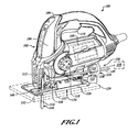
FIG. 1 is a perspective view of an example of a jigsaw having an angle indicator wheel visible through a window in the housing and a dust extraction airflow from a cutting area, through the housing and out of a vacuum port in accordance with the present teachings. -
FIG. 2 is a perspective view of another example of a jigsaw having an angle indicator wheel visible through a window in the housing and a dust extraction airflow from a cutting area, through a shoe member and out of a vacuum port that extends from the shoe member in accordance with the present teachings. -
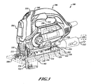
FIG. 3 is a perspective view of a further example of a jigsaw similar to the jigsaw ofFIG. 2 and includes a laser light module connected to a front of the housing and a keel assembly connected to a bottom of the housing in accordance with the present teachings. -
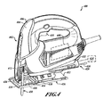
FIG. 4 is a perspective view of yet another example of a jigsaw having a shoe member that can be secured at a zero degree cutting angle (i.e., a perpendicular cutting angle) by moving the shoe member in an axial direction relative to the housing in accordance with the present teachings. -
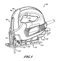
FIG. 5 is a perspective view of a further example of a jigsaw having a shoe member that can be secured at the zero degree cutting angle in accordance with the present teachings. -
FIG. 6 is a partial front view of the jigsaw ofFIG. 3 showing the cutting angle at one position selected from a range of positions in accordance with the present teachings. -
FIG. 7 is a partial side view of the jigsaw housing ofFIG. 1 showing the window through which a portion of the angle indicator wheel can be seen to indicate the angle between the jigsaw housing and the shoe member in accordance with the present teachings. -
FIG. 8 is similar toFIG. 7 and shows a perimeter of the window illuminating the information on the angle indicator wheel in accordance with the present teachings. -
FIG. 9 is similar toFIG. 7 and shows a portion of the angle indicator wheel illuminated and shining through the window in accordance with the present teachings. -
FIG. 10 is a simplified partial cross-sectional view of a housing of a jigsaw showing a dust extraction airflow from a cutting area up into an airflow pathway formed through the housing, through an inner periphery of the angle indicator wheel and exhausting through an exhaust port in a rear portion of the housing in accordance with the present teachings. -
FIG. 11 is similar toFIG. 10 and shows a dust extraction airflow from the cutting area through a scoop member that leads into an airflow pathway formed through the housing, through an inner periphery of the angle indicator wheel and exhausting through the exhaust port in the rear portion of the housing in accordance with the present teachings. -
FIG. 12 is a partial perspective view of a scoop member formed on a jigsaw housing through which a dust extraction airflow departs from the cutting area into a pathway formed in the housing in accordance with the present teachings. -
FIG. 13 is an exploded assembly view of an exemplary shoe subassembly that can be implemented with the jigsaws illustrated inFIGS. 1 ,2 and/or 3 in accordance with the present teachings. -
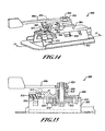
FIG. 14 is a perspective view of the shoe subassembly ofFIG. 13 showing a locking mechanism having a bevel lock arm and a shoe insert coupled to a channel formed in the shoe member in accordance with the present teachings. -
FIG. 15 is a simplified cross-sectional view of the shoe subassembly illustrated inFIG. 14 in accordance with the present teachings. -
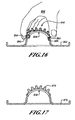
FIG. 16 is a diagram of a partial cross-sectional view of the shoe insert and the shoe member with a user flexing the shoe insert into a channel formed in the shoe member in accordance with the present teachings. -
FIG. 17 is similar toFIG. 16 and shows the shoe insert and the shoe member being a monolithic member in accordance with the present teachings. -
FIG. 18 is a flowchart of an exemplary method of assembling a shoe insert into a shoe member in accordance with the present teachings. -
FIG. 19 is a partial bottom view of a shoe member pivotally coupled to the housing having stop members that include a wedge shape in accordance with the present teachings. -
FIG. 20 is similar toFIG. 19 and shows the shoe assembly positioned at an angle other than the zero degree cutting angle (i.e., not at a perpendicular cutting angle) so that the stop members are not contained within complementary pockets formed in the channels of the shoe member in accordance with the present teachings. -
FIG. 21 is similar toFIG. 20 and shows the shoe assembly positioned at an angle other than the zero degree cutting angle so that the stop members are not contained within the complementary pockets formed in the channels of the shoe member. But in this example, the shoe member is engaged to the stop members in an axial direction opposite that ofFIG. 20 in accordance with the present teachings. - It should be understood that throughout the drawings, corresponding reference numerals can indicate like or corresponding parts and features. Moreover, certain terminology can be used for the purpose of reference only and do not limit the present teachings. For example, terms such as "upper," "lower," "above" and "below" can refer to directions in the drawings to which reference is made. Terms such as "front," "back," "rear" and "side" can describe the orientation of portions of the component, function, system, etc. within a consistent but arbitrary frame of reference which can be made more clear by reference to the text and the associated drawings describing the component, function, system, etc. under discussion. Such terminology may include the words specifically mentioned above, derivatives thereof and words of similar import. Similarly, the terms "first," "second" and other such numerical terms referring to structures, systems and/or methods do not imply a sequence or order unless clearly indicated by the context.
- With reference to
FIG. 1 , ajigsaw 100 generally includes ahousing 102 that can be formed of twohalf shells housing 102 can contain amotor 108. When activated by atrigger assembly 110, themotor 108 can provide a reciprocating and/or pendulum motion to acutting blade holder 112 on an end of a reciprocating shaft to drive acutting blade 114 at a cutting angle 116 (FIG. 6 ). Acontrol member 118 on a side of thehousing 102 can control a rate of reciprocation and/or a magnitude of a pendulum motion of thecutting blade 114. - A
shoe member 120 can be coupled to abottom 122 of thehousing 102 in such a way as to permit theshoe member 120 to pivot relative to thehousing 102. As theshoe member 120 pivots relative to thehousing 102, thecutting blade 114 can be orientated at various angles (i.e., one or more of the cutting angles 116 (FIG. 6 )) relative to theshoe member 120. - A
bottom surface 124 of theshoe member 120 can abut aworkpiece 126, which can be wood, plastic, metal, other suitable materials and one or more combinations thereof and can be in the form of pipe, sheet material, stock material, other suitable forms and/or materials and one or more combinations thereof. Theshoe member 120 can be pivoted relative to thehousing 102 to adjust the cutting angle 116 (FIG. 6 ) of thejigsaw 100, e.g., at a forty five degree cutting angle. As theshoe member 120 is moved relative to thehousing 102, anangle indicator wheel 128 that can be rotatably coupled to the shoe member 120 (see, e.g.,FIG. 9 ) can indicate thecutting angle 116 of thejigsaw 100. - Further, a
locking mechanism 130 can include abevel lever 132 that can be adjusted between an unlocked condition, as shown (in phantom) inFIG. 1 and a locked condition, as shown inFIG. 1 . In the unlocked condition, thelocking mechanism 130 can permit theshoe member 120 to pivot relative to thehousing 102. In the locked condition, thelocking mechanism 130 can prevent theshoe member 120 from pivoting relative to thehousing 102. In this regard, the cutting angle 116 (FIG. 6 ) to which theshoe member 120 can be pivoted relative to thehousing 102, when thelocking mechanism 130 is in the unlocked condition, can be indicated by theangle indicator wheel 128. - A
dust extraction port 134 can be formed on arear portion 136 of thehousing 102 such that avacuum source 138 can be connected with various suitable connections to thedust extraction port 134. Adust extraction airflow 140 can be extracted from acutting area 142. From thecutting area 142, thedust extraction airflow 140 can move into thehousing 102 near arear edge 144 of thecutting blade 114, through thehousing 102 and out through thedust extraction port 134. - The
dust extraction airflow 140 can travel through thehousing 102 and can be routed through an inner periphery of theangle indicator wheel 128. In one example, theangle indicator wheel 128 can be similar to anangle indicator wheel 708 having aninner periphery 720, as shown inFIG. 10 . In another example, theangle indicator wheel 128 can be similar to anangle indicator wheel 758 having aninner periphery 772, as shown inFIG. 11 . - In a further example and with reference to
FIGS. 1 and12 , thedust extraction airflow 140 can exit thecutting area 142 through ascoop member 148 that extends from thehousing 102. Thescoop member 148 can be similar to ascoop member 762, as shown inFIG. 11 . In the above examples, theshoe member 120 can be pivoted relative to thehousing 102 without interrupting thedust extraction airflow 140 through thehousing 102 and through theangle indicator wheel 128. - With reference to
FIG. 2 , ajigsaw 200 includes ahousing 202 that can be formed of twohalf shells housing 202 can contain amotor 208. When activated by atrigger assembly 210, themotor 208 can provide a reciprocating and/or pendulum motion to the reciprocating shaft to drive acutting blade 214 at one or more of the cutting angles 116 (FIG. 6 ). Acontrol member 216 on a side of thehousing 202 can control the rate of reciprocation and/or the magnitude of the pendulum motion of thecutting blade 214. - A
shoe member 218 can be coupled to abottom 220 of thehousing 202 in such a way as to permit theshoe member 218 to pivot relative to thehousing 202. As theshoe member 218 pivots relative to thehousing 202, thecutting blade 214 can be orientated at the various cutting angles 116 (FIG. 6 ) relative to theshoe member 218. Abottom surface 222 of theshoe member 218 can abut the workpiece 126 (FIG. 1 ). - As the
shoe member 218 is moved relative to thehousing 202, anangle indicator wheel 224 can be rotatably coupled to the shoe member 218 (see, e.g.,FIG. 9 ), and can indicate the cutting angle 116 (FIG. 6 ) of thejigsaw 200. Further, alocking mechanism 226 can include abevel lever 228 that can be adjusted between an unlocked condition (e.g., in phantom inFIG. 1 ) and a locked condition. The cutting angle 116 (FIG. 6 ) to which theshoe member 218 can be pivoted relative to thehousing 202, when thelocking mechanism 226 is in the unlocked condition, can be indicated by theangle indicator wheel 224. - A
dust extraction port 230 can be formed on arear portion 232 of theshoe member 218, in contrast to thedust extraction airflow 140 through the housing 102 (FIG. 1 ). Avacuum source 234 can be connected to thedust extraction port 230. Adust extraction airflow 236 can be extracted from acutting area 238. From thecutting area 238, thedust extraction airflow 236 can move through theshoe member 218 and out through thedust extraction port 230 that extends therefrom. Avacuum source adapter 240 can be connected to thedust extraction port 230 formed in theshoe member 218 and can be used to connect to thevacuum source 234.Inlets 242 can be formed at one or more locations on theshoe member 218 adjacent thecutting area 238. From theinlets 242, thedust extraction airflow 236 can be routed through channels in theshoe member 218 to thedust extraction port 230. - With reference to
FIG. 3 , ajigsaw 300 can be similar to the exemplary jigsaw 200 (FIG. 2 ) and can also include akeel assembly 302 and/or alaser module 304 that can be connected to a housing 306 having twohousing half shells jigsaw 200. Thejigsaw 300 can further include adust extraction airflow 312 through ashoe member 314. Thedust extraction airflow 312 can exit from adust extraction port 316 that can extend therefrom. Thelaser module 304 can project alaser light 318 and can produce alaser light pattern 320. Thelaser light pattern 320 can produce, for example, a sequence of dashes and/or dots beyond afront side 322 of thecutting blade 114 and can highlight a path of thecutting blade 114 through theworkpiece 126. - The
keel assembly 302 can provide additional straight-line accuracy when cutting a straight line in the workpiece 126 (e.g., can help avoid wandering of the jigsaw cutting line). Thekeel assembly 302 can be pivoted with the housing 306 when theshoe member 314 is moved at an angle (i.e., one or more cutting angles 116 (FIG. 6 )) relative to the housing 306. In this regard, theshoe member 314 can be pivoted relative to the housing 306 but thekeel assembly 302 can remain generally in line with the housing 306 so as to provide, for example, a straight bevel cut through theworkpiece 126. - With reference to
FIG. 4 , ajigsaw 400 includes ahousing 402 that can be formed of twohalf shells housing 402 can contain amotor 408. When activated by atrigger assembly 410, themotor 408 can provide a reciprocating and/or pendulum motion to the reciprocating shaft to drive thecutting blade 114 at one of the cutting angles 116 (FIG. 6 ). - A
shoe member 412 can be coupled to abottom 414 of thehousing 402 in such a way as to permit theshoe member 412 to pivot relative to thehousing 402. As theshoe member 412 pivots relative to thehousing 402, thecutting blade 114, can be orientated at various angles (i.e., one or more of the cutting angles 116 (FIG. 6 )) relative to theshoe member 412. As is known in the art, abottom surface 416 of theshoe member 412 can abut the workpiece 126 (FIG. 1 ). - A
locking mechanism 418 can be adjusted between an unlocked condition that can permit theshoe member 412 to pivot relative to thehousing 402 and a locked condition that can prevent theshoe member 412 from pivoting relative to thehousing 402. In one example, thelocking mechanism 418 can include one or more fasteners (not shown) that can secure theshoe member 412 to thebottom 414 of thehousing 402. The fasteners can be partially removed to permit theshoe member 412 to pivot relative to thehousing 402. - A dust extraction port 420 can be formed on a
rear portion 422 of thehousing 402 such that avacuum source 424 can be connected to the dust extraction port 420. Adust extraction airflow 426 can be extracted from a cutting area 428. From the cutting area 428, thedust extraction airflow 426 can move into thehousing 402 near arear side 430 of a cutting blade 438, through thehousing 402 and out through the dust extraction port 420. - With reference to
FIG. 5 , a jigsaw 500 generally includes ahousing 502 that can be formed of twohalf shells housing 502 can contain amotor 508. When activated by atrigger assembly 510, themotor 508 can provide a reciprocating and/or pendulum motion to the reciprocating shaft to drive acutting blade 114 at one or more of the cutting angles 116 (FIG. 6 ). - A
shoe member 514 can be coupled to abottom 516 of thehousing 502 in such a way as to permit theshoe member 514 to pivot relative to thehousing 502 in a fashion that is similar to the jigsaw 400 (FIG. 4 ). Abottom surface 518 of theshoe member 514 can abut the workpiece 126 (FIG. 1 ). In addition, alocking mechanism 520 can be adjusted between an unlocked condition that can permit theshoe member 514 to pivot relative to thehousing 502 and a locked condition that can prevent theshoe member 514 from pivoting relative to thehousing 502. Thelocking mechanism 520 can include one or more fasteners (not shown) that can secure theshoe member 514 to thebottom 516 of thehousing 502. The fasteners can be partially removed (i.e., the unlocked condition) to permit theshoe member 514 to pivot relative to thehousing 502. - A
storage container 530 can be formed on arear portion 532 of thehousing 502 such that blades, tools, etc. can be stored within thestorage container 530. Astorage container cover 534, illustrated in an open condition, can be closed (shown in phantom line) to contain whatever may be placed within thestorage container 530. With reference toFIG. 6 , the cuttingangle 116 of thecutting blade 114 of thejigsaw 300 is shown relative to theshoe member 314 of thejigsaw 300. Thekeel assembly 302 is also attached to the housing 306. The cutting angle 116 (illustrated in solid line) is positioned at the zero degree cutting angle, i.e., a perpendicular cutting angle relative to theshoe member 314. The cuttingangle 116 can also be positioned at one or more cutting angles such as a cutting angle 352 (shown in phantom line) that can be positioned at about positive fifteen degrees, while a cutting angle 354 (shown in phantom line) can be positioned at about negative thirty degrees. A cutting angle 356 (shown in phantom line) can be positioned at about positive forty five degrees. It will be appreciated in light of the disclosure that various cutting angles can be implemented with any of thejigsaws FIGS. 1-5 ). - With reference to
FIGS. 1 - 5 , it will be appreciated in light of the disclosure that any of thejigsaws keel assembly 302 attached thereto. Moreover, theshoe member housing locking mechanism shoe member shoe member jigsaw shoe member FIGS. 19 and 20 , a shoe member 900 can be moved in adirection 914 that is axially backward relative to a cutting direction of the jigsaw. With reference toFIG. 21 , ashoe member 950 can be moved in a direction 964 that is axially forward or in line with a cutting direction of the jigsaw, as is discussed below. - With reference to
FIG. 7 , awindow 600 can be formed in ahousing 602 through which a portion of anangle indicator wheel 604 can be displayed.Numbers 606 can be affixed to theangle indicator wheel 604 such thatcertain numbers 606 can be displayed in thewindow 600 to indicate a specific angular position of theshoe member FIGS. 1 - 3 ) relative to the workpiece 126 (FIG. 1 ). It will be appreciated in light of the disclosure that thenumbers 606 are but one example of the information that can be displayed through thewindow 600. Other icons, graphics, symbols, specific indicia and/or one or more combinations thereof can be used and, as such, can be descriptive of angular increments between zero degrees and forty five degrees. For example, a line 608 (FIG. 8 ) can be aligned with thenumbers 606. - The
window 600 in thehousing 602 can further containarrows 610 and/or one or more other suitable additional indicators that can provide for a relatively more precise alignment of theangle indicator wheel 604 in thewindow 600 and thus at a desired cutting angle. In this regard, the user can more readily identify the exact position of theshoe member numbers 606 and/or other graphics, icons, etc. in thewindow 600 relative to thearrows 610 formed around thewindow 600. It will be appreciated in light of the disclosure that thewindow 600, as described above, can be implemented on any of thejigsaws 100, thejigsaw 200 and/or thejigsaw 300. - In one example and with reference to
FIG. 8 , awindow 620 can include aperimeter illumination mechanism 622 that can illuminatenumbers 624 on anangle indicator wheel 626 to more readily view thenumbers 624. Theperimeter illumination mechanism 622 that can emanate light 628 from the entireinner periphery 630 of thewindow 620 or portions thereof. Theperimeter illumination mechanism 622 can include one or more light emitting diodes of one or various colors, one or more small incandescent bulbs and/or one or more combinations thereof to provide suitable illumination to theangle indicator wheel 604. - With reference to
FIG. 9 , anangle indicator wheel 640 can contain within the angle indicator wheel 640 (or adjacent thereto), anillumination source 642 that can shine through theangle indicator wheel 640 and illuminatenumbers 644 thereon. By illuminating theangle indicator wheel 640, portions of theangle indicator wheel 640 can glow (i.e., emit light 646) as viewed through awindow 648. The glowingangle indicator wheel 640 can be shown to more readily highlight thenumbers 644 on theangle indicator wheel 640. It will be appreciated in light of the present disclosure that thewindow 600, thewindow 620 or thewindow 648 can be implemented on thejigsaw 100, thejigsaw 200 and thejigsaw 300. - With reference to
FIG. 10 , adust extraction airflow 700 can be directed through anairflow pathway 702 that can be established by an exemplary housing 704 of ajigsaw 706. In one example, a portion of theairflow pathway 702 can be through anangle indicator wheel 708, which can be similar to the angle indicator wheel 128 (FIG. 1 ). Thedust extraction airflow 700 can begin at arear edge 710 of thecutting blade 114. Thedust extraction airflow 700 can continue up into theairflow pathway 702 that can be provided bymultiple ribs 712 formed in the housing 704. - The
dust extraction airflow 700 can continue through theairflow pathway 702 that can continue through the housing 704, above ashoe block member 714 toward arear portion 716 of the housing 704. Thedust extraction airflow 700 can turn downward through theairflow pathway 702 toward ashoe member 718 and can be directed through aninner periphery 720 of theangle indicator wheel 708 so as to define a portion of theairflow pathway 702 therethrough. Thedust extraction airflow 700 can move through theangle indicator wheel 708 and out through a dust extraction port 722 formed in therear portion 716 of the housing 704. - A
vacuum source 724 can attach to the dust extraction port 722 formed in the housing 704 to establish thedust extraction airflow 700 through theairflow pathway 702 from therear edge 710 of thecutting blade 114 out through the dust extraction port 722. Similar to what is shown inFIG. 6 , theshoe member 718 can be moved relative to the housing 704 and can establish and maintain thedust extraction airflow 700 through theairflow pathway 702 in any of the cutting angles 116 (FIG. 6 ). - In one example, an
adapter member 726 can connect the dust extraction port 722 to thevacuum source 724. Theadapter member 726 can be configured as a component that can releaseably couple to the dust extraction port 722 and/or thevacuum source 724 or can be integral or fixedly coupled to the dust extraction port 722 and/or thevacuum source 724. - With reference to
FIG. 11 , adust extraction airflow 750 can be directed through anairflow pathway 752 formed in an exemplary housing 754 of ajigsaw 756. It will be appreciated in light of the disclosure that thedust extraction airflow 750 through theairflow pathway 752 can be implemented on the jigsaw 100 (FIG. 1 ). In this regard, a portion (or all) of thedust extraction airflow 750 can be directed through anangle indicator wheel 758, which can be similar to the angle indicator wheel 128 (FIG. 1 ). - In one example, the
dust extraction airflow 750 can begin at arear edge 760 of thecutting blade 114. Thedust extraction airflow 750 can continue up through anair scoop member 762 and intomultiple ribs 764 formed in the housing 754 that can establish theairflow pathway 752. Theairflow pathway 752 can continue through the housing 754, above ashoe block member 766 toward a rear portion 768 of the housing 754. Thedust extraction airflow 750 in theairflow pathway 752 can turn downward toward ashoe member 770 and can be directed through aninner periphery 772 of theangle indicator wheel 758. Theairflow pathway 752 can move through theangle indicator wheel 758 and out through adust extraction port 774 formed in the rear portion 768 of the housing 754. - A vacuum source 776 can attach to the
dust extraction port 774 formed in the housing 754 to establish thedust extraction airflow 750 from therear edge 760 of thecutting blade 114 out through thedust extraction port 774. Similar to what is shown inFIG. 6 , theshoe member 770 can be moved relative to the housing 754 that can establish theairflow pathway 752 in any of the cutting angles 116 (FIG. 6 ). It will be appreciated in light of the disclosure that thevacuum source adapter member 778 can connect thedust extraction port 774 to the vacuum source 776. Theadapter member 778 can be configured as a component that can releaseably couple to thedust extraction port 774 and/or the vacuum source 776 or can be integral or fixedly coupled to thedust extraction port 774 and/or the vacuum source 776. - With reference to
FIG. 12 , thescoop member 148 can be positioned behind anupper carrier assembly 150 that is configured to support thecutting blade 114. Behind thescoop member 148, theshoe member 120 can be secured to thebottom 122 of thehousing 102. Thescoop member 148 can establish afront lip 152 that can extend toward the cuttingarea 142. From thefront lip 152, two arcuateside wall members 154 can extend upward toward thehousing 102. - In one example, the arcuate
side wall members 154 and thefront lip 152 can be configured as a component that can releaseably couple to thehousing 102 or can be integral or fixedly coupled to thehousing 102. Thedust extraction airflow 140 can enter through thescoop member 148 and travel from thescoop member 148 through the housing 102 (e.g., through theairflow pathway 752 inFIG. 11 ) to be exhausted from the dust extraction port 134 (FIG. 1 ). - With reference to
FIGS. 13 ,14 and 15 , ashoe subassembly 800 includes ashoe member 802, ashoe block member 804 and abevel lever 806. Thebevel lever 806 can be attached to theshoe block member 804 with afastener 808 that can include a spring 810 to provide tension to thebevel lever 806, especially in the locked condition. In one example, the spring 810 can be omitted. - A
clamp member 812 can be connected to abottom surface 814 of theshoe member 802 with afastener 816. In another example, theclamp member 812 can be configured as a component that can releaseably couple to theshoe member 802 or can be integral or fixedly coupled to theshoe member 802. Ahead 818 of thefastener 808 can be received in anaperture 820 formed in theclamp member 812. A threadedend 822 of thefastener 808 can be received by a threadedmember 824 that can be fixed to thebevel lever 806. -
Posts 826 that each can extend from theshoe block member 804 can extend throughgrooves 828 formed on theshoe member 802 andgrooves 830 on theclamp member 812. Thefastener 808 can also pass through agroove 832 formed on theshoe member 802. Thegroove 828, thegroove 830 and/or thegroove 832 can be used to align theshoe member 802, theshoe block member 804 and theclamp member 812. The threadedmember 824 can be configured to be fixed coupled to or integral with thebevel lever 806. - Similar to the
bevel lever 132 inFIG. 1 , thebevel lever 806 can be moved between the locked condition and the unlocked condition. When moving from the unlocked condition to the locked condition, thebevel lever 806 moves the threadedmember 824 to draw thefastener 808 upward (i.e., toward the top of the page inFIG. 15 ). By drawing thefastener 808 upward, a clamping force between theclamp member 812 and theshoe block member 804 on theshoe member 802 can be increased. In the locked condition, the clamping force between theclamp member 812 and theshoe block member 804 is sufficient to prevent the pivoting of theshoe member 802. As thebevel lever 806 is moved from the unlocked condition to the locked condition, the movement of the threadedmember 824 with thebevel lever 806 can push thefastener 808 downward. By pushing thefastener 808 downward, the clamping force can be sufficiently reduced to a value such that theshoe member 802 can pivot relative to theshoe block member 804 and ultimately a housing of a jigsaw to which theshoe block member 804 can be attached, e.g., the jigsaw 100 (FIG 1 .). - With reference to
FIG. 14 , aninteraction member 850 can secure to and can extend from theshoe block member 804. Theinteraction member 850 can contact a first row ofpartial gear teeth 852 formed on ashoe insert 854 that can be coupled to theshoe member 802. The first row ofpartial gear teeth 852 can be adjacent a second row ofpartial gear teeth 856. Theshoe insert 854 can be formed of a flexible material so as to permit the bending of theshoe insert 854 into a curved channel 858 (FIG. 13 ) formed in theshoe member 802. - The first row of
partial gear teeth 852 can selectively contact theinteraction member 850 that extends from theshoe block member 804. The second row ofpartial gear teeth 856 can mesh with partial gear teeth 860 formed on an angle indicator wheel 862 (FIG. 13 ). In one example, one or more intermediate gears (whole or partial) can be disposed between a shoe member and an indicator wheel so that pivoting the shoe member relative to a jigsaw housing can rotate the one or more intermediate gears and the indicator wheel. - The
interaction member 850 that extends from theshoe block member 804 can provide a momentary positive lock between theshoe block member 804 and theshoe member 802 via engagement between theinteraction member 850 and the first row ofpartial gear teeth 852. As theshoe member 802 is pivoted relative to theshoe block member 804, theinteraction member 850 can deflect and jump from each of thepockets 864 formed betweengear teeth 866 in the first row ofpartial gear teeth 852. - In one example, the
interaction member 850 can be aleaf spring 868 that can connect to theshoe block member 804. The deflection of theleaf spring 868, as a portion of theleaf spring 868 jumps between thepockets 864 formed between thegear teeth 866, can provide an audible click. The audible click can be an indicator to a user that theshoe member 802 has pivoted to the next angular detent, e.g., a move from the fifteen degree cutting angle 352 (FIG. 6 ) to a thirty degree cutting angle. In a further example, a spring biased member, such as a ball, post, etc., can similarly interact with thepocket 864 of thegear teeth 866. The spring biased member can be coupled to theshoe block member 804 and extend toward theshoe insert 854. - The
shoe subassembly 800 can be assembled, as illustrated inFIG. 14 , prior to fully assembling the jigsaw, which, for example, can be thejigsaw FIGS. 1 ,2 and3 ). In addition, a locking mechanism 870 (FIG. 14 ) can be configured so that the shoe clamping force for thelocking mechanism FIGS. 1 ,2 and15 ) can be set and configured prior to assembling theshoe subassembly 800 with thejigsaw housings locking mechanism FIGS. 1 ,2 and15 ) between the locked and unlocked conditions. The range of clamping force values can be set, thus predetermined, by selecting a distance 872 from thehead 818 of thefastener 808 and the threadedmember 824 on thebevel lever 806. It will be appreciated in light of the disclosure that theshoe subassembly 800 can be assembled, the clamping force can be set and theshoe subassembly 800 can be shipped from a location other than in a location where the jigsaw is assembled. - With reference to
FIG. 16 , theshoe insert 854 having the two rows ofpartial gear teeth 852, 818 (FIG. 14 ) can be assembled into theshoe member 802, which can be separately manufactured from theshoe insert 854. Theshoe insert 854, as a separate component, can include the relatively complex structure detailed geometry of the first and second partial rows ofgear teeth shoe member 802. - With reference to
FIG. 17 , ashoe insert 874 having the two rows ofpartial gear teeth 852, 856 (FIG. 14 ) can be produced with ashoe member 876 that can be monolithically manufactured together with theshoe insert 874. In one example, theshoe insert 874 and theshoe member 876 are all one piece of metal. While in another example, theshoe insert 854 can be manufactured separately but can be cast in place or mechanically or chemically fastened to theshoe member 876. In the above examples, theshoe insert 874 need not be flexible. - With reference to
FIG. 18 , a flowchart method of inserting the shoe insert 854 (FIG. 16 ) into the shoe member 802 (FIG. 16 ) generally includes, at 880, providing ashoe member 802 that defines a curved channel 858 (FIG. 13 ) and providing ashoe insert 854 configured to be accepted by thecurved channel 858. At 882, a first end 884 (FIG. 16 ) of theshoe insert 854 can abut a first end 886 (FIG. 16 ) of thecurved channel 858. At 888, at least a portion of theshoe insert 854 can be bent, flexed or otherwise distorted by a user 890 (FIG. 16 ). At 892, a second end 894 (FIG. 16 ) of theshoe insert 854 can be aligned with a second end 896 (FIG. 16 ) of thecurve channel 858. At 898, theshoe insert 854 can be released from the bending or flexing at 888. After 898, the method can end. - With reference to
FIGS. 19 and 20 , an exemplary shoe member 900 is shown with portions of a housing 902 (and in some examples a shoe block member 904) visible through the shoe member 900. As such, abottom 906 of thehousing 902 can define stopmembers 908 that can interact with acomplementary pocket 910 formed inchannels 912 in the shoe member 900. In an example where theshoe block member 904 is implemented, theshoe block member 904 can connect to thehousing 902 and thestop members 908 can extend from theshoe block member 904. - In one example, one or more of the
stop members 908 can have a wedge shape and thepockets 910 can have a complementary wedge shape. In a further example, thestop members 908 can have a circular shape and thepockets 910 can have a complementary circular shape. When the shoe member 900 is positioned at a zero degree angular position (i.e., a perpendicular cutting angle), the shoe member 900 can be advanced in adirection 914 that can be axially backward relative to a cutting direction 916 (i.e., toward the right side of the page inFIG. 19 ) to engage thestop members 908 that extend from thehousing 902. In this regard, thestop members 908 can move intocomplimentary pockets 910 and can provide a positive engagement at zero degrees. - Because of the wedge shape of the
stop members 908, thecomplementary pockets 910 can be axially advanced onto the wedge shapedstop members 908. When there is any slack (i.e., gaps) in the contact between thestop members 908 and thecomplementary pockets 910, additionally advancing the shoe member 900 so that thecomplementary pockets 910 receive more and more of the wedge shapedstop members 908, can further close any gaps relative to a configuration of stop members not having the wedge shape but having parallel sides. In contrast, thestop members 908 having the wedge shape, can define walls 918 (FIG. 20 ) that converge toward the cuttingdirection 916 of the jigsaw, i.e., toward the left inFIG. 1 . - By taking up the other tolerances in the shoe subassembly 800 (
FIG. 14 ), other tolerances in theshoe subassembly 800 do not need to be held as tight as would otherwise be without the wedge shapedstop members 908 that extend from thehousing 902 orshoe block member 804. It will be appreciated in light of the disclosure that the shoe member 900 and the above describedshoe sub-assembly 800 can be implemented on any of thejigsaws - With reference to
FIG. 20 , the shoe member 900 is shown in a position other than zero degrees (e.g., the cutting angle 354 (FIG. 6 )). In this instance, the wedge shapedstop members 908 cannot be received within the wedge shapedpockets 910 formed in the shoe member 900 but advance along thechannels 904 that containpockets 910 as the shoe member pivots relative thehousing 902. It will be appreciated in light of the disclosure that stopmembers 908 can extend from the housing 902 (or the shoe block member 904) at other angular positions (i.e., not at zero degrees) so that the shoe member 900 can be axially moved relative tohousing 902 to provide positive engagement at one or more cutting angles. For example, stop members can provide for positive engagement of the shoe member 900 at zero degrees and at forty-five degrees. In other examples, stop members can provide for positive engagement of the shoe member 900 at only forty-five degrees. - With reference to
FIG. 21 , anotherexample shoe member 950 is shown with portions of a housing 952 (or a shoe block member 954) visible through theshoe member 950. As such, a bottom of thehousing 952 can define stopmembers 956 that can interact withcomplimentary pockets 958 formed inchannels 960 in theshoe member 950. The shape of thestop members 956 and/or thepockets 958 can be similar to thestop members 908 andcomplimentary pockets 910 illustrated inFIGS. 19 and 20 . Theshoe member 950, however, can be positioned at a zero degree angular position and can be advanced in adirection 960 that can be axially forward relative to (i.e., in line with) thecutting direction 914 to engage thestop members 956 that extend from thehousing 952. In this regard, the motion of theshoe member 950 can be similar to that of theshoe member 902 andFIG. 19 , but can be moved indirection 960, in contrast to direction 912 (FIG. 19 ). - While specific aspects have been described in the specification and illustrated in the drawings, it will be understood by those skilled in the art that various changes can be made and equivalents can be substituted for elements and components thereof without departing from the scope of the present teachings, as defined in the claims. Furthermore, the mixing and matching of features, elements, components and/or functions between various aspects of the present teachings are expressly contemplated herein so that one skilled in the art will appreciate from the present teachings that features, elements, components and/or functions of one aspect of the present teachings can be incorporated into another aspect, as appropriate, unless described otherwise above. Moreover, many modifications may be made to adapt a particular situation, configuration or material to the present teachings without departing from the essential scope thereof.
Claims (15)
- A jigsaw comprising:a housing containing a motor activated by a trigger assembly, said housing defining a window;a shoe member pivotally connected to said housing; andan indicator wheel disposed in said housing so that a portion of said indicator wheel is visible through said window, wherein pivoting of said shoe member relative to said housing causes said indicator wheel to rotate.
- The jigsaw of Claim 1, wherein said shoe member defines an angle relative to said housing and said portion of said indicator wheel visible through said window is descriptive of said angle.
- The jigsaw of Claim 1 or Claim 2, further comprising gear teeth that extend from said shoe member and mesh with gear teeth that extend from said indicator wheel.
- The jigsaw of any preceding claim, wherein said indicator wheel includes information descriptive of angular increments between about zero degrees and about forty five degrees, said information visible through said window.
- The jigsaw of any preceding claim, wherein said housing defines an airflow pathway through which a dust extraction airflow passes capable of clearing debris from a cutting area.
- The jigsaw of Claim 5, wherein said airflow pathway is disposed through an inner periphery of said indicator wheel.
- The jigsaw of Claim 6, wherein said angle indicator wheel is coupled for rotation on a portion of said housing through which said airflow pathway passes.
- The jigsaw of any one of claims 5 to 7, wherein said airflow pathway is through said shoe member.
- The jigsaw of any one of claims 5 to 8, further comprising a scoop member that extends from said housing and toward said cutting area, wherein said scoop member defines a portion of said airflow pathway through which said dust extraction airflow passes from said cutting area and through said housing.
- The jigsaw of any preceding claim, wherein said shoe member produces an audible click as said shoe member moves through each angular increment in a range of angular increments relative to said housing.
- The jigsaw of any preceding claim, further comprising an illumination mechanism that illuminates said portion of said indicator wheel visible through said window.
- The jigsaw of any preceding claim, further comprising a locking mechanism having an unlocked condition that permits said shoe member to pivot relative to said housing and a locked condition that prevents said shoe member from pivoting relative to said housing.
- The jigsaw of any preceding claim, further comprising a stop member that extends from said housing, wherein said shoe member is configured to be moved axially relative to said housing so that a portion of said shoe member engages said stop member to prevent said shoe member from pivoting relative to said housing.
- A method of selecting a cutting angle for a jigsaw, the method comprising:permitting a shoe member to pivot about a housing of the jigsaw;rotating an angle indicator in said housing, when said shoe member pivots about said housing; anddisplaying a portion of said indicator wheel in a window in said housing, wherein said portion of said indicator wheel, visible through said window, is descriptive of an angle between said housing and said shoe member.
- The method of Claim 14, further comprising establishing a dust extraction airflow through an airflow pathway, wherein a portion of said airflow pathway is through an inner periphery of said indicator wheel and/or or through said shoe member.
Applications Claiming Priority (1)
| Application Number | Priority Date | Filing Date | Title |
|---|---|---|---|
| US11/859,139 US9981327B2 (en) | 2007-09-21 | 2007-09-21 | Cutting angle indicator in jigsaw housing with dust extraction |
Publications (3)
| Publication Number | Publication Date |
|---|---|
| EP2039454A2 true EP2039454A2 (en) | 2009-03-25 |
| EP2039454A3 EP2039454A3 (en) | 2011-04-13 |
| EP2039454B1 EP2039454B1 (en) | 2014-11-12 |
Family
ID=40120445
Family Applications (1)
| Application Number | Title | Priority Date | Filing Date |
|---|---|---|---|
| EP08164643.2A Ceased EP2039454B1 (en) | 2007-09-21 | 2008-09-18 | Cutting angle indicator in jigsaw housing |
Country Status (4)
| Country | Link |
|---|---|
| US (2) | US9981327B2 (en) |
| EP (1) | EP2039454B1 (en) |
| CN (1) | CN201316838Y (en) |
| AU (1) | AU2008221574A1 (en) |
Cited By (5)
| Publication number | Priority date | Publication date | Assignee | Title |
|---|---|---|---|---|
| GB2466382A (en) * | 2008-12-22 | 2010-06-23 | Bosch Gmbh Robert | Compass saw with lever for adjusting device |
| WO2011026680A1 (en) * | 2009-09-02 | 2011-03-10 | Robert Bosch Gmbh | Tool device |
| WO2011072922A1 (en) * | 2009-12-17 | 2011-06-23 | Robert Bosch Gmbh | Hand-held machine tool |
| EP2556910A1 (en) * | 2011-08-12 | 2013-02-13 | Metabowerke GmbH | Electric manual tool device with a footplate that can be adjusted to various angled positions |
| US8578615B2 (en) * | 2011-09-12 | 2013-11-12 | Black & Decker Inc. | Jigsaw with deployable keel and tiltable shoe |
Families Citing this family (24)
| Publication number | Priority date | Publication date | Assignee | Title |
|---|---|---|---|---|
| US7958641B1 (en) * | 2007-05-09 | 2011-06-14 | Woodman Tools, Llc | Rolling plate assembly attachment for portable power cutting tools including an improved structural design and manufactured out of improved materials, an improved wheel configuration, and an adjustable bevel gear and a cutting guide |
| US8317350B2 (en) | 2009-02-25 | 2012-11-27 | Black & Decker Inc. | Power tool with a light for illuminating a workpiece |
| US20110058356A1 (en) | 2009-02-25 | 2011-03-10 | Black & Decker Inc. | Power tool with light emitting assembly |
| US8328381B2 (en) | 2009-02-25 | 2012-12-11 | Black & Decker Inc. | Light for a power tool and method of illuminating a workpiece |
| JP5620709B2 (en) * | 2010-04-28 | 2014-11-05 | 株式会社マキタ | Cutting tool |
| CN102275155A (en) * | 2010-06-12 | 2011-12-14 | 株式会社牧田 | Motor-driven electric tool |
| US12059780B2 (en) | 2010-09-30 | 2024-08-13 | Black & Decker Inc. | Lighted power tool |
| US9328915B2 (en) | 2010-09-30 | 2016-05-03 | Black & Decker Inc. | Lighted power tool |
| US9028088B2 (en) | 2010-09-30 | 2015-05-12 | Black & Decker Inc. | Lighted power tool |
| WO2012121943A2 (en) * | 2011-03-08 | 2012-09-13 | Infusion Brands, Inc. | Dual bladed jig saw |
| EP2694260B1 (en) | 2011-04-01 | 2017-01-18 | Milwaukee Electric Tool Corporation | Jigsaw |
| US9132568B2 (en) * | 2011-10-11 | 2015-09-15 | Echo, Inc. | Chainsaw with cutting chain tensioner |
| US9242355B2 (en) | 2012-04-17 | 2016-01-26 | Black & Decker Inc. | Illuminated power tool |
| JP2014004666A (en) | 2012-06-26 | 2014-01-16 | Makita Corp | Jigsaw |
| DE102013208132A1 (en) * | 2013-05-03 | 2014-11-06 | Robert Bosch Gmbh | Hand tool |
| JP5995785B2 (en) * | 2013-05-31 | 2016-09-21 | 株式会社マキタ | Brush cutter |
| CN105592991A (en) * | 2013-10-01 | 2016-05-18 | 日立工机株式会社 | Cutting tool |
| US9559628B2 (en) | 2013-10-25 | 2017-01-31 | Black & Decker Inc. | Handheld power tool with compact AC switch |
| US9643290B1 (en) * | 2014-06-25 | 2017-05-09 | Andrew Leighner | Line following power tool |
| US10850380B2 (en) * | 2015-06-02 | 2020-12-01 | Milwaukee Electric Tool Corporation | Multi-speed power tool with electronic clutch |
| US11110584B2 (en) * | 2016-11-17 | 2021-09-07 | Black & Decker Inc. | Jigsaw blade storage |
| DE102018102855A1 (en) * | 2017-08-11 | 2019-02-14 | Festool Gmbh | Hand machine tool with a suction connection |
| JP7135170B2 (en) * | 2019-06-27 | 2022-09-12 | 株式会社マキタ | board cutter |
| CN218745244U (en) * | 2022-09-29 | 2023-03-28 | 米沃奇电动工具公司 | wire saw |
Citations (1)
| Publication number | Priority date | Publication date | Assignee | Title |
|---|---|---|---|---|
| US3131736A (en) | 1961-04-10 | 1964-05-05 | Milwaukee Electric Tool Corp | Portable motor driven jig saw |
Family Cites Families (259)
| Publication number | Priority date | Publication date | Assignee | Title |
|---|---|---|---|---|
| US1102018A (en) | 1912-06-06 | 1914-06-30 | Kerner Mfg Company | Power-driven handsaw. |
| GB221671A (en) | 1923-10-22 | 1924-09-18 | George Scattergood | Improvements in or relating to guards for circular saws |
| US2010882A (en) * | 1934-10-18 | 1935-08-13 | Walker Turner Company Inc | Self-indexing miter gauge |
| DE716266C (en) | 1937-06-01 | 1942-01-15 | Hans Ehlermann Dipl Ing | Device for dissipating the heat from the rotor core of electric hand tools |
| US2377673A (en) | 1944-08-21 | 1945-06-05 | Clarence F Chaddock | Blade guide for motor-driven circular handsaws |
| US2543486A (en) * | 1945-06-08 | 1951-02-27 | Excel Auto Radiator Company | Portable power saw |
| US2623557A (en) | 1951-06-05 | 1952-12-30 | John T Kendall | Portable power-driven recessing apparatus |
| US2749951A (en) | 1952-04-17 | 1956-06-12 | Tetzner Gustav | Band saw blade guide |
| US2775272A (en) | 1953-11-27 | 1956-12-25 | Walter A Papworth | Portable power driven reciprocable cutting tool |
| US2819742A (en) | 1955-07-05 | 1958-01-14 | Oster John Mfg Co | Kerf guide and splitter |
| DE1760076U (en) | 1957-11-26 | 1958-01-16 | Metabowerk Closs Rauch & Schni | PROTECTIVELY INSULATED ELECTRICAL TOOLS, IN PARTICULAR JIGSAW. |
| US2934106A (en) | 1958-01-09 | 1960-04-26 | Continental Machines | Saw band guide |
| DE1795934U (en) | 1958-02-11 | 1959-09-17 | Scintilla Ag | ADDITIONAL DEVICE FOR A MOTOR-DRIVEN HAND SAW. |
| US2916062A (en) | 1958-09-18 | 1959-12-08 | Dormeyer Corp | Splitter for portable electric saw |
| US3093773A (en) | 1959-03-23 | 1963-06-11 | Fed Pacific Electric Co | Panelboard with circuit protective devices |
| US3087519A (en) | 1960-11-25 | 1963-04-30 | Black & Decker Mfg Co | Pivoting shoe for portable electric jig saw |
| US3146809A (en) | 1961-04-06 | 1964-09-01 | Skil Corp | Adjustable guide plate for jig saws |
| US3109465A (en) | 1961-05-19 | 1963-11-05 | Sure Hit Products Inc | Saw guide assemblies |
| US3116768A (en) | 1962-05-07 | 1964-01-07 | Lasar William | Band saw guide |
| DE1279923B (en) | 1965-01-21 | 1968-10-10 | Scintilla Ag | Device for generating an additional feed movement for the saw blade of a jigsaw machine |
| US3353573A (en) | 1965-05-19 | 1967-11-21 | Mc Graw Edison Co | Portable power tool |
| DE1278728B (en) | 1966-03-25 | 1968-09-26 | Ackermann U Schmitt K G | Guide device on a motor-driven jigsaw |
| US3388728A (en) | 1966-04-15 | 1968-06-18 | Martin Marietta Corp | Portable power tools |
| US3457796A (en) | 1966-06-23 | 1969-07-29 | Rockwell Mfg Co | Tool |
| CH474341A (en) | 1966-08-18 | 1969-06-30 | Perles Elektrowerkzeuge Und Mo | Jigsaw |
| US3461732A (en) | 1966-12-19 | 1969-08-19 | Rockwell Mfg Co | Portable power driven reciprocating saw |
| US3478786A (en) | 1967-02-03 | 1969-11-18 | Otto Hendrickson | Adjustably controlled saber saw |
| US3542097A (en) | 1968-05-02 | 1970-11-24 | Singer Co | Chuck assembly for sabre saws |
| US3834019A (en) | 1972-11-22 | 1974-09-10 | Maremont Corp | Apparatus for cutting exhaust system tubes |
| US3805383A (en) | 1972-11-22 | 1974-04-23 | Maremont Corp | Exhaust system tube cutting apparatus with improved cutting efficiency |
| SE395606B (en) | 1973-12-04 | 1977-08-22 | Persson Curt | SAWING DEVICE FOR CUTTING UP A PLASTER or other similarly shaped body |
| DE2435845C2 (en) | 1974-07-25 | 1984-09-20 | Metabowerke KG Closs, Rauch & Schnizler, 7440 Nürtingen | Motor-driven jigsaw with tiltable table |
| US3938251A (en) | 1975-03-10 | 1976-02-17 | The Raymond Lee Organization, Inc. | Saber or jig saw with demountable foot plate and shield |
| US3969796A (en) | 1975-09-17 | 1976-07-20 | General Electric Company | Releasable fastening arrangement for a radio housing and a battery housing |
| DE2546527C2 (en) | 1975-10-17 | 1993-05-27 | Robert Bosch Gmbh, 7000 Stuttgart | Jigsaw |
| DE2650470C2 (en) | 1976-11-04 | 1984-03-22 | Eugen Lutz GmbH u. Co Maschinenfabrik, 7130 Mühlacker | Jigsaw |
| DE2655583C2 (en) | 1976-12-08 | 1982-07-01 | Black & Decker, Inc., 19711 Newark, Del. | Jigsaw |
| US4191917A (en) | 1977-08-25 | 1980-03-04 | Disston, Inc. | Battery pack rechargeable in recessed or flush-type receptacles |
| US4262421A (en) | 1978-08-11 | 1981-04-21 | Eugen Lutz Gmbh & Co. Maschinenfabrik | Keyhole saw |
| US4250624A (en) | 1979-01-22 | 1981-02-17 | Partington Everett J | Miter table for use with a saber saw |
| US4213242A (en) | 1979-01-22 | 1980-07-22 | Partington Everett J | Attachment for saber saw |
| US4257297A (en) | 1979-01-31 | 1981-03-24 | Peter Nidbella | Circular saw with visual cut line indicator |
| US4272889A (en) | 1979-02-26 | 1981-06-16 | Omark Industries, Inc. | Portable saw |
| US4255006A (en) | 1979-06-11 | 1981-03-10 | Conair Corporation | Strain-relief member for reducing torsional strains in line cord |
| US4255858A (en) | 1979-06-18 | 1981-03-17 | Getts Sidney Arthur | Jig saw with orbitally movable blade |
| US4238884A (en) | 1979-06-19 | 1980-12-16 | Black & Decker Inc. | Orbital jig saw |
| US4240204A (en) | 1979-06-19 | 1980-12-23 | Black & Decker Inc. | Jig saw |
| JPS6119487Y2 (en) | 1979-06-19 | 1986-06-12 | ||
| US4283855A (en) | 1980-04-07 | 1981-08-18 | The Singer Company | Sabre saw with rotatable saw bar |
| DE8012652U1 (en) | 1980-05-09 | 1982-01-28 | Scintilla Ag, Solothurn | Hand machine tool, in particular a jigsaw |
| DE3021801C2 (en) | 1980-06-11 | 1985-03-21 | Licentia Patent-Verwaltungs-Gmbh, 6000 Frankfurt | Jigsaw with support table that can be attached to the saw housing |
| DE8033115U1 (en) | 1980-12-12 | 1981-05-21 | Zimlich, Ernst, 8000 München | SAW |
| US4351112A (en) | 1981-02-20 | 1982-09-28 | The Singer Company | Sabre saw bar and blade holder |
| DE3118758C2 (en) | 1981-05-12 | 1986-04-30 | Licentia Patent-Verwaltungs-Gmbh, 6000 Frankfurt | Device for generating and adjusting an additional feed movement transversely to the longitudinal direction of the saw blade of a jigsaw machine |
| DE3222426C1 (en) | 1982-06-15 | 1983-12-22 | Metabowerke GmbH & Co, 7440 Nürtingen | Electric hand tools, in particular jigsaws for do-it-yourselfers |
| JPS59163608A (en) | 1983-03-08 | 1984-09-14 | Hitachi Koki Co Ltd | Jigsaw |
| US4514909A (en) * | 1983-08-08 | 1985-05-07 | Gilbert Curtis R | Miter gauge |
| DE3329971A1 (en) | 1983-08-19 | 1985-03-07 | Robert Bosch Gmbh, 7000 Stuttgart | CONTROL AND OPERATING DEVICE FOR AN ELECTRIC HAND TOOL |
| DE3403762A1 (en) | 1984-02-03 | 1985-08-14 | Festo KG, 7300 Esslingen | Device for releasably fastening a splitting wedge to a saw |
| DE3408847A1 (en) | 1984-03-10 | 1985-11-14 | Black & Decker Inc., Newark, Del. | Compass saw |
| US4545123A (en) | 1984-04-09 | 1985-10-08 | Skil Corporation | Combination jig saw adjusting mechanism |
| GB2158393B (en) | 1984-05-11 | 1987-05-20 | Black & Decker Inc | Scroller jig saw |
| DE3420442A1 (en) | 1984-06-01 | 1985-12-05 | Festo KG, 7300 Esslingen | JIGSAW |
| DE3423809A1 (en) * | 1984-06-28 | 1986-01-02 | Karl M. Reich Maschinenfabrik GmbH, 7440 Nürtingen | Electric power tool, in particular a portable circular saw |
| US4614037A (en) | 1984-08-10 | 1986-09-30 | Black & Decker, Inc. | Accessory storage device for electric jigsaw |
| US4675999A (en) | 1984-11-16 | 1987-06-30 | Hitachi Koki Company, Ltd. | Portable power tool equipped with dust collector |
| DE3543764A1 (en) | 1984-12-13 | 1986-06-19 | Vsesojuznyj naučno-issledovatel'skij i proektno-konstruktorskij institut mechanizirovannogo i ručnogo stroitel'no-montažnogo instrumenta, vibratorov i stroitel'no-otdeločnych mašin VNNISMI, Chimki, Moskovskaja oblast' | Jigsaw |
| DE3446278A1 (en) | 1984-12-19 | 1986-06-26 | Metabowerke GmbH & Co, 7440 Nürtingen | Jigsaw |
| DE8507818U1 (en) | 1985-03-16 | 1987-02-19 | Festo KG, 7300 Esslingen | Jigsaw |
| DE3546700C2 (en) | 1985-03-16 | 1990-10-25 | Festo Kg, 7300 Esslingen, De | Portable power fret saw |
| WO1986005427A1 (en) | 1985-03-16 | 1986-09-25 | Festo Kg | Compass saw |
| DE3509515C3 (en) | 1985-03-16 | 1994-04-14 | Festo Kg | Jigsaw |
| US4628605A (en) | 1985-06-10 | 1986-12-16 | Porter-Cable Corporation | Orbital bayonet saw |
| US4730397A (en) | 1985-08-09 | 1988-03-15 | Black & Decker, Inc. | Jig saw with two-piece shoe |
| DE3608301A1 (en) | 1986-03-13 | 1987-09-17 | Metabowerke Kg | JIGSAW WITH A HAND-DRIVABLE MACHINE HOUSING |
| DE3613279A1 (en) | 1986-04-19 | 1987-10-22 | Festo Kg | JIGSAW |
| DE3712236A1 (en) | 1987-04-10 | 1988-10-27 | Bosch Gmbh Robert | JIGSAW |
| US4833782A (en) | 1987-06-01 | 1989-05-30 | Robert E. Strauss | Saber saw tracing light |
| SU1558674A1 (en) | 1987-06-23 | 1990-04-23 | Московское Научно-Производственное Объединение По Механизированному Строительному Инструменту И Отделочным Машинам | Mechanical scroll saw |
| DE3820752A1 (en) | 1988-06-18 | 1989-12-21 | Reich Maschf Gmbh Karl | JIGSAW WITH SUCTION |
| US4962681A (en) | 1988-11-09 | 1990-10-16 | Yang Tai Her | Modular manual electric appliance |
| US5208525A (en) | 1988-12-10 | 1993-05-04 | Gardena Kress + Kastner Gmbh | Electric power supply assembly for a cordless electric appliance |
| DE3906643A1 (en) | 1989-03-02 | 1990-09-06 | Festo Kg | Hand tool capable of being driven by motor and designed in particular as a jig saw |
| US4969830A (en) | 1989-06-12 | 1990-11-13 | Grid Systems Corporation | Connection between portable computer components |
| DE3921891A1 (en) | 1989-07-04 | 1991-01-17 | Black & Decker Inc | Jigsaw with pendulum mechanism - has mechanism driven by main motor to move saw blade to=and=fro as well as well as up=and=down |
| US4932294A (en) | 1989-07-18 | 1990-06-12 | Chang Jung C | DIY electric hand tool having a chamber for accommodating tool heads not in use |
| US4973205A (en) | 1989-12-18 | 1990-11-27 | Silas Spaulding | Hand drill apparatus |
| GB8928879D0 (en) | 1989-12-21 | 1990-02-28 | Amp Gmbh | Connector keying system |
| US5010652A (en) | 1990-03-19 | 1991-04-30 | Miletich David J | Optically guided power sabre saw |
| DE4009405A1 (en) | 1990-03-23 | 1991-09-26 | Nienstedt Heinz Maschf | SAW BAND GUIDE |
| US5038481A (en) | 1990-05-04 | 1991-08-13 | Lonnie Smith | Saber saw tracking light |
| DE4027135C2 (en) | 1990-08-28 | 1995-09-07 | Gerhard Netz | Jigsaw with speed control |
| GB9101460D0 (en) | 1991-01-23 | 1991-03-06 | Black & Decker Inc | Pendulum jigsaws |
| DE4108710A1 (en) | 1991-03-16 | 1992-09-17 | Bosch Gmbh Robert | HAND MACHINE TOOL WITH GUIDE BEAM |
| WO1992022146A1 (en) | 1991-06-03 | 1992-12-10 | Motorola, Inc. | Portable radio battery latch |
| DE4121989A1 (en) | 1991-07-03 | 1993-01-07 | Festo Kg | JIGSAW |
| US5996460A (en) | 1992-03-13 | 1999-12-07 | Waite; Lance H. | Cut line indicator for power cutting material |
| DE4244079A1 (en) | 1992-12-24 | 1994-06-30 | Scintilla Ag | Hand tool |
| US5279037A (en) | 1993-01-04 | 1994-01-18 | Locksley S. Hall | Guide for a portable saw |
| US5418729A (en) * | 1993-01-29 | 1995-05-23 | Armstrong-Blum Mfg. Co. | Communication linkage system for programmable band saw |
| DE4316155C2 (en) | 1993-05-14 | 1996-04-04 | Kress Elektrik Gmbh & Co | Saw table for a jigsaw |
| DE9307337U1 (en) | 1993-05-14 | 1993-07-15 | Kress-Elektrik GmbH & Co. Elektromotorenfabrik, 7457 Bisingen | Saw table for a jigsaw |
| DE4320233C1 (en) | 1993-06-18 | 1994-06-16 | Atlas Copco Elektrowerkzeuge | Fret saw machine with adjustable sawblade support device - involves sawblades of varying thickness laterally to be fed to vicinity of workpiece by at least two linear guide slots on support device |
| DE9313712U1 (en) | 1993-09-10 | 1993-12-23 | Gobbers, Dieter, 89520 Heidenheim | Device for storing small parts |
| DE4403189B4 (en) * | 1994-02-02 | 2006-01-12 | Robert Bosch Gmbh | Circular saw with pendulum protection hood and with a cutting depth adjustment device |
| US5445479A (en) | 1994-08-17 | 1995-08-29 | Hillinger; George | Ergonomically designed, electrically energized hand drill having a housing, longitudinally aligned with a hand, wrist and forearm support |
| JPH08155730A (en) | 1994-12-12 | 1996-06-18 | Makita Corp | Base mounting structure in cutting tool |
| ATE183123T1 (en) | 1994-12-16 | 1999-08-15 | Ceka Elektrowerkzeuge Ag & Co | DEVICE FOR SWIVINGLY MOUNTING A SAW TABLE TO A JIGSAW |
| ATE183122T1 (en) | 1994-12-16 | 1999-08-15 | Ceka Elektrowerkzeuge Ag & Co | PENDULUM LIFT DRIVE FOR JIGSAWS |
| JP3251456B2 (en) | 1995-03-10 | 2002-01-28 | 株式会社マキタ | Jigsaw dust suction device |
| DE19513076A1 (en) | 1995-04-07 | 1996-10-10 | Scintilla Ag | Jigsaw |
| DE19513078B4 (en) | 1995-04-07 | 2006-07-06 | Scintilla Ag | jigsaw |
| US6017242A (en) | 1995-06-05 | 2000-01-25 | Tensolite Company | Right-angled coaxial cable connector |
| US5549145A (en) | 1995-06-16 | 1996-08-27 | Bearden; Herman G. | Balancing skid for tree harvesting machine |
| JP2842308B2 (en) | 1995-06-30 | 1999-01-06 | 日本電気株式会社 | Battery case mounting structure for electronic equipment |
| DE19604938B4 (en) | 1995-08-24 | 2007-05-03 | Narex Česká Lípa a.s. | Device for adjusting the size of the advancing movement of the saw blade of a jigsaw machine |
| DE19609388A1 (en) | 1996-03-01 | 1997-09-04 | Black & Decker Inc | Motor-driven compass saw |
| DE29604333U1 (en) | 1996-03-08 | 1997-07-17 | Scintilla Ag, Solothurn | Hand-held, electric jigsaw |
| US5675899A (en) | 1996-05-28 | 1997-10-14 | Webb; James | Rotary saw with laser beam alignment |
| EP0826453A1 (en) | 1996-08-27 | 1998-03-04 | Kambo AG | Equipment for a jigsaw |
| US5813805A (en) | 1996-08-29 | 1998-09-29 | Kopras; Robert K. | Spiral cutting tool with detachable handle |
| DE29615634U1 (en) | 1996-09-07 | 1997-02-20 | Albert, Joachim, Dipl.-Ing., 09123 Chemnitz | Jigsaw |
| US5784800A (en) | 1996-11-08 | 1998-07-28 | Conair Corporation | Cord reel dryer |
| US5727322A (en) | 1996-12-31 | 1998-03-17 | Black & Decker Inc. | Adjustable shoe for a jig saw |
| EP0856372B1 (en) | 1997-01-31 | 2007-03-14 | Black & Decker Inc. | Powered reciprocating saw and work clamping mechanism |
| AU7688498A (en) | 1997-05-19 | 1998-12-11 | Stephen S. Daniell | Powered cutting saw system and method for joining materials |
| DE69822637T2 (en) | 1997-07-10 | 2005-02-03 | Avos Developments Ltd., Kelston | LIGHTING DEVICE FOR POWER-OPERATED TOOLS |
| US5902080A (en) | 1997-07-11 | 1999-05-11 | Roto Zip Tool Corporation | Spiral cutting tool with detachable battery pack |
| USD404274S (en) | 1997-08-07 | 1999-01-19 | Ryobi Ltd. | Portable electric jigsaw |
| GB2330328A (en) | 1997-10-15 | 1999-04-21 | John Duffy | Jigsaw blade guide and support assembly |
| AUPP166398A0 (en) | 1998-02-05 | 1998-02-26 | Tool Concepts Pty Ltd | Cutting tool |
| DE19819530A1 (en) | 1998-04-30 | 1999-11-04 | Scintilla Ag | Hand tool machine with quick action chuck for clamping tool |
| DE19821185A1 (en) | 1998-05-12 | 1999-11-18 | Scintilla Ag | Hand-held machine tool esp. jig saw |
| US6157545A (en) | 1998-05-14 | 2000-12-05 | Motorola, Inc. | Battery connection apparatus with end projections |
| US6189217B1 (en) | 1998-06-17 | 2001-02-20 | Black & Decker Inc. | Power saw having blade storage chamber |
| US6357124B1 (en) | 1998-07-10 | 2002-03-19 | Porter-Cable Corporation | Clamp system for a jigsaw tilt base |
| US6178646B1 (en) | 1998-07-10 | 2001-01-30 | Porter-Cable Corporation | Blade clamping system for a jigsaw |
| EP0970771A3 (en) | 1998-07-10 | 2000-05-03 | Porter-Cable Corporation | Jigsaw blade clamping system with cam-operated clamping member |
| US6230411B1 (en) | 1998-07-10 | 2001-05-15 | Porter-Cable Corporation | Blade guide system for a jigsaw |
| JP2000343309A (en) | 1999-06-08 | 2000-12-12 | Amiya Sadayuki | Machining position displaying device |
| DE19926387A1 (en) | 1999-06-10 | 2000-12-14 | Atlas Copco Electric Tools | Tool support has support plate , cylindrical-sectioned plinth, tensioning bolt, lever, counter surface, and threaded screw bolt |
| DE29910173U1 (en) | 1999-06-11 | 1999-09-02 | FESTO Tooltechnic GmbH & Co., 73728 Esslingen | Jigsaw |
| US6220888B1 (en) | 1999-06-25 | 2001-04-24 | Hubbell Incorporated | Quick disconnect cable connector device with integral body and strain relief structure |
| CA2285638A1 (en) | 1999-07-26 | 2001-01-26 | Louis C. Brickner, Jr. | Improved dust collection system |
| US6353705B1 (en) * | 1999-07-26 | 2002-03-05 | Makita Corporation | Speed control circuit of a direct current motor |
| USD440474S1 (en) | 1999-11-22 | 2001-04-17 | Choon Nang Electrical Appliance Mfy., Ltd. | Electric jigsaw |
| US6305089B1 (en) | 1999-12-20 | 2001-10-23 | Isx Company | Cutting guide |
| US6334743B1 (en) | 2000-02-09 | 2002-01-01 | Liao Yung-Chuan | High-speed rotary machine |
| US6443675B1 (en) | 2000-02-17 | 2002-09-03 | Roto Zip Tool Corporation | Hand-held power tool |
| GB0005821D0 (en) | 2000-03-10 | 2000-05-03 | Black & Decker Inc | Coupling method |
| US6484409B2 (en) | 2000-04-21 | 2002-11-26 | Black & Decker Inc. | Pruner attachment apparatus for a power tool |
| US6357123B1 (en) | 2000-09-06 | 2002-03-19 | John Manuel | Jigsaw apparatus |
| DE10045890A1 (en) | 2000-09-16 | 2002-04-04 | Bosch Gmbh Robert | Saw with a tool guide mechanism |
| JP3710697B2 (en) | 2000-09-19 | 2005-10-26 | 株式会社マキタ | Reciprocating cutting tool |
| USD446703S1 (en) | 2000-10-16 | 2001-08-21 | Black & Decker Inc. | Jig saw |
| NL1016426C2 (en) | 2000-10-18 | 2002-04-22 | Skil Europ Bv | Jigsaw provided with a rigid bearing element. |
| NL1017155C2 (en) | 2001-01-19 | 2002-07-22 | Skil Europ Bv | Assembly of foot and jigsaw. |
| US20020134811A1 (en) * | 2001-01-29 | 2002-09-26 | Senco Products, Inc. | Multi-mode power tool utilizing attachment |
| AU2002250142A1 (en) | 2001-02-22 | 2002-09-12 | Toolz, Ltd. | Detecting tool orientation alignment depth and leveling |
| JP2002337101A (en) | 2001-05-15 | 2002-11-27 | Makita Corp | Jigsaw |
| US6755107B2 (en) | 2001-05-18 | 2004-06-29 | One World Technologies Lmt. | Miter saw having a light beam alignment system |
| JP2002337102A (en) | 2001-05-18 | 2002-11-27 | Makita Corp | Dust collector of jig saw |
| US6553675B2 (en) | 2001-05-23 | 2003-04-29 | S-B Power Tool Company | Quick release footplate assembly for a jigsaw |
| JP4248766B2 (en) | 2001-05-23 | 2009-04-02 | 株式会社マキタ | Reciprocating cutting tool |
| EP1279454B1 (en) | 2001-07-26 | 2006-11-22 | HILTI Aktiengesellschaft | Sabre saw with curved track scotch yoke |
| AU148144S (en) | 2001-09-15 | 2002-06-12 | Positec Power Tools Suzhou Co Ltd | Power tool |
| USD463963S1 (en) | 2001-12-13 | 2002-10-08 | S-B Power Tool Company | Jigsaw |
| US6671969B2 (en) | 2001-12-18 | 2004-01-06 | Porter-Cable/Delta | Adjustable shoe for a reciprocating saw |
| DE20120529U1 (en) | 2001-12-19 | 2002-03-07 | Z-Laser Optoelektronik GmbH, 79098 Freiburg | projection device |
| US20030121389A1 (en) | 2002-01-02 | 2003-07-03 | Wheeler Thomas J. | Reciprocating saw |
| US20030145472A1 (en) | 2002-02-01 | 2003-08-07 | Swift Edgar Leon | Reciprocating saw with flush cutting capability |
| DE10205378A1 (en) | 2002-02-09 | 2003-08-21 | Bosch Gmbh Robert | Portable jigsaw |
| US20030167641A1 (en) | 2002-03-08 | 2003-09-11 | Cheng I Teng | Blade clamp device for jig saws |
| DE20220893U1 (en) | 2002-04-06 | 2004-06-03 | Mobiletron Electronics Co., Ltd. | Blade clamp device for jig saws, has torsion spring mounted to pin such that one end of spring engages to lug and another end engages with inside of C-shaped clamp section |
| DE10215871C1 (en) | 2002-04-11 | 2003-10-30 | Laser Optoelektronik Gmbh Z | Laser projection device for rotary saw with detection of ambient light level for controlling intensity of laser light beam used for optical marking of cutting line |
| USD489239S1 (en) | 2002-04-17 | 2004-05-04 | Chevron International Trading Co., Ltd. | Jig saw with laser alignment system |
| JP4244615B2 (en) | 2002-04-22 | 2009-03-25 | 日立工機株式会社 | Electric cutting machine |
| CN2562908Y (en) | 2002-04-23 | 2003-07-30 | 南京泉峰国际贸易有限公司 | Curve saw with laser aligning device |
| CN2561565Y (en) | 2002-05-14 | 2003-07-23 | 南京泉峰国际贸易有限公司 | Electric annular saw with laser aligning device |
| WO2003106087A1 (en) | 2002-06-17 | 2003-12-24 | Robert Bosch Gmbh | Hand-operated jig-saw with saw blade guidance system |
| US20030233921A1 (en) | 2002-06-19 | 2003-12-25 | Garcia Jaime E. | Cutter with optical alignment system |
| GB2394692B (en) | 2002-10-28 | 2005-08-17 | Black & Decker Inc | Support mechanism for reciprocating tool and tool incorporating such mechanism |
| USD476871S1 (en) | 2002-11-02 | 2003-07-08 | S-B Power Tool Corporation | Jigsaw |
| US6742421B1 (en) | 2002-12-11 | 2004-06-01 | Jui-Tung Chen | Screwdriver |
| CA2454900C (en) | 2003-01-08 | 2011-12-13 | Credo Technology Corporation | Attachment for power tool |
| GB2398037B (en) * | 2003-02-07 | 2006-01-25 | Black & Decker Inc | Shoe clamping mechanism for power tool and power tool incorporating such mechanism |
| US7065884B2 (en) | 2003-02-28 | 2006-06-27 | Credo Technology Corporation | Power hand tool foot assembly |
| US6912788B2 (en) | 2003-03-03 | 2005-07-05 | Credo Technology Corporation | Blade storage compartment for power tool vacuum port |
| GB2399315A (en) | 2003-03-13 | 2004-09-15 | Black & Decker Inc | Method and apparatus for removing dust from a workpiece |
| GB2399314B (en) | 2003-03-13 | 2005-02-23 | Black & Decker Inc | Power tool having rotatable adjustment means for working member |
| GB2399537A (en) | 2003-03-13 | 2004-09-22 | Black & Decker Inc | Method and apparatus for removing dust from a workpiece |
| USD486711S1 (en) | 2003-03-27 | 2004-02-17 | Credo Technology Corporation | Jigsaw with vacuum port |
| DE20305133U1 (en) | 2003-03-31 | 2003-06-12 | Hilti Ag, Schaan | Hand tool with bit reserve |
| USD523309S1 (en) | 2003-05-07 | 2006-06-20 | Metabowerke Gmbh | Handle for a hand-held power tool |
| DE10328061A1 (en) | 2003-06-23 | 2005-01-20 | Robert Bosch Gmbh | Motor-driven jigsaw |
| US7234243B2 (en) | 2003-06-25 | 2007-06-26 | Credo Technology Corporation | Reciprocating cutting tool with orbital action |
| AU157250S (en) | 2003-07-28 | 2005-01-12 | Positec Power Tools Suzhou Co Ltd | Jigsaw |
| GB2415660A (en) | 2004-06-29 | 2006-01-04 | Black & Decker Inc | Shoe assembly for power tool |
| US7007481B2 (en) * | 2003-09-10 | 2006-03-07 | General Electric Company | Thick coated combustor liner |
| CA106159S (en) | 2003-09-10 | 2005-06-07 | Chervon Internat Trading Co Ltd | Jig saw |
| AU156978S (en) | 2003-09-15 | 2004-12-02 | Chervon Int Trading Co Ltd | Jig saw |
| GB2406071A (en) | 2003-09-17 | 2005-03-23 | Black & Decker Inc | Shoe assembly for reciprocating tool |
| US20070180711A1 (en) | 2003-09-19 | 2007-08-09 | Keith Park | Jigsaw actuation mechanism for imparting scrolling, orbital and reciprocating movement |
| US7526867B2 (en) | 2003-09-19 | 2009-05-05 | Gmca Pty Limited | Tool with clamping apparatus and an improved scrolling mechanism |
| KR101003610B1 (en) | 2003-09-24 | 2010-12-23 | 엘지디스플레이 주식회사 | Cutting device for liquid crystal display panel and cutting method |
| US20050217448A1 (en) | 2003-11-14 | 2005-10-06 | Walker Thomas E | Laser illuminator for indicating a saw kerf and kerf location on a power saw |
| USD522335S1 (en) | 2003-11-26 | 2006-06-06 | Black & Decker Inc. | Jigsaw |
| US20050195592A1 (en) | 2004-03-08 | 2005-09-08 | Hung - Chi Hsu | Handsaw having sawing guide function |
| GB0405729D0 (en) | 2004-03-15 | 2004-04-21 | Gmca Pty Ltd | Power tool bearing arrangement |
| GB0408200D0 (en) | 2004-04-13 | 2004-05-19 | Gmca Pty Ltd | Guideline generation apparatus for power tool |
| US7296356B2 (en) | 2004-04-14 | 2007-11-20 | Eastway Fair Company Limited | Toolless adjustable base for a portable saw |
| US7174644B2 (en) | 2004-05-13 | 2007-02-13 | Cooper Brands, Inc. | Handsaw with blade storage and auxiliary blade |
| CA108960S (en) | 2004-05-13 | 2006-02-13 | Nanjing Chervon Ind Co Ltd | Reciprocating saw |
| EP1598134B1 (en) | 2004-05-18 | 2008-04-09 | BLACK & DECKER INC. | Power tool incorporating a mode selection mechanism |
| DE602004002572T2 (en) | 2004-05-18 | 2007-07-12 | Black & Decker Inc., Newark | Arrangement of an output ram and motorized tool with such an arrangement |
| EP1598135B1 (en) | 2004-05-18 | 2008-09-10 | BLACK & DECKER INC. | Support assembly for output shaft of reciprocating power tool |
| US20080244910A1 (en) | 2004-05-28 | 2008-10-09 | Scientific Molding Corporation Ltd. | Hand-Held Circular Saw, In Particular Plunge-Cut Saw |
| CN2747008Y (en) | 2004-06-01 | 2005-12-21 | 南京德朔实业有限公司 | Turning saw |
| CA2491681C (en) | 2004-06-01 | 2008-03-18 | Nanjing Chervon Industry Co. Ltd. | Handheld power tool with a detachable handle |
| USD524621S1 (en) | 2004-06-01 | 2006-07-11 | Nanjing Chervon Industry Co., Ltd. | Jig saw |
| TWM265199U (en) * | 2004-06-02 | 2005-05-21 | Rexon Ind Corp Ltd | Angle indication mechanism for circular sawing machine |
| TWI288037B (en) * | 2004-07-06 | 2007-10-11 | Hitachi Koki Kk | Miter saw having digital display |
| TWM279474U (en) * | 2004-07-21 | 2005-11-01 | Rexon Ind Corp Ltd | Ribbon saw |
| USD524622S1 (en) | 2004-07-29 | 2006-07-11 | Black & Decker Inc. | Jigsaw |
| USD519805S1 (en) | 2004-08-26 | 2006-05-02 | Winsource Industries Limited | Electric jigsaw |
| DE102004042025A1 (en) | 2004-08-31 | 2006-03-02 | Robert Bosch Gmbh | Power tool with double switch |
| DE102004043564A1 (en) | 2004-09-07 | 2006-03-09 | Dennis Bayer | Cutting guide device for saber saws, has guides units which are inserted into gap that is formed in workpiece during sawing of workpiece, such that sabre saw moves linearly in circular path based on position of blade relative to guide units |
| USD521335S1 (en) | 2004-09-17 | 2006-05-23 | One World Technologies Ltd. | Jigsaw |
| USD523311S1 (en) | 2004-09-17 | 2006-06-20 | Black & Decker Inc. | Jigsaw |
| US20060064882A1 (en) | 2004-09-28 | 2006-03-30 | Mike Wilson | Reciprocationg saw and guard rail assembly therefor |
| US20060117580A1 (en) | 2004-10-16 | 2006-06-08 | Serdynski David P | Power tool and method of operating the same |
| GB0423283D0 (en) | 2004-10-20 | 2004-11-24 | Gmca Pty Ltd | Guidance system for power tool |
| DE102004051350B3 (en) | 2004-10-21 | 2006-04-13 | P & F Brother Industrial Corp. | Circular saw machine for sawing timber has multidirectional adjustable laser indicator device |
| US20060104732A1 (en) | 2004-11-12 | 2006-05-18 | Yao-Ju Huang | Power Tool |
| DE102004056679A1 (en) | 2004-11-18 | 2006-05-24 | Flex-Elektrowerkzeuge Gmbh | Hand tool and method for air cooling a drive motor of a power tool |
| DE102004063174A1 (en) | 2004-12-29 | 2006-07-13 | Robert Bosch Gmbh | Hand tool machine with a wand handle |
| CN2762965Y (en) | 2005-01-04 | 2006-03-08 | 南京德朔实业有限公司 | Electric tool with cutter box |
| GB0500446D0 (en) | 2005-01-11 | 2005-02-16 | Gmca Pty Ltd | Component storage means on power tool |
| USD519014S1 (en) | 2005-02-22 | 2006-04-18 | Robert Bosch Gmbh | Electrically operated jigsaw |
| US20060196059A1 (en) | 2005-03-04 | 2006-09-07 | Joseph Berto | Device for graphically showing a schedule |
| AU302737S (en) | 2005-03-09 | 2005-08-10 | Power Box Ag | A power jigsaw |
| AU302734S (en) | 2005-03-09 | 2005-08-10 | Power Box Ag | A power jigsaw |
| DE102005025934C5 (en) | 2005-06-06 | 2020-10-22 | Mafell Ag | Electric jigsaw |
| USD525098S1 (en) | 2005-06-17 | 2006-07-18 | Hitachi Koki Co., Ltd. | Portable electric jigsaw |
| US20060288592A1 (en) | 2005-06-24 | 2006-12-28 | Nigel Roberts | Reciprocating tool |
| JP4954504B2 (en) * | 2005-06-28 | 2012-06-20 | 株式会社マキタ | Portable circular saw |
| US7503121B2 (en) | 2005-06-29 | 2009-03-17 | Robert Bosch Gmbh | Tool-less adjustable foot assembly for a power hand tool |
| US20070059114A1 (en) | 2005-09-07 | 2007-03-15 | Grimes Thomas D Ii | Magnetized cover for motor-driven tools |
| CN2853253Y (en) | 2005-09-29 | 2007-01-03 | 南京德朔实业有限公司 | Turning saw |
| DE102006005410A1 (en) | 2006-02-03 | 2007-08-09 | Circle Gmbh Engineering Solutions | Material processing tool e.g. circular saw, has auxiliary device measuring machining depth, length and/or angle, and motor drive automatically deactivated during obtaining preset depth and length and/or deviation of tool from preset angle |
| ATE419086T1 (en) | 2006-03-18 | 2009-01-15 | Black & Decker Inc | JIGSAW WITH CHIP REMOVING DEVICE |
| DE202006004715U1 (en) | 2006-03-22 | 2006-06-08 | Hans Einhell Ag | Laser light emitting unit for cutting tool, comprising housing with magnetic surface for easy joining, and laser beam being used for guidance |
| USD572555S1 (en) | 2006-04-24 | 2008-07-08 | Robert Bosch Gmbh | Jig saw |
| EP1870187A1 (en) * | 2006-06-19 | 2007-12-26 | Positec Power Tools (Suzhou) Co., Ltd. | Jigsaw |
| DE102006030558A1 (en) | 2006-07-03 | 2008-01-10 | Robert Bosch Gmbh | hand-held jigsaw |
| USD560455S1 (en) | 2006-11-01 | 2008-01-29 | Makita Corporation | Portable electric jig saw |
| US7562457B2 (en) | 2006-11-07 | 2009-07-21 | Acu-Cutter Corp. | Foam cutter blade attachment device |
| USD566504S1 (en) | 2007-01-19 | 2008-04-15 | Makita Corporation | Portable electric jig saw |
| US20080229589A1 (en) | 2007-03-23 | 2008-09-25 | Danny Bone | Power tool having improved visibility of the cutting area |
-
2007
- 2007-09-21 US US11/859,139 patent/US9981327B2/en active Active
-
2008
- 2008-09-18 EP EP08164643.2A patent/EP2039454B1/en not_active Ceased
- 2008-09-19 AU AU2008221574A patent/AU2008221574A1/en not_active Abandoned
- 2008-09-22 CN CNU2008202340826U patent/CN201316838Y/en not_active Expired - Fee Related
-
2012
- 2012-03-23 US US13/428,032 patent/US9844823B2/en not_active Expired - Fee Related
Patent Citations (1)
| Publication number | Priority date | Publication date | Assignee | Title |
|---|---|---|---|---|
| US3131736A (en) | 1961-04-10 | 1964-05-05 | Milwaukee Electric Tool Corp | Portable motor driven jig saw |
Cited By (10)
| Publication number | Priority date | Publication date | Assignee | Title |
|---|---|---|---|---|
| GB2466382A (en) * | 2008-12-22 | 2010-06-23 | Bosch Gmbh Robert | Compass saw with lever for adjusting device |
| US8732962B2 (en) | 2008-12-22 | 2014-05-27 | Robert Bosch Gmbh | Hand-held power tool device |
| WO2011026680A1 (en) * | 2009-09-02 | 2011-03-10 | Robert Bosch Gmbh | Tool device |
| CN102481645A (en) * | 2009-09-02 | 2012-05-30 | 罗伯特·博世有限公司 | Tool device |
| WO2011072922A1 (en) * | 2009-12-17 | 2011-06-23 | Robert Bosch Gmbh | Hand-held machine tool |
| CN102753293A (en) * | 2009-12-17 | 2012-10-24 | 罗伯特·博世有限公司 | hand tool machine |
| RU2560487C2 (en) * | 2009-12-17 | 2015-08-20 | Роберт Бош Гмбх | Hand-held machine |
| CN102753293B (en) * | 2009-12-17 | 2017-09-15 | 罗伯特·博世有限公司 | hand tool machine |
| EP2556910A1 (en) * | 2011-08-12 | 2013-02-13 | Metabowerke GmbH | Electric manual tool device with a footplate that can be adjusted to various angled positions |
| US8578615B2 (en) * | 2011-09-12 | 2013-11-12 | Black & Decker Inc. | Jigsaw with deployable keel and tiltable shoe |
Also Published As
| Publication number | Publication date |
|---|---|
| US20090077814A1 (en) | 2009-03-26 |
| US9844823B2 (en) | 2017-12-19 |
| CN201316838Y (en) | 2009-09-30 |
| US9981327B2 (en) | 2018-05-29 |
| US20120174418A1 (en) | 2012-07-12 |
| AU2008221574A1 (en) | 2009-04-09 |
| EP2039454B1 (en) | 2014-11-12 |
| EP2039454A3 (en) | 2011-04-13 |
Similar Documents
| Publication | Publication Date | Title |
|---|---|---|
| EP2039454B1 (en) | Cutting angle indicator in jigsaw housing | |
| EP2039452B1 (en) | Cutting angle indicator in jigsaw housing. | |
| EP2039456A2 (en) | Dash-dot laser cutting guide tiltable from a housing for battery replacement | |
| EP2039453B1 (en) | Jigsaw | |
| EP2039455A2 (en) | Adjustable and removable keel assembly and blade guide for a jigsaw | |
| US9827623B2 (en) | Control of reciprocation speed and orbital magnitude of a jigsaw with a plurality of material and/or task descriptive icons | |
| US6988439B2 (en) | Cutting apparatus with a light-emitting unit for alignment of a workpiece | |
| US20050060896A1 (en) | Clamping apparatus for a tool component and an improved scrolling mechanism | |
| US8578615B2 (en) | Jigsaw with deployable keel and tiltable shoe | |
| EP1712318A3 (en) | Chop saw | |
| US6598761B1 (en) | Blade holder and dispenser | |
| GB2394692A (en) | Jigsaw blade supported by roller in scroller & pendulum modes | |
| US11511356B2 (en) | Oscillating tool | |
| US20060064882A1 (en) | Reciprocationg saw and guard rail assembly therefor | |
| EP2679325A1 (en) | Jigsaw | |
| EP1514655A2 (en) | Reciprocating saw and guard rail assembly therefor | |
| AU2015201284B2 (en) | Multi tool saw | |
| JP2009005653A (en) | Mower | |
| US20070279913A1 (en) | Light beam redirecting apparatus | |
| JP2003245819A (en) | Portable electric cutting tool | |
| JP2009113260A (en) | Sliding type cutter | |
| AU2003248455A1 (en) | Clamping apparatus for a tool component and an improved scrolling mechanism |
Legal Events
| Date | Code | Title | Description |
|---|---|---|---|
| PUAI | Public reference made under article 153(3) epc to a published international application that has entered the european phase |
Free format text: ORIGINAL CODE: 0009012 |
|
| AK | Designated contracting states |
Kind code of ref document: A2 Designated state(s): AT BE BG CH CY CZ DE DK EE ES FI FR GB GR HR HU IE IS IT LI LT LU LV MC MT NL NO PL PT RO SE SI SK TR |
|
| AX | Request for extension of the european patent |
Extension state: AL BA MK RS |
|
| PUAL | Search report despatched |
Free format text: ORIGINAL CODE: 0009013 |
|
| AK | Designated contracting states |
Kind code of ref document: A3 Designated state(s): AT BE BG CH CY CZ DE DK EE ES FI FR GB GR HR HU IE IS IT LI LT LU LV MC MT NL NO PL PT RO SE SI SK TR |
|
| AX | Request for extension of the european patent |
Extension state: AL BA MK RS |
|
| 17P | Request for examination filed |
Effective date: 20111013 |
|
| AKX | Designation fees paid |
Designated state(s): DE GB IT SE |
|
| GRAP | Despatch of communication of intention to grant a patent |
Free format text: ORIGINAL CODE: EPIDOSNIGR1 |
|
| INTG | Intention to grant announced |
Effective date: 20131128 |
|
| GRAP | Despatch of communication of intention to grant a patent |
Free format text: ORIGINAL CODE: EPIDOSNIGR1 |
|
| INTG | Intention to grant announced |
Effective date: 20140519 |
|
| GRAS | Grant fee paid |
Free format text: ORIGINAL CODE: EPIDOSNIGR3 |
|
| GRAA | (expected) grant |
Free format text: ORIGINAL CODE: 0009210 |
|
| AK | Designated contracting states |
Kind code of ref document: B1 Designated state(s): DE GB IT SE |
|
| REG | Reference to a national code |
Ref country code: GB Ref legal event code: FG4D |
|
| REG | Reference to a national code |
Ref country code: DE Ref legal event code: R096 Ref document number: 602008035280 Country of ref document: DE Effective date: 20141224 |
|
| PG25 | Lapsed in a contracting state [announced via postgrant information from national office to epo] |
Ref country code: SE Free format text: LAPSE BECAUSE OF FAILURE TO SUBMIT A TRANSLATION OF THE DESCRIPTION OR TO PAY THE FEE WITHIN THE PRESCRIBED TIME-LIMIT Effective date: 20141112 |
|
| REG | Reference to a national code |
Ref country code: DE Ref legal event code: R097 Ref document number: 602008035280 Country of ref document: DE |
|
| PLBE | No opposition filed within time limit |
Free format text: ORIGINAL CODE: 0009261 |
|
| STAA | Information on the status of an ep patent application or granted ep patent |
Free format text: STATUS: NO OPPOSITION FILED WITHIN TIME LIMIT |
|
| 26N | No opposition filed |
Effective date: 20150813 |
|
| PG25 | Lapsed in a contracting state [announced via postgrant information from national office to epo] |
Ref country code: IT Free format text: LAPSE BECAUSE OF FAILURE TO SUBMIT A TRANSLATION OF THE DESCRIPTION OR TO PAY THE FEE WITHIN THE PRESCRIBED TIME-LIMIT Effective date: 20141112 |
|
| PGFP | Annual fee paid to national office [announced via postgrant information from national office to epo] |
Ref country code: GB Payment date: 20210811 Year of fee payment: 14 Ref country code: DE Payment date: 20210810 Year of fee payment: 14 |
|
| REG | Reference to a national code |
Ref country code: DE Ref legal event code: R119 Ref document number: 602008035280 Country of ref document: DE |
|
| GBPC | Gb: european patent ceased through non-payment of renewal fee |
Effective date: 20220918 |
|
| PG25 | Lapsed in a contracting state [announced via postgrant information from national office to epo] |
Ref country code: DE Free format text: LAPSE BECAUSE OF NON-PAYMENT OF DUE FEES Effective date: 20230401 |
|
| PG25 | Lapsed in a contracting state [announced via postgrant information from national office to epo] |
Ref country code: GB Free format text: LAPSE BECAUSE OF NON-PAYMENT OF DUE FEES Effective date: 20220918 |