EP2500125A1 - Dust collector for cutting machine - Google Patents
Dust collector for cutting machine Download PDFInfo
- Publication number
- EP2500125A1 EP2500125A1 EP10829901A EP10829901A EP2500125A1 EP 2500125 A1 EP2500125 A1 EP 2500125A1 EP 10829901 A EP10829901 A EP 10829901A EP 10829901 A EP10829901 A EP 10829901A EP 2500125 A1 EP2500125 A1 EP 2500125A1
- Authority
- EP
- European Patent Office
- Prior art keywords
- dust collecting
- cut
- cutting
- dust
- base
- Prior art date
- Legal status (The legal status is an assumption and is not a legal conclusion. Google has not performed a legal analysis and makes no representation as to the accuracy of the status listed.)
- Granted
Links
- 239000000428 dust Substances 0.000 title claims abstract description 207
- 238000005520 cutting process Methods 0.000 title claims abstract description 135
- 239000000843 powder Substances 0.000 claims abstract description 98
- 239000000463 material Substances 0.000 claims abstract description 59
- 238000005286 illumination Methods 0.000 description 6
- 238000003780 insertion Methods 0.000 description 6
- 230000037431 insertion Effects 0.000 description 6
- 238000000034 method Methods 0.000 description 3
- 230000000694 effects Effects 0.000 description 2
- 238000012986 modification Methods 0.000 description 2
- 230000004048 modification Effects 0.000 description 2
- 229910000831 Steel Inorganic materials 0.000 description 1
- 238000005452 bending Methods 0.000 description 1
- 230000008859 change Effects 0.000 description 1
- 230000006872 improvement Effects 0.000 description 1
- 239000010959 steel Substances 0.000 description 1
Images


Classifications
-
- B—PERFORMING OPERATIONS; TRANSPORTING
- B23—MACHINE TOOLS; METAL-WORKING NOT OTHERWISE PROVIDED FOR
- B23D—PLANING; SLOTTING; SHEARING; BROACHING; SAWING; FILING; SCRAPING; LIKE OPERATIONS FOR WORKING METAL BY REMOVING MATERIAL, NOT OTHERWISE PROVIDED FOR
- B23D59/00—Accessories specially designed for sawing machines or sawing devices
- B23D59/006—Accessories specially designed for sawing machines or sawing devices for removing or collecting chips
Landscapes
- Engineering & Computer Science (AREA)
- Mechanical Engineering (AREA)
- Sawing (AREA)
Abstract
Description
- The present invention relates mainly to a dust collecting device for a portable cutting machine.
- The aforementioned portable cutting machine is provided with a cutting machine main body including a circular saw blade rotated by an electric motor and a base supporting the cutting machine main body with respect to the material to be cut such that the cutting machine main body overlaps the upper surface of the material to be cut, and a user can perform a cutting operation by holding and moving the cutting machine on the material to be cut and causing the saw blade protruding to the lower surface side of the base to cut into the material to be cut.
When a cutting process is performed with the use of such a cutting machine, powder generated by cutting is blown upwards as the saw blade rotates. For this reason, the upper surface side of the base of the saw blade is covered with a blade case to prevent powder generated by cutting from being scattered, and a dust collecting bag for collecting the dust blown upwards is connected to the blade case, or a dust collecting device is connected thereto via a hose.
On the other hand, the circumference of the saw blade is covered with a movable cover, which can be opened and closed, on the lower surface side of the base except for the part cutting into the material to be cut. The tip end side of the movable cover is made to contact with the end surface of the material to be cut on the cutting side, the cutting machine is made to move in the cut proceeding direction in the contact state, and the movable cover is thus relatively and gradually opened and brought to a fully opened state when the cutting process has proceeded by a predetermined distance.
Since a part of the circumference of the saw blade is covered with the movable cover on the lower surface side of the base, the movable cover can receive powder dust, which cannot be collected on the upper surface side of the base and is blown to the lower surface side of the base due to the rotation of the saw blade, so that it is possible to prevent the powder dust from being dispersed, and to thereby provide a certain dust collecting function to the movable cover, on this point. -
- [Patent Literature 1]
JP-A-2002-210702 - However, since the movable cover is gradually opened and an exposure range of the saw blade is increased as the cutting operation proceeds as described above, it is difficult to provide a sufficient dust collecting function. In the related art, there is a technique disclosed in the aforementioned patent literature, for example, as a technique for collecting dust on the lower surface side of the base (the lower surface side of the material to be cut). The patent literature discloses a dust collecting ruler in which an upper plate and a lower plate are attached to a ruler for guiding a cutting machine main body, so that a cutting operation is performed in a state where a material to be cut is held between both plates. The upper surface of the lower plate is provided with a plurality of ribs to form a small gap between the upper surface of the lower plate and the lower surface of the material to be cut, and it is possible to collect dust on the lower surface side of the material to be cut with the use of the gap. However, the dust collecting ruler is designed to be used as a separated device from the cutting machine, and therefore, cannot be handled conveniently. In addition, since the dust collecting ruler is designed to be used in a state where a material to be cut is held between the upper plate and the lower plate on one side (the right side or the left side) with respect to the saw blade, it is difficult to collect cut dust generated on the side opposite to the cutting blade.
The present invention has been made in view of such problems in the related art, and is aimed to provide an attachment type dust collecting device capable of being mounted to a cutting machine and handled integrally therewith, mainly in order to enhance convenience in handling and effectively collect cutting powder generated on both sides of the cutting blade on the lower surface side of the base. - The above problems can be solved by the following invention.
According to a first aspect of the invention, there is provided a dust collecting device provided on a cutting machine having a base to be placed on a material to be cut and a cutting machine main body that is supported on an upper surface of the base and is provided with a circular cutting blade protruding to a lower surface side of the base, the cutting machine main body being moved together with the base in a cut proceeding direction for performing a cutting operation of a material to be cut, and the dust collecting device includes a powder dust receiver supported on the base or the cutting machine main body and held on the lower side of the cutting blade.
With to the first aspect of the invention, the powder dust receiver is supported by the base or the cutting machine main body, and therefore, it is possible to handle this as a component which is integral with the cutting machine and to thereby improve convenience in handling the dust collecting device.
In addition, since the powder dust receiver is held on the lower side of the cutting blade, the cutting powder generated on both sides of the lower portion of the cutting blade can be received, and therefore, it is possible to efficiently collect the dust on both left and right sides of the cutting blade on the lower surface side of the material to be cut.
According to a second aspect of the invention, in the dust collecting device of the first aspect of the invention, the powder dust receiver is removably supported with respect to the base or the cutting machine main body.
With the second aspect of the invention, the powder dust receiver can be removed if unnecessary, and therefore, it is possible to further improve convenience in handling the cutting machine.
According to a third aspect of the invention, in the dust collecting device of the second aspect of the invention, the powder dust receiver is removably supported by the base.
With the third aspect of the invention, the powder dust receiver can be supported with respect to a part that is closer to the material to be cut, and therefore, it is possible to simplify the supporting structure.
According to a fourth aspect of the invention, in the dust collecting device of the third aspect of the invention, the base is provided with a ruler attachment portion to which a parallel ruler guiding the cutting blade with respect to the material to be cut is attached, and the powder dust receiver is supported via a supporting arm attached with the use of the ruler attachment portion.
With to the fourth aspect of the invention, the powder dust receiver can be supported with the use of an existing ruler attachment portion, and therefore, it is possible to realize the dust collecting device at lower costs as compared with the case where a special attachment portion is newly set, and it is possible to easily attach the dust collecting device later.
According to a fifth aspect of the invention, in the dust collecting device of the second aspect of the invention, the powder dust receiver is vertically tiltably supported.
With the fifth aspect of the invention, it is possible to prevent the cutting-off side part, which is cut and separated from the main body side part of the material to be cut, from leaning against the powder dust receiver. If the cutting-off side part of the material to be cut leans against the powder dust receiver, a state is easily achieved in which the cutting-off side part is not separated from the main body side part of the material to be cut (the side which is not cut off) by a sufficient distance and remains near the cutting blade. On the other hand, the circumference of the cutting blade protruding to the lower surface side of the base is normally covered with a movable cover provided so as to be capable of being opened and closed in the circumferential direction. For this reason, if the cutting-off side part of the material to be cut leans against the powder dust receiver after the cutting operation, the movable cover that is in a fully opened state during the cutting operation may interfere with the cutting-off side part, and the closing operation thereof may be prevented.
With the fifth aspect of the invention, however, the powder dust receiver is tilted downward due to the weight of the cutting-off side part of the material to be cut, and therefore, the cutting-off side part does not remain in a state of leaning against the powder dust receiver and smoothly slips down. For this reason, the movable cover may not interfere with the cutting-off side part, and as a result, the movable cover is smoothly closed.
According to a sixth aspect of the invention, in the dust collecting device of the fifth aspect of the invention, the powder dust receiver is provided with a dust collecting nozzle for connecting with a dust collecting hose and is supported so as to be vertically tiltable with respect to the dust collecting nozzle.
With the sixth aspect of the invention, by connecting the dust collecting device to the powder dust receiver, for example, via the dust collecting hose connected to the dust collecting nozzle, the dust collecting device can collect (recover) the powder dust collected by the powder dust receiver.
In addition, the powder dust receiver is supported so as to be vertically tiltable with respect to the dust collecting nozzle. For this reason, it is possible to smoothly tilt the powder dust receiver without causing the dust collecting hose to be twisted, so that the cutting-off side part of the material to be cut does not interfere with the closing movement of the movable cover and it is possible to prevent improper operation of the movable cover.
According to a seventh aspect of the invention, there is provided a cutting machine including the dust collecting device according to any one of the first to sixth aspects of the invention.
With the seventh aspect of the invention, it is possible to achieve the above functions and effects of the dust collecting device for collecting the dust on the lower surface side of and to thereby further enhance added value, such as the dust collecting function and the handling property of the cutting machine.
According to an eighth aspect of the invention, there is provided a cutting machine including the dust collecting device according to the first aspect of the invention, in which the powder dust receiver is provided with a lower dust collecting port for connecting with a dust collecting hose, the circumference of the cutting blade is covered with the main body case on an upper surface side of the base, and the main body case is provided with an upper dust collecting port for connecting with a dust collecting hose.
With the eighth aspect of the invention, it is possible to collect powder generated in cutting on both the upper surface side and the lower surface side of the material to be cut and to thereby enable increase in the speed of the cutting operation and improvement of the working environment. -
- [
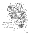
Fig. 1] Fig. 1 is an overall perspective view of a cutting machine provided with a dust collecting device according to an embodiment. - [
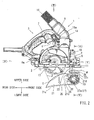
Fig. 2] Fig. 2 is a view as viewed in a direction of arrow (II) inFig. 1 and showing a front view of the cutting machine. - [
Fig. 3] Fig. 3 is a view as viewed in a direction of arrow (III) inFig. 2 and showing a plan view of the cutting machine. - [
Fig. 4] Fig. 4 is a view as viewed in a direction of arrow (IV) inFig. 2 ad showing a side view of the cutting machine when viewed from a rear side in the cut proceeding direction. - [
Fig. 5] Fig. 5 is a view as viewed in a direction of arrow (V) inFig. 2 and showing a side view of the cutting machine when viewed from a front side in the cut proceeding direction. - [
Fig. 6] Fig. 6 is a cross-sectional view taken along line (VI)-(VI) inFig. 2 and showing a view of the rear side of the cutting machine in the direction of the cut proceeding direction when viewed from the center of tilting movement of a powder dust receiver. - Next, description will be given of an embodiment of the present invention based on
Figs. 1 to 6 .Figs. 1 to 5 show an overall configuration of aportable cutting machine 1 provided with adust collecting device 20 according to this embodiment. The configuration of thecutting machine 1 itself is conventionally known, except for thedust collecting device 20, and description thereof will briefly be given since modifications are not particularly needed in this embodiment.
In addition, the user is positioned on the rear side of thecutting machine 1 inFig. 1 . In the following description, each of the front and rear, left and right, and up and down directions is defined with reference to the position of the user. Each direction is shown in the drawings.
Thecutting machine 1 is provided with a rectangular planer plate-shaped base 2, which is to be placed on the upper surface of a material W to be cut, and a cutting machinemain body 3 supported on the upper surface of thebase 2. The cutting machinemain body 3 is provided with anelectric motor 4 as a driving source and acircular cutting blade 5 rotated by theelectric motor 4. The circumference of thecutting blade 5 is covered with amain body case 6. Thecutting blade 5 is attached to aspindle 12 supported by themain body case 6. Thecutting blade 5 is rotated in the counterclockwise direction as indicated byarrow 6a that is shown on themain body case 6.
Theelectric motor 4 is attached to the back surface side (the left surface side) of themain body case 6. On the upper surface of theelectric motor 4, a loop-shapedhandle portion 7 is provided. As shown inFig. 2 , a triggertype switch lever 8, which is pulled and operated by the fingers of a user, is arranged on the inner circumferential side of thehandle portion 7. If theswitch lever 8 is pulled and operated, theelectric motor 4 is activated, and thecutting blade 5 is rotated. On the front and right side surface of thehandle portion 7 near the front side of theswitch lever 8, a push-buttontype illumination switch 9, which is turned on and off also with the fingers of the user, is arranged. If theillumination switch 9 is turned on, anillumination tool 10 provided at the front portion of themain body case 6 is turned on. A light emitting diode (LED) is used as theillumination tool 10. If theillumination tool 10 is turned on, a part near agauge portion 11 provided on the front end portion of thebase 2 for aligning with a cut line is brightly illuminated. By brightly illuminating the part near thegauge portion 11 with theillumination tool 10, it is possible to effectively perform a positioning operation (aligning with the cut line) of the material W to be cut in a dark place and to thereby quickly perform a cutting operation with precision. - At the front portion of the
main body case 6, adust collecting port 14 is provided. Thedust collecting port 14 is disposed on the upper side of a part (cutting part C) of thecutting blade 5, which is cut into the material W to be cut. The powder dust generated at the cutting part C is blown upwards within themain body case 6 due to the rotation of thecutting blade 5 and is caused to move into thedust collecting port 14. Adust collecting hose 15 is connected to thedust collecting port 14 via anozzle 15a, and a dust collecting machine (not shown in the drawings) is further connected via thedust connecting hose 15. The majority of the powder dust generated at the cutting part C is collected by the dust collecting machine. A small amount of powder dust that may remain in themain body case 6 without being collected by thedust collecting port 14 is blown rearward within themain body case 6 due to the rotation of thecutting blade 5. Thedust collecting port 14 on the side of themain body case 6 corresponds to the upper dust collecting port defined in the claims.
The lower portion of thecutting blade 5 protrudes toward the lower surface side via awindow portion 2a provided in thebase 2. The lower portion of thecutting blade 5 protruding toward the lower surface side of thebase 2 is covered with amovable cover 13. Themovable cover 13 is supported so as to rotatable along the circumference of thecutting blade 5. InFig. 2 , when themovable cover 13 is rotated in a clockwise direction and opened, the cutting edge of thecutting blade 5 is exposed. On the other hand, themovable cover 13 is biased by a spring in a closing direction. Themovable cover 13 is gradually opened against the biasing force of the spring as the cuttingmachine 1 moves forwardly with respect to the cut proceeding direction (the right side inFig. 2 ) to proceed the cutting operation of the material W to be cut, in a state where the tip end portion of themovable cover 13 contacts the end surface on the cutting side of the material W to be cut. Thedust collecting device 20 according to this embodiment has a configuration in which apowder dust receiver 21 is arranged on the lower side of themovable cover 13.
In addition, the cutting machinemain body 3 is supported so as to be capable of being vertically tiltable with respect to thebase 2, so that a cutting depth of thecutting blade 5 into the material W to be cut (a protruding amount from the lower surface of the base 2) is adjustable, and the cutting machinemain body 3 is supported so as to be also capable of being tiltable in the left and right direction, such that the material W to be cut can be cut in a so-called oblique cutting manner. This feature is based on a known technique of the related art, and therefore, the description thereof will be omitted. - The
dust collecting device 20 according to this embodiment is provided with thepowder dust receiver 21 and a supportingarm 22 supporting it with respect to thebase 2. Thepowder dust receiver 21 has a substantially box-like shape with an opened upper side and includes abottom plate portion 21a, left and rightside wall portions front wall portion 21d.
The supportingarm 22 is formed by bending a strip-shaped steel plate with a relatively narrow width into a U-shape and is fixed in a state where the supportingarm 22 extends toward the right side from a position closer to the front portion of thebase 2. The supportingarm 22 is fixed in a state where the supportingarm 22 perpendicularly intersects with the cut proceeding direction (the front and rear direction) by inserting theupper plate portion 22a into aninsertion hole 2b provided in the left side portion, which is closer to the front portion of thebase 2, and fixing thetip end portion 22b with a screw tighteningtype fixing lever 16 provided near the right side portion, which is also closer to the front portion of thebase 2. Since the fixed state of thetip end portion 22b is released if the fixinglever 16 is rotated in the screw loosening direction, it is possible to withdraw theupper plate portion 22a to the left side and to thereby remove thedust collecting device 20 from thebase 2.
Theinsertion hole 2b of thebase 2 and the fixinglever 16 are provided for mounting a ruler that guides the cuttingmachine 1 and eventually thecutting blade 5 in a parallel manner with a certain distance from an end surface of the material W to be cut, and this embodiment is characterized in the that thedust collecting device 20 is configured as an attachment type one that uses theinsertion hole 2b and the fixinglever 16 used for attaching the ruler (a ruler attachment portion) in order to enable thepowder dust receiver 21 to be mounted to and removed from the side of the cuttingmachine 1 with a simple operation.
Avertical plate portion 22c extends downward from the right end portion of theupper plate portion 22a of the supportingarm 22. Alower plate portion 22d extends rightward from the lower end portion of thevertical plate portion 22c. Thelower plate portion 22d extends so as to be parallel to theupper plate portion 22a. The material W to be cut moves into between theupper plate portion 22a and thelower plate portion 22d. For this reason, the length of thevertical plate portion 22c to the lower side (a distance between theupper plate portion 22a and thelower plate portion 22d) is set to a sufficiently long dimension to correspond to an expected plate thickness of the material W to be cut. - A projecting dimension of the
upper plate portion 22a to the right side (a projecting dimension from the right end portion of the base 2), namely the distance between thecutting blade 5 and thevertical plate portion 22c is also set to a sufficiently long dimension to correspond to an expected width of the material to be cut on the cutting-off side, which is to be cut off by the cutting operation.
A tubularcylindrical supporting member 24 is attached to the tip end portion (the right end portion) of thelower plate portion 22d via an L-shapedbracket 23. The cylindrical supportingmember 24 cannot be displaced in the axial direction with respect to thebracket 23 while being supported so as to be rotatable about the axis.
As shown inFig. 6 , aflange portion 24a is provided at the left end portion (the right end portion inFig. 6 ) of the cylindrical supportingmember 24. Apivot supporting portion 24b is provided between theflange portion 24a and thebracket 23. Aboss portion 21e integrally provided with the rightside wall portion 21c of thepowder dust receiver 21 is rotatably supported by thepivot supporting portion 24b. Theboss portion 21e is interposed between theflange portion 24a and thebracket 23 and supported so as not to be displaced in the axial direction.
As theboss portion 21e is pivotally supported by thepivot supporting portion 24b, thepowder dust receiver 21 is supported so as to be vertically tiltable with respect to the supportingarm 22. In this way, thecylindrical supporting member 24 is rotatably supported with respect to thebracket 23, theboss portion 21e of thepowder dust receiver 21 is rotatably supported by acylindrical supporting portion 24b of the cylindrical supportingmember 24, and the cylindrical supportingmember 24 and thepowder dust receiver 21 are supported by the supportingarm 22 so as to be rotatable about the same axial line independently of each other. As shown inFig. 2 , a position of the cylindrical supportingmember 24 with respect to the front and rear direction and eventually the shape of thebracket 23 are set such that the tilting center of the powder dust receiver 21 (the center axial of theboss portion 21e and thepivot supporting portion 24b) is positioned forwardly of the cutting part C. - In addition, the
bracket 23 is held between theboss portion 21e and a retainingring 25 so as to be coupled not to be relatively displaced in the axial direction. Thedust collecting hose 27 is connected to the right end portion of the cylindrical supportingmember 24 via thenozzle 27a. Thedust collecting hose 27 communicates with the inside of thepowder dust receiver 21 through an inner circumferential hole of the cylindrical supportingmember 24. The inner circumferential hole of the cylindrical supportingmember 24 corresponds to the lower dust collecting port defined in the claims.
A dust collecting machine not shown in the drawings is connected to thedust collecting hose 27. The powder dust in thepowder dust receiver 21 is forcibly collected by the dust collecting machine through thedust collecting hose 27 and the inner circumferential hole of the cylindrical supportingmember 24.
As described previously, thecylindrical supporting member 24 is fixed so as not to rotate with respect to thebracket 23. Thepowder dust receiver 21 is supported so as to be vertically tiltable with respect to the cylindrical supportingmember 24. Atension spring 26 is interposed between theright side wall 21c of thepowder dust receiver 21 and thebracket 23. Thepowder dust receiver 21 is biased in a direction, in which the tip end side with respect to the tilting movement is displaced upward, by thetension spring 26. As shown inFig. 2 , astopper block 28 is attached to the rightside wall portion 21c of thepowder dust receiver 21. Thestopper block 28 contacts thebracket 23, and thepowder dust receiver 21 is held at an upper receiving position. The receiving position of thepowder dust receiver 21 restricted by thestopper block 28 is set to a position where thefront wall portion 21 d is substantially upright and thebottom plate portion 21a is inclined in a direction slightly downward to the rear side from a horizontal position, as shown inFig. 2 .
Thepowder dust receiver 21 can be tilted in a direction in which the rear portion side thereof is displaced downward from the upper receiving position (a direction indicated by outline arrow inFig. 2 ; hereinafter, referred to as a discharge direction). Thepowder dust receiver 21 is tilted in the discharge direction against thetension spring 26. In addition, thepowder dust receiver 21 is vertically tilted about the axial of theboss portion 21e (the axial of the cylindrical supporting member 24). - As shown in
Fig. 6 , thepowder dust receiver 21 is held on the lower side of thecutting blade 5. For this reason, the leftside wall portion 21b is positioned on the left side of the cutting plane S including thecutting blade 5, and the rightside wall portion 21c is positioned on the right side. Since the left and rightside wall portions bottom plate portion 21a is arranged between the lower end portions thereof, it is possible to effectively receive the powder dust scattered to the lower side of the material W to be cut.
Here, on the side of the rear end portion of the cutting blade 5 (the rear side intersecting portion of two front and rear intersecting portions between the material W to be cut and the cutting edge of the cutting blade 5 (the front intersecting portion corresponds to the cutting part C)), a small amount of the powder dust is blown to the lower surface side of the material W to be cut due to contact of the cutting edge of thecutting blade 5 with a kerf of the material W to be cut, for example. In addition, the majority of the powder dust blown upward from the cutting part C is collected by thedust collecting hose 15 through thedust collecting port 14 of themain body case 6, and remaining powder dust, which cannot be collected, is blown to the lower surface side of the material W to be cut after being blown to the rear side within themain body case 6 by the rotation of thecutting blade 5. The powder dust blown to the lower surface side of the material W to be cut is blown downward from the tip end portion of themovable cover 13 through inside of themovable cover 13 that is in the course of opening or in a fully opened state. When the cutting operation proceeds, and themovable cover 13 is in the fully opened state, the powder dust is blown downward from the rear side intersecting portion between the lower surface of thebase 2 and the cutting blade 5 (the position of the tip end portion of the movable cover 13) along a tangential direction indicated by axial J inFig. 2 .
In this way, the lengths in the front and rear direction of thebottom plate portion 21a, the left and rightside wall portions powder dust receiver 21 are set such that thebottom plate portion 21a, the left and rightside wall portions powder dust receiver 21 are positioned on the lower side of the tip end portion of themovable cover 13 throughout the entire open and close range of themovable cover 13. For this reason, also the powder dust blown from the side of the rear portion of thecutting blade 5 to the lower surface side of the material W to be cut can be reliably collected by thepowder dust receiver 21.
As shown inFig. 2 , the upper portions of the left and rightside wall portions powder dust receiver 21 are respectively formed in arc shapes curved in a direction inclined downward toward the rear side. In addition, as described previously, thepowder dust receiver 21 is vertically tiltably supported about the axial of the cylindrical supportingmember 24. For this reason, when the cutting process is completed, and the cutting-off side part, which has been cut from the main body side part of the material to be cut, leans against the left and rightside wall portions powder dust receiver 21 is tilted in the discharge direction indicated by outlined arrow inFig. 2 against the biasing force of thetension spring 26 due to the weight thereof. Particularly, the upper portions of the left and rightside wall portions powder dust receiver 21 are formed in arc shapes in the direction inclined downward toward the rear side. For this reason, the cutting-off side part of the material to be cut, which leans against the left and rightside wall portions side wall portions powder dust receiver 21 is tilted in the discharge direction.
Since the cutting-off side part of the material to be cut reliably slips down from thepowder dust receiver 21 and is not held in a leaning state as described above, the cutting-off side part is separated by a sufficient distance from the main body side part of the material to be cut after completion of the cutting process, and as a result, the cutting-off side part does not interfere with the movement of themovable cover 13 for returning to a fully closed state, and themovable cover 13 smoothly returns to the fully closed position by the spring biasing force. - According to the
dust collecting device 20 of this embodiment configured as described above, it is possible to collect the powder dust generated or scattered on the lower surface side of the material W to be cut substantially directly below thecutting blade 5 by thepowder dust receiver 21, to thereby improve the dust collecting function for the cuttingmachine 1, and thus to further improve the working environment. Particularly, by using the dust collecting functions on the side of the main body case 6 (thedust collecting port 14, thedust collecting hose 15, and the like) together, it is possible to further improve the dust collecting function of the cuttingmachine 1.
In addition, according to thedust collecting device 20 of this embodiment, thepowder dust receiver 21 is supported by thebase 2 via the supportingarm 22, and therefore, it is possible to handle this as an integral part with the cuttingmachine 1 and to thereby further enhance convenience in handling thedust collecting device 20 as compared with the conventional one.
Furthermore, by loosening the fixinglever 16 of thebase 2, it is possible to withdraw theupper plate portion 22a of the supportingarm 22 out from theinsertion hole 2b and to remove thedust collecting device 20 from the cuttingmachine 1. Thus, it is possible to remove thedust collecting device 20 if unnecessary, in order to use the cuttingmachine 1 as a separate machine, and therefore, it is possible to secure the handling property of the cuttingmachine 1 as a separate machine.
In addition, thedust collecting device 20 according to this embodiment is configured to be attached with the use of the ruler attachment portions of the base 2(theinsertion hole 2b and the screw tightening type fixing lever 16), and therefore, it is possible to realize thedust collecting device 20 at a lower cost as compared with the case where a special attachment portion is newly set, and additionally, it is possible to easily attach thedust collecting device 20 later.
In addition, according to the exemplifieddust collecting device 20, thepowder dust receiver 21 is provided so as to be vertically tiltable while the upper portions of the left and rightside wall portions powder dust receiver 21. For this reason, the cutting-off side part of the material to be cut does not interfere with the returning movement of themovable cover 13 to the fully closed state, and the movable cover is smoothly and reliably returned to the fully closed position due to the spring biasing force.
In addition, thepowder dust receiver 21 is supported so as to be vertically tiltable with respect to the cylindrical supportingmember 24 to which thedust collecting hose 27 is connected. For this reason, thepowder dust receiver 21 can smoothly vertically be tilted without causing thedust collecting hose 27 to be twisted, and therefore, the cutting-off side part of the material to be cut can reliably slip down from thepowder dust receiver 21, thepowder dust receiver 21 can be reliably returned to the receiving position by thetension spring 26, and it is possible to secure the reliability of the movement of thepowder dust receiver 21, in this regard. - Various modifications can be made to the embodiment described above. In relation to the supporting
arm 22, for example, it is possible to configure the position of thevertical plate portion 22c in the horizontal direction to be changeable without changing the horizontal position of thepowder dust receiver 21 with respect to thecutting blade 5 by configuring the positions of theupper plate portion 22a and thelower plate portion 22d or the lengths thereof to be changeable. By configuring the horizontal position of thevertical plate portion 22c to be changeable, it is possible to easily handle a variation in the width dimension of the cutting-off side part of the material to be cut while the supportingarm 22 is downsized.
In addition, by configuring the length of thevertical plate portion 22c of the supportingarm 22 to be adjustable, it is possible to adjust the vertical position of thepowder dust receiver 21 with respect to thecutting blade 5 and to change the distance between theupper plate portion 22a and thelower plate portion 22d in accordance with a variation in the plate thickness of the material W to be cut.
Thedust collecting hose 15 connected to the side of themain body case 6 and thedust collecting hose 27 connected to the side of thepowder dust receiver 21 can be configured to be connected to each other for connecting to a single dust collecting machine.
The connection of thedust collecting hose 27 and the dust collecting machine to thepowder dust receiver 21 may be omitted. In such a case, it is possible to achieve the same functions and effects of collecting dust on the lower surface side of the material to be cut by performing a discharge operation of powder dust received by thepowder dust receiver 21 at an appropriate time by the user.
In addition, although a configuration was exemplified in which the attachment is performed with the use of the ruler attachment portions (theinsertion hole 2b and the fixing lever 16) of thebase 2, a configuration is also applicable in which the dust collecting device is attached by newly providing special attachment means at thebase 2 or another part of the cutting machinemain body 3.
Furthermore, although a configuration was exemplified in which thedust collecting device 20 can completely be removed from thebase 2, a configuration is also applicable in which a vertically pivoting function is provided to the supporting arm, for example, such that the powder dust receiver can retreat upward without being removed.
Claims (8)
- A dust collecting device provided on a cutting machine having a base to be placed on a material to be cut and a cutting machine main body that is supported on an upper surface of the base and is provided with a circular cutting blade protruding to a lower surface side of the base, the cutting machine main body being moved together with the base in a cut proceeding direction for performing a cutting operation of a material to be cut, the dust collecting device comprising:a powder dust receiver supported on the base or the cutting machine main body and held on the lower side of the cutting blade.
- The dust collecting device according to Claim 1,
wherein the powder dust receiver is removably supported with respect to the base or the cutting machine main body. - The dust collecting device according to Claim 2,
wherein the powder dust receiver is removably supported by the base. - The dust collecting device according to Claim 3,
wherein the base is provided with a ruler attachment portion to which a parallel ruler guiding the cutting blade with respect to the material to be cut is attached, and the powder dust receiver is supported via a supporting arm attached with the use of the ruler attachment portion. - The dust collecting device according to Claim 2,
wherein the powder dust receiver is vertically tiltably supported. - The dust collecting device according to Claim 5,
wherein the powder dust receiver is provided with a dust collecting nozzle for connecting a dust collecting hose and is supported so as to be vertically tiltable with respect to the dust collecting nozzle. - A cutting machine comprising the dust collecting device according to any one of Claims 1 to 6.
- A cutting machine comprising the dust collecting device according to Claim 1,
wherein the powder dust receiver is provided with a lower dust collecting port for connecting with a dust collecting hose,
wherein the circumference of the cutting blade is covered with a main body case on a side of an upper surface of the base, and
wherein the main body case is provided with an upper dust collecting port for connecting with a dust collecting hose.
Applications Claiming Priority (2)
| Application Number | Priority Date | Filing Date | Title |
|---|---|---|---|
| JP2009257961A JP5468360B2 (en) | 2009-11-11 | 2009-11-11 | Dust collector of cutting machine |
| PCT/JP2010/069808 WO2011058942A1 (en) | 2009-11-11 | 2010-11-08 | Dust collector for cutting machine |
Publications (3)
| Publication Number | Publication Date |
|---|---|
| EP2500125A1 true EP2500125A1 (en) | 2012-09-19 |
| EP2500125A4 EP2500125A4 (en) | 2015-08-05 |
| EP2500125B1 EP2500125B1 (en) | 2020-03-04 |
Family
ID=43991601
Family Applications (1)
| Application Number | Title | Priority Date | Filing Date |
|---|---|---|---|
| EP10829901.7A Active EP2500125B1 (en) | 2009-11-11 | 2010-11-08 | Cutting machine with a dust collector |
Country Status (4)
| Country | Link |
|---|---|
| EP (1) | EP2500125B1 (en) |
| JP (1) | JP5468360B2 (en) |
| CN (1) | CN102665985B (en) |
| WO (1) | WO2011058942A1 (en) |
Cited By (2)
| Publication number | Priority date | Publication date | Assignee | Title |
|---|---|---|---|---|
| CN103029188A (en) * | 2012-12-29 | 2013-04-10 | 烟台盖恩机械设备有限公司 | Full-automatic eyebrow pencil end cropping and sharpening machine |
| US10722960B2 (en) | 2017-02-22 | 2020-07-28 | Makita Corporation | Cutting device |
Families Citing this family (5)
| Publication number | Priority date | Publication date | Assignee | Title |
|---|---|---|---|---|
| CN107116635B (en) * | 2017-05-19 | 2022-12-09 | 无锡市宏晨电工机械有限公司 | Wood board cutting machine with function of absorbing wood chips by triboelectrification |
| DE102019134415B4 (en) * | 2019-12-13 | 2023-12-14 | Festool Gmbh | Mobile hand sawing machine with scoring unit and dust removal |
| JP7476014B2 (en) * | 2020-03-18 | 2024-04-30 | 株式会社マキタ | Portable cutting machine for masonry |
| WO2021083411A2 (en) * | 2020-12-18 | 2021-05-06 | 苏州普轮电子科技有限公司 | Seenvironmentally friendly and energy-saving cutting machine |
| CN113681070B (en) * | 2021-10-27 | 2021-12-31 | 江苏振乾机电科技有限公司 | Portable pneumatic cutting machine |
Family Cites Families (12)
| Publication number | Priority date | Publication date | Assignee | Title |
|---|---|---|---|---|
| DE2404872B2 (en) * | 1974-02-01 | 1976-12-09 | Black & Decker Gmbh, 6270 Idstein | PORTABLE MACHINE TOOL FOR CUTTING STONE, ASBESTOS CEMENT, O.AE. -PLATES |
| JPS5247380U (en) * | 1975-10-01 | 1977-04-04 | ||
| JPS5662101A (en) * | 1979-10-26 | 1981-05-27 | Yamada Ind | Dust collector for electric saw |
| JPS56109819U (en) * | 1980-01-18 | 1981-08-25 | ||
| JPS60127902U (en) * | 1984-02-08 | 1985-08-28 | 清水建設株式会社 | saw |
| JPH037129Y2 (en) * | 1987-01-30 | 1991-02-22 | ||
| JPS63179020U (en) * | 1987-05-12 | 1988-11-18 | ||
| JPH0742643Y2 (en) * | 1989-11-16 | 1995-10-04 | リョービ株式会社 | Circular saw device with variable cutting angle |
| JPH08309616A (en) * | 1995-05-15 | 1996-11-26 | Shinichi Fujimoto | Double-blade type tube vertical cutting jig |
| GB2362128A (en) * | 2000-04-17 | 2001-11-14 | Anthony Ian Pinder | Shoe cum shroud for a hand held circular saw |
| JP2002210702A (en) | 2001-01-19 | 2002-07-30 | Makita Corp | Dust collecting ruler |
| JP2009179050A (en) * | 2008-02-01 | 2009-08-13 | Hitachi Koki Co Ltd | Bench cutter |
-
2009
- 2009-11-11 JP JP2009257961A patent/JP5468360B2/en active Active
-
2010
- 2010-11-08 CN CN201080058201.7A patent/CN102665985B/en active Active
- 2010-11-08 WO PCT/JP2010/069808 patent/WO2011058942A1/en active Application Filing
- 2010-11-08 EP EP10829901.7A patent/EP2500125B1/en active Active
Non-Patent Citations (1)
| Title |
|---|
| See references of WO2011058942A1 * |
Cited By (3)
| Publication number | Priority date | Publication date | Assignee | Title |
|---|---|---|---|---|
| CN103029188A (en) * | 2012-12-29 | 2013-04-10 | 烟台盖恩机械设备有限公司 | Full-automatic eyebrow pencil end cropping and sharpening machine |
| CN103029188B (en) * | 2012-12-29 | 2015-09-09 | 烟台盖恩机械设备有限公司 | A kind of full-automatic eyebrow pencil back-end crop sharpener |
| US10722960B2 (en) | 2017-02-22 | 2020-07-28 | Makita Corporation | Cutting device |
Also Published As
| Publication number | Publication date |
|---|---|
| EP2500125B1 (en) | 2020-03-04 |
| EP2500125A4 (en) | 2015-08-05 |
| WO2011058942A1 (en) | 2011-05-19 |
| CN102665985B (en) | 2014-12-31 |
| JP2011101929A (en) | 2011-05-26 |
| JP5468360B2 (en) | 2014-04-09 |
| CN102665985A (en) | 2012-09-12 |
Similar Documents
| Publication | Publication Date | Title |
|---|---|---|
| EP2500125B1 (en) | Cutting machine with a dust collector | |
| US8919235B2 (en) | Cutting apparatus | |
| US5927171A (en) | Bench circular saw machine | |
| GB2441031A (en) | A hand-held circular saw with angularly adjustable guide plate | |
| US20140013911A1 (en) | Cutting tools | |
| JP4244615B2 (en) | Electric cutting machine | |
| JP2009143129A (en) | Bench cutting machine and dust collector for bench cutting machine | |
| JP4847098B2 (en) | Cutting machine | |
| EP2436494B1 (en) | Cutting machine with a safety cover | |
| US20070289424A1 (en) | Workpiece-holding device for band saw machine | |
| JP5240672B2 (en) | Cutting tool | |
| JP4936220B2 (en) | Electric tool | |
| US10668644B2 (en) | Portable cutting devices | |
| JP2008073920A (en) | Table cutter | |
| JP5792329B2 (en) | Dust collector of cutting machine | |
| JP5240671B2 (en) | Cutting tool | |
| JP7438828B2 (en) | portable cutting machine | |
| JP3899311B2 (en) | Cutting machine | |
| JP2003048118A (en) | Cutter | |
| JP4177066B2 (en) | Cutting machine | |
| JPH11170214A (en) | Chip guiding device for slide type table cutter | |
| JP4990091B2 (en) | Sliding cutting machine | |
| JP3674372B2 (en) | Tabletop cutting machine | |
| JP2017213647A (en) | Cutting machine | |
| JP2005074798A (en) | Circular saw |
Legal Events
| Date | Code | Title | Description |
|---|---|---|---|
| PUAI | Public reference made under article 153(3) epc to a published international application that has entered the european phase |
Free format text: ORIGINAL CODE: 0009012 |
|
| 17P | Request for examination filed |
Effective date: 20120510 |
|
| AK | Designated contracting states |
Kind code of ref document: A1 Designated state(s): AL AT BE BG CH CY CZ DE DK EE ES FI FR GB GR HR HU IE IS IT LI LT LU LV MC MK MT NL NO PL PT RO RS SE SI SK SM TR |
|
| DAX | Request for extension of the european patent (deleted) | ||
| RA4 | Supplementary search report drawn up and despatched (corrected) |
Effective date: 20150707 |
|
| RIC1 | Information provided on ipc code assigned before grant |
Ipc: B27B 9/00 20060101ALI20150701BHEP Ipc: B23D 45/16 20060101ALI20150701BHEP Ipc: B27G 3/00 20060101ALI20150701BHEP Ipc: B23D 59/00 20060101ALI20150701BHEP Ipc: B23D 47/00 20060101AFI20150701BHEP |
|
| STAA | Information on the status of an ep patent application or granted ep patent |
Free format text: STATUS: EXAMINATION IS IN PROGRESS |
|
| 17Q | First examination report despatched |
Effective date: 20170818 |
|
| GRAP | Despatch of communication of intention to grant a patent |
Free format text: ORIGINAL CODE: EPIDOSNIGR1 |
|
| STAA | Information on the status of an ep patent application or granted ep patent |
Free format text: STATUS: GRANT OF PATENT IS INTENDED |
|
| INTG | Intention to grant announced |
Effective date: 20191111 |
|
| GRAS | Grant fee paid |
Free format text: ORIGINAL CODE: EPIDOSNIGR3 |
|
| GRAJ | Information related to disapproval of communication of intention to grant by the applicant or resumption of examination proceedings by the epo deleted |
Free format text: ORIGINAL CODE: EPIDOSDIGR1 |
|
| GRAL | Information related to payment of fee for publishing/printing deleted |
Free format text: ORIGINAL CODE: EPIDOSDIGR3 |
|
| STAA | Information on the status of an ep patent application or granted ep patent |
Free format text: STATUS: EXAMINATION IS IN PROGRESS |
|
| GRAR | Information related to intention to grant a patent recorded |
Free format text: ORIGINAL CODE: EPIDOSNIGR71 |
|
| STAA | Information on the status of an ep patent application or granted ep patent |
Free format text: STATUS: GRANT OF PATENT IS INTENDED |
|
| GRAA | (expected) grant |
Free format text: ORIGINAL CODE: 0009210 |
|
| STAA | Information on the status of an ep patent application or granted ep patent |
Free format text: STATUS: THE PATENT HAS BEEN GRANTED |
|
| INTC | Intention to grant announced (deleted) | ||
| AK | Designated contracting states |
Kind code of ref document: B1 Designated state(s): AL AT BE BG CH CY CZ DE DK EE ES FI FR GB GR HR HU IE IS IT LI LT LU LV MC MK MT NL NO PL PT RO RS SE SI SK SM TR |
|
| INTG | Intention to grant announced |
Effective date: 20200124 |
|
| REG | Reference to a national code |
Ref country code: GB Ref legal event code: FG4D |
|
| REG | Reference to a national code |
Ref country code: CH Ref legal event code: EP |
|
| REG | Reference to a national code |
Ref country code: AT Ref legal event code: REF Ref document number: 1239821 Country of ref document: AT Kind code of ref document: T Effective date: 20200315 |
|
| REG | Reference to a national code |
Ref country code: DE Ref legal event code: R096 Ref document number: 602010063369 Country of ref document: DE |
|
| REG | Reference to a national code |
Ref country code: IE Ref legal event code: FG4D |
|
| PG25 | Lapsed in a contracting state [announced via postgrant information from national office to epo] |
Ref country code: NO Free format text: LAPSE BECAUSE OF FAILURE TO SUBMIT A TRANSLATION OF THE DESCRIPTION OR TO PAY THE FEE WITHIN THE PRESCRIBED TIME-LIMIT Effective date: 20200604 Ref country code: RS Free format text: LAPSE BECAUSE OF FAILURE TO SUBMIT A TRANSLATION OF THE DESCRIPTION OR TO PAY THE FEE WITHIN THE PRESCRIBED TIME-LIMIT Effective date: 20200304 Ref country code: FI Free format text: LAPSE BECAUSE OF FAILURE TO SUBMIT A TRANSLATION OF THE DESCRIPTION OR TO PAY THE FEE WITHIN THE PRESCRIBED TIME-LIMIT Effective date: 20200304 |
|
| REG | Reference to a national code |
Ref country code: NL Ref legal event code: MP Effective date: 20200304 |
|
| PG25 | Lapsed in a contracting state [announced via postgrant information from national office to epo] |
Ref country code: HR Free format text: LAPSE BECAUSE OF FAILURE TO SUBMIT A TRANSLATION OF THE DESCRIPTION OR TO PAY THE FEE WITHIN THE PRESCRIBED TIME-LIMIT Effective date: 20200304 Ref country code: GR Free format text: LAPSE BECAUSE OF FAILURE TO SUBMIT A TRANSLATION OF THE DESCRIPTION OR TO PAY THE FEE WITHIN THE PRESCRIBED TIME-LIMIT Effective date: 20200605 Ref country code: SE Free format text: LAPSE BECAUSE OF FAILURE TO SUBMIT A TRANSLATION OF THE DESCRIPTION OR TO PAY THE FEE WITHIN THE PRESCRIBED TIME-LIMIT Effective date: 20200304 Ref country code: LV Free format text: LAPSE BECAUSE OF FAILURE TO SUBMIT A TRANSLATION OF THE DESCRIPTION OR TO PAY THE FEE WITHIN THE PRESCRIBED TIME-LIMIT Effective date: 20200304 Ref country code: BG Free format text: LAPSE BECAUSE OF FAILURE TO SUBMIT A TRANSLATION OF THE DESCRIPTION OR TO PAY THE FEE WITHIN THE PRESCRIBED TIME-LIMIT Effective date: 20200604 |
|
| REG | Reference to a national code |
Ref country code: LT Ref legal event code: MG4D |
|
| PG25 | Lapsed in a contracting state [announced via postgrant information from national office to epo] |
Ref country code: NL Free format text: LAPSE BECAUSE OF FAILURE TO SUBMIT A TRANSLATION OF THE DESCRIPTION OR TO PAY THE FEE WITHIN THE PRESCRIBED TIME-LIMIT Effective date: 20200304 |
|
| PG25 | Lapsed in a contracting state [announced via postgrant information from national office to epo] |
Ref country code: EE Free format text: LAPSE BECAUSE OF FAILURE TO SUBMIT A TRANSLATION OF THE DESCRIPTION OR TO PAY THE FEE WITHIN THE PRESCRIBED TIME-LIMIT Effective date: 20200304 Ref country code: LT Free format text: LAPSE BECAUSE OF FAILURE TO SUBMIT A TRANSLATION OF THE DESCRIPTION OR TO PAY THE FEE WITHIN THE PRESCRIBED TIME-LIMIT Effective date: 20200304 Ref country code: SM Free format text: LAPSE BECAUSE OF FAILURE TO SUBMIT A TRANSLATION OF THE DESCRIPTION OR TO PAY THE FEE WITHIN THE PRESCRIBED TIME-LIMIT Effective date: 20200304 Ref country code: RO Free format text: LAPSE BECAUSE OF FAILURE TO SUBMIT A TRANSLATION OF THE DESCRIPTION OR TO PAY THE FEE WITHIN THE PRESCRIBED TIME-LIMIT Effective date: 20200304 Ref country code: PT Free format text: LAPSE BECAUSE OF FAILURE TO SUBMIT A TRANSLATION OF THE DESCRIPTION OR TO PAY THE FEE WITHIN THE PRESCRIBED TIME-LIMIT Effective date: 20200729 Ref country code: CZ Free format text: LAPSE BECAUSE OF FAILURE TO SUBMIT A TRANSLATION OF THE DESCRIPTION OR TO PAY THE FEE WITHIN THE PRESCRIBED TIME-LIMIT Effective date: 20200304 Ref country code: ES Free format text: LAPSE BECAUSE OF FAILURE TO SUBMIT A TRANSLATION OF THE DESCRIPTION OR TO PAY THE FEE WITHIN THE PRESCRIBED TIME-LIMIT Effective date: 20200304 Ref country code: SK Free format text: LAPSE BECAUSE OF FAILURE TO SUBMIT A TRANSLATION OF THE DESCRIPTION OR TO PAY THE FEE WITHIN THE PRESCRIBED TIME-LIMIT Effective date: 20200304 Ref country code: IS Free format text: LAPSE BECAUSE OF FAILURE TO SUBMIT A TRANSLATION OF THE DESCRIPTION OR TO PAY THE FEE WITHIN THE PRESCRIBED TIME-LIMIT Effective date: 20200704 |
|
| REG | Reference to a national code |
Ref country code: AT Ref legal event code: MK05 Ref document number: 1239821 Country of ref document: AT Kind code of ref document: T Effective date: 20200304 |
|
| REG | Reference to a national code |
Ref country code: DE Ref legal event code: R097 Ref document number: 602010063369 Country of ref document: DE |
|
| PLBE | No opposition filed within time limit |
Free format text: ORIGINAL CODE: 0009261 |
|
| STAA | Information on the status of an ep patent application or granted ep patent |
Free format text: STATUS: NO OPPOSITION FILED WITHIN TIME LIMIT |
|
| PG25 | Lapsed in a contracting state [announced via postgrant information from national office to epo] |
Ref country code: IT Free format text: LAPSE BECAUSE OF FAILURE TO SUBMIT A TRANSLATION OF THE DESCRIPTION OR TO PAY THE FEE WITHIN THE PRESCRIBED TIME-LIMIT Effective date: 20200304 Ref country code: AT Free format text: LAPSE BECAUSE OF FAILURE TO SUBMIT A TRANSLATION OF THE DESCRIPTION OR TO PAY THE FEE WITHIN THE PRESCRIBED TIME-LIMIT Effective date: 20200304 Ref country code: DK Free format text: LAPSE BECAUSE OF FAILURE TO SUBMIT A TRANSLATION OF THE DESCRIPTION OR TO PAY THE FEE WITHIN THE PRESCRIBED TIME-LIMIT Effective date: 20200304 |
|
| 26N | No opposition filed |
Effective date: 20201207 |
|
| PG25 | Lapsed in a contracting state [announced via postgrant information from national office to epo] |
Ref country code: SI Free format text: LAPSE BECAUSE OF FAILURE TO SUBMIT A TRANSLATION OF THE DESCRIPTION OR TO PAY THE FEE WITHIN THE PRESCRIBED TIME-LIMIT Effective date: 20200304 Ref country code: PL Free format text: LAPSE BECAUSE OF FAILURE TO SUBMIT A TRANSLATION OF THE DESCRIPTION OR TO PAY THE FEE WITHIN THE PRESCRIBED TIME-LIMIT Effective date: 20200304 |
|
| PG25 | Lapsed in a contracting state [announced via postgrant information from national office to epo] |
Ref country code: MC Free format text: LAPSE BECAUSE OF FAILURE TO SUBMIT A TRANSLATION OF THE DESCRIPTION OR TO PAY THE FEE WITHIN THE PRESCRIBED TIME-LIMIT Effective date: 20200304 |
|
| REG | Reference to a national code |
Ref country code: CH Ref legal event code: PL |
|
| GBPC | Gb: european patent ceased through non-payment of renewal fee |
Effective date: 20201108 |
|
| PG25 | Lapsed in a contracting state [announced via postgrant information from national office to epo] |
Ref country code: LU Free format text: LAPSE BECAUSE OF NON-PAYMENT OF DUE FEES Effective date: 20201108 |
|
| REG | Reference to a national code |
Ref country code: BE Ref legal event code: MM Effective date: 20201130 |
|
| PG25 | Lapsed in a contracting state [announced via postgrant information from national office to epo] |
Ref country code: LI Free format text: LAPSE BECAUSE OF NON-PAYMENT OF DUE FEES Effective date: 20201130 Ref country code: CH Free format text: LAPSE BECAUSE OF NON-PAYMENT OF DUE FEES Effective date: 20201130 |
|
| PG25 | Lapsed in a contracting state [announced via postgrant information from national office to epo] |
Ref country code: FR Free format text: LAPSE BECAUSE OF NON-PAYMENT OF DUE FEES Effective date: 20201130 Ref country code: IE Free format text: LAPSE BECAUSE OF NON-PAYMENT OF DUE FEES Effective date: 20201108 |
|
| PG25 | Lapsed in a contracting state [announced via postgrant information from national office to epo] |
Ref country code: GB Free format text: LAPSE BECAUSE OF NON-PAYMENT OF DUE FEES Effective date: 20201108 |
|
| PG25 | Lapsed in a contracting state [announced via postgrant information from national office to epo] |
Ref country code: TR Free format text: LAPSE BECAUSE OF FAILURE TO SUBMIT A TRANSLATION OF THE DESCRIPTION OR TO PAY THE FEE WITHIN THE PRESCRIBED TIME-LIMIT Effective date: 20200304 Ref country code: MT Free format text: LAPSE BECAUSE OF FAILURE TO SUBMIT A TRANSLATION OF THE DESCRIPTION OR TO PAY THE FEE WITHIN THE PRESCRIBED TIME-LIMIT Effective date: 20200304 Ref country code: CY Free format text: LAPSE BECAUSE OF FAILURE TO SUBMIT A TRANSLATION OF THE DESCRIPTION OR TO PAY THE FEE WITHIN THE PRESCRIBED TIME-LIMIT Effective date: 20200304 |
|
| PG25 | Lapsed in a contracting state [announced via postgrant information from national office to epo] |
Ref country code: MK Free format text: LAPSE BECAUSE OF FAILURE TO SUBMIT A TRANSLATION OF THE DESCRIPTION OR TO PAY THE FEE WITHIN THE PRESCRIBED TIME-LIMIT Effective date: 20200304 Ref country code: AL Free format text: LAPSE BECAUSE OF FAILURE TO SUBMIT A TRANSLATION OF THE DESCRIPTION OR TO PAY THE FEE WITHIN THE PRESCRIBED TIME-LIMIT Effective date: 20200304 |
|
| PG25 | Lapsed in a contracting state [announced via postgrant information from national office to epo] |
Ref country code: BE Free format text: LAPSE BECAUSE OF NON-PAYMENT OF DUE FEES Effective date: 20201130 |
|
| PGFP | Annual fee paid to national office [announced via postgrant information from national office to epo] |
Ref country code: DE Payment date: 20230929 Year of fee payment: 14 |