EP2037699A1 - Echo suppressor - Google Patents
Echo suppressor Download PDFInfo
- Publication number
- EP2037699A1 EP2037699A1 EP07744111A EP07744111A EP2037699A1 EP 2037699 A1 EP2037699 A1 EP 2037699A1 EP 07744111 A EP07744111 A EP 07744111A EP 07744111 A EP07744111 A EP 07744111A EP 2037699 A1 EP2037699 A1 EP 2037699A1
- Authority
- EP
- European Patent Office
- Prior art keywords
- signals
- echo
- microphones
- loudspeakers
- echo suppressor
- Prior art date
- Legal status (The legal status is an assumption and is not a legal conclusion. Google has not performed a legal analysis and makes no representation as to the accuracy of the status listed.)
- Withdrawn
Links
Images


Classifications
-
- H—ELECTRICITY
- H04—ELECTRIC COMMUNICATION TECHNIQUE
- H04M—TELEPHONIC COMMUNICATION
- H04M9/00—Arrangements for interconnection not involving centralised switching
- H04M9/08—Two-way loud-speaking telephone systems with means for conditioning the signal, e.g. for suppressing echoes for one or both directions of traffic
- H04M9/082—Two-way loud-speaking telephone systems with means for conditioning the signal, e.g. for suppressing echoes for one or both directions of traffic using echo cancellers
-
- H—ELECTRICITY
- H04—ELECTRIC COMMUNICATION TECHNIQUE
- H04R—LOUDSPEAKERS, MICROPHONES, GRAMOPHONE PICK-UPS OR LIKE ACOUSTIC ELECTROMECHANICAL TRANSDUCERS; ELECTRIC HEARING AIDS; PUBLIC ADDRESS SYSTEMS
- H04R3/00—Circuits for transducers
- H04R3/02—Circuits for transducers for preventing acoustic reaction, i.e. acoustic oscillatory feedback
Definitions
- the present invention relates to an echo suppressor operable to suppress echoes received by microphones from loudspeakers.
- a conventional echo suppressor suppresses echoes by calculating cross spectrum between signals from microphones and the reference signals, and estimating spatial transfer characteristics between the loudspeakers and the microphones by using addition signals and subtraction signals calculated as reference signals from sound signals inputted into right and left channel loudspeakers (see, for example, Patent document 1).
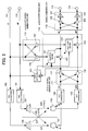
- FIG. 3 is a block diagram showing a conventional echo suppressor disclosed in patent document 1. Two microphones and two loudspeakers are arranged as shown in FIG. 3 . The construction of the conventional echo suppressor shown in FIG. 3 will be described hereinafter.
- the right and left channel stereo signals are respectively inputted into D/A converters 303 and 304 through input terminals 301 and 302 .
- the digital-to-analog conversions of the right and left channel stereo signals are performed by the D/A converters 303 and 304 , while the loudspeakers 305 and 306 output sounds represented by analog signals outputted from the D/A converters 303 and 304 .
- the sounds outputted from the loudspeakers 305 and 306 are received as echoes by the microphones 307 and 308 through spatial transfer paths hLL, hLR, hRL, and hRR , while analog-to-digital conversions of signals indicative of the sounds are performed by the A/D converters 309 and 310 .
- the addition/subtraction signal generating unit 321 generates an addition signal and a subtraction signal from the signals received through the input terminals 301 and 302 by using an adder 322 and a subtracter 323 , while the correlation detecting unit 325 detects a correlation from the addition signal and the subtraction signal.
- the transfer function calculating unit 324 estimates spatial transfer characteristics between the loudspeakers and the microphones. More specifically, the transfer function calculating unit 324 performs a cross-spectral analysis of output signals from the subtracters 319 and 320 , and output signals from the addition/subtraction signal generating unit 321.
- the filters 313, 314, 315, and 316 replicate spatial transfer characteristics hLL, hLR, hRL , and hRR corresponding to spatial transfer paths between loudspeakers 305, 306 and microphones 307 , 308 by using coefficients calculated by a transfer function calculating unit 324.
- An adder 317 generates a replica echo signal by adding one of signals outputted from the filters 313 and 314 to the other of the signals outputted from the filters 313 and 314 .
- An adder 318 generates a replica echo signal by adding one of signals outputted from the filters 315 and 316 to the other of the signals outputted from the filters 315 and 316.
- a subtracter 319 suppresses an echo forming part of a signal to be outputted to an output terminal 311 by subtracting the replica echo signal outputted from the adder 317 from the digital signal outputted from the A/D converter 309 .
- a subtracter 320 suppresses an echo forming part of a signal to be outputted to an output terminal 312 by subtracting the replica echo signal outputted from the adder 318 from the digital signal outputted from the A/D converter 310 .
- Patent document 1 Japanese Patent Laying-Open Publication No. 2003-102085 (page 56, FIG. 1 )
- the conventional echo suppressor however encounters such a problem that the number of spatial transfer paths necessary to estimate and replicate spatial transfer characteristics increases with the number of loudspeakers and the number of microphones. Therefore, the conventional echo suppressor is required to perform complex calculations necessary to suppress echoes. The amount of calculations increases with the number of spatial transfer paths.
- An echo suppressor is operative under the condition that transfer functions corresponding to spatial transfer paths between two or more loudspeakers and one or more microphones are estimated on the basis of symmetrical arrangement of the loudspeakers and the microphones.
- the echo suppressor comprises: a target signal generating unit operable to generate target signals to be used to suppress echoes which are in signals indicating sounds received by the microphones from the loudspeakers; a reference signal generating unit operable to generate reference signals corresponding to the target signals on the basis of signals indicating sounds to be outputted from the loudspeakers; and an echo suppressing unit operable to suppress, on the basis of the target signals and the reference signals, echoes which are in signals indicating sounds received by the microphones.
- the echo suppressor thus constructed is simple in construction in comparison with the conventional echo suppressor, and can suppress echoes corresponding to the spatial transfer paths, and reduce the amount of calculations necessary to suppress echoes.
- loudspeakers are arranged symmetrically with respect to a center line, and the microphones are arranged symmetrically with respect to the center line.
- the echo suppressor thus constructed is simple in construction, and can suppress echoes corresponding to the spatial transfer paths, and reduce the amount of calculations necessary to suppress echoes.
- the center loudspeaker when an odd number of loudspeakers are arranged symmetrically with respect to the center line, the center loudspeaker is disposed on the center line.
- the echo suppressor thus constructed is simple in construction, and can suppress echoes corresponding to the spatial transfer paths, and reduce the amount of calculations necessary to suppress echoes.
- the center microphone when an odd number of microphones are arranged symmetrically with respect to the center line, the center microphone is disposed on the center line.
- the echo suppressor thus constructed is simple in construction, and can suppress echoes corresponding to the spatial transfer paths, and reduce the amount of calculations necessary to suppress echoes.
- the target signal generating unit may output, as the target signals, at least one of an addition signal based on the signals outputted from the microphones, a subtraction signal based on the signals outputted from the microphones, and a through signal.
- the echo suppressor thus constructed is simple in construction, and can suppress echoes corresponding to the spatial transfer paths, and reduce the amount of calculations necessary to suppress echoes.
- the reference signal generating unit may output, as the reference signals, at least one of an addition signal based on signals to be outputted as sounds from the loudspeakers, a subtraction signal based on signals to be outputted as sounds from the loudspeakers, and a through signal.
- the echo suppressor thus constructed is simple in construction, and can suppress echoes corresponding to the spatial transfer paths, and reduce the amount of calculations necessary to suppress echoes.
- the echo suppressing unit may use one or more adaptive filters.
- the echo suppressor thus constructed is simple in construction, and can suppress echoes corresponding to the spatial transfer paths, and reduce the amount of calculations necessary to suppress echoes.
- the echo suppressing unit may perform an echo suppressing operation by using band-limited target signals and band-limited reference signals.
- the echo suppressor thus constructed can reduce a processing load necessary to suppress echoes.
- the echo suppressing unit may update coefficients of the adaptive filters on the basis of judgments on whether or not the echoes are in the sound signals.
- the echo suppressor thus constructed can enhance accuracy necessary to estimate spatial transfer characteristics.
- the echo suppressor according to the present invention may further comprise: a signal combining unit operable to combine signals outputted from the echo suppressing unit, the signal combining unit generating signals by multiplying an addition signal based on signals outputted from the echo suppressing unit and a subtraction signal based on signals outputted from said echo suppressing unit by coefficients.
- the echo suppressor thus constructed is simple in construction, and can suppress echoes corresponding to the spatial transfer paths, and reduce the amount of calculations necessary to suppress echoes.
- the echo suppressor according to the present invention is simple in construction in comparison with the conventional echo suppressor, can suppress echoes corresponding to spatial transfer characteristics, and can reduce calculations necessary to suppress the echoes.
- FIG. 1 is a block diagram showing an echo suppressor according to the first embodiment of the present invention.
- Two loudspeakers arranged symmetrically with respect to a center line, and two microphones arranged symmetrically with respect to the same center line are in FIG 1 .
- the construction of the echo suppressor shown in FIG. 1 will be described hereinafter.
- right and left channel stereo signals are inputted into digital-to-analog converters (D/A converters) 103 and 104 through input terminals 101 and 102 , respectively.
- the digital-to-analog converters 103 and 104 perform digital-to-analog conversions of the right and left channel stereo signals, while the loudspeakers 105 and 106 output respective sounds generated from signals outputted from the D/A converters 103 and 104 .
- the sounds outputted from the loudspeakers 105 and 106 are received as echoes by the microphones 107 and 108 through spatial transfer paths hLL, hLR, hRL, and hRR .
- the spatial transfer paths hLL, hLR, hRL, and hRR are approximated by following approximate expressions.
- a target signal generating unit 111 has an adder 117 and a subtracter 118 , and generates target signals from digital signals outputted from the A/D converters 109 and 110 . Further, the target signal generating unit 111 may output signals received from the A/D converters 109 and 110 without change.
- a signal inputted into the target signal generating unit 111 , and outputted without change from the target signal generating unit 111 is simply referred to as "through signal".
- a reference signal generating unit 112 has an adder 119 and a subtracter 120 , and generates an addition signal and a subtraction signal from the signals inputted through the input terminals 101 and 102 , and outputs the addition signal and the subtraction signal to the echo suppressing unit 113 as reference signals.
- the reference signal generating unit 112 may output through signals to an echo suppressing unit 113 .
- the echo suppressing unit 113 has adaptive filters 121 and 122 , and subtracters 123 and 124 , and performs an echo suppression on the basis of the target signals generated by the target signal generating unit 111 and the reference signals generated by the reference signal generating unit 112 .
- a signal combining unit 114 has an adder 125 , a subtracter 126 , and multipliers 127 and 128 , and combines signals outputted from the echo suppressing unit 113 .
- the signal combining unit 114 may output through signals to the output terminals 115 and 116.
- the stereo signals sL and sR are respectively inputted into the D/A converters 103 and 104 through the input terminals 101 and 102, while the digital-to-analog conversions of the stereo signals sL and sR are performed by the D/A converters 103 and 104 .
- the signals outputted from the D/A converters 103 and 104 are respectively outputted as sounds by the loudspeakers 105 and 106 .
- the sounds outputted from the loudspeakers 105 and 106 are received as echoes by the microphones 107 and 108 through spatial transfer paths hLL, hLR, hRL, and hRR .
- the analog-to-digital conversions of the sounds received by the microphones 107 and 108 are respectively performed by the A/D converters 109 and 110 .
- the target signal generating unit 111 generates, by using the adder 117 and the subtracter 118 , an addition signal "mL+mR" and a subtraction signal "mL-mR" as target signals to be outputted to the echo suppressing unit 113 .
- the addition signal "mL+mR” and the subtraction signal “mL-mR” are represented by following identity formulas ( 5 ) and ( 6 ).
- the reference signal generating unit 112 generates, by using the adder 119 and the subtracter 120 , an addition signal "sL+sR" and a subtraction signal "sL-sR" as reference signals to be outputted to the echo suppressing unit 113.
- the echo suppressing unit 113 calculates a replica echo signal by performing a convolution of the reference signal "sL+sR" and filter coefficients in the adaptive filter 121 , and suppresses an echo by subtracting the calculated replica echo signal from the target signal shown by the identity formula ( 5 ) in the subtracter 123 . Further, the echo suppressing unit 113 calculates a replica echo signal by performing a convolution of the reference signal "sL-sR" and filter coefficients in the adaptive filter 122 , and suppresses an echo by subtracting the calculated replica echo signal from the target signal shown by the identity formula (6) in the subtracter 124 .
- the output signals to be outputted as error signals to the adaptive filters 121 and 122 from the subtracters 123 and 124 are represented by following identity formulas ( 7 ) and (8).
- the filter coefficients to be used in the adaptive filters 121 and 122 are successively updated so as to minimize square mean values of the output signals shown by the identity formulas ( 7 ) and ( 8 ).
- the above operations to be performed by the adaptive filters 121 and 122 are equivalent to estimations of composed spatial transfer characteristics "hLL+hLR" and "hLL-hLR".
- the normalized least mean square (NLMS) algorithm or another conventional algorithm is applied as an algorithm for updating filter coefficients in the adaptive filters 121 and 122 .
- the signal combining unit 114 calculates an addition signal and a subtraction signal from the output signals eL and eR outputted from the echo suppressing unit 113 by using the adder 125 and the subtracter 126 , calculates signals really required as sounds vL and vR by multiplying each of the addition and subtraction signals by 0.5 in two multipliers 127 and 128, and outputs the signals through the output terminals 115 and 116 .
- the echo suppressor according to the first embodiment of the present invention can reduce the number of the spatial transfer paths to be estimated on the basis of symmetric arrangement of the loudspeakers and the microphone/microphones, and the number of echoes corresponding to the spatial transfer paths. Therefore, the echo suppressor according to the first embodiment of the present invention is simple in construction in comparison with the conventional echo suppressor, suppress echoes corresponding to the spatial transfer paths, and reduce the amount of calculations necessary to suppress the echoes.
- two loudspeakers and two microphones are arranged symmetrically in the echo suppressor according to the first embodiment of the present invention.
- the present invention is not limited by the number of the microphones and the number of the loudspeakers.
- Two or more loudspeakers and one or more microphones may be arranged symmetrically.
- the target signal generating unit 111 , the reference signal generating unit 112 , the echo suppressing unit 113 , and the signal combining unit 114 are properly constructed.
- the echo suppressing unit 113 may suppress echoes by processing band limited audio signals
- FIG. 2 is a block diagram showing an echo suppressor according to the second embodiment of the present invention.
- the components of the echo suppressor according to the second embodiment the same in construction as those of the echo suppressor according to the first embodiment will not be described, but bear the same reference numbers as those of the echo suppressor according to the first embodiment.
- the echo suppressor shown in FIG. 2 further comprises an echo detecting unit 201 in comparison with the echo suppressor shown in FIG. 1 .
- the echo detecting unit 201 calculates a mutual correlation between an input signal from an input terminal 101 and an output signal from the adder 117 forming part of the target signal generating unit 111 , determines whether or not the input signal has an echo on the basis of the calculated mutual correlation, and controls whether or not to update filter coefficients of the adaptive filters 121 and 122 on the basis of the determination.
- the echo suppressing unit 113 updates the filter coefficients of the adaptive filters 121 and 122 .
- the echo suppressor according to the second embodiment of the present intention can estimate spatial transfer characteristics with accuracy by updating filter coefficients on the basis of the determination on whether the input signal has an echo.
- the echo detecting unit 201 calculates a mutual correlation between an input signal from an input terminal 101 and an output signal from the adder 117 forming part of the target signal generating unit 111.
- the echo detecting unit 201 may calculate a ratio between an input signal from an input terminal 101 and an output signal from the adder 117 instead of the mutual correlation.
- the echo detecting unit 201 may use an input signal from an input terminal 102 and an output signal from the adder 117 forming part of the target signal generating unit 111.
- the echo suppressor may comprise echo detecting units corresponding to respective adaptive filters. Each of the adaptive filters may use appropriate signals to update filter coefficients with accuracy.
- the echo suppressor according to the present invention is simple in construction in comparison with the conventional echo suppressor, and can suppress echoes corresponding to spatial transfer paths, and is available as an echo suppressor for suppressing echoes received by one or more microphones from loudspeakers in an audio apparatus having two or more loudspeakers and one or more microphones.
Landscapes
- Engineering & Computer Science (AREA)
- Signal Processing (AREA)
- Health & Medical Sciences (AREA)
- General Health & Medical Sciences (AREA)
- Otolaryngology (AREA)
- Physics & Mathematics (AREA)
- Acoustics & Sound (AREA)
- Cable Transmission Systems, Equalization Of Radio And Reduction Of Echo (AREA)
- Circuit For Audible Band Transducer (AREA)
Applications Claiming Priority (2)
| Application Number | Priority Date | Filing Date | Title |
|---|---|---|---|
| JP2006173750A JP2008005293A (ja) | 2006-06-23 | 2006-06-23 | エコー抑圧装置 |
| PCT/JP2007/060677 WO2007148509A1 (ja) | 2006-06-23 | 2007-05-25 | エコー抑圧装置 |
Publications (1)
| Publication Number | Publication Date |
|---|---|
| EP2037699A1 true EP2037699A1 (en) | 2009-03-18 |
Family
ID=38833252
Family Applications (1)
| Application Number | Title | Priority Date | Filing Date |
|---|---|---|---|
| EP07744111A Withdrawn EP2037699A1 (en) | 2006-06-23 | 2007-05-25 | Echo suppressor |
Country Status (5)
| Country | Link |
|---|---|
| US (1) | US20090169027A1 (enExample) |
| EP (1) | EP2037699A1 (enExample) |
| JP (1) | JP2008005293A (enExample) |
| CN (1) | CN101480063A (enExample) |
| WO (1) | WO2007148509A1 (enExample) |
Families Citing this family (29)
| Publication number | Priority date | Publication date | Assignee | Title |
|---|---|---|---|---|
| JP2009212945A (ja) * | 2008-03-05 | 2009-09-17 | Mitsubishi Electric Corp | エコー消去装置 |
| JP4852068B2 (ja) * | 2008-05-20 | 2012-01-11 | 日本電信電話株式会社 | ステレオ音響エコーキャンセル方法、ステレオ音響エコーキャンセル装置、ステレオ音響エコーキャンセルプログラム、その記録媒体 |
| US8130941B2 (en) * | 2008-06-11 | 2012-03-06 | Mitsubishi Electric Corporation | Echo canceler |
| JP2013005106A (ja) * | 2011-06-14 | 2013-01-07 | Nippon Telegr & Teleph Corp <Ntt> | 場内拡声装置、場内拡声方法、及びそのプログラム |
| US9357080B2 (en) * | 2013-06-04 | 2016-05-31 | Broadcom Corporation | Spatial quiescence protection for multi-channel acoustic echo cancellation |
| JP6357987B2 (ja) * | 2014-09-03 | 2018-07-18 | 富士通株式会社 | 通信装置 |
| US9554207B2 (en) | 2015-04-30 | 2017-01-24 | Shure Acquisition Holdings, Inc. | Offset cartridge microphones |
| US9565493B2 (en) | 2015-04-30 | 2017-02-07 | Shure Acquisition Holdings, Inc. | Array microphone system and method of assembling the same |
| US10367948B2 (en) | 2017-01-13 | 2019-07-30 | Shure Acquisition Holdings, Inc. | Post-mixing acoustic echo cancellation systems and methods |
| EP3804356A1 (en) | 2018-06-01 | 2021-04-14 | Shure Acquisition Holdings, Inc. | Pattern-forming microphone array |
| US11297423B2 (en) | 2018-06-15 | 2022-04-05 | Shure Acquisition Holdings, Inc. | Endfire linear array microphone |
| US11310596B2 (en) | 2018-09-20 | 2022-04-19 | Shure Acquisition Holdings, Inc. | Adjustable lobe shape for array microphones |
| TWI865506B (zh) | 2019-03-21 | 2024-12-11 | 美商舒爾獲得控股公司 | 具有抑制功能的波束形成麥克風瓣之自動對焦、區域內自動對焦、及自動配置 |
| EP3942842B1 (en) | 2019-03-21 | 2026-03-11 | Shure Acquisition Holdings, Inc. | Housings and associated design features for ceiling array microphones |
| US11558693B2 (en) | 2019-03-21 | 2023-01-17 | Shure Acquisition Holdings, Inc. | Auto focus, auto focus within regions, and auto placement of beamformed microphone lobes with inhibition and voice activity detection functionality |
| CN114051738B (zh) | 2019-05-23 | 2024-10-01 | 舒尔获得控股公司 | 可操纵扬声器阵列、系统及其方法 |
| CN114051637B (zh) | 2019-05-31 | 2025-10-28 | 舒尔获得控股公司 | 集成语音及噪声活动检测的低延时自动混波器 |
| WO2021041275A1 (en) | 2019-08-23 | 2021-03-04 | Shore Acquisition Holdings, Inc. | Two-dimensional microphone array with improved directivity |
| WO2021087377A1 (en) | 2019-11-01 | 2021-05-06 | Shure Acquisition Holdings, Inc. | Proximity microphone |
| US11552611B2 (en) | 2020-02-07 | 2023-01-10 | Shure Acquisition Holdings, Inc. | System and method for automatic adjustment of reference gain |
| USD944776S1 (en) | 2020-05-05 | 2022-03-01 | Shure Acquisition Holdings, Inc. | Audio device |
| WO2021243368A2 (en) | 2020-05-29 | 2021-12-02 | Shure Acquisition Holdings, Inc. | Transducer steering and configuration systems and methods using a local positioning system |
| JP7814400B2 (ja) | 2021-01-28 | 2026-02-16 | シュアー アクイジッション ホールディングス インコーポレイテッド | ハイブリッドオーディオビーム形成システム |
| US12452584B2 (en) | 2021-01-29 | 2025-10-21 | Shure Acquisition Holdings, Inc. | Scalable conferencing systems and methods |
| US12542123B2 (en) | 2021-08-31 | 2026-02-03 | Shure Acquisition Holdings, Inc. | Mask non-linear processor for acoustic echo cancellation |
| US12289584B2 (en) | 2021-10-04 | 2025-04-29 | Shure Acquisition Holdings, Inc. | Networked automixer systems and methods |
| US12525083B2 (en) | 2021-11-05 | 2026-01-13 | Shure Acquisition Holdings, Inc. | Distributed algorithm for automixing speech over wireless networks |
| US12250526B2 (en) | 2022-01-07 | 2025-03-11 | Shure Acquisition Holdings, Inc. | Audio beamforming with nulling control system and methods |
| US12598261B2 (en) | 2022-09-28 | 2026-04-07 | Shure Acquisition Holdings, Inc. | Wideband doubletalk detection for optimization of acoustic echo cancellation |
Family Cites Families (5)
| Publication number | Priority date | Publication date | Assignee | Title |
|---|---|---|---|---|
| US5761318A (en) * | 1995-09-26 | 1998-06-02 | Nippon Telegraph And Telephone Corporation | Method and apparatus for multi-channel acoustic echo cancellation |
| JP3402427B2 (ja) * | 1995-09-26 | 2003-05-06 | 日本電信電話株式会社 | 多チャネル反響消去方法及び装置 |
| JP3486140B2 (ja) * | 1999-09-22 | 2004-01-13 | 日本電信電話株式会社 | 多チャネル音響結合利得低減装置 |
| JP3506138B2 (ja) * | 2001-07-11 | 2004-03-15 | ヤマハ株式会社 | 複数チャンネルエコーキャンセル方法、複数チャンネル音声伝送方法、ステレオエコーキャンセラ、ステレオ音声伝送装置および伝達関数演算装置 |
| JP2004349806A (ja) * | 2003-05-20 | 2004-12-09 | Nippon Telegr & Teleph Corp <Ntt> | 多チャネル音響エコー消去方法、その装置、そのプログラム及びその記録媒体 |
-
2006
- 2006-06-23 JP JP2006173750A patent/JP2008005293A/ja active Pending
-
2007
- 2007-05-25 EP EP07744111A patent/EP2037699A1/en not_active Withdrawn
- 2007-05-25 WO PCT/JP2007/060677 patent/WO2007148509A1/ja not_active Ceased
- 2007-05-25 US US12/305,154 patent/US20090169027A1/en not_active Abandoned
- 2007-05-25 CN CNA2007800236224A patent/CN101480063A/zh active Pending
Non-Patent Citations (1)
| Title |
|---|
| See references of WO2007148509A1 * |
Also Published As
| Publication number | Publication date |
|---|---|
| JP2008005293A (ja) | 2008-01-10 |
| WO2007148509A1 (ja) | 2007-12-27 |
| CN101480063A (zh) | 2009-07-08 |
| US20090169027A1 (en) | 2009-07-02 |
Similar Documents
| Publication | Publication Date | Title |
|---|---|---|
| US20090169027A1 (en) | Echo suppressor | |
| JP2008005293A5 (enExample) | ||
| JP4702372B2 (ja) | エコー抑圧方法及び装置 | |
| US7773743B2 (en) | Integration of a microphone array with acoustic echo cancellation and residual echo suppression | |
| US8488776B2 (en) | Echo suppressing method and apparatus | |
| JP5371197B2 (ja) | マルチチャネルエコー補正システムおよび方法 | |
| CN103329450B (zh) | 回波消除装置以及回波检测装置 | |
| US8792649B2 (en) | Echo canceller used for voice communication | |
| JP5479655B2 (ja) | 残留エコーを抑制するための方法及び装置 | |
| US8861711B2 (en) | Echo cancellation apparatus, conferencing system using the same, and echo cancellation method | |
| JPWO2007049643A1 (ja) | エコー抑圧方法及び装置 | |
| CN102165709B (zh) | 信号处理方法、信号处理装置及信号处理程序 | |
| JPH1041859A (ja) | 音響エコーキャンセラ | |
| WO2005125168A1 (en) | Echo canceling apparatus, telephone set using the same, and echo canceling method | |
| US20170310360A1 (en) | Echo removal device, echo removal method, and non-transitory storage medium | |
| CN102165708B (zh) | 信号处理方法、信号处理装置及信号处理程序 | |
| CN117063231A (zh) | 回波抑制装置、回波抑制方法以及回波抑制程序 | |
| JP4215015B2 (ja) | ハウリングキャンセラ及びこれを備えた拡声装置 | |
| JP2004165888A (ja) | ハウリング処理装置 | |
| US8503687B2 (en) | System identification device and system identification method | |
| EP4181532A1 (en) | Public address device, howling suppression device, and howling suppression method | |
| US10999444B2 (en) | Acoustic echo cancellation device, acoustic echo cancellation method and non-transitory computer readable recording medium recording acoustic echo cancellation program | |
| JP2012039441A (ja) | 多チャネルエコー消去方法、多チャネルエコー消去装置及びそのプログラム | |
| JPH07135478A (ja) | ステレオエコーキャンセラ | |
| JP6821126B2 (ja) | ノイズ除去装置、ノイズ除去方法およびノイズ除去プログラム |
Legal Events
| Date | Code | Title | Description |
|---|---|---|---|
| PUAI | Public reference made under article 153(3) epc to a published international application that has entered the european phase |
Free format text: ORIGINAL CODE: 0009012 |
|
| 17P | Request for examination filed |
Effective date: 20081218 |
|
| AK | Designated contracting states |
Kind code of ref document: A1 Designated state(s): AT BE BG CH CY CZ DE DK EE ES FI FR GB GR HU IE IS IT LI LT LU LV MC MT NL PL PT RO SE SI SK TR |
|
| AX | Request for extension of the european patent |
Extension state: AL BA HR MK RS |
|
| DAX | Request for extension of the european patent (deleted) | ||
| RBV | Designated contracting states (corrected) |
Designated state(s): DE FR GB |
|
| STAA | Information on the status of an ep patent application or granted ep patent |
Free format text: STATUS: THE APPLICATION HAS BEEN WITHDRAWN |
|
| 18W | Application withdrawn |
Effective date: 20111229 |