EP2037217B1 - Inertia force sensor - Google Patents
Inertia force sensor Download PDFInfo
- Publication number
- EP2037217B1 EP2037217B1 EP07828236.5A EP07828236A EP2037217B1 EP 2037217 B1 EP2037217 B1 EP 2037217B1 EP 07828236 A EP07828236 A EP 07828236A EP 2037217 B1 EP2037217 B1 EP 2037217B1
- Authority
- EP
- European Patent Office
- Prior art keywords
- sensing
- electrode
- sum
- driving
- sensing electrode
- Prior art date
- Legal status (The legal status is an assumption and is not a legal conclusion. Google has not performed a legal analysis and makes no representation as to the accuracy of the status listed.)
- Active
Links
- 238000000034 method Methods 0.000 description 16
- 238000010586 diagram Methods 0.000 description 10
- 230000008602 contraction Effects 0.000 description 7
- 238000001514 detection method Methods 0.000 description 7
- 230000001133 acceleration Effects 0.000 description 6
- 230000003321 amplification Effects 0.000 description 6
- 238000003199 nucleic acid amplification method Methods 0.000 description 6
- 230000035945 sensitivity Effects 0.000 description 4
- 230000008878 coupling Effects 0.000 description 2
- 238000010168 coupling process Methods 0.000 description 2
- 238000005859 coupling reaction Methods 0.000 description 2
- 238000004544 sputter deposition Methods 0.000 description 2
- XUIMIQQOPSSXEZ-UHFFFAOYSA-N Silicon Chemical compound [Si] XUIMIQQOPSSXEZ-UHFFFAOYSA-N 0.000 description 1
- 238000007792 addition Methods 0.000 description 1
- 230000001419 dependent effect Effects 0.000 description 1
- 230000002708 enhancing effect Effects 0.000 description 1
- 229910052710 silicon Inorganic materials 0.000 description 1
- 239000010703 silicon Substances 0.000 description 1
- 238000007740 vapor deposition Methods 0.000 description 1
Images


Classifications
-
- G—PHYSICS
- G01—MEASURING; TESTING
- G01C—MEASURING DISTANCES, LEVELS OR BEARINGS; SURVEYING; NAVIGATION; GYROSCOPIC INSTRUMENTS; PHOTOGRAMMETRY OR VIDEOGRAMMETRY
- G01C19/00—Gyroscopes; Turn-sensitive devices using vibrating masses; Turn-sensitive devices without moving masses; Measuring angular rate using gyroscopic effects
- G01C19/56—Turn-sensitive devices using vibrating masses, e.g. vibratory angular rate sensors based on Coriolis forces
- G01C19/5607—Turn-sensitive devices using vibrating masses, e.g. vibratory angular rate sensors based on Coriolis forces using vibrating tuning forks
-
- H—ELECTRICITY
- H10—SEMICONDUCTOR DEVICES; ELECTRIC SOLID-STATE DEVICES NOT OTHERWISE PROVIDED FOR
- H10N—ELECTRIC SOLID-STATE DEVICES NOT OTHERWISE PROVIDED FOR
- H10N30/00—Piezoelectric or electrostrictive devices
- H10N30/30—Piezoelectric or electrostrictive devices with mechanical input and electrical output, e.g. functioning as generators or sensors
- H10N30/302—Sensors
Definitions
- the present invention relates to an inertial force sensor for detecting the inertial force used in various electronic appliances for position control or navigation of mobile structures such as aircraft, automobile, robot, vessel and vehicle.
- the inertial force sensor includes an angular rate sensor and an acceleration sensor.
- the angular rate sensor has a detecting element in various shapes, such as tuning fork shape, H-shape, T-shape and others, and by vibrating the detecting element, the strain of the detecting element accompanied by generation of Coriolis force is sensed electrically, and the angular rate is detected.
- the acceleration sensor has a detecting element having a weight, and the strain of the detecting element due to move of the weight is sensed electrically, and the acceleration is detected.
- a sensing electrode part consisting of upper electrode and lower electrode with an intervening piezoelectric element is disposed in the detecting element, and the angular rate or acceleration is detected on the basis of the current flowing out from the sensing electrode part accompanied by strain of the detecting element.
- a plurality of inertial force sensors such as angular rate sensors or acceleration sensors are used in the position control device or navigation device of mobile structure such as vehicle, being disposed corresponding to the inertial force to be detected or the axis of detection.
- a prior art relating to the present invention is disclosed, for example, in patent document 1.
- the strain of the detecting element is very slight when detecting the angular rate or acceleration on the basis of the current flowing out from the sensing electrode part, and the output current from the sensing detecting part is also very small, and the detection sensitivity is low.
- Patent document 1 Unexamined Japanese Patent Application Publication No. 2005-249395
- EP1696205 discloses a tuning-fork type transducer for an angular-speed sensor which realizes a stable fork-driving, realizes downsizing of the angular-speed sensor, and is capable of executing control of a vehicle body with high degree of accuracy when being used under a high-temperature environment, an angular-speed sensor using this transducer, and an automotive vehicle using this angular-speed sensor.
- Electric charges obtained from upper electrodes provided on one or two arms are amplified respectively by current amplifiers.
- the amplified signal is differentially amplified by a first differential amplifier, and the amplified signal is used as a monitor signal for fork-driving.
- An added signal obtained by adding output signals from the current amplifiers by an adder is used as a signal for detecting the angular speed.
- JP10170279 discloses a small-sized vibratory gyroscope which can be manufactured simply, emits less vibration leaks, and is less influenced by impact.
- a vibratory gyroscope includes a vibrator element formed in diapason from a base and vibrating pieces. Two sensing pieces are connected with the base, and their tips are supported simultaneously by a support member. Piezo elements are formed on the vibrating pieces, which are put in flexural vibration in opposite phases by feeding drive signals to the piezo elements. Sensing pieces are connected in the neighborhood of two points on the base which becomes a node point at this time of flexural vibration. Piezo elements for sensing for emitting signals corresponding to the rotational angular velocity are provided on the sensing pieces.
- the present invention provides an inertial force sensor according to claim 1.
- optional features of the present invention are set out in the dependent claims.
- the present invention presents an inertial force sensor enhanced in the detection sensitivity.
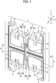
- FIG. 1 is a perspective view of detecting element in a preferred embodiment of the present invention of an angular rate sensor as one of the inertial force sensors.
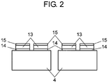
- FIG. 2 is an A-A sectional view in FIG. 1 .
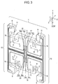
- FIG. 3 is a motion state diagram of the detecting element.
- the angular rate sensor has detecting element 1 composed of an elastic element for detecting an angular rate.
- this detecting element 1 has first arm 2 and second arm 4 formed orthogonally by coupling in orthogonal directions. It further includes support part 6 for coupling and supporting two first arms 2 and four second arms 4. Further, it includes third arm 10 vertically connected to first arm 2, and having its end part fixed to a mounting board (not shown). First arms 2 and third arm 10 are collectively called fixing arm 8. At this time, two first arms 2 and support part 6 are arranged nearly on a same straight line.
- fixing parts 9 may be mutually coupled
- third arm 10 may be formed in a square frame shape.
- Second arm 4 is provided with confronting part 16 bent at 180 degrees, and its leading end is coupled to weight 11. This weight 11 has recess 12.
- the side of support part 6 of mutually facing two second arms 4 is provided with first driving part 17 and second driving part 18 for driving and vibrating weight 11, and the side of support part 6 of other mutually facing two second arms 4 is provided with first sensing part 19 and second sensing part 20 for sensing the strain of second arms 4.
- First driving part 17 and second driving part 18 are electrode parts for driving weight 11 of two second arms 4, and first and second driving electrode parts 17a, 17b are disposed oppositely to one second arm 4, and third and fourth driving electrode parts 18a, 18b are disposed oppositely to other second arm 4.
- These first to fourth driving electrode parts 17a, 17b, 18a, 18b are, as shown in FIG. 2 , composed of lower electrode 14 and upper electrode 15 with intervening piezoelectric element 13.
- First sensing part 19 and second sensing part 20 are electrode parts for sensing the strain of two second arms 4, and first and second sensing electrode parts 19a, 19b are disposed oppositely to one second arm 4, and third and fourth sensing electrode parts 20a, 20b are disposed oppositely to other second arm 4.
- These first to fourth sensing electrode parts 19a, 19b, 20a, 20b, like first to fourth driving electrode parts 17a, 17b, 18a, 18b, are, as shown in FIG. 2 , composed of lower electrode 14 and upper electrode 15 with intervening piezoelectric element 13.
- lower electrode 14 composed of Pt is formed on second arms 4 made of silicon board by high frequency sputtering, and in the upper part of lower electrode 14, piezoelectric element 13 composed of PZT is formed by high frequency sputtering, and in the upper part of piezoelectric element 13 made of PZT, upper electrode 15 made of Au is formed by vapor deposition.
- FIG. 3 is a motion state diagram of this detecting element 1.
- first arm 2 of detecting element 1 is disposed in the X-axis direction
- second arm 4 is disposed in the Y-axis direction
- first to fourth driving electrode parts 17a, 17b, 18a, 18b second arm 4 is driven and vibrated starting from second arm 4 on which first driving part 17 and second driving part 18 are disposed, and at the same time, also, weight 11 is driven and vibrated in the opposite directions of second arm 4 (direction D indicated by solid line arrow and broken line arrow).
- the driving and vibrating direction in detecting element 1 is the X-axis direction.
- the resonance timing in direction D in FIG. 3 by driving and vibration is deflected in the direction of solid line in all drawings in all four second arms on a certain moment, and is deflected in the direction of broken line in all drawings in all four second arms on other moment.
- the Coriolis direction of detecting element 1 is the Y-axis direction.
- first sensing electrode part 19a and third sensing electrode part 20a sense contraction of second arms 4
- second sensing electrode part 19b and fourth sensing electrode part 20b sense expansion of second arms 4.
- first to fourth sensing electrode parts 19a, 19b, 20a, 20b Depending on the sensed expansion or contraction, an electric charge is generated in first to fourth sensing electrode parts 19a, 19b, 20a, 20b, and a current flows, and the angular rate is detected on the basis of this output current.
- strain occurring in the event of angular rate about the Z-axis or Y-axis occurs similarly on second arms 4 having first to fourth driving electrode parts 17a, 17b, 18a, 18b, and therefore first to fourth sensing electrode parts 19a, 19b, 20a, 20b may be disposed similarly on second arms 4 having first to fourth driving electrode parts 17a, 17b, 18a, 18b.
- first to fourth sensing electrode parts 19a, 19b, 20a, 20b The sensing operation of first to fourth sensing electrode parts 19a, 19b, 20a, 20b is specifically explained below.
- FIG. 4 is a circuit block diagram detecting circuit parts showing driving process and angular rate detecting process of angular rate sensor in the preferred embodiment of the present invention.
- a driving voltage is applied from driving process circuit 30 into first driving part 17 and second driving part 18.
- first to fourth driving electrode parts 17a, 17b, 18a, 18b, and first to fourth sensing electrode parts 19a, 19b, 20a, 20b the polarity of upper electrode 15 and lower electrode 14 in ordinary state free from angular rate is indicated within the broken line surrounding Pd.
- the polarity of upper electrode 15 and lower electrode 14 in the event of occurrence of angular rate is indicated within the broken line surrounding Pc.
- the polarity of lower electrode 14 is symmetrical to the polarity of upper electrode 15.
- first and second sensing electrode parts 19a, 19b of first sensing part 19, and third and fourth sensing electrode parts 20a, 20b of second sensing part 20 are processed as follows.
- the resonance timing in direction D in FIG. 3 by driving and vibration is deflected in the direction of solid line in all drawings in all four second arms on a certain moment, and is deflected in the direction of broken line in all drawings in all four second arms on other moment, but it is also applicable in other driving and vibration. That is, the resonance timing in direction D in FIG. 3 by driving and vibration is deflected in the direction of solid line in all drawings in upper two second arms and in the direction of broken line in lower two second arms on a certain moment, and is deflected in the direction of broken line in all drawings in upper two second arms and in the direction of solid line in lower two second arms on other moment, and in such resonance timing, too, it is possible to sense at high precision same as in the preferred embodiment.
- FIG. 5 is a circuit configuration example in which the reference voltage of the differential amplifier for determining the voltage output value is grounded, that is, zero volt.
- FIG. 6 is a circuit configuration example in which the reference voltage of the differential amplifier for determining the voltage output value is a certain reference voltage.
- FIG. 7 is an example of combination of the actual amplifier for obtaining a certain reference voltage shown in FIG. 6 and a resistance.
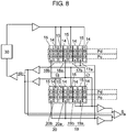
- FIG. 8 is other circuit diagram of detecting circuit part of driving process and angular rate detecting process of the angular rate sensor.
- a driving voltage is applied from driving process circuit 30 into first driving part 17 and second driving part 18.
- first to fourth driving electrode parts 17a, 17b, 18a, 18b, and first to fourth sensing electrode parts 19a, 19b, 20a, 20b the polarity of upper electrode 15 and lower electrode 14 in ordinary state free from angular rate is indicated within the broken line surrounding Pd.
- the polarity of upper electrode 15 and lower electrode 14 in the event of occurrence of angular rate is indicated within the broken line surrounding Pc.
- first and second sensing electrode parts 19a, 19b of first sensing part 19, and third and fourth sensing electrode parts 20a, 20b of second sensing part 20 are processed as follows.
- FIG. 8 shows an example of current adding circuit for operating other additions other than (5).
- the angular rate applied to detecting element 1 composed of an elastic element is detected, and if the current values issued from first to fourth sensing electrode parts 19a, 19b, 20a, 20b are very feeble, the detection sensitivity can be enhanced.
- the inertial force sensor of the present invention is capable of enhancing the detection sensitivity if the current flowing out from the sensing electrode part is very feeble, and is hence applicable in various electronic appliances.
Landscapes
- Physics & Mathematics (AREA)
- Engineering & Computer Science (AREA)
- General Physics & Mathematics (AREA)
- Radar, Positioning & Navigation (AREA)
- Remote Sensing (AREA)
- Gyroscopes (AREA)
Description
- The present invention relates to an inertial force sensor for detecting the inertial force used in various electronic appliances for position control or navigation of mobile structures such as aircraft, automobile, robot, vessel and vehicle.
- A conventional inertial force sensor is explained below. The inertial force sensor includes an angular rate sensor and an acceleration sensor. Generally, the angular rate sensor has a detecting element in various shapes, such as tuning fork shape, H-shape, T-shape and others, and by vibrating the detecting element, the strain of the detecting element accompanied by generation of Coriolis force is sensed electrically, and the angular rate is detected. The acceleration sensor has a detecting element having a weight, and the strain of the detecting element due to move of the weight is sensed electrically, and the acceleration is detected. To sense the strain, for example, a sensing electrode part consisting of upper electrode and lower electrode with an intervening piezoelectric element is disposed in the detecting element, and the angular rate or acceleration is detected on the basis of the current flowing out from the sensing electrode part accompanied by strain of the detecting element.
- A plurality of inertial force sensors such as angular rate sensors or acceleration sensors are used in the position control device or navigation device of mobile structure such as vehicle, being disposed corresponding to the inertial force to be detected or the axis of detection. A prior art relating to the present invention is disclosed, for example, in
patent document 1. In the conventional inertial force sensor, the strain of the detecting element is very slight when detecting the angular rate or acceleration on the basis of the current flowing out from the sensing electrode part, and the output current from the sensing detecting part is also very small, and the detection sensitivity is low. - Patent document 1: Unexamined Japanese Patent Application Publication No.
2005-249395 -
EP1696205 discloses a tuning-fork type transducer for an angular-speed sensor which realizes a stable fork-driving, realizes downsizing of the angular-speed sensor, and is capable of executing control of a vehicle body with high degree of accuracy when being used under a high-temperature environment, an angular-speed sensor using this transducer, and an automotive vehicle using this angular-speed sensor. Electric charges obtained from upper electrodes provided on one or two arms are amplified respectively by current amplifiers. The amplified signal is differentially amplified by a first differential amplifier, and the amplified signal is used as a monitor signal for fork-driving. An added signal obtained by adding output signals from the current amplifiers by an adder is used as a signal for detecting the angular speed. -
JP10170279 - The present invention provides an inertial force sensor according to
claim 1. In addition, optional features of the present invention are set out in the dependent claims. The present invention presents an inertial force sensor enhanced in the detection sensitivity. -
-
FIG. 1 is a perspective view of detecting element of angular rate sensor in a preferred embodiment of the present invention. -
FIG. 2 is an A-A sectional view inFIG. 1 . -
FIG. 3 is a motion state diagram of detecting element of angular rate sensor in the preferred embodiment of the present invention. -
FIG. 4 is a circuit block diagram showing driving process and angular rate detecting process of angular rate sensor in the preferred embodiment of the present invention. -
FIG. 5 is a circuit block diagram of angular rate detecting process of angular rate sensor in the preferred embodiment of the present invention. -
FIG. 6 is a circuit block diagram of angular rate detecting process of angular rate sensor in the preferred embodiment of the present invention. -
FIG. 7 is a circuit block diagram of angular rate detecting process of angular rate sensor in the preferred embodiment of the present invention. -
FIG. 8 is a circuit block diagram showing driving process and angular rate detecting process of angular rate sensor in other preferred embodiment of the present invention. -
- 1
- Detecting element
- 2
- First arm
- 4
- Second arm
- 6
- Support part
- 8
- Fixing arm
- 10
- Third arm
- 11
- Weight
- 12
- Recess
- 13
- Piezoelectric element
- 14
- Lower electrode
- 15
- Upper electrode
- 17
- First driving part
- 17a
- First driving electrode part
- 17b
- Second driving electrode part
- 18
- Second driving part
- 18a
- Third driving electrode part
- 18b
- Fourth driving electrode part
- 19
- First sensing part
- 19a
- First sensing electrode part
- 19b
- Second sensing electrode part
- 20
- Second sensing part
- 20a
- Third sensing electrode part
- 20b
- Fourth sensing electrode part
-
FIG. 1 is a perspective view of detecting element in a preferred embodiment of the present invention of an angular rate sensor as one of the inertial force sensors.FIG. 2 is an A-A sectional view inFIG. 1 .FIG. 3 is a motion state diagram of the detecting element. The angular rate sensor has detectingelement 1 composed of an elastic element for detecting an angular rate. InFIG. 1 , this detectingelement 1 hasfirst arm 2 andsecond arm 4 formed orthogonally by coupling in orthogonal directions. It further includessupport part 6 for coupling and supporting twofirst arms 2 and foursecond arms 4. Further, it includesthird arm 10 vertically connected tofirst arm 2, and having its end part fixed to a mounting board (not shown).First arms 2 andthird arm 10 are collectively called fixingarm 8. At this time, twofirst arms 2 and supportpart 6 are arranged nearly on a same straight line. As a variation of the shape, fixingparts 9 may be mutually coupled, andthird arm 10 may be formed in a square frame shape. -
Second arm 4 is provided with confrontingpart 16 bent at 180 degrees, and its leading end is coupled toweight 11. Thisweight 11 hasrecess 12. - Of the four
second arms 4, the side ofsupport part 6 of mutually facing twosecond arms 4 is provided with first drivingpart 17 and second drivingpart 18 for driving and vibratingweight 11, and the side ofsupport part 6 of other mutually facing twosecond arms 4 is provided withfirst sensing part 19 andsecond sensing part 20 for sensing the strain ofsecond arms 4. - First driving
part 17 and second drivingpart 18 are electrode parts for drivingweight 11 of twosecond arms 4, and first and second drivingelectrode parts second arm 4, and third and fourth drivingelectrode parts second arm 4. These first to fourth drivingelectrode parts FIG. 2 , composed oflower electrode 14 andupper electrode 15 with interveningpiezoelectric element 13. - First sensing
part 19 andsecond sensing part 20 are electrode parts for sensing the strain of twosecond arms 4, and first and secondsensing electrode parts second arm 4, and third and fourthsensing electrode parts second arm 4. These first to fourthsensing electrode parts electrode parts FIG. 2 , composed oflower electrode 14 andupper electrode 15 with interveningpiezoelectric element 13. - As shown in
FIG. 2 , in first to fourth drivingelectrode parts sensing electrode parts lower electrode 14 composed of Pt is formed onsecond arms 4 made of silicon board by high frequency sputtering, and in the upper part oflower electrode 14,piezoelectric element 13 composed of PZT is formed by high frequency sputtering, and in the upper part ofpiezoelectric element 13 made of PZT,upper electrode 15 made of Au is formed by vapor deposition. -
FIG. 3 is a motion state diagram of this detectingelement 1. On the X-axis, Y-axis, and Z-axis mutually crossed orthogonally, whenfirst arm 2 of detectingelement 1 is disposed in the X-axis direction, andsecond arm 4 is disposed in the Y-axis direction, if alternating-current voltage of resonance frequency is applied to first to fourth drivingelectrode parts second arm 4 is driven and vibrated starting fromsecond arm 4 on which first drivingpart 17 and second drivingpart 18 are disposed, and at the same time, also,weight 11 is driven and vibrated in the opposite directions of second arm 4 (direction D indicated by solid line arrow and broken line arrow). Foursecond arms 4 and fourweights 11 are all united, and driven and vibrated in the opposite directions ofsecond arms 4. The driving and vibrating direction in detectingelement 1 is the X-axis direction. In this preferred embodiment, the resonance timing in direction D inFIG. 3 by driving and vibration is deflected in the direction of solid line in all drawings in all four second arms on a certain moment, and is deflected in the direction of broken line in all drawings in all four second arms on other moment. - If an angular rate takes place at this time, for example, counterclockwise (CCW) about the Z-axis, in tune with the driving and vibration of
weight 11, a Coriolis force is generated in a direction (direction C indicated by solid line arrow) orthogonal to the driving and vibrating direction toweight 11, and therefore a strain due to the angular rate in the counterclockwise direction of the Z-axis can be generate insecond arm 4. The Coriolis direction of detectingelement 1 is the Y-axis direction. - At this time, for example, when an angular rate occurs in the Coriolis direction (C-direction) indicated by solid line arrow, in
second arms 4 having first to fourthsensing electrode parts sensing electrode part 19a and thirdsensing electrode part 20a sense contraction ofsecond arms 4, and secondsensing electrode part 19b and fourthsensing electrode part 20b sense expansion ofsecond arms 4. When Coriolis force is generated in the Coriolis direction indicated by broken line arrow, expansion or contraction is sensed in the reverse direction. - Depending on the sensed expansion or contraction, an electric charge is generated in first to fourth
sensing electrode parts - On the other hand, when angular rate occurs clockwise (CW) on the Z-axis, opposite to the case of the angular rate occurring counterclockwise (CCW) on the Z-axis,
second arms 4 expand and contract, and this expansion or contraction is sensed by first to fourthsensing electrode parts - When an angular rate occurs about the Y-axis, in tune with the driving and vibration of
weight 11, a Coriolis force occurs in the direction (Z-axis direction) orthogonal to the driving and vibrating direction toweight 11, and a strain due to angular rate about the Y-axis is generated insecond arms 4, and expansion or contraction ofsecond arms 4 can be sensed by first to fourthsensing electrode parts - The strain occurring in the event of angular rate about the Z-axis or Y-axis occurs similarly on
second arms 4 having first to fourth drivingelectrode parts sensing electrode parts second arms 4 having first to fourth drivingelectrode parts - The sensing operation of first to fourth
sensing electrode parts -
FIG. 4 is a circuit block diagram detecting circuit parts showing driving process and angular rate detecting process of angular rate sensor in the preferred embodiment of the present invention. InFIG. 4 , a driving voltage is applied from drivingprocess circuit 30 into first drivingpart 17 and second drivingpart 18. In first to fourth drivingelectrode parts sensing electrode parts upper electrode 15 andlower electrode 14 in ordinary state free from angular rate is indicated within the broken line surrounding Pd. The polarity ofupper electrode 15 andlower electrode 14 in the event of occurrence of angular rate is indicated within the broken line surrounding Pc. The polarity oflower electrode 14 is symmetrical to the polarity ofupper electrode 15. In such polarity relation, depending on the alternating-current signal entered in first to fourth drivingelectrode parts upper electrode 15 andlower electrode 14 is inverted alternately, and the angular rate is detected by the detecting circuit part. - When detecting the angular rate in the event of occurrence of angular rate, the outputs from first and second
sensing electrode parts first sensing part 19, and third and fourthsensing electrode parts second sensing part 20 are processed as follows. - (1) Output values issued from
upper electrode 15 of secondsensing electrode part 19b andupper electrode 15 of fourthsensing electrode part 20b both in positive polarity are added, and a first sum is obtained. - (2) Output values issued from
upper electrode 15 of firstsensing electrode part 19a andupper electrode 15 of thirdsensing electrode part 20a both in negative polarity are added, and a second sum is obtained. - (3) Output values issued from
lower electrode 14 of firstsensing electrode part 19a andlower electrode 14 of thirdsensing electrode part 20a both in positive polarity are added, and a third sum is obtained.FIG. 4 shows an example of current adding circuit. - (4) Output values issued from
lower electrode 14 of secondsensing electrode part 19b andlower electrode 14 of fourthsensing electrode part 20b both in negative polarity are added, and a fourth sum is obtained.FIG. 4 shows an example of current adding circuit. - (5) Differential amplification value S1 of first sum and second sum, and differential amplification value S2 of third sum and fourth sum are detected.
- (6) The third sum is summed up with output values issued from
lower electrode 14 of seconddriving electrode part 17b of first drivingpart 17 andlower electrode 14 of seconddriving electrode part 18b of second drivingpart 18.FIG. 4 shows an example of current adding circuit. - (7) The fourth sum is summed up with output values issued from
lower electrode 14 of firstdriving electrode part 17a of first drivingpart 17 andlower electrode 14 of thirddriving electrode part 18a.FIG. 4 shows an example of current adding circuit. - In further processing, due to expansion and contraction of
second arms 4, the polarity is alternately changed to positive and negative, and when the polarity is opposite, the outputs are processed as follows. - (1) Output values issued from
upper electrode 15 of firstsensing electrode part 19a andupper electrode 15 of thirdsensing electrode part 20a both in positive polarity are added, and a first sum is obtained. - (2) Output values issued from
upper electrode 15 of secondsensing electrode part 19b andupper electrode 15 of fourthsensing electrode part 20b both in negative polarity are added, and a second sum is obtained. - (3) Output values issued from
lower electrode 14 of secondsensing electrode part 19b andlower electrode 14 of fourthsensing electrode part 20b both in positive polarity are added, and a third sum is obtained. - (4) Output values issued from
lower electrode 14 of firstsensing electrode part 19a andlower electrode 14 of thirdsensing electrode part 20a both in negative polarity are added, and a fourth sum is obtained. - (5) Differential amplification value of first sum and second sum, and differential amplification value of third sum and fourth sum are detected.
- (6) The third sum is summed up with output values issued from
lower electrode 14 of firstdriving electrode part 17a of first drivingpart 17 andlower electrode 14 of thirddriving electrode part 18a. - (7) The fourth sum is summed up with output values issued from
lower electrode 14 of seconddriving electrode part 17b of first drivingpart 17 andlower electrode 14 of seconddriving electrode part 18b of second drivingpart 18. - In the preferred embodiment, the resonance timing in direction D in
FIG. 3 by driving and vibration is deflected in the direction of solid line in all drawings in all four second arms on a certain moment, and is deflected in the direction of broken line in all drawings in all four second arms on other moment, but it is also applicable in other driving and vibration. That is, the resonance timing in direction D inFIG. 3 by driving and vibration is deflected in the direction of solid line in all drawings in upper two second arms and in the direction of broken line in lower two second arms on a certain moment, and is deflected in the direction of broken line in all drawings in upper two second arms and in the direction of solid line in lower two second arms on other moment, and in such resonance timing, too, it is possible to sense at high precision same as in the preferred embodiment. - Detection of angular rate in this configuration is shown in
FIG. 5 to FIG. 7 , in which on the basis of both output values issued fromlower electrode 14 andupper electrode 15 formed together with interveningpiezoelectric element 13, signal S can be detected as voltage.FIG. 5 is a circuit configuration example in which the reference voltage of the differential amplifier for determining the voltage output value is grounded, that is, zero volt.FIG. 6 is a circuit configuration example in which the reference voltage of the differential amplifier for determining the voltage output value is a certain reference voltage.FIG. 7 is an example of combination of the actual amplifier for obtaining a certain reference voltage shown inFIG. 6 and a resistance. -
FIG. 8 is other circuit diagram of detecting circuit part of driving process and angular rate detecting process of the angular rate sensor. InFIG. 8 , a driving voltage is applied from drivingprocess circuit 30 into first drivingpart 17 and second drivingpart 18. In first to fourth drivingelectrode parts sensing electrode parts upper electrode 15 andlower electrode 14 in ordinary state free from angular rate is indicated within the broken line surrounding Pd. The polarity ofupper electrode 15 andlower electrode 14 in the event of occurrence of angular rate is indicated within the broken line surrounding Pc. In such polarity relation, depending on the alternating-current signal entered in first to fourth drivingelectrode parts upper electrode 15 andlower electrode 14 is inverted alternately, and the angular rate is detected by the detecting circuit part. - When detecting the angular rate in the event of occurrence of angular rate, the outputs from first and second
sensing electrode parts first sensing part 19, and third and fourthsensing electrode parts second sensing part 20 are processed as follows. - (1) Output values issued from
upper electrode 15 of secondsensing electrode part 19b andlower electrode 14 of firstsensing electrode part 19a both in positive polarity offirst sensing part 19 are added, and a first sum is obtained. - (2) Output values issued from
upper electrode 15 of firstsensing electrode part 19a andlower electrode 14 of secondsensing electrode part 19b both in negative polarity offirst sensing part 19 are added, and a second sum is obtained. - (3) Output values issued from
upper electrode 15 of fourthsensing electrode part 20b andlower electrode 14 of thirdsensing electrode part 20a both in positive polarity ofsecond sensing part 20 are added, and a third sum is obtained. - (4) Output values issued from
upper electrode 15 of thirdsensing electrode part 20a andlower electrode 14 of fourthsensing electrode part 20b both in negative polarity ofsecond sensing part 20 are added, and a fourth sum is obtained. - (5) Differential amplification value of sum of the first sum and third sum, and the sum of the second sum and fourth sum is detected.
- (6) The third sum is summed up with output values issued from
upper electrode 15 of firstdriving electrode part 17a of first drivingpart 17 andlower electrode 14 of seconddriving electrode part 17b of first drivingpart 17. - (7) The second sum is summed up with output values issued from
lower electrode 14 of thirddriving electrode part 18a of second drivingpart 18 andupper electrode 15 of fourthdriving electrode part 18b. -
FIG. 8 shows an example of current adding circuit for operating other additions other than (5). - In further processing, due to expansion and contraction of
second arms 4, the polarity is alternately changed to positive and negative, and when the polarity is opposite, the outputs are processed as follows. - (1) Output values issued from
upper electrode 15 of firstsensing electrode part 19a andlower electrode 14 of secondsensing electrode part 19b both in positive polarity offirst sensing part 19 are added, and a first sum is obtained. - (2) Output values issued from
upper electrode 15 of secondsensing electrode part 19b andlower electrode 14 of firstsensing electrode part 19a both in negative polarity offirst sensing part 19 are added, and a second sum is obtained. - (3) Output values issued from
upper electrode 15 of thirdsensing electrode part 20a andlower electrode 14 of fourthsensing electrode part 20b both in positive polarity ofsecond sensing part 20 are added, and a third sum is obtained. - (4) Output values issued from
upper electrode 15 of fourthsensing electrode part 20b andlower electrode 14 of thirdsensing electrode part 20a both in negative polarity ofsecond sensing part 20 are added, and a fourth sum is obtained. - (5) Differential amplification value of sum of the first sum and second sum, and the sum of the second sum and fourth sum is detected.
- (6) The fourth sum is summed up with output values issued from
upper electrode 15 of firstdriving electrode part 17a of first drivingpart 17 andlower electrode 14 of seconddriving electrode part 17b of first drivingpart 17. - (7) The first sum is summed up with output values issued from
lower electrode 14 of thirddriving electrode part 18a of second drivingpart 18 andupper electrode 15 of fourthdriving electrode part 18b. - In this configuration, detection of angular rate is detected, shown in
FIG. 5 to FIG. 7 , on the basis of both output values issued fromlower electrode 14 andupper electrode 15 formed together with interveningpiezoelectric element 13. - In this configuration, on the basis of the output values issued from
upper electrode 15 of first to fourthsensing electrode parts lower electrode 14 of first to fourthsensing electrode parts element 1 composed of an elastic element is detected, and if the current values issued from first to fourthsensing electrode parts - As for the sum values, between outputs both in positive polarity, the two outputs are directly connected and entered into the amplifier, and an output of double current value is obtained. Between outputs both in negative polarity, the two outputs are directly, and the output value is doubled. Therefore, when the current direction is the same, the output is doubled by a simple wiring. Such output doubling method may be realized also by not direct wiring method. In the case of the output from positive polarity and the output from negative polarity, only absolute values of the outputs can be added easily by modifying the later circuit.
- In the foregoing explanation, the plus and minus sign of the output corresponding to the entered inertial force and the method of doubling the output are mentioned, but unnecessary signal components may be superimposed on the output, and in such a case the unnecessary signal components can be canceled by adding an output reverse in the polarity of the unnecessary signal components and nearly same in the absolute value. When the polarity of unnecessary signal components is the same, they can be similarly canceled by subtracting.
- The inertial force sensor of the present invention is capable of enhancing the detection sensitivity if the current flowing out from the sensing electrode part is very feeble, and is hence applicable in various electronic appliances.
Claims (5)
- An inertial force sensor comprising:a detecting element (1) composed of an elastic element, the detecting element (1) comprising a first sensing part (19) and a second sensing part (20) both disposed on the elastic element for sensing the strain of the elastic element, wherein the elastic element has a plurality of second arms (4), one second arm provided with the first sensing part (19) and another second arm (4) with the second sensing part (20), anddetecting circuit parts connected to the first sensing part (19) and the second sensing part (20) for detecting the inertial force applied to the elastic element, whereinthe first sensing part (19) has first and second sensing electrode parts (19a, 19b), and the second sensing part (20) has third and fourth sensing electrode parts (20a, 20b), each of the first, second, third and fourth sensing electrode part is composed of an upper electrode (15) and a lower electrode (14) together with an intervening piezoelectric element (13), and characterized in thatthe detecting circuit part is adapted to detect the inertial force applied to the elastic element on the basis of a first sum, a second sum, a third sum and a fourth sum which are the sums of output values issued from the upper electrodes (15) and output values issued from the lower electrodes (14),wherein in a first case for the inertial force sensor,the first sum is a value obtained by adding output values issued from the upper electrode (15) of the second sensing electrode part (19b) and the upper electrode (15) of the fourth sensing electrode part (20b) both in positive polarity,the second sum is a value obtained by adding output values issued from the upper electrode 15 of the first sensing electrode part (19a) and the upper electrode (15) of the third sensing electrode part (20a) both in negative polarity,the third sum is a value obtained by adding output values issued from the lower electrode (14) of the first sensing electrode part (19a) and the lower electrode (14) of the third sensing electrode part (20a) both in positive polarity, andthe fourth sum is a value obtained by adding output values issued from the lower electrode (14) of the second sensing electrode part (19b) and the lower electrode (14) of the fourth sensing electrode part (20b) both in negative polarity, andwherein in a second case for the inertial force sensor,the first sum is a value obtained by adding output values issued from the upper electrode (15) of the second sensing electrode part (19b) and the lower electrode (14) of the first sensing electrode part (19a) both in positive polarity of the first sensing part,the second sum is a value obtained by adding output values issued from the upper electrode (15) of the first sensing electrode part (19a) and the lower electrode (14) of the second sensing electrode part (19b) both in negative polarity of the first sensing part,the third sum is a value obtained by adding output values issued from the upper electrode (15) of the fourth sensing electrode part (20b) and the lower electrode (14) of the third sensing electrode part (20a) both in positive polarity of the second sensing part, andthe fourth sum is a value obtained by adding output values issued from the upper electrode (15) of the third sensing electrode part (20a) and the lower electrode (14) of the fourth sensing electrode part (20b) both in negative polarity of the second sensing part.
- The inertial force sensor of claim 1, further comprising:a driving part (17, 18) disposed on the elastic element for driving and vibrating the elastic element.
- The inertial force sensor of claim 2, wherein the sums are obtained by addition of output currents issued from the upper electrode or lower electrode of the sensing electrode parts both in positive polarity or both in negative polarity, or from the upper electrode or lower electrode of the driving electrode part.
- The inertial force sensor of claim 1, wherein the second arms are arranged in two parallel rows.
- The inertial force sensor of claim 2, wherein the second arms are arranged in two parallel rows on the elastic element, a common support part is provided in the second arms, and relating to the support part of one second arm and other second arm, other second arm is disposed at the opposite side, and further the driving part is provided in other second arm.
Applications Claiming Priority (2)
| Application Number | Priority Date | Filing Date | Title |
|---|---|---|---|
| JP2006256654A JP2008076265A (en) | 2006-09-22 | 2006-09-22 | Inertial force sensor |
| PCT/JP2007/068035 WO2008035649A1 (en) | 2006-09-22 | 2007-09-18 | Inertia force sensor |
Publications (3)
| Publication Number | Publication Date |
|---|---|
| EP2037217A1 EP2037217A1 (en) | 2009-03-18 |
| EP2037217A4 EP2037217A4 (en) | 2013-01-02 |
| EP2037217B1 true EP2037217B1 (en) | 2018-03-07 |
Family
ID=39200475
Family Applications (1)
| Application Number | Title | Priority Date | Filing Date |
|---|---|---|---|
| EP07828236.5A Active EP2037217B1 (en) | 2006-09-22 | 2007-09-18 | Inertia force sensor |
Country Status (5)
| Country | Link |
|---|---|
| US (1) | US8074517B2 (en) |
| EP (1) | EP2037217B1 (en) |
| JP (1) | JP2008076265A (en) |
| CN (1) | CN101501448B (en) |
| WO (1) | WO2008035649A1 (en) |
Families Citing this family (8)
| Publication number | Priority date | Publication date | Assignee | Title |
|---|---|---|---|---|
| EP2056069A1 (en) * | 2006-09-21 | 2009-05-06 | Panasonic Corporation | Angular velocity sensor |
| EP2053413B1 (en) * | 2006-11-14 | 2013-05-22 | Panasonic Corporation | Sensor |
| US8117914B2 (en) * | 2007-02-20 | 2012-02-21 | Panasonic Corporation | Inertia force sensor and composite sensor for detecting inertia force |
| WO2010073576A1 (en) * | 2008-12-26 | 2010-07-01 | パナソニック株式会社 | Angular velocity sensor |
| JP5906394B2 (en) * | 2010-06-25 | 2016-04-20 | パナソニックIpマネジメント株式会社 | Inertial force detection element and inertial force sensor using the same |
| WO2012090452A1 (en) * | 2010-12-28 | 2012-07-05 | パナソニック株式会社 | Angular velocity sensor |
| JP5942097B2 (en) * | 2011-10-24 | 2016-06-29 | パナソニックIpマネジメント株式会社 | Angular velocity sensor and detection element used therefor |
| CN113631882B (en) * | 2019-03-29 | 2023-12-12 | 松下知识产权经营株式会社 | Angular velocity sensor |
Citations (1)
| Publication number | Priority date | Publication date | Assignee | Title |
|---|---|---|---|---|
| JPH1114373A (en) * | 1997-06-27 | 1999-01-22 | Ngk Insulators Ltd | Vibration gyroscope |
Family Cites Families (14)
| Publication number | Priority date | Publication date | Assignee | Title |
|---|---|---|---|---|
| US4654663A (en) * | 1981-11-16 | 1987-03-31 | Piezoelectric Technology Investors, Ltd. | Angular rate sensor system |
| JPH0894362A (en) * | 1994-09-20 | 1996-04-12 | Yoshiro Tomikawa | Oscillatory gyroscope |
| JP3549590B2 (en) * | 1994-09-28 | 2004-08-04 | 和廣 岡田 | Acceleration / angular velocity sensor |
| JP3671570B2 (en) * | 1996-12-10 | 2005-07-13 | 株式会社村田製作所 | Vibrating gyro |
| JP4004129B2 (en) * | 1998-02-09 | 2007-11-07 | マイクロストーン株式会社 | Motion sensor |
| JP3684873B2 (en) | 1998-10-29 | 2005-08-17 | ソニー株式会社 | Angular velocity sensor |
| JP3972790B2 (en) * | 2001-11-27 | 2007-09-05 | 松下電器産業株式会社 | Thin film micromechanical resonator and thin film micromechanical resonator gyro |
| JP3829861B2 (en) * | 2002-08-07 | 2006-10-04 | 松下電器産業株式会社 | Angular velocity sensor |
| JP4356479B2 (en) | 2004-03-01 | 2009-11-04 | パナソニック株式会社 | Angular velocity sensor |
| JP2005249646A (en) * | 2004-03-05 | 2005-09-15 | Matsushita Electric Ind Co Ltd | Tuning fork type oscillator for angular velocity sensor, angular velocity sensor using the oscillator, and automobile using the angular velocity sensor |
| JP4134136B2 (en) * | 2005-10-04 | 2008-08-13 | 和廣 岡田 | Angular velocity sensor |
| EP2063224A4 (en) * | 2006-08-21 | 2012-05-09 | Panasonic Corp | Angular velocity sensor |
| US20100126270A1 (en) * | 2007-04-13 | 2010-05-27 | Panasonic Corporation | Inertia force sensor |
| JP5319122B2 (en) * | 2008-01-21 | 2013-10-16 | 日立オートモティブシステムズ株式会社 | Inertial sensor |
-
2006
- 2006-09-22 JP JP2006256654A patent/JP2008076265A/en active Pending
-
2007
- 2007-09-18 EP EP07828236.5A patent/EP2037217B1/en active Active
- 2007-09-18 CN CN2007800299280A patent/CN101501448B/en not_active Expired - Fee Related
- 2007-09-18 WO PCT/JP2007/068035 patent/WO2008035649A1/en active Application Filing
- 2007-09-18 US US12/376,985 patent/US8074517B2/en active Active
Patent Citations (1)
| Publication number | Priority date | Publication date | Assignee | Title |
|---|---|---|---|---|
| JPH1114373A (en) * | 1997-06-27 | 1999-01-22 | Ngk Insulators Ltd | Vibration gyroscope |
Non-Patent Citations (1)
| Title |
|---|
| JAYANT SIROHI ET AL: "Fundamental Understanding of Piezoelectric Strain Sensors", JOURNAL OF INTELLIGENT MATERIAL SYSTEMS AND STRUCTURES, vol. 11, no. 4, 1 April 2000 (2000-04-01), pages 246 - 257, XP055195276, ISSN: 1045-389X, DOI: 10.1106/8BFB-GC8P-XQ47-YCQ0 * |
Also Published As
| Publication number | Publication date |
|---|---|
| EP2037217A1 (en) | 2009-03-18 |
| US8074517B2 (en) | 2011-12-13 |
| CN101501448B (en) | 2013-01-02 |
| US20100199761A1 (en) | 2010-08-12 |
| EP2037217A4 (en) | 2013-01-02 |
| JP2008076265A (en) | 2008-04-03 |
| CN101501448A (en) | 2009-08-05 |
| WO2008035649A1 (en) | 2008-03-27 |
Similar Documents
| Publication | Publication Date | Title |
|---|---|---|
| EP2037217B1 (en) | Inertia force sensor | |
| EP2899502B1 (en) | Inertial force sensor | |
| JP5205725B2 (en) | Angular velocity sensor | |
| US6742390B2 (en) | Angular velocity sensor | |
| US8082790B2 (en) | Solid-state inertial sensor on chip | |
| EP0568978B1 (en) | Gyro-compass | |
| EP2063224A1 (en) | Angular velocity sensor | |
| JP2000206141A (en) | Momentum sensor | |
| JP2007256235A (en) | Inertia force sensor | |
| JPH08159806A (en) | Azimuth sensor aand azimuth/distance sensor | |
| JP4687085B2 (en) | Compound sensor | |
| JP2007256234A (en) | Inertia force sensor | |
| JP2001241952A (en) | Angular velocity sensor | |
| JP3136544B2 (en) | Gyro device | |
| JP2007198778A (en) | Inertial force sensor | |
| JP2007198779A (en) | Inertial force sensor | |
| JP2007178386A (en) | Compound sensor | |
| JP2008261771A (en) | Inertia force sensor | |
| KR19990026668A (en) | Semiconductor Angular Velocity Sensor | |
| JP2007198780A (en) | Inertial force sensor | |
| KR19990026669A (en) | Semiconductor Angular Velocity Sensor | |
| JP2008261772A (en) | Inertia force sensor |
Legal Events
| Date | Code | Title | Description |
|---|---|---|---|
| PUAI | Public reference made under article 153(3) epc to a published international application that has entered the european phase |
Free format text: ORIGINAL CODE: 0009012 |
|
| 17P | Request for examination filed |
Effective date: 20090115 |
|
| AK | Designated contracting states |
Kind code of ref document: A1 Designated state(s): AT BE BG CH CY CZ DE DK EE ES FI FR GB GR HU IE IS IT LI LT LU LV MC MT NL PL PT RO SE SI SK TR |
|
| AX | Request for extension of the european patent |
Extension state: AL BA HR MK RS |
|
| RBV | Designated contracting states (corrected) |
Designated state(s): DE |
|
| DAX | Request for extension of the european patent (deleted) | ||
| A4 | Supplementary search report drawn up and despatched |
Effective date: 20121203 |
|
| RIC1 | Information provided on ipc code assigned before grant |
Ipc: H01L 41/22 20130101ALI20121127BHEP Ipc: H01L 41/08 20060101ALI20121127BHEP Ipc: G01C 19/56 20120101AFI20121127BHEP |
|
| 17Q | First examination report despatched |
Effective date: 20141217 |
|
| RAP1 | Party data changed (applicant data changed or rights of an application transferred) |
Owner name: PANASONIC INTELLECTUAL PROPERTY MANAGEMENT CO., LT |
|
| RAP1 | Party data changed (applicant data changed or rights of an application transferred) |
Owner name: PANASONIC INTELLECTUAL PROPERTY MANAGEMENT CO., LT |
|
| RIC1 | Information provided on ipc code assigned before grant |
Ipc: G01C 19/56 20120101AFI20170906BHEP Ipc: H01L 41/08 20060101ALI20170906BHEP Ipc: H01L 41/113 20060101ALI20170906BHEP Ipc: G01C 19/5607 20120101ALI20170906BHEP |
|
| GRAP | Despatch of communication of intention to grant a patent |
Free format text: ORIGINAL CODE: EPIDOSNIGR1 |
|
| STAA | Information on the status of an ep patent application or granted ep patent |
Free format text: STATUS: GRANT OF PATENT IS INTENDED |
|
| INTG | Intention to grant announced |
Effective date: 20171208 |
|
| GRAS | Grant fee paid |
Free format text: ORIGINAL CODE: EPIDOSNIGR3 |
|
| GRAA | (expected) grant |
Free format text: ORIGINAL CODE: 0009210 |
|
| STAA | Information on the status of an ep patent application or granted ep patent |
Free format text: STATUS: THE PATENT HAS BEEN GRANTED |
|
| AK | Designated contracting states |
Kind code of ref document: B1 Designated state(s): DE |
|
| REG | Reference to a national code |
Ref country code: DE Ref legal event code: R096 Ref document number: 602007054173 Country of ref document: DE |
|
| REG | Reference to a national code |
Ref country code: DE Ref legal event code: R097 Ref document number: 602007054173 Country of ref document: DE |
|
| RIC2 | Information provided on ipc code assigned after grant |
Ipc: G01C 19/56 20120101AFI20170906BHEP Ipc: H01L 41/08 20060101ALI20170906BHEP Ipc: H01L 41/113 20060101ALI20170906BHEP Ipc: G01C 19/5607 20120101ALI20170906BHEP |
|
| PLBE | No opposition filed within time limit |
Free format text: ORIGINAL CODE: 0009261 |
|
| STAA | Information on the status of an ep patent application or granted ep patent |
Free format text: STATUS: NO OPPOSITION FILED WITHIN TIME LIMIT |
|
| 26N | No opposition filed |
Effective date: 20181210 |
|
| RIC2 | Information provided on ipc code assigned after grant |
Ipc: H01L 41/113 20060101ALI20170906BHEP Ipc: H01L 41/08 20060101ALI20170906BHEP Ipc: G01C 19/56 20120101AFI20170906BHEP Ipc: G01C 19/5607 20120101ALI20170906BHEP |
|
| PGFP | Annual fee paid to national office [announced via postgrant information from national office to epo] |
Ref country code: DE Payment date: 20240702 Year of fee payment: 18 |