EP2036840B1 - Vorrichtung zur Aufnahme und zum Transport eines Gutes - Google Patents
Vorrichtung zur Aufnahme und zum Transport eines Gutes Download PDFInfo
- Publication number
- EP2036840B1 EP2036840B1 EP20080015815 EP08015815A EP2036840B1 EP 2036840 B1 EP2036840 B1 EP 2036840B1 EP 20080015815 EP20080015815 EP 20080015815 EP 08015815 A EP08015815 A EP 08015815A EP 2036840 B1 EP2036840 B1 EP 2036840B1
- Authority
- EP
- European Patent Office
- Prior art keywords
- rollers
- article
- sliding unit
- frame structure
- driven
- Prior art date
- Legal status (The legal status is an assumption and is not a legal conclusion. Google has not performed a legal analysis and makes no representation as to the accuracy of the status listed.)
- Not-in-force
Links
- 235000013351 cheese Nutrition 0.000 description 2
- 238000011161 development Methods 0.000 description 2
- 230000018109 developmental process Effects 0.000 description 2
- 235000013372 meat Nutrition 0.000 description 2
- 230000002093 peripheral effect Effects 0.000 description 2
- 235000013580 sausages Nutrition 0.000 description 2
- 238000006073 displacement reaction Methods 0.000 description 1
- 235000013305 food Nutrition 0.000 description 1
- 239000000463 material Substances 0.000 description 1
- 238000004806 packaging method and process Methods 0.000 description 1
- 239000004065 semiconductor Substances 0.000 description 1
- 235000012431 wafers Nutrition 0.000 description 1
Images


Classifications
-
- B—PERFORMING OPERATIONS; TRANSPORTING
- B65—CONVEYING; PACKING; STORING; HANDLING THIN OR FILAMENTARY MATERIAL
- B65G—TRANSPORT OR STORAGE DEVICES, e.g. CONVEYORS FOR LOADING OR TIPPING, SHOP CONVEYOR SYSTEMS OR PNEUMATIC TUBE CONVEYORS
- B65G47/00—Article or material-handling devices associated with conveyors; Methods employing such devices
- B65G47/74—Feeding, transfer, or discharging devices of particular kinds or types
- B65G47/90—Devices for picking-up and depositing articles or materials
-
- B—PERFORMING OPERATIONS; TRANSPORTING
- B25—HAND TOOLS; PORTABLE POWER-DRIVEN TOOLS; MANIPULATORS
- B25J—MANIPULATORS; CHAMBERS PROVIDED WITH MANIPULATION DEVICES
- B25J11/00—Manipulators not otherwise provided for
- B25J11/0045—Manipulators used in the food industry
Definitions
- the invention relates to a device for receiving and transporting a good having receiving means, which are pushed by a sliding device under the estate.
- the receiving means after they have picked up the goods from a pad, for example, a conveyor belt, moved by a robot to another location and there give the good, for example, in a packaging tray again.
- Such devices are for example from WO 99/0036 , of the JP 57-151533 and the WO 2005/051812 known.
- the transport of such goods presents particular problems when they are so flexible that they are pushed together when picked up by the receiving means. Special measures must then be taken to avoid this.
- Object of the present invention is to provide a device of the type mentioned, while avoiding these disadvantages, in which the inclusion of the goods is easier and more reliable.
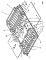
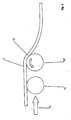
- the Figures 1 - 3 and 6 show a good 1, for example, a slice of sausage, cheese or meat, which rests on a surface, namely a conveyor belt 2.
- the conveyor belt 2 has moved the goods 1 in this position in the direction of the arrow.
- the device has on both sides of the conveyor belt 2 each a stationary frame structure 3, which (but for simplicity only provided on one side of the belt with reference numerals) by struts 4, associated U-shaped bracket 5, arranged on the bracket guide rods 6, and formed by two further struts 7, the latter connecting the two frame structures 3 with each other.
- a further box-shaped frame 8 is arranged centrally, which carries the bearing 29 of a sliding device, which by the two sides of the conveyor belt 2 and thus the goods 1 arranged sliding units 20, of which, for simplicity, only one with reference numerals is provided, can be moved back and forth (see the links below in FIG. 4 drawn arrows).
- These sliding units 20 are formed by struts 21, U-shaped bracket 22 and cross members 23.
- the transverse bars are provided with guide openings 24, through which the guide rods 6 of the frame structure 3 are guided. As a result, the sliding units 20 are movable back and forth on the guide rods 6.
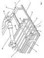
- the reciprocating movement is effected by a mounted on the bearing 29 on the plate 4 pivot lever 28 to which the piston rod of a pneumatically driven piston / cylinder assembly 30 engages, which is rotatably mounted on a boom 9 and thus supported on the frame structure 3.
- the boom 9 is connected to the U-shaped bracket 5 of the frame structure 3.
- the movement of the pivot lever 28 is transmitted by a toggle lever 31 on the cross members 23 and thus on the sliding units 20.
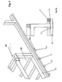
- rollers 10 are rotatably mounted in the struts 21, which are part of the sliding units 20.
- the struts 21 thus form the arranged on the sliding units 20 bearings for the rollers 10.
- On the free, outwardly projecting ends of the rollers 10 presses with a certain contact pressure in each case one of the struts 7, which, as mentioned, are part of the stationary frame structure 3 ,
- the struts 7 are provided on its underside with a friction lining 11.
- rollers 10 are rotated by the relative movement of the struts 7 in the counterclockwise direction, so that it is ensured that in the contact region 12 between the rollers 10 and the strut 7, the rollers 10 along its circumference rotate the same peripheral speed at which the rollers are pushed in the direction of the arrow A under the Good 1, so that only a lifting, but not caused by a force relative movement of the peripheral surface of the rotating roller 10 takes place against the Good 1 in the sliding direction.
- a flexible good such as a slice of sausage, cheese or meat, so is not pushed together or folded. The good has only so much stability that it does not fall between two consecutively arranged rollers 10 in the space.
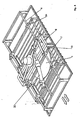
- FIG. 7 shows an embodiment in which only a stationary frame structure 3 and only a sliding unit 20 are provided, which attack from only one side of a good 1 object. Otherwise, the components correspond to those according to the Figures 1-6 ,
- the entire apparatus can be attached to a robot on the bearing 29, which has the form of a pin or a hub, and transported to another location.
Landscapes
- Engineering & Computer Science (AREA)
- Mechanical Engineering (AREA)
- Life Sciences & Earth Sciences (AREA)
- Food Science & Technology (AREA)
- Robotics (AREA)
- Rollers For Roller Conveyors For Transfer (AREA)
- Specific Conveyance Elements (AREA)
Description
- Die Erfindung betrifft eine Vorrichtung zur Aufnahme und zum Transport eines Gutes, die Aufnahmemittel aufweist, die durch eine Schiebeeinrichtung unter das Gut geschoben werden. Die Aufnahmemittel werden, nachdem sie das Gut von einer Unterlage, zum Beispiel einem Förderband, aufgehoben haben, von einem Roboter an eine andere Stelle bewegt und geben dort das Gut, zum Beispiel in eine Verpackungsschale wieder ab. Derartige Vorrichtungen sind zum Beispiel aus der
WO 99/0036 JP 57-151533 WO 2005/051812 bekannt. Der Transport derartiger Güter bereitet dann besondere Probleme, wenn diese so flexibel sind, dass sie beim Aufnehmen durch die Aufnahmemittel zusammengeschoben werden. Es sind dann besondere Maßnahmen zu treffen, um dieses zu vermeiden. - Aus der
GB 2 378 432 A - Eine ähnliche Anordnung, bei der jedoch die Platte nicht vertikal, sondern horizontal bewegt wird, ist in der
WO 2007/093774 A1 beschrieben. Dabei muss bei jedem Bewegungstakt eine das Band an einem Ende haltende Feder über die gesamte Bewegungsstrecke des Bandes gespannt werden. Ferner unterliegt das Band bei seiner Bewegung über die Platte einer Abnutzung infolge der Reibung an der Platte. - Eine weitere Vorrichtung der oben genannten Art ist in der eignen älteren deutschen Offentegungschrift
DE 10 2008 023 770 A1 der Anmelderin beschrieben. - Ferner ist aus der Druckschrift
US 1,464,513 A eine Vorrichtung zur Handhabung von flächigem Material gemäß dem Oberbegiff des Ansprüche 1 und 3 bekannt. - Aufgabe der vorliegenden Erfindung ist es, unter Vermeidung dieser Nachteile eine Vorrichtung der eingangs genannten Art zu schaffen, bei der die Aufnahme des Gutes einfacher und zuverlässiger erfolgt.
- Diese Aufgabe wird durch die Vorrichtungen der Ansprüche 1 und 3 gelöst.
- Vorteilhafte Weiterbildungen der Erfindung sind in den Unteransprüchen definiert.
- Die Rollen heben also das Gut, wenn sie sich unter das Gut schieben, etwas an, wobei jedoch zwischen Gut und Rollen in der Schieberichtung keine Relativbewegung auftritt, durch die Reibungskräfte erzeugt werden, die das Gut zusammenschieben könnten.
- Derartige Anordnungen sind nicht nur, wie oben bereits erwähnt, in der Nahrungsmittelindustrie einsetzbar, sondern auch beim Transport elektronischer Komponenten, die zwar starr sind, bei denen jede Art Relativbewegung zwischen Greifern und der Oberfläche vermieden werden muss, um die Oberflächen nicht zu verkratzen. Das sind zum Beispiel Halbleiter-Wafer.
- Ausführungsbeispiele der Erfindung und ihrer vorteilhaften Weiterbildungen werden unter Bezugnahme auf die beigefügten Zeichnungen im Folgenden beschrieben. Es stellen dar:
- Figur 1
- ein erstes Ausführungsbeispiel,
- Figur 2
- eine vergrößerte Darstellung des Bereiches 11 in
Figur 1 - Figur 3
- eine vergrößerte Darstellung des Bereiches 111 in
Figur 2 , - Figur 3a
- einen Schnitt in Richtung der Pfeile IIIa-IIIa in
Figur 3 , - Figur 4
- eine schematische Darstellung der Anordnung nach
Figur 1 , bei der Rollen 10 das Gut 1 bereits untergriffen haben, - Figur 5
- eine schematische Darstellung der Bewegungsverhältnisse im Bereich des Kontaktes der Rollen 10 mit dem Gut 1,
- Figur 6
- die Anordnung nach
Figur 1 in Seitenansicht, - Figur 7
- ein zweites Ausführungsbeispiel.
- Die
Figuren 1 - 3 und6 zeigen ein Gut 1, zum Beispiel eine Scheibe Wurst, Käse oder Fleisch, die auf einer Fläche, nämlich einem Förderband 2, aufliegt. Das Förderband 2 hat das Gut 1 in diese Position in Richtung des eingezeichneten Pfeils bewegt. - Die Vorrichtung weist beidseitig des Förderbandes 2 je eine stationäre Rahmenstruktur 3 auf, die (jedoch der Einfachheit halber nur auf einer Seite des Bandes mit Bezugszeichen versehen ist) durch Streben 4, damit verbundene U-förmige Bügel 5, an dem Bügel angeordnete Führungsstangen 6, sowie durch zwei weitere Streben 7 gebildet wird, wobei letztere die beiden Rahmenstrukturen 3 miteinander verbinden. Auf den beiden Streben 7 ist mittig ein weiterer kastenförmiger Rahmen 8 angeordnet, der das Lager 29 einer Schiebeeinrichtung trägt, die durch die zwei beidseitig des Förderbandes 2 und damit des Gutes 1 angeordnete Schiebeeinheiten 20, von denen jedoch der Einfachheit halber auch nur eine mit Bezugszeichen versehen ist, hin- und herbewegt werden können (vergleiche die links unten in
Figur 4 eingezeichneten Pfeile). Diese Schiebeeinheiten 20 werden durch Streben 21, U-förmige Bügel 22 und Querholme 23 gebildet. Die Querholme sind mit Führungsöffnungen 24 versehen, durch die die Führungsstangen 6 der Rahmenstruktur 3 hindurch geführt sind. Dadurch sind die Schiebeeinheiten 20 auf den Führungsstangen 6 hin- und her bewegbar. - Die Hin- und Herbewegung erfolgt durch einen am Lager 29 an der Platte 4 gelagerten Schwenkhebel 28, an dem die Kolbenstange einer pneumatisch angetriebenen Kolben/Zylinderanordnung 30 angreift, die auf einen Ausleger 9 drehbar gelagert und damit an der Rahmenstruktur 3 abgestützt ist. Der Ausleger 9 ist mit dem U-förmigen Bügel 5 der Rahmenstruktur 3 verbunden. Die Bewegung des Schwenkhebels 28 wird durch einen Kniehebel 31 auf die Querholme 23 und damit auf die Schiebeeinheiten 20 übertragen.
- Wie aus
Figur 3a zu ersehen, sind Rollen 10 in den Streben 21 drehbar gelagert, die Teil der Schiebeeinheiten 20 sind. Die Streben 21 bilden also die an den Schiebeinheiten 20 angeordneten Lager für die Rollen 10. Auf die freien, nach außen vorstehenden Enden der Rollen 10 drückt mit einem gewissen Anpressdruck jeweils eine der Streben 7, die, wie erwähnt, Teil der stationären Rahmensstruktur 3 sind. Die Streben 7 sind auf ihrer Unterseite mit einem Reibbelag 11 versehen. Wenn sich nun die Schiebeeinheit 20 und mit ihr die Strebe 21 durch pneumatische Betätigung der Kolben/Zylinderanordnung 30 bewegt, dann werden die Rollen 10 durch Verschiebung der Streben 7 und des Reibbelags 11 gedreht, und zwar derart, dass die Geschwindigkeit der Schiebeeinheit 20 gleich der Umfangsgeschwindigkeit der dadurch angetriebenen Rollen 10 ist. Der Antrieb der Rollen 10 kann auch - anstatt durch den Reibbelag 11 - durch Zahnstangen erfolgen, die mit den Streben 7 verbunden sind. Werden nun, wie ausFigur 4 ersichtlich, durch Betätigung der Kolben-/Zylindereinrichtung 30 die Rollen 10 aufeinander zu bewegt, so schieben sich die Rollen 10 in der ausFigur 5 ersichtlichen Weise in Richtung A unter das Gut 1. Die Rollen 10 werden durch die Relativbewegung der Streben 7 im Gegenuhrzeigersinn gedreht, so dass gewährleistet ist, dass in dem Berührungsbereich 12 zwischen den Rollen 10 und der Strebe 7 sich die Rollen 10 entlang ihres Umfangs mit derselben Umfangsgeschwindigkeit drehen, mit der die Rollen in Richtung des eingezeichneten Pfeils A unter das Gut 1 geschoben werden, so dass lediglich ein Anheben, jedoch keine durch eine Kraft verursachte Relativbewegung der Umfangsfläche der sich drehenden Rolle 10 gegenüber dem Gut 1 in Schieberichtung stattfindet. Ein flexibles Gut, wie zum Beispiel eine Scheibe Wurst, Käse oder Fleisch, wird also nicht zusammengeschoben oder gefaltet. Das Gut muss lediglich so viel Stabilität haben, dass es zwischen zwei aufeinander folgend angeordneten Rollen 10 nicht in den Zwischenraum fällt. -
Figur 7 zeigt ein Ausführungsbeispiel, bei dem lediglich eine stationäre Rahmenstruktur 3 und lediglich eine Schiebeeinheit 20 vorgesehen sind, die von nur einer Seite an einem Gut 1 Gegenstand angreifen. Ansonsten entsprechen die Bauteile denjenigen nach denFiguren 1 - 6 . - Die gesamte Vorrichtung kann an dem Lager 29, die die Form eines Zapfens oder einer Nabe hat, an einem Roboter befestigt und an einen anderen Ort transportiert werden.
-
- 1
- Gut
- 2
- Förderband
- 3
- stationäre Rahmenstruktur
- 4
- Streben
- 5
- U-förmiger Bügel
- 6
- Führungsstangen
- 7
- Streben
- 8
- kastenartiger Rahmen
- 9
- Ausleger
- 10
- Rollen
- 10'
- vorderste Rolle
- 11
- Reibbelag
- 12
- Berührungsbereich
- 20
- Schiebeeinheiten
- 21
- Streben
- 22
- U-förmiger Bügel
- 23
- Querholme
- 24
- Führungsöffnungen
- 28
- Schwenkhebel
- 29
- Lager
- 30
- Kolben-Zylinderanordnung
- 31
- Kniehebel
- A
- Schieberichtung
Claims (5)
- Vorrichtung zur Aufnahme und zum Transport eines Gutes (1), die eine stationäre Rahmenstruktur (3), eine dieser gegenüber verschiebbare Schiebeeinheit (20) und durch Rollen gebildete Aufnahmemittel aufweist, wobei die Rollen (10) an der Schiebeeinheit gelagert sind und quer zu der Richtung, in der die Rollen (10) durch die Schiebeeinheit (20) unter das Gut (1) geschoben werden können, angeordnet sind und wobei die Rollen (10) derart angetrieben werden, dass ihre Umfangsgeschwindigkeit gleich, jedoch der Richtung entgegengesetzt der Geschwindigkeit ist, mit der sie unter das Gut (1) geschoben werden, dadurch gekennzeichnet, dass der Antrieb der Rollen (10) durch Reibung erfolgt, die von einem Bauteil (7) der stationären Rahmenstruktur (3) auf die Rollen (10) übertragen wird.
- Vorrichtung nach Anspruch 1, dadurch gekennzeichnet, dass das Bauteil (7) einen Reibbelag (11) aufweist und an die Rollen (10) angedrückt wird.
- Vorrichtung zur Aufnahme und zum Transport eines Gutes (1), die eine stationäre Rahmenstruktur (3), eine dieser gegenüber verschiebbare Schiebeeinheit (20) und durch Rollen gebildete Aufnahmemittel aufweist, wobei die Rollen (10) an der Schiebeeinheit gelagert sind und quer zu der Richtung, in der die Rollen (10) durch die Schiebeeinheit (20) unter das Gut (1) geschoben werden können, angeordnet sind und wobei die Rollen (10) derart angetrieben werden, dass ihre Umfangsgeschwindigkeit gleich, jedoch der Richtung entgegengesetzt der Geschwindigkeit ist, mit der sie unter das Gut (1) geschoben werden, dadurch gekennzeichnet, dass der Antrieb der Rollen (10) durch eine an der stationären Rahmenstruktur (3) angeordnete Zahnstange erfolgt.
- Vorrichtung nach einem der vorgenannten Ansprüche, dadurch gekennzeichnet, dass mindestens die in Richtung der Bewegung der Schiebeeinheit (20) unter das Gut (1) vordere Rolle (10') angetrieben wird, und dass die nicht angetriebenen Rollen (10) frei drehbar sind.
- Vorrichtung nach einem der vorgenannten Ansprüche, dadurch gekennzeichnet, dass zu beiden Seiten des Gutes (1) eine Schiebeeinheit (20) angeordnet ist und beide Schiebeeinheiten (20) durch eine pneumatische Kolben-/Zylinderanordnung (30) aufeinander zu- und voneinander wegbewegt werden können.
Applications Claiming Priority (3)
| Application Number | Priority Date | Filing Date | Title |
|---|---|---|---|
| DE102007045042 | 2007-09-13 | ||
| DE102007058265 | 2007-11-27 | ||
| DE102008023770A DE102008023770A1 (de) | 2007-09-13 | 2008-05-09 | Vorrichtung zur Aufnahme und zum Transport eines Gutes |
Publications (2)
| Publication Number | Publication Date |
|---|---|
| EP2036840A1 EP2036840A1 (de) | 2009-03-18 |
| EP2036840B1 true EP2036840B1 (de) | 2010-04-07 |
Family
ID=39884111
Family Applications (1)
| Application Number | Title | Priority Date | Filing Date |
|---|---|---|---|
| EP20080015815 Not-in-force EP2036840B1 (de) | 2007-09-13 | 2008-09-09 | Vorrichtung zur Aufnahme und zum Transport eines Gutes |
Country Status (1)
| Country | Link |
|---|---|
| EP (1) | EP2036840B1 (de) |
Families Citing this family (1)
| Publication number | Priority date | Publication date | Assignee | Title |
|---|---|---|---|---|
| CN109896275A (zh) * | 2019-03-14 | 2019-06-18 | 北京卫星环境工程研究所 | 多规格料箱快速抓取方法及装置 |
Family Cites Families (4)
| Publication number | Priority date | Publication date | Assignee | Title |
|---|---|---|---|---|
| US1464513A (en) | 1919-10-31 | 1923-08-14 | Agasote Millboard Co | Sheet-handling device |
| DD145257A1 (de) * | 1979-09-07 | 1980-12-03 | Harald Jesch | Greifer zum be-und entpalettieren von insbesondere flaschenkaestenlagen |
| FR2697006B1 (fr) * | 1992-10-19 | 1995-01-06 | Newtec Int | Grappin de manutention de charges, comme des sacs, et palettiseur comportant un tel grappin. |
| GB0603002D0 (en) * | 2006-02-15 | 2006-03-29 | Aew Delford Group Ltd | Improved pick and place handling device |
-
2008
- 2008-09-09 EP EP20080015815 patent/EP2036840B1/de not_active Not-in-force
Also Published As
| Publication number | Publication date |
|---|---|
| EP2036840A1 (de) | 2009-03-18 |
Similar Documents
| Publication | Publication Date | Title |
|---|---|---|
| DE1561728B2 (de) | Bogenfoerdervorrichtung | |
| DE102008023762A1 (de) | Vorrichtung zur Aufnahme und zum Transport eines Gutes | |
| DE4101399A1 (de) | Vorrichtung zum falten von blaettern | |
| DE102007001800A1 (de) | Vorrichtung zum Transport von Druckprodukten | |
| DE102011105894B4 (de) | Sortier- und/oder Förder- und/oder Verpackungsanlage | |
| DE69831433T2 (de) | Förderer mit deformierbarem Förderband | |
| DE2517015C2 (de) | Rollenbahn zum Fördern und Stauen von Stückgut | |
| EP2743041A1 (de) | Greifer für Lebensmittelportionen mit flexiblem Flächenelement | |
| WO2017185192A1 (de) | Fördereinrichtung mit einem förderorgan | |
| DE102008023770A1 (de) | Vorrichtung zur Aufnahme und zum Transport eines Gutes | |
| EP1667907A1 (de) | System zum be- und entladen eines laderaums, insbesondere des flugzeugs, mit st ckgut | |
| DE9209615U1 (de) | Drehvorrichtung für Papierbogen in einer Förderbahn | |
| DE202008000083U1 (de) | Vorrichtung zur Herstellung von gerollten Speisen mit oder ohne Füllung | |
| EP2036841B1 (de) | Vorrichtung zur Aufnahme und zum Transport eines Gutes | |
| DE2519420C3 (de) | Falzvorrichtung | |
| EP3031759B1 (de) | Vorrichtung und dazugehöriges verfahren zum fördern und transferieren von flexiblen flächigen gegenständen | |
| DE1951598B2 (de) | Ausweichspur für eine Arbeitsvorrichtung enthaltende Fertigungsstraßen | |
| EP2036840A1 (de) | Vorrichtung zur Aufnahme und zum Transport eines Gutes | |
| EP3245148B1 (de) | Förderorgan mit rollenmechanismus | |
| AT513308B1 (de) | Auswiegeanordnung zum Verschieben von Teigportionen | |
| EP0594090B1 (de) | Positioniervorrichtung für Stückgut | |
| DE1923441A1 (de) | Arbeitsverfahren und Einrichtung zum kontinuierlichen Foerdern,Stapeln und Entstapeln von tafelfoermigem Foerdergut | |
| DE19948704C1 (de) | Vorrichtung zum Drehen eines Papierstapels | |
| DE4112499C2 (de) | Vorrichtung zum Transportieren von mittels einer Füllmaschine gefüllten Säcken | |
| DE202019106430U1 (de) | Selbstzentrierende Fördereinrichtung |
Legal Events
| Date | Code | Title | Description |
|---|---|---|---|
| PUAI | Public reference made under article 153(3) epc to a published international application that has entered the european phase |
Free format text: ORIGINAL CODE: 0009012 |
|
| AK | Designated contracting states |
Kind code of ref document: A1 Designated state(s): AT BE BG CH CY CZ DE DK EE ES FI FR GB GR HR HU IE IS IT LI LT LU LV MC MT NL NO PL PT RO SE SI SK TR |
|
| AX | Request for extension of the european patent |
Extension state: AL BA MK RS |
|
| 17P | Request for examination filed |
Effective date: 20090424 |
|
| 17Q | First examination report despatched |
Effective date: 20090626 |
|
| GRAP | Despatch of communication of intention to grant a patent |
Free format text: ORIGINAL CODE: EPIDOSNIGR1 |
|
| AKX | Designation fees paid |
Designated state(s): AT BE BG CH CY CZ DE DK EE ES FI FR GB GR HR HU IE IS IT LI LT LU LV MC MT NL NO PL PT RO SE SI SK TR |
|
| GRAS | Grant fee paid |
Free format text: ORIGINAL CODE: EPIDOSNIGR3 |
|
| GRAA | (expected) grant |
Free format text: ORIGINAL CODE: 0009210 |
|
| AK | Designated contracting states |
Kind code of ref document: B1 Designated state(s): AT BE BG CH CY CZ DE DK EE ES FI FR GB GR HR HU IE IS IT LI LT LU LV MC MT NL NO PL PT RO SE SI SK TR |
|
| REG | Reference to a national code |
Ref country code: GB Ref legal event code: FG4D Free format text: NOT ENGLISH |
|
| REG | Reference to a national code |
Ref country code: CH Ref legal event code: EP |
|
| REG | Reference to a national code |
Ref country code: IE Ref legal event code: FG4D Free format text: LANGUAGE OF EP DOCUMENT: GERMAN |
|
| REF | Corresponds to: |
Ref document number: 502008000522 Country of ref document: DE Date of ref document: 20100520 Kind code of ref document: P |
|
| REG | Reference to a national code |
Ref country code: ES Ref legal event code: FG2A Ref document number: 2341056 Country of ref document: ES Kind code of ref document: T3 |
|
| REG | Reference to a national code |
Ref country code: CH Ref legal event code: NV Representative=s name: R. A. EGLI & CO. PATENTANWAELTE |
|
| REG | Reference to a national code |
Ref country code: NL Ref legal event code: T3 |
|
| PG25 | Lapsed in a contracting state [announced via postgrant information from national office to epo] |
Ref country code: SI Free format text: LAPSE BECAUSE OF FAILURE TO SUBMIT A TRANSLATION OF THE DESCRIPTION OR TO PAY THE FEE WITHIN THE PRESCRIBED TIME-LIMIT Effective date: 20100407 |
|
| LTIE | Lt: invalidation of european patent or patent extension |
Effective date: 20100407 |
|
| REG | Reference to a national code |
Ref country code: IE Ref legal event code: FD4D |
|
| PG25 | Lapsed in a contracting state [announced via postgrant information from national office to epo] |
Ref country code: SE Free format text: LAPSE BECAUSE OF FAILURE TO SUBMIT A TRANSLATION OF THE DESCRIPTION OR TO PAY THE FEE WITHIN THE PRESCRIBED TIME-LIMIT Effective date: 20100407 Ref country code: NO Free format text: LAPSE BECAUSE OF FAILURE TO SUBMIT A TRANSLATION OF THE DESCRIPTION OR TO PAY THE FEE WITHIN THE PRESCRIBED TIME-LIMIT Effective date: 20100707 Ref country code: LT Free format text: LAPSE BECAUSE OF FAILURE TO SUBMIT A TRANSLATION OF THE DESCRIPTION OR TO PAY THE FEE WITHIN THE PRESCRIBED TIME-LIMIT Effective date: 20100407 |
|
| PG25 | Lapsed in a contracting state [announced via postgrant information from national office to epo] |
Ref country code: HR Free format text: LAPSE BECAUSE OF FAILURE TO SUBMIT A TRANSLATION OF THE DESCRIPTION OR TO PAY THE FEE WITHIN THE PRESCRIBED TIME-LIMIT Effective date: 20100407 Ref country code: LV Free format text: LAPSE BECAUSE OF FAILURE TO SUBMIT A TRANSLATION OF THE DESCRIPTION OR TO PAY THE FEE WITHIN THE PRESCRIBED TIME-LIMIT Effective date: 20100407 Ref country code: IS Free format text: LAPSE BECAUSE OF FAILURE TO SUBMIT A TRANSLATION OF THE DESCRIPTION OR TO PAY THE FEE WITHIN THE PRESCRIBED TIME-LIMIT Effective date: 20100807 Ref country code: FI Free format text: LAPSE BECAUSE OF FAILURE TO SUBMIT A TRANSLATION OF THE DESCRIPTION OR TO PAY THE FEE WITHIN THE PRESCRIBED TIME-LIMIT Effective date: 20100407 |
|
| PG25 | Lapsed in a contracting state [announced via postgrant information from national office to epo] |
Ref country code: CY Free format text: LAPSE BECAUSE OF FAILURE TO SUBMIT A TRANSLATION OF THE DESCRIPTION OR TO PAY THE FEE WITHIN THE PRESCRIBED TIME-LIMIT Effective date: 20100609 Ref country code: PL Free format text: LAPSE BECAUSE OF FAILURE TO SUBMIT A TRANSLATION OF THE DESCRIPTION OR TO PAY THE FEE WITHIN THE PRESCRIBED TIME-LIMIT Effective date: 20100407 |
|
| PG25 | Lapsed in a contracting state [announced via postgrant information from national office to epo] |
Ref country code: DK Free format text: LAPSE BECAUSE OF FAILURE TO SUBMIT A TRANSLATION OF THE DESCRIPTION OR TO PAY THE FEE WITHIN THE PRESCRIBED TIME-LIMIT Effective date: 20100407 Ref country code: IE Free format text: LAPSE BECAUSE OF FAILURE TO SUBMIT A TRANSLATION OF THE DESCRIPTION OR TO PAY THE FEE WITHIN THE PRESCRIBED TIME-LIMIT Effective date: 20100407 Ref country code: EE Free format text: LAPSE BECAUSE OF FAILURE TO SUBMIT A TRANSLATION OF THE DESCRIPTION OR TO PAY THE FEE WITHIN THE PRESCRIBED TIME-LIMIT Effective date: 20100407 |
|
| PLBE | No opposition filed within time limit |
Free format text: ORIGINAL CODE: 0009261 |
|
| STAA | Information on the status of an ep patent application or granted ep patent |
Free format text: STATUS: NO OPPOSITION FILED WITHIN TIME LIMIT |
|
| PG25 | Lapsed in a contracting state [announced via postgrant information from national office to epo] |
Ref country code: CZ Free format text: LAPSE BECAUSE OF FAILURE TO SUBMIT A TRANSLATION OF THE DESCRIPTION OR TO PAY THE FEE WITHIN THE PRESCRIBED TIME-LIMIT Effective date: 20100407 Ref country code: SK Free format text: LAPSE BECAUSE OF FAILURE TO SUBMIT A TRANSLATION OF THE DESCRIPTION OR TO PAY THE FEE WITHIN THE PRESCRIBED TIME-LIMIT Effective date: 20100407 Ref country code: RO Free format text: LAPSE BECAUSE OF FAILURE TO SUBMIT A TRANSLATION OF THE DESCRIPTION OR TO PAY THE FEE WITHIN THE PRESCRIBED TIME-LIMIT Effective date: 20100407 |
|
| 26N | No opposition filed |
Effective date: 20110110 |
|
| BERE | Be: lapsed |
Owner name: MULTIVAC SEPP HAGGENMULLER G.M.B.H. & CO. KG Effective date: 20100930 |
|
| PG25 | Lapsed in a contracting state [announced via postgrant information from national office to epo] |
Ref country code: MC Free format text: LAPSE BECAUSE OF NON-PAYMENT OF DUE FEES Effective date: 20100930 |
|
| PG25 | Lapsed in a contracting state [announced via postgrant information from national office to epo] |
Ref country code: GR Free format text: LAPSE BECAUSE OF FAILURE TO SUBMIT A TRANSLATION OF THE DESCRIPTION OR TO PAY THE FEE WITHIN THE PRESCRIBED TIME-LIMIT Effective date: 20100708 |
|
| PG25 | Lapsed in a contracting state [announced via postgrant information from national office to epo] |
Ref country code: BE Free format text: LAPSE BECAUSE OF NON-PAYMENT OF DUE FEES Effective date: 20100930 |
|
| PG25 | Lapsed in a contracting state [announced via postgrant information from national office to epo] |
Ref country code: MT Free format text: LAPSE BECAUSE OF FAILURE TO SUBMIT A TRANSLATION OF THE DESCRIPTION OR TO PAY THE FEE WITHIN THE PRESCRIBED TIME-LIMIT Effective date: 20100407 |
|
| PG25 | Lapsed in a contracting state [announced via postgrant information from national office to epo] |
Ref country code: LU Free format text: LAPSE BECAUSE OF NON-PAYMENT OF DUE FEES Effective date: 20100909 Ref country code: BG Free format text: LAPSE BECAUSE OF FAILURE TO SUBMIT A TRANSLATION OF THE DESCRIPTION OR TO PAY THE FEE WITHIN THE PRESCRIBED TIME-LIMIT Effective date: 20100407 Ref country code: HU Free format text: LAPSE BECAUSE OF FAILURE TO SUBMIT A TRANSLATION OF THE DESCRIPTION OR TO PAY THE FEE WITHIN THE PRESCRIBED TIME-LIMIT Effective date: 20101008 |
|
| PG25 | Lapsed in a contracting state [announced via postgrant information from national office to epo] |
Ref country code: TR Free format text: LAPSE BECAUSE OF FAILURE TO SUBMIT A TRANSLATION OF THE DESCRIPTION OR TO PAY THE FEE WITHIN THE PRESCRIBED TIME-LIMIT Effective date: 20100407 |
|
| PGFP | Annual fee paid to national office [announced via postgrant information from national office to epo] |
Ref country code: ES Payment date: 20120907 Year of fee payment: 5 Ref country code: IT Payment date: 20120922 Year of fee payment: 5 |
|
| PGFP | Annual fee paid to national office [announced via postgrant information from national office to epo] |
Ref country code: FR Payment date: 20121011 Year of fee payment: 5 Ref country code: CH Payment date: 20121001 Year of fee payment: 5 |
|
| PGFP | Annual fee paid to national office [announced via postgrant information from national office to epo] |
Ref country code: NL Payment date: 20120917 Year of fee payment: 5 |
|
| PG25 | Lapsed in a contracting state [announced via postgrant information from national office to epo] |
Ref country code: PT Free format text: LAPSE BECAUSE OF NON-PAYMENT OF DUE FEES Effective date: 20100407 |
|
| PG25 | Lapsed in a contracting state [announced via postgrant information from national office to epo] |
Ref country code: BG Free format text: LAPSE BECAUSE OF FAILURE TO SUBMIT A TRANSLATION OF THE DESCRIPTION OR TO PAY THE FEE WITHIN THE PRESCRIBED TIME-LIMIT Effective date: 20100707 |
|
| REG | Reference to a national code |
Ref country code: NL Ref legal event code: V1 Effective date: 20140401 |
|
| REG | Reference to a national code |
Ref country code: CH Ref legal event code: PL |
|
| REG | Reference to a national code |
Ref country code: FR Ref legal event code: ST Effective date: 20140530 |
|
| PG25 | Lapsed in a contracting state [announced via postgrant information from national office to epo] |
Ref country code: LI Free format text: LAPSE BECAUSE OF NON-PAYMENT OF DUE FEES Effective date: 20130930 Ref country code: CH Free format text: LAPSE BECAUSE OF NON-PAYMENT OF DUE FEES Effective date: 20130930 |
|
| PG25 | Lapsed in a contracting state [announced via postgrant information from national office to epo] |
Ref country code: IT Free format text: LAPSE BECAUSE OF NON-PAYMENT OF DUE FEES Effective date: 20130909 Ref country code: FR Free format text: LAPSE BECAUSE OF NON-PAYMENT OF DUE FEES Effective date: 20130930 Ref country code: NL Free format text: LAPSE BECAUSE OF NON-PAYMENT OF DUE FEES Effective date: 20140401 |
|
| REG | Reference to a national code |
Ref country code: ES Ref legal event code: FD2A Effective date: 20141010 |
|
| REG | Reference to a national code |
Ref country code: AT Ref legal event code: MM01 Ref document number: 463456 Country of ref document: AT Kind code of ref document: T Effective date: 20130909 |
|
| PG25 | Lapsed in a contracting state [announced via postgrant information from national office to epo] |
Ref country code: ES Free format text: LAPSE BECAUSE OF NON-PAYMENT OF DUE FEES Effective date: 20130910 |
|
| PG25 | Lapsed in a contracting state [announced via postgrant information from national office to epo] |
Ref country code: AT Free format text: LAPSE BECAUSE OF NON-PAYMENT OF DUE FEES Effective date: 20130909 |
|
| REG | Reference to a national code |
Ref country code: DE Ref legal event code: R082 Ref document number: 502008000522 Country of ref document: DE Representative=s name: GRUENECKER PATENT- UND RECHTSANWAELTE PARTG MB, DE Ref country code: DE Ref legal event code: R081 Ref document number: 502008000522 Country of ref document: DE Owner name: MULTIVAC SEPP HAGGENMUELLER SE & CO. KG, DE Free format text: FORMER OWNER: MULTIVAC SEPP HAGGENMUELLER GMBH & CO. KG, 87787 WOLFERTSCHWENDEN, DE |
|
| PGFP | Annual fee paid to national office [announced via postgrant information from national office to epo] |
Ref country code: DE Payment date: 20180924 Year of fee payment: 11 |
|
| PGFP | Annual fee paid to national office [announced via postgrant information from national office to epo] |
Ref country code: GB Payment date: 20180924 Year of fee payment: 11 |
|
| REG | Reference to a national code |
Ref country code: DE Ref legal event code: R119 Ref document number: 502008000522 Country of ref document: DE |
|
| PG25 | Lapsed in a contracting state [announced via postgrant information from national office to epo] |
Ref country code: DE Free format text: LAPSE BECAUSE OF NON-PAYMENT OF DUE FEES Effective date: 20200401 |
|
| GBPC | Gb: european patent ceased through non-payment of renewal fee |
Effective date: 20190909 |
|
| PG25 | Lapsed in a contracting state [announced via postgrant information from national office to epo] |
Ref country code: GB Free format text: LAPSE BECAUSE OF NON-PAYMENT OF DUE FEES Effective date: 20190909 |