EP2032066B1 - Robotergesteuerte positionierungs- und bewegungseinrichtung für ein organ oder instrument und behandlungseinrichtung enthaltend eine solche einrichtung - Google Patents
Robotergesteuerte positionierungs- und bewegungseinrichtung für ein organ oder instrument und behandlungseinrichtung enthaltend eine solche einrichtung Download PDFInfo
- Publication number
- EP2032066B1 EP2032066B1 EP07803940.1A EP07803940A EP2032066B1 EP 2032066 B1 EP2032066 B1 EP 2032066B1 EP 07803940 A EP07803940 A EP 07803940A EP 2032066 B1 EP2032066 B1 EP 2032066B1
- Authority
- EP
- European Patent Office
- Prior art keywords
- patient
- sub
- assembly
- probe
- installation
- Prior art date
- Legal status (The legal status is an assumption and is not a legal conclusion. Google has not performed a legal analysis and makes no representation as to the accuracy of the status listed.)
- Active
Links
- 238000009434 installation Methods 0.000 title claims description 73
- 230000033001 locomotion Effects 0.000 title claims description 39
- 239000000523 sample Substances 0.000 claims description 76
- 210000003128 head Anatomy 0.000 claims description 48
- 230000000638 stimulation Effects 0.000 claims description 23
- 238000011491 transcranial magnetic stimulation Methods 0.000 claims description 23
- 230000007246 mechanism Effects 0.000 claims description 20
- 238000013519 translation Methods 0.000 claims description 8
- 230000005540 biological transmission Effects 0.000 claims description 6
- 239000000470 constituent Substances 0.000 claims description 6
- 210000003625 skull Anatomy 0.000 claims description 4
- 210000001061 forehead Anatomy 0.000 claims description 3
- 238000012544 monitoring process Methods 0.000 claims 2
- 238000000429 assembly Methods 0.000 claims 1
- 238000006073 displacement reaction Methods 0.000 description 19
- 238000000034 method Methods 0.000 description 15
- 210000000056 organ Anatomy 0.000 description 7
- 241001080024 Telles Species 0.000 description 6
- 210000000707 wrist Anatomy 0.000 description 5
- 238000001816 cooling Methods 0.000 description 4
- 230000003287 optical effect Effects 0.000 description 4
- 210000004556 brain Anatomy 0.000 description 3
- 238000004364 calculation method Methods 0.000 description 3
- 210000003710 cerebral cortex Anatomy 0.000 description 3
- 230000001054 cortical effect Effects 0.000 description 3
- 238000003384 imaging method Methods 0.000 description 3
- 238000005096 rolling process Methods 0.000 description 3
- 238000001228 spectrum Methods 0.000 description 3
- RYGMFSIKBFXOCR-UHFFFAOYSA-N Copper Chemical compound [Cu] RYGMFSIKBFXOCR-UHFFFAOYSA-N 0.000 description 2
- 238000004458 analytical method Methods 0.000 description 2
- 238000010276 construction Methods 0.000 description 2
- 229910052802 copper Inorganic materials 0.000 description 2
- 239000010949 copper Substances 0.000 description 2
- 238000010586 diagram Methods 0.000 description 2
- 238000002599 functional magnetic resonance imaging Methods 0.000 description 2
- 230000002452 interceptive effect Effects 0.000 description 2
- 238000011835 investigation Methods 0.000 description 2
- 238000002595 magnetic resonance imaging Methods 0.000 description 2
- 238000007726 management method Methods 0.000 description 2
- 230000005855 radiation Effects 0.000 description 2
- 230000000007 visual effect Effects 0.000 description 2
- 238000004804 winding Methods 0.000 description 2
- 208000019901 Anxiety disease Diseases 0.000 description 1
- 241000050051 Chelone glabra Species 0.000 description 1
- 208000021384 Obsessive-Compulsive disease Diseases 0.000 description 1
- 230000002730 additional effect Effects 0.000 description 1
- 230000036506 anxiety Effects 0.000 description 1
- 230000000903 blocking effect Effects 0.000 description 1
- 210000004027 cell Anatomy 0.000 description 1
- 230000008859 change Effects 0.000 description 1
- 239000004020 conductor Substances 0.000 description 1
- 238000000354 decomposition reaction Methods 0.000 description 1
- 238000013461 design Methods 0.000 description 1
- 230000001627 detrimental effect Effects 0.000 description 1
- 238000002059 diagnostic imaging Methods 0.000 description 1
- 208000037265 diseases, disorders, signs and symptoms Diseases 0.000 description 1
- 210000005069 ears Anatomy 0.000 description 1
- 239000012636 effector Substances 0.000 description 1
- 230000001037 epileptic effect Effects 0.000 description 1
- 230000005284 excitation Effects 0.000 description 1
- 238000009432 framing Methods 0.000 description 1
- 238000010438 heat treatment Methods 0.000 description 1
- 230000004807 localization Effects 0.000 description 1
- 239000003550 marker Substances 0.000 description 1
- 239000002184 metal Substances 0.000 description 1
- 229910052751 metal Inorganic materials 0.000 description 1
- 238000012986 modification Methods 0.000 description 1
- 230000004048 modification Effects 0.000 description 1
- 238000005457 optimization Methods 0.000 description 1
- 230000007170 pathology Effects 0.000 description 1
- 230000008569 process Effects 0.000 description 1
- 238000012545 processing Methods 0.000 description 1
- 238000012797 qualification Methods 0.000 description 1
- 230000009467 reduction Effects 0.000 description 1
- 201000000980 schizophrenia Diseases 0.000 description 1
- 210000002966 serum Anatomy 0.000 description 1
- 238000006467 substitution reaction Methods 0.000 description 1
- 230000001629 suppression Effects 0.000 description 1
- 238000001356 surgical procedure Methods 0.000 description 1
- 210000001835 viscera Anatomy 0.000 description 1
- 230000002747 voluntary effect Effects 0.000 description 1
Images


Classifications
-
- A—HUMAN NECESSITIES
- A61—MEDICAL OR VETERINARY SCIENCE; HYGIENE
- A61B—DIAGNOSIS; SURGERY; IDENTIFICATION
- A61B6/00—Apparatus or devices for radiation diagnosis; Apparatus or devices for radiation diagnosis combined with radiation therapy equipment
- A61B6/44—Constructional features of apparatus for radiation diagnosis
- A61B6/4429—Constructional features of apparatus for radiation diagnosis related to the mounting of source units and detector units
- A61B6/4435—Constructional features of apparatus for radiation diagnosis related to the mounting of source units and detector units the source unit and the detector unit being coupled by a rigid structure
- A61B6/4441—Constructional features of apparatus for radiation diagnosis related to the mounting of source units and detector units the source unit and the detector unit being coupled by a rigid structure the rigid structure being a C-arm or U-arm
-
- A—HUMAN NECESSITIES
- A61—MEDICAL OR VETERINARY SCIENCE; HYGIENE
- A61B—DIAGNOSIS; SURGERY; IDENTIFICATION
- A61B34/00—Computer-aided surgery; Manipulators or robots specially adapted for use in surgery
- A61B34/30—Surgical robots
-
- A—HUMAN NECESSITIES
- A61—MEDICAL OR VETERINARY SCIENCE; HYGIENE
- A61B—DIAGNOSIS; SURGERY; IDENTIFICATION
- A61B34/00—Computer-aided surgery; Manipulators or robots specially adapted for use in surgery
- A61B34/70—Manipulators specially adapted for use in surgery
- A61B34/71—Manipulators operated by drive cable mechanisms
-
- A—HUMAN NECESSITIES
- A61—MEDICAL OR VETERINARY SCIENCE; HYGIENE
- A61B—DIAGNOSIS; SURGERY; IDENTIFICATION
- A61B34/00—Computer-aided surgery; Manipulators or robots specially adapted for use in surgery
- A61B34/70—Manipulators specially adapted for use in surgery
- A61B34/76—Manipulators having means for providing feel, e.g. force or tactile feedback
-
- A—HUMAN NECESSITIES
- A61—MEDICAL OR VETERINARY SCIENCE; HYGIENE
- A61B—DIAGNOSIS; SURGERY; IDENTIFICATION
- A61B90/00—Instruments, implements or accessories specially adapted for surgery or diagnosis and not covered by any of the groups A61B1/00 - A61B50/00, e.g. for luxation treatment or for protecting wound edges
- A61B90/06—Measuring instruments not otherwise provided for
- A61B2090/064—Measuring instruments not otherwise provided for for measuring force, pressure or mechanical tension
- A61B2090/065—Measuring instruments not otherwise provided for for measuring force, pressure or mechanical tension for measuring contact or contact pressure
-
- A—HUMAN NECESSITIES
- A61—MEDICAL OR VETERINARY SCIENCE; HYGIENE
- A61B—DIAGNOSIS; SURGERY; IDENTIFICATION
- A61B6/00—Apparatus or devices for radiation diagnosis; Apparatus or devices for radiation diagnosis combined with radiation therapy equipment
- A61B6/44—Constructional features of apparatus for radiation diagnosis
- A61B6/4488—Means for cooling
-
- A—HUMAN NECESSITIES
- A61—MEDICAL OR VETERINARY SCIENCE; HYGIENE
- A61B—DIAGNOSIS; SURGERY; IDENTIFICATION
- A61B6/00—Apparatus or devices for radiation diagnosis; Apparatus or devices for radiation diagnosis combined with radiation therapy equipment
- A61B6/54—Control of apparatus or devices for radiation diagnosis
- A61B6/548—Remote control of the apparatus or devices
-
- A—HUMAN NECESSITIES
- A61—MEDICAL OR VETERINARY SCIENCE; HYGIENE
- A61B—DIAGNOSIS; SURGERY; IDENTIFICATION
- A61B90/00—Instruments, implements or accessories specially adapted for surgery or diagnosis and not covered by any of the groups A61B1/00 - A61B50/00, e.g. for luxation treatment or for protecting wound edges
- A61B90/10—Instruments, implements or accessories specially adapted for surgery or diagnosis and not covered by any of the groups A61B1/00 - A61B50/00, e.g. for luxation treatment or for protecting wound edges for stereotaxic surgery, e.g. frame-based stereotaxis
-
- A—HUMAN NECESSITIES
- A61—MEDICAL OR VETERINARY SCIENCE; HYGIENE
- A61N—ELECTROTHERAPY; MAGNETOTHERAPY; RADIATION THERAPY; ULTRASOUND THERAPY
- A61N2/00—Magnetotherapy
- A61N2/004—Magnetotherapy specially adapted for a specific therapy
- A61N2/006—Magnetotherapy specially adapted for a specific therapy for magnetic stimulation of nerve tissue
Definitions
- the present invention relates to the field of robotic devices and devices with high accuracy and very good safety of use, allowing their implementation in a medical context.
- the present invention more particularly relates to a robotic installation for positioning and moving a transcranial magnetic stimulation probe member, a transcranial magnetic stimulation apparatus comprising such a robotic installation and can be used in the context of a method of transcranial magnetic stimulation using the aforementioned apparatus.
- the operator must necessarily be a specialized person, that is to say generally a surgeon, a neurologist, a radiologist or a similar specialist depending on the organs involved and the type of treatment or investigation to be performed.
- the probe incorporating the magnetic stimulation coil must be manually moved on the head of the patient by the neurologist in order to follow a precise trajectory in space.
- This structure controlled automatically or remotely controlled by an operator, comprises a telescopic stem at the end of which is suspended, via a rotoid connection, an articulated subassembly carrying the probe.
- the subassembly itself comprises a movable circular rail whose one end is secured, via a rotoid connection, a slide rail on which is mounted, slidably, the probe.
- this structure does not allow to sweep back and forth on the patient's head, and it should complete the said structure by two additional degrees of mobility in translation in a horizontal plane to be able to scan the entire surface upper skull.
- the present invention aims to overcome at least some of the disadvantages described above and to propose a robotic solution by the various manipulations mentioned above, relatively simple to control and meeting the required criteria of accuracy and safety.
- TMS transcranial magnetic stimulation
- the invention proposes a robotic installation according to the preamble of claim 1, further having the characteristics of the characterizing part of this claim.
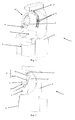
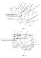
- the latter show a robotic installation 1 for the guided and controlled positioning and movement of a treatment organ or instrument 2, of the transcranial magnetic stimulation probe type or the like, at or around the head 3 of a patient 3 ' .
- This installation 1 essentially comprises a support structure (frame) 4, coated with a covering and protection casing 4 'and on which are mounted the constituent elements 7 to 31 of a robotic device 5 forming a series kinematic chain and bearing at its free end and controlled in position the probe 2 above.
- an adjustable device 6 for supporting and holding the patient 3 ', substantially in a sitting position, is part of or is associated with said support structure 4.
- said robotic device 5 consists of three 7, 7 ', 7 "mutually associated kinematic subassemblies, comprising, on the one hand, a first subassembly 7 in the form of a rotary articulation mechanism 8, 8 ', 8 ", secured to the support structure 4 by a first hinge 8 and corresponding to a spherical kinematic arrangement of the series type with three degrees of freedom, the hinge elements 8, 8', 8 "being all located outside the volume 9 capable of receiving the patient 3 'and their axes of rotation axis 1, axis 2 and axis 3 being concurrent in a focal point PF substantially corresponding to the hypothetical center of the head 3 of the patient 3' in second intervention position, a second subassembly 7 'in the form of a linear translation mechanism along an axis (axis 4) passing through the aforementioned FP focal point and secured to the movable portion 10 of the third 8 "articulation in serum ie of the first subassembl
- the decomposition of the robotic device 5 into three subassemblies 7, 7 ', 7 "independent and connected together in series facilitates the control in position and in displacement, increases the precision of the resulting movement and makes it possible to individually secure each of the articulating elements that constitute it.
- a first subassembly 7 with a spherical motion formed of three rotary or rotoidal links in series (8 / axis 1, 8 '/ axis 2, 8 "/ axis 3) and not interfering with the volume 9 receiving the patient 3 ', with a second subset 7' to move in translation along an axis (axis 4) radial with respect to the sphere or the sphere portion whose points can be reached by means of the first subset 7, allows optimized management of the security of the robotic device 5, possibly by the only secure control of the second subset 7 '.
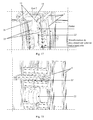
- the first rotary joint 8 of the first subassembly 7 consists of a circular slide connection, comprising a guide rail 13, preferably a double rail, in the shape of a circular arc, substantially semicircular, integral with the support structure 4, and a movable carriage 14 adapted to circulate on said rail 13, and whose displacement is controlled by a transmission linkage 15 connected to an actuator 16, the circular movement being effected in the median plane of the patient 3 in the position of intervention and said guide rail 13 having a positioning and an extension such that it extends around the head 3 of said patient 3 'substantially from the rear base of the skull to the front.
- the rail 13 is fixed rigidly in several places to the support structure 4, at the level of a stem-shaped upper part overlooking the patient support and holding device, in the form of an adjustable seat 6.
- the rail 13 may have either a double structure ( Figures 1 to 3 , 7 to 9 , 17 , 19 and 20 ), a single rail structure ( Figures 5A, 5B and 14 ).
- the carriage 14 circulates, at the level of adapted grooves, on the two identical rails and parallel to each other by means of rolling shoes or portions of slides located on either side of said carriage 14, and in the second aforementioned case, the carriage 14 circulates on the single rail by means of at least two rolling or sliding skids located one after the other, on one side.
- the transmission linkage 15, realizing the displacement of the carriage 14 on the rail 13, can comprise, as can be seen from Figures 5A and 5B a pair of rods connected to the carriage 14 at one end and a second carriage sliding vertically in the support structure 14 at the other end.
- This second carriage can be driven in translation by the motor 16 by means of a ball screw and an endless lead screw engaging said second carriage at a threaded nut ( Figure 5B ).
- a first subset 7 of spherical articulated series type mechanism with three degrees of freedom is particularly suitable for a spherical work volume, such as the space surrounding the head of a patient, the positioning of the patient. the probe 2 being made at a sphere centered on the patient's head.
- the subassembly 7 consists according to the invention in a particular arrangement of circular guides (two concentric circular guide subassemblies connected to each other by an axis of rotation), thus avoiding any interference with the patient and optimizing the rigidity of the device for facilitate accurate handling of the probe 2.
- the second rotary articulation 8 'of the first subassembly 7 consists of an axial articulation with a shaft 17 rotatably mounted in a bearing 18 formed in the mobile carriage 14 forming part of the first rotary joint 8, the rotational displacement of said shaft being controlled by an actuator 19, for example a motor - gear unit, carried by said carriage 14.
- the third rotary joint 8 "of the first subassembly 7 consists of a circular slide connection, preferably in the form of two rails 20, 21 cooperating in the sliding manner and each made in the form of a circular arc, said rails 20 and 21 being relatively movable relative to each other between a folded disposition in which they are substantially superimposed or overlapping throughout their length, and an extended disposition, in which they are no longer superimposed on only a small portion.
- the fixed rail 20 can be equipped with a rolling profile 33 extending along its entire length and the rail 21 be provided with several sets of ball bearings or needle distributed along its length.
- the fixed rail 20 may be provided with an optical ruler 34 and the movable rail 21 of a corresponding optical sensor 34 '.
- the displacement of the movable rail 21 relative to the fixed rail 20 may be achieved, for example, by means of a rack or drive roller system, driven by means of a transmission adapted by an electric motor carried by the movable rail 21.
- the fixed rail 20 is rigidly assembled with the shaft 17 of the second rotary joint 8 ', the two rails 20 and 21 can be locked in position relative to each other constructively, by mechanical connection or by locking the actuator ensuring their relative mutual movement.
- the first subassembly 7 constitutes a spherical articulated mechanism with two degrees of freedom, which may be sufficient for certain applications requiring reduced mobility for the probe 2.
- This articulation 8 can be definitive or temporary, and in the latter case it can be obtained consecutively to a corresponding software programming of the control unit of the electric motor ensuring the mobility of the rail 21 relative to the rail 20.
- the shaft 17 rotatably connecting the rail 20 to the carriage 14 preferably has a relatively small length, so as to reduce the cantilever between the two connected elements and provide good rigidity to the hinged assembly made.
- the mobile carriage 14 of the first rotary articulation 8 is permanently solicited by upper extreme position by a constant voltage return mechanism 22, for example cable 22 '( figures 5 , 17 and 18 ).
- a device 23 for locking in rotation of the shaft 17 is associated with the actuator 19, for example in the form of an active brake in the absence of power supply at the latter, for example the electromagnetic type, said device 23 can be unlocked by a operator by means of a manual power supply control, in order to allow free rotation of the shaft 17 about its axis of rotation axis 2 ( figures 20 and 21D ).
- the actuator 21 'of the third rotary joint 8 "of the first subassembly 7 performs a blocking in mutual position of the two rails 20 and 21 in the absence of power supply.
- a force sensor is associated with the second subassembly 7', making it possible to control the effort of said second subassembly 7 in the translational direction (axis 4) substantially perpendicular to the surface of the head 3 of the patient 3 'in the intervention position, this subassembly 7' further comprising a return mechanism, for example of mechanical type, soliciting the probe 2 away from the surface of the head 3 of the patient 3 '.
- the force sensor can be either mounted in the subassembly 7 ', or integrated directly into the probe 2.
- said force sensor can be integrated in the probe 2 carried by the robotic device 5 said force sensor being part of a force control of the second subassembly 7 'of said device 5.
- the force sensor may then be in the form of a thin sheet-shaped sensor such as, for example, the sensors known by the name FlexiForce (registered name) of the company Tekscan or under the designation FSR ( registered name) of Interlink Electronics. This sensor will be insensitive to the radiation possibly emitted by the probe 2.
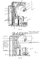
- the figure 15 shows (partially in section) the motor / encoder assembly ensuring the controlled actuation of the slide connection forming the second subassembly 7 ', as well as the return spring forming the safety mechanism of this connection.
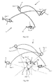
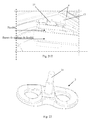
- the robotic installation 1 comprises a robotic device 5 with four degrees of freedom, integrating the first and second subsets 7 and 7 ', such a device making it possible to reach with the probe 2 all the points represented on the figure 10 .
- the robotic installation 1 comprises a redundant robotic device with seven degrees of freedom, integrating the first, second and third subassemblies 7, 7 'and 7 ", the third subassembly 7" consisting of a three-joint mechanism Series 11, 11 ', 11 "forming a spherical wrist.
- Such a robotic device has not only the same properties as the aforementioned first variant (which it integrates), but also makes it possible to achieve a local orientation of the probe 2 with respect to a given reference point PR, for example the point of contact or central point of the contact surface between the probe 2 and the head 3 of the patient 3 '(possibly coinciding with the central point of the probe 2).
- This additional property is particularly necessary in the context of transcranial magnetic stimulation to ensure the tangency condition between the probe 2 and the head 3 during the treatment procedure requiring a controlled scanning movement of said probe.
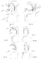
- the third sub-assembly 7 "forming the spherical wrist is essentially constituted by a first hinge 11 formed of a rail 24 in an arc integral with the movable portion 12 of the second subassembly 7 'and on which circulates a carriage 25 whose displacement is controlled by an actuator 26, by a second articulation 11 'formed of two arms 27 rigidly mounted on the movable carriage 25 by one of their ends and carrying at their opposite ends each a fixed carriage 28 cooperating each (curvilinear sliding) with a movable rail portion 29 in the form of a circular arc and parallel to each other, and by a third hinge 11 "in the form of a bearing plate 30, secured to the rails movable 29 and adapted to receive with rotation (about axis 7) a hub 31 integral with the probe 2.
- the actuator 36 (for example an electric motor) ensuring the displacement of the movable rails 29 in the carriages 28 may, for example, be carried by the arms 27, the transmission of the movement being ensured through or around the latter (capstans). .
- the actuator 37 (electric motor) ensuring the rotation of the probe 2 around its hub 31 (axis 7) can be directly carried by the bearing plate 30 receiving the probe 2.
- the maximum angular ranges for the joints 11, 11 'and 11 "forming the third subassembly 7", as well as for the articulations 8, 8' and 8 ", are determined during the design of the robotic device 5 by evaluating (on the basis of a three-dimensional reconstitution of the patient's head from MRI images for example) the angles necessary to ensure the tangency of the front face of the probe 2 at the different regions of the head to be reached.
- the robotic installation 1 essentially comprises a rigid support structure 4 (for example in the form of an assembly of non-magnetic metal profiles), a casing (casing or casing 4 '), an adjustable seat 6, and a robotic device 5 having seven degrees of freedom.
- the robotic device 5 allows the positioning of a probe 2 by displacement around a fixed point PF in space. It allows in particular the positioning of an imaging probe 2 or stimulation around the head 3 of a patient 3 '. Any other device to be kept in safe contact with the head can also be envisaged.
- the robotic device 5 is shown with an effector (probe 2) for carrying out a transcranial magnetic stimulation (SMT) treatment.
- an effector probe 2 for carrying out a transcranial magnetic stimulation (SMT) treatment.
- the robotic device 5 is composed of three subsets 7, 7 'and 7 "connected in series: a main structure 7 with three degrees of freedom, a sliding link 7' actuated and a spherical wrist 7" with three degrees of freedom .
- the main structure 7 allows the placement and displacement of the center of the transcranial magnetic stimulation probe 2 on a sphere centered on the patient 3 '. It is a kinematic plan of a spherical series robot structure ( figure 6 ).
- the actuated slide connection (second subassembly 7 ') allows the displacement of the probe 2 in contact with the patient 3'.
- the actuation direction (axis 4), close to the normal surface of the head 3 of the patient, allows to simply manage the probe / patient contact force: the force control is obtained by servocontrolling this single axis (axis 4).
- the slide connection 7 ' is returned to position by a mechanical device (for example of the prestressed spring type). In case of power failure, the probe 2 tends to move away from the patient ensuring the safety of the latter.
- the spherical wrist (subset 7 "/ Figures 11, 12 and 13 ) makes it possible to impose the condition of tangency of the plane of the probe 2 to the head 3 of the patient, necessitated by the treatment.
- the clean rotation of the probe (axis 7) makes it possible to orient the magnetic field, and to excite as well as possible the cortical furrows.
- the behavior of the robotic device 5 is safe in case of voluntary or involuntary power cut (emergency stop, end of use, power failure): the rotary joint 8 around the axis 1 of rotational movement returns then in a high upright position ( Figure 7A ) by a constant voltage booster system ( Figures 17 and 18 ), avoiding any fall of the device on the patient.
- the return device associated with the slide connection will automatically move the probe from the head 3 of the patient in the event of a similar incident.
- the hinge 8 'providing a displacement in rotation about the axis of the shaft 17 (axis 2) is controlled by means of an electric motor gearing on a perpendicular axis (shaft 17).
- This axis makes it possible to obtain the desired rotation by means of a gearbox, for example a conical pinion meshing with a toothed wheel integral with the shaft 17.
- the latter is also connected to a braking device 23 for lack thereof current. In case of suppression of the latter, the braking and the locking of the rotation is ensured, avoiding any uncontrolled movement around the articulation 8 ', and possible interference with the patient.
- the output of the volume 9 must, however, be possible even in the event of failure of the robotic installation 1. If at this moment the probe 2 is for example located facing the patient 3 ', the annoying in its movement of exit, an operator can intervene manually to punctually send a current into the brake 23 and manually orient the robotic device 5 (in one of the positions of the Figures 8A and 8D ).
- the figure 22 represents a SMT probe of conventional shape at the level of the general constitution and comprising a rear means 31 allowing its rotational mounting in the bearing plate 30 of the spherical wrist forming the third subassembly 7 ".
- the probe comprises an active element 8-shaped copper winding, allowing the creation of an intense magnetic field.
- the proper functioning of the probe 2 requires its cooling, for example by air circulation.
- the creation of the magnetic field at the SMT probe 2 causes the heating of the copper conductor that composes it. To ensure proper operation, cooling must be ensured.
- the movements of the patient 3 ' are detected with the aid of an external locator, making it possible to determine the position and orientation of the patient's head. To ensure the proper functioning of this locator, it is necessary to minimize the presence of cables and hoses around the robotic device 5. The presence of cables could further hamper the patient or the operator during the use of the device.
- the robotic device 5 is designed so as to integrate a hose allowing the cooling of the SMT probe 2 by suction of air from a vacuum cleaner or similar vacuum device integrated in the installation 1, as well as the cable of power supply allowing the operation of the probe.
- a rotating ring-shaped ring is created around the pivot connection that constitutes the hinge 8' (axis 2 / Figures 21A and 21B ).
- This seal consists of a hollow O-piece and a cap pressed against it to seal. Air circulates in the cavity of the O-piece to pass between the two sets in relative motion at the hinge 8 '.
- a winding system is put in place.
- This system is composed of a cylindrical surface located on the rotation shaft 17 providing the axis 2 ( Figure 21C and 21D ), around which the hose is wound, and a pulley urged in rotation on which the cable then travels.
- the cable penetrates inside this pulley to exit at its axis of rotation. As soon as a rotation around the joint causes an elongation of the cable strand, the excess is wound on the pulley automatically.
- the arc length variation ( figure 9 ) is managed, for the air intake, by the use of a compressible hose.
- the variation in length is absorbed by reducing the apparent length of the hose.
- the variation of the length of the power cable is taken into account by the installation of a pulley with return by torsion spring.
- the implementation of the robotic installation 1 according to the invention in the SMT application or a similar application, assumes an initial positioning of the patient 3 'in order to reset the center PF of the spherical main mechanism (first subset 7) With the center of the head 3.
- the seat 6 is thus provided with two adjustment devices 32 and 32 ', in horizontal and vertical directions, each associated with a respective manual control member 32 "(for example a crank).
- the positioning procedure will include manual adjustment facilitated by this continuous adjustment device with two degrees of freedom, and will be based either on the estimation of the position of the head from an external locator or by an optical indication of the center PF.
- Two operative strategies can be envisaged after an initial calibration of the patient's head in the volume 9 with respect to the focal point PF of the first and second subsets 7 and 7 '(projection of a cross on the patient's forehead).
- the patient and in particular the patient's head is held in position after stalling, so as to avoid an offset between the predetermined trajectory of the probe 2 and the areas to be treated.
- the patient is provided with passive markers (for example a marker strip encircling his head or a mask placed on the face) that can be detected by corresponding position sensors (for example). example two infrared or optical cameras at 90 °).
- position sensors for example two infrared or optical cameras at 90 °.
- the information of these sensors is provided continuously to the control and control unit of the robotic installation 1, which will modify the precalculated trajectory of the probe 2 according to the possible movements of the patient, in the manner of a servo in real time motion.
- Such tracking system is tracking, for example, known by the company NDI Inc. under the name POLARIS.
- the various actuators of the rotary joints of the three subassemblies 7, 7 'and 7 "preferably consist of electric motors (for example direct current or harmonic excitation) associated with mechanisms of transmission and / or reduction of the movement and to position sensors and / or encoders, well known in the field of robotics, all of these actuators being driven by a control unit and adapted control, for example a computer unit, also calculating and storing the trajectory of the probe 2, this from data programmed or deduced from previous images.
- electric motors for example direct current or harmonic excitation
- the robotic installation 1 thus makes it possible to satisfy the abovementioned requirements of precision (positioning to within 1 mm) and of safety (active and passive), and to respond to the constraints associated with an automated procedure in a medical environment.
- the present invention also relates to a transcranial magnetic stimulation treatment apparatus, essentially comprising a probe 2 comprising a magnetic stimulation coil and carried by a robotic installation 1.
- This apparatus is characterized in that the robotic installation 1 consists of an installation as described above and illustrated by way of example in the appended figures, and which incorporates a robotic device 5 with seven degrees of freedom, which is capable of producing a automatic positioning and movement of said probe around the head of a patient according to a predetermined path, under the control of a control unit and control.
- Providing a robotic device 5 with seven degrees of freedom, i.e., a redundant degree of freedom, enables satisfactory kinematic behavior and the guarantee of precise displacement and positioning at each joint as well as optimized security at the control level.
- this apparatus also comprises a positioning system, preferably in position and in orientation, of the head 3 of the patient 3 'in the volume 9 receiving the patient, cooperating with the control and control unit in order to achieve a calibration of the head 3 with respect to the focal point PF of the first subassembly 7 of the robotic device 5 and a servo-control, according to the movements of the head 3, of the position of the probe 2 via the robotic installation 1, under the control of the control and steering unit and according to the signals or data provided by the location system.
- a positioning system preferably in position and in orientation, of the head 3 of the patient 3 'in the volume 9 receiving the patient, cooperating with the control and control unit in order to achieve a calibration of the head 3 with respect to the focal point PF of the first subassembly 7 of the robotic device 5 and a servo-control, according to the movements of the head 3, of the position of the probe 2 via the robotic installation 1, under the control of the control and steering unit and according to the signals or data provided by the location system.
- Such a device allows the operator to be replaced during an SMT procedure, ensuring the accuracy and security required.
- the invention can be used in the context of a transcranial magnetic stimulation method using the apparatus described above.
- the trajectory of the center of the coil of the probe 2 is calculated, as well as the orientation of said probe during the trajectory, for an optimal stimulation of said regions, this on the basis of a three-dimensional reconstruction of the patient's head.
- the speed of movement of the probe as well as the power, the frequency and the number of stimulation sequences per region to be stimulated are calculated or programmed.
- Calculation of the required trajectory which also takes into account the physical and mechanical constraints of the robotic device (angular limits of articulation rotation, limits in terms of speed of rotation of the joints, collision avoidance), can for example be realized at the level of the command and control unit by means of a probabilistic motion planning algorithm, for example based on an algorithm using samples and derived from " Kavraki L. et al., IEE Transaction on Robotics and Automation, 1996, Volume 12, pages 566-580 .
- a pseudo-inverse velocity control technique is used to move the probe 2 (see for example: " Advanced robotics: Redundancy and Optimization, Nakamura Y., Addison-Wesley Longman Publishing, Boston, 1991 ).
Landscapes
- Health & Medical Sciences (AREA)
- Life Sciences & Earth Sciences (AREA)
- Engineering & Computer Science (AREA)
- Surgery (AREA)
- Medical Informatics (AREA)
- Veterinary Medicine (AREA)
- Nuclear Medicine, Radiotherapy & Molecular Imaging (AREA)
- Public Health (AREA)
- General Health & Medical Sciences (AREA)
- Animal Behavior & Ethology (AREA)
- Biomedical Technology (AREA)
- Heart & Thoracic Surgery (AREA)
- Molecular Biology (AREA)
- Robotics (AREA)
- High Energy & Nuclear Physics (AREA)
- Radiology & Medical Imaging (AREA)
- Pathology (AREA)
- Optics & Photonics (AREA)
- Physics & Mathematics (AREA)
- Biophysics (AREA)
- Manipulator (AREA)
- Magnetic Treatment Devices (AREA)
Claims (14)
- Robotergesteuerte Einrichtung (1) zur gelenkten und kontrollierten Positionierung und Bewegung einer Sonde zur transkraniellen Magnetstimulation im Bereich des oder um den Kopf (3) eines Patienten (3'),
wobei die genannte Einrichtung (1), im Wesentlichen eine Tragstruktur (4) umfassend, auf der die Komponenten einer Robotervorrichtung (5) angebracht sind, die eine offene kinematische Kette bilden, an ihrem freien Ende die genannte Sonde (2) in kontrollierter Stellung trägt, wobei eine einstellbare Vorrichtung (6) zum Tragen und Halten des Patienten (3') im Wesentlichen in Sitzstellung Teil der genannten Tragstruktur oder mit ihr verbunden ist,
wobei die genannte Robotervorrichtung (5) zwei kinematische Untereinheiten (7, 7') aufweist, die miteinander in Reihe verbunden sind, nämlich einerseits eine erste Untereinheit (7) in Form eines Mechanismus mit Drehgelenken (8, 8', 8"), die mit der Tragstruktur (4) über ein erstes Gelenk (8) verbunden ist und einer kugelförmigen, offenen kinematischen Anordnung mit drei Freiheitsgraden entspricht, wobei sich alle Gelenkelemente (8, 8', 8") außerhalb des Volumens (9) befinden, das gegebenenfalls den Patienten (3') empfängt, und ihre Drehachsen (Axe 1, Axe 2 und Axe 3) in einem Brennpunkt (PF) konvergieren, der im Wesentlichen dem hypothetischen Zentrum des Kopfes (3) des Patienten (3') in Behandlungsstellung entspricht, und andererseits eine zweite Untereinheit (7') in Form eines Mechanismus zur linearen Verschiebung längs einer Achse (Axe 4), die durch den genannten Brennpunkt (PF) verläuft und mit dem beweglichen Teil (10) des dritten Gelenks (8") in Reihe der ersten Untereinheit (7) verbunden ist,
Einrichtung (1), dadurch gekennzeichnet, dass die Robotervorrichtung (5) außerdem eine dritte Untereinheit (7") in Form eines zweiten Mechanismus mit drei Drehgelenken in Reihe (11, 11', 11") umfasst, die ein kugelförmiges Handgelenk mit drei Freiheitsgraden bildet, wobei diese dritte Untereinheit (7") am beweglichen Teil (12) der zweiten Untereinheit (7') befestigt ist, womit also die Robotervorrichtung (5) mit sieben Freiheitsgraden redundant ist. - Einrichtung nach Patentanspruch 1, dadurch gekennzeichnet, dass das erste Drehgelenk (8) der ersten Untereinheit (7) aus einer Verbindung mit kreisförmiger Gleitschiene besteht, eine Führungsschiene (13), vorzugsweise eine Zwillingsschiene in Kreisbogenform, im Wesentlichen halbkreisförmig, umfassend, die an der Tragstruktur (4) befestigt ist, und einen beweglichen Wagen (14), der in der Lage ist, auf der genannten Schiene (13) zu laufen, und dessen Bewegung durch ein Übertragungsgestänge (15) veranlasst wird, das mit einem Wirkglied (16) verbunden ist, wobei die Kreisbewegung in der Mittelebene des Patienten (3) in Behandlungsstellung erfolgt und die genannte Führungsschiene (13) eine Stellung und Ausdehnung hat, derart dass sie sich um den Kopf (3) des genannten Patienten (3') im Wesentlichen von der hinteren Schädelbasis bis zur Stirn erstreckt.
- Einrichtung nach Patentanspruch 2, dadurch gekennzeichnet, dass das zweite Drehgelenk (8') der ersten Untereinheit (7) aus einem Achsengelenk mit einer Welle (17) besteht, die drehbar in einem Lager (18) montiert ist, das im beweglichen Wagen (14) ausgebildet ist, der Teil des ersten Drehgelenks (8) ist, wobei die Drehung der genannten Welle durch ein Wirkglied (19) veranlasst wird, beispielsweise eine Einheit aus Motor und Getriebe, das vom genannten Wagen (14) getragen wird.
- Einrichtung nach irgendeinem der Patentansprüche 1 bis 3, dadurch gekennzeichnet, dass das dritte Drehgelenk (8") der ersten Untereinheit (7) aus einer Verbindung mit kreisförmiger Gleitschiene in Form von zwei Schienen (20, 21), die gleitend zusammenwirken und jeweils kreisbogenförmig ausgebildet sind, besteht, wobei die genannten Schienen (20 und 21) relativ zueinander zwischen einer eingezogenen Anordnung, in der sie im Wesentlichen übereinander liegen oder sich auf ihrer ganzen Länge überlappen, und einer ausgezogenen Stellung, in der sie nur noch in einem geringen Teil übereinander liegen, verschoben werden können.
- Einrichtung nach den Patentansprüchen 3 und 4, dadurch gekennzeichnet, dass eine (20) der Schienen (20, 21), die das dritte Drehgelenk (8") bilden, starr mit der Welle (17) des zweiten Drehgelenks (8') verbunden ist, wobei die beiden Schienen (20 und 21) in ihrer Stellung relativ zueinander konstruktiv, durch mechanische Verbindung oder durch Blockierung des Wirkgliedes, das ihre Relativbewegung zueinander sicherstellt, blockiert werden können.
- Einrichtung nach irgendeinem der Patentansprüche 2, 3 und 5, dadurch gekennzeichnet, dass der bewegliche Wagen (14) des ersten Drehgelenks (8) durch einen Rückstellmechanismus konstanter Spannung (22), beispielsweise mit einem Drahtseil (22'), permanent in die äußerste obere Stellung vorgespannt wird.
- Einrichtung nach irgendeinem der Patentansprüche 3 und 5, dadurch gekennzeichnet, dass eine Vorrichtung (23) zur Blockierung der Drehung der Welle (17) mit dem Wirkglied (19) verbunden ist, beispielsweise in Form einer Bremse, beispielsweise vom elektromagnetischen Typ, die bei Abwesenheit der Versorgung mit elektrischem Strom in dessen Bereich tätig ist, wobei die genannte Vorrichtung (23) von einem Bediener mit Hilfe einer manuellen Betätigung der Stromversorgung freigesetzt werden kann, um eine freie Drehung der Welle (17) um ihre Drehachse (Axe 2) zu erlauben.
- Einrichtung nach irgendeinem der Patentansprüche 4 und 5, dadurch gekennzeichnet, dass das Wirkglied des dritten Drehgelenks (8") der ersten Untereinheit (7) eine Blockierung der beiden Schienen (20 und 21) in ihrer Stellung zueinander bei Abwesenheit der Versorgung mit elektrischem Strom vornimmt.
- Einrichtung nach irgendeinem der Patentansprüche 1 bis 8, dadurch gekennzeichnet, dass ein Belastungssensor, insbesondere ein Drucksensor, mit der zweiten Untereinheit (7') verbunden ist, der eine Regulierung der Kraft der genannten zweiten Untereinheit (7') in der Verschiebungsrichtung (Axe 4), im Wesentlichen senkrecht zum Kopf (3) des Patienten (3') in der Behandlungsstellung, erlaubt, wobei diese Untereinheit (7') außerdem einen Rückstellmechanismus beispielsweise mechanischer Art umfasst, der die Sonde (2) in einen Abstand von der Oberfläche des Kopfes (3) des Patienten (3') vorspannt.
- Einrichtung nach Patentanspruch 1, dadurch gekennzeichnet, dass die Drehachsen (Axe 5, Axe 6, Axe 7) der Drehgelenke (11, 11', 11 ") der dritten Untereinheit (7") konvergieren.
- Einrichtung nach irgendeinem der Patentansprüche 1 bis 10, dadurch gekennzeichnet, dass die dritte Untereinheit (7"), die ein kugelförmiges Handgelenk bildet, im Wesentlichen aus einem ersten Gelenk (11) besteht, das aus einer kreisbogenförmigen Schiene (24) besteht, die am beweglichen Teil (12) der zweiten Untereinheit (7') befestigt ist und auf der ein Wagen (25) läuft, dessen Verschiebung von einem Wirkglied (26) veranlasst wird, aus einem zweiten Gelenk (11'), das aus zwei Armen (27) besteht, die mit einem ihrer Enden starr am beweglichen Wagen (25) angebracht sind und an ihrem entgegengesetzten Ende jeweils einen feststehenden Wagen (28) tragen, der jeweils mit einem Teil der kreisbogenförmigen beweglichen Schiene (29) zusammenwirkt, und die zueinander parallel sind, und aus einem dritten Gelenk (11") in Form einer Halteplatte mit Lager (30), die an den beweglichen Schienen (29) befestigt und in der Lage ist, drehbar (Axe 7) eine Nabe (31) aufzunehmen, die an der Sonde (2) befestigt ist.
- Einrichtung nach irgendeinem der Patentansprüche 1 bis 8, 10 und 11, dadurch gekennzeichnet, dass ein Belastungssensor, insbesondere ein Drucksensor, in die Sonde (2) eingebaut ist, die von einer Robotervorrichtung (5) getragen wird, wobei der genannte Belastungssensor Teil einer Reguliervorrichtung der Kraft der zweiten Untereinheit (7') ist.
- Gerät zur Behandlung durch transkranielle Magnetstimulation, im Wesentlichen eine Sonde umfassend, die eine Spule zur Magnetstimulation umfasst und von einer robotergesteuerten Einrichtung getragen wird, Gerät, dadurch gekennzeichnet, dass die robotergesteuerte Einrichtung (1) aus einer Einrichtung nach irgendeinem der Patentansprüche 1 bis 12 besteht, die eine Robotervorrichtung (5) mit sieben Freiheitsgraden umfasst, die unter der Kontrolle einer Steuer- und Lenkeinheit in der Lage ist, eine automatische Positionierung und Bewegung der genannten Sonde (2) um den Kopf (3) eines Patienten (3') auf einer vorher festgelegten Bahn vorzunehmen.
- Gerät nach Patentanspruch 13, dadurch gekennzeichnet, dass es auch ein System zur Lokalisierung, vorzugsweise der Stelle und der Orientierung, des Kopfes (3) des Patienten (3') im Volumen (9), das den Patienten empfängt, umfasst, das mit der Steuer- und Lenkeinheit zusammenarbeitet, um eine Feststellung des Kopfes (3) relativ zum Brennpunkt (PF) der ersten Untereinheit (7) der Robotervorrichtung (5) vorzunehmen und in Abhängigkeit von den Bewegungen des Kopfes (3) eine Regelung der Stellung der Sonde (2) durch eine robotergesteuerte Einrichtung (1) unter Kontrolle der Steuer- und Lenkeinheit und in Abhängigkeit von den Signalen oder Daten, die das Lokalisierungssystem ausgibt.
Applications Claiming Priority (2)
| Application Number | Priority Date | Filing Date | Title |
|---|---|---|---|
| US81634306P | 2006-06-26 | 2006-06-26 | |
| PCT/FR2007/051518 WO2008001003A2 (fr) | 2006-06-26 | 2007-06-26 | Installation robotisee pour le positionnement et le deplacement d'un organe ou instrument et appareil de traitement comprenant une telle installation |
Publications (2)
| Publication Number | Publication Date |
|---|---|
| EP2032066A2 EP2032066A2 (de) | 2009-03-11 |
| EP2032066B1 true EP2032066B1 (de) | 2016-08-24 |
Family
ID=38846013
Family Applications (1)
| Application Number | Title | Priority Date | Filing Date |
|---|---|---|---|
| EP07803940.1A Active EP2032066B1 (de) | 2006-06-26 | 2007-06-26 | Robotergesteuerte positionierungs- und bewegungseinrichtung für ein organ oder instrument und behandlungseinrichtung enthaltend eine solche einrichtung |
Country Status (5)
| Country | Link |
|---|---|
| US (1) | US8303478B2 (de) |
| EP (1) | EP2032066B1 (de) |
| JP (1) | JP2009540999A (de) |
| CA (1) | CA2655433C (de) |
| WO (1) | WO2008001003A2 (de) |
Families Citing this family (45)
| Publication number | Priority date | Publication date | Assignee | Title |
|---|---|---|---|---|
| GB2454017A (en) * | 2007-10-26 | 2009-04-29 | Prosurgics Ltd | A control assembly |
| GB0804633D0 (en) | 2008-03-12 | 2008-04-16 | Prosurgics Ltd | a telescopic support |
| DE102008022921A1 (de) * | 2008-05-09 | 2009-11-12 | Siemens Aktiengesellschaft | Anordnung und Verfahren zur Positionierung von Geräten |
| EP2444119B1 (de) | 2009-06-15 | 2016-09-21 | Osaka University | Magnetstimulator |
| EP2517752B1 (de) * | 2009-12-25 | 2017-10-18 | IHI Corporation | Magnetkörper und vorrichtung zur steuerung der wirkstofffreisetzung unter verwendung des magnetkörpers |
| FR2974322B1 (fr) * | 2011-04-22 | 2013-05-31 | Gemon Jean Pierre | Robot d'usinage |
| WO2013062021A1 (ja) * | 2011-10-24 | 2013-05-02 | 帝人ファーマ株式会社 | 経頭蓋磁気刺激システム |
| GB2498943A (en) * | 2012-01-31 | 2013-08-07 | Ibm | Evaluating and optimizing a trajectory function |
| CN111513852B (zh) * | 2012-06-01 | 2023-11-03 | 直观外科手术操作公司 | 硬件受限的远程中心机器人操纵器的冗余轴线和自由度 |
| KR101310530B1 (ko) | 2012-07-18 | 2013-10-14 | 한국 한의학 연구원 | 맥 측정 장치 및 그의 맥 측정 방법 |
| ITUD20120161A1 (it) * | 2012-09-20 | 2014-03-21 | Asa S R L | Apparecchiatura per emettere radiazioni terapeutiche |
| US10188868B2 (en) | 2013-11-29 | 2019-01-29 | Nexstim Oyj | Device support apparatus |
| ES2768426T3 (es) * | 2013-11-29 | 2020-06-22 | Nexstim Oyj | Aparato de soporte de un dispositivo |
| WO2016022347A1 (en) * | 2014-08-04 | 2016-02-11 | Brachium, Inc. | A medical robotic works station |
| WO2016056326A1 (ja) * | 2014-10-07 | 2016-04-14 | 帝人ファーマ株式会社 | 経頭蓋磁気刺激システム |
| US10413744B2 (en) | 2014-10-07 | 2019-09-17 | Teijin Pharma Limited | Transcranial magnetic stimulation system |
| CN104436443B (zh) * | 2014-11-20 | 2017-02-22 | 西安索立德医疗科技有限公司 | 一种脑皮质经颅磁刺激三维定位导航系统及导航方法 |
| CN104474636B (zh) * | 2014-11-20 | 2017-02-22 | 西安索立德医疗科技有限公司 | 一种多点多频三维经颅磁刺激系统及颅内外坐标转换方法 |
| KR101622539B1 (ko) * | 2015-01-21 | 2016-05-19 | 삼성전자 주식회사 | 브레이크 장치 및 이를 포함하는 의료기기 |
| KR101670735B1 (ko) * | 2015-02-27 | 2016-10-31 | 한국과학기술연구원 | 운동 플랫폼의 위치를 제어하는 로봇 및 이를 구비한 생체 자극 시스템 |
| EP3316831B1 (de) * | 2015-07-03 | 2023-06-07 | Ophthorobotics AG | Intraokulares injektionssystem und verfahren zur steuerung solch eines systems |
| AT517737B1 (de) * | 2015-10-02 | 2018-07-15 | Pontemed Ag | Magnetische Stimulationsvorrichtung |
| US10874871B2 (en) * | 2015-11-09 | 2020-12-29 | Axilum Robotics (Societe Par Actions Simpl | Magnetic stimulation device comprising a force-sensing resistor |
| CA3020256A1 (en) * | 2016-04-06 | 2017-10-12 | Teijin Pharma Limited | Transcranial magnetic stimulation system and positioning assistance method and program |
| US11247039B2 (en) | 2016-05-03 | 2022-02-15 | Btl Healthcare Technologies A.S. | Device including RF source of energy and vacuum system |
| US10434322B2 (en) | 2016-05-17 | 2019-10-08 | Center Of Human-Centered Interaction For Coexistence | Robot for controlling position of motion platform and bio-stimulation system having the same |
| US10583287B2 (en) | 2016-05-23 | 2020-03-10 | Btl Medical Technologies S.R.O. | Systems and methods for tissue treatment |
| US10556122B1 (en) | 2016-07-01 | 2020-02-11 | Btl Medical Technologies S.R.O. | Aesthetic method of biological structure treatment by magnetic field |
| JP7005608B2 (ja) * | 2016-10-04 | 2022-02-04 | インテュイティブ サージカル オペレーションズ, インコーポレイテッド | コンピュータ支援遠隔操作手術システムおよび方法 |
| US11039799B2 (en) * | 2017-03-09 | 2021-06-22 | Carestream Health, Inc. | Bearing system for cone beam computed tomography |
| CN108042208B (zh) * | 2017-11-15 | 2024-05-03 | 重庆金山医疗机器人有限公司 | 微创手术机器人主动臂 |
| IT201800000689A1 (it) * | 2018-01-10 | 2019-07-10 | Tecres Spa | Struttura di supporto per un dispositivo chirurgico e relativo metodo di posizionamento |
| CN108161485B (zh) * | 2018-02-08 | 2024-01-23 | 北部湾大学 | 教学型五轴数控机床 |
| CN108670411B (zh) * | 2018-06-04 | 2019-08-02 | 哈尔滨工业大学 | 一种利用双倍行程弧形滑轨的空间远心点运动机构 |
| CN109224301B (zh) * | 2018-11-05 | 2023-09-01 | 长春大学 | 具有精确定位及自动跟踪功能的经颅磁刺激装置及方法 |
| JP7129963B2 (ja) * | 2019-09-30 | 2022-09-02 | 富士フイルム株式会社 | 放射線撮影装置 |
| US11878167B2 (en) | 2020-05-04 | 2024-01-23 | Btl Healthcare Technologies A.S. | Device and method for unattended treatment of a patient |
| KR20230000081U (ko) | 2020-05-04 | 2023-01-10 | 비티엘 헬쓰케어 테크놀로지스 에이.에스. | 환자의 무인 치료를 위한 디바이스 및 방법 |
| CN111728715A (zh) * | 2020-06-08 | 2020-10-02 | 南京伟思医疗科技股份有限公司 | 一种支架自动跟随机构 |
| CA3183762A1 (en) * | 2020-06-25 | 2021-12-30 | Roch M. Comeau | Articulated positioning system for a scientific or medical tool, robotized positioning assembly comprising same and corresponding method |
| CN111956960B (zh) * | 2020-08-19 | 2022-05-24 | 北京石油化工学院 | 一种高强度聚焦超声治疗系统动态定位装置 |
| CN112546447B (zh) * | 2020-11-24 | 2021-07-27 | 四川君健万峰医疗器械有限责任公司 | 一种刺激线圈定位装置 |
| US11896816B2 (en) | 2021-11-03 | 2024-02-13 | Btl Healthcare Technologies A.S. | Device and method for unattended treatment of a patient |
| CN115089304B (zh) * | 2022-06-28 | 2024-03-26 | 吉林大学 | 一种多臂多自由度式微创手术平台 |
| CN116392158B (zh) * | 2023-06-09 | 2023-08-22 | 北京唯迈医疗设备有限公司 | 一种实物体模式dsa控制与反馈装置 |
Family Cites Families (12)
| Publication number | Priority date | Publication date | Assignee | Title |
|---|---|---|---|---|
| US5417210A (en) * | 1992-05-27 | 1995-05-23 | International Business Machines Corporation | System and method for augmentation of endoscopic surgery |
| WO2000028882A2 (en) * | 1998-11-18 | 2000-05-25 | Microdexterity Systems, Inc. | Medical manipulator for use with an imaging device |
| JP4398528B2 (ja) * | 1999-02-12 | 2010-01-13 | 株式会社東芝 | 放射線診断装置 |
| DE19926977A1 (de) | 1999-06-14 | 2001-01-04 | Siemens Ag | Röntgengerät |
| US6590953B2 (en) * | 2000-09-12 | 2003-07-08 | Hitachi Medical Corporation | X-ray CT scanner |
| EP1269913B1 (de) * | 2001-06-28 | 2004-08-04 | BrainLAB AG | Vorrichtung für transcraniale magnetische Stimulation und kortikale Kartographie |
| AU2003241457A1 (en) | 2002-05-17 | 2003-12-02 | Musc Foundation For Research Development | Method, apparatus, and system for automatically positioning a probe or sensor |
| DE10242542A1 (de) * | 2002-09-13 | 2004-04-01 | Forschungszentrum Karlsruhe Gmbh | Positioniersystem für die navigierte transkranielle Magnetstimulation |
| US7313430B2 (en) * | 2003-08-28 | 2007-12-25 | Medtronic Navigation, Inc. | Method and apparatus for performing stereotactic surgery |
| US7520848B2 (en) | 2004-04-09 | 2009-04-21 | The Board Of Trustees Of The Leland Stanford Junior University | Robotic apparatus for targeting and producing deep, focused transcranial magnetic stimulation |
| US8177702B2 (en) * | 2004-04-15 | 2012-05-15 | Neuronetics, Inc. | Method and apparatus for determining the proximity of a TMS coil to a subject's head |
| US8088058B2 (en) * | 2005-01-20 | 2012-01-03 | Neuronetics, Inc. | Articulating arm |
-
2007
- 2007-06-26 WO PCT/FR2007/051518 patent/WO2008001003A2/fr active Application Filing
- 2007-06-26 CA CA2655433A patent/CA2655433C/fr active Active
- 2007-06-26 JP JP2009517348A patent/JP2009540999A/ja not_active Withdrawn
- 2007-06-26 US US12/306,806 patent/US8303478B2/en active Active
- 2007-06-26 EP EP07803940.1A patent/EP2032066B1/de active Active
Also Published As
| Publication number | Publication date |
|---|---|
| CA2655433C (fr) | 2014-11-18 |
| WO2008001003A3 (fr) | 2008-06-19 |
| WO2008001003A2 (fr) | 2008-01-03 |
| US8303478B2 (en) | 2012-11-06 |
| US20090216067A1 (en) | 2009-08-27 |
| JP2009540999A (ja) | 2009-11-26 |
| CA2655433A1 (fr) | 2008-01-03 |
| EP2032066A2 (de) | 2009-03-11 |
Similar Documents
| Publication | Publication Date | Title |
|---|---|---|
| EP2032066B1 (de) | Robotergesteuerte positionierungs- und bewegungseinrichtung für ein organ oder instrument und behandlungseinrichtung enthaltend eine solche einrichtung | |
| EP2376012B1 (de) | Vorrichtung zur lagerung eines patienten relativ zu einer strahlung | |
| CA2944975C (fr) | Refracteur et procede de mesure de refraction utilisant un tel refracteur | |
| EP2042076B1 (de) | Schwenkbare, bewegliche Struktur vom Typ Katheter oder Endoskop | |
| FR2945724A1 (fr) | Appareil a rayons x | |
| US8540701B2 (en) | Hair treatment system | |
| FR2972915A1 (fr) | Systeme d'imagerie medicale multiplan | |
| EP2822446B1 (de) | Motorisierte und modulare instrumentenvorrichtung und endoskopiesystem mit einer solchen vorrichtung | |
| EP3154466A2 (de) | Robotisiertes modul zur führung einer langgestreckten flexiblen medizinischen vorrichtung | |
| US8529560B2 (en) | Hair treatment system | |
| CA2734418A1 (fr) | Outil electroportatif muni d'un dispositif permettant de determiner la position relative entre deux organes dudit outil dont l'un au moins est mobile | |
| FR3037840A1 (fr) | Bras articule motorise a cabestan a cable comprenant un frein. | |
| EP2303098A1 (de) | Vorrichtung zur kontrollierten translationsverschiebung eines länglichen elements | |
| CA2087348C (fr) | Dispositif de support et de positionnement d'un microscope | |
| EP2726258B1 (de) | Robotersystem zum verschieben eines ferngesteuerten werkzeugs | |
| EP2512346B1 (de) | Zahnröntgengerät mit zephalometrischer bildgebung und zugehöriges verfahren | |
| FR3037249A1 (fr) | Procede robotise d'entrainement de catheter et de guide de catheter | |
| US20070005047A1 (en) | Hair modification using converging light | |
| EP0265470B1 (de) | Instrument zur systematischen behandlung, zum beispiel in der dermatologie, besonders mit laserenergie | |
| EP2124709B1 (de) | Flexible endoskopvorrichtung mit visueller kontrolle | |
| FR2982759A1 (fr) | Appareil de radiologie dentaire panoramique | |
| EP2377466B1 (de) | Gerät zur Behandlung durch Druckwellen, das mit einem System zum Verschieben des Bogens eines Bildgebungssystems durch Röntgenwellen ausgestattet ist | |
| FR2648383A1 (fr) | Systeme local de decoupe par faisceau laser | |
| WO2022003154A1 (fr) | Dispositif robotique pour le guidage d'un bras robotise | |
| FR2875282A1 (fr) | Transmission mecanique axialement orientable et rigide en torsion |
Legal Events
| Date | Code | Title | Description |
|---|---|---|---|
| PUAI | Public reference made under article 153(3) epc to a published international application that has entered the european phase |
Free format text: ORIGINAL CODE: 0009012 |
|
| 17P | Request for examination filed |
Effective date: 20081219 |
|
| AK | Designated contracting states |
Kind code of ref document: A2 Designated state(s): AT BE BG CH CY CZ DE DK EE ES FI FR GB GR HU IE IS IT LI LT LU LV MC MT NL PL PT RO SE SI SK TR |
|
| AX | Request for extension of the european patent |
Extension state: AL BA HR MK RS |
|
| RIN1 | Information on inventor provided before grant (corrected) |
Inventor name: LAROCHE, EDOUARD Inventor name: BAYLE, BERNARD Inventor name: RENAUD, PIERRE Inventor name: LEBOSSE, CYRILLE Inventor name: PICCIN, OLIVIER Inventor name: DE MATHELIN, MICHEL |
|
| DAX | Request for extension of the european patent (deleted) | ||
| RAP1 | Party data changed (applicant data changed or rights of an application transferred) |
Owner name: UNIVERSITE DE STRASBOURG (ETABLISSEMENT PUBLIC NAT Owner name: INSTITUT NATIONAL DES SCIENCES APPLIQUEES (ETABLIS Owner name: CENTRE NATIONAL DE LA RECHERCHE SCIENTIFIQUE (CNRS |
|
| 111L | Licence recorded |
Designated state(s): AT BE BG CH CY CZ DE DK EE ES FI FR GB GR HU IE IS IT LT LU LV MC MT NL PL PT RO SE SI SK TR Free format text: EXCLUSIVE LICENSE Name of requester: AXILUM ROBOTICS SAS, FR Effective date: 20140408 |
|
| 17Q | First examination report despatched |
Effective date: 20141010 |
|
| REG | Reference to a national code |
Ref country code: DE Ref legal event code: R079 Ref document number: 602007047625 Country of ref document: DE Free format text: PREVIOUS MAIN CLASS: A61B0019000000 Ipc: A61N0002000000 |
|
| GRAP | Despatch of communication of intention to grant a patent |
Free format text: ORIGINAL CODE: EPIDOSNIGR1 |
|
| RIC1 | Information provided on ipc code assigned before grant |
Ipc: A61N 5/01 20060101ALI20160308BHEP Ipc: A61B 90/11 20160101ALI20160308BHEP Ipc: A61B 34/35 20160101ALI20160308BHEP Ipc: A61B 90/50 20160101ALI20160308BHEP Ipc: A61N 2/00 20060101AFI20160308BHEP |
|
| INTG | Intention to grant announced |
Effective date: 20160321 |
|
| RIN1 | Information on inventor provided before grant (corrected) |
Inventor name: LEBOSSE, CYRILLE Inventor name: LAROCHE, EDOUARD Inventor name: PICCIN, OLIVIER Inventor name: BAYLE, BERNARD Inventor name: RENAUD, PIERRE Inventor name: DE MATHELIN, MICHEL |
|
| GRAS | Grant fee paid |
Free format text: ORIGINAL CODE: EPIDOSNIGR3 |
|
| GRAA | (expected) grant |
Free format text: ORIGINAL CODE: 0009210 |
|
| 111L | Licence recorded |
Designated state(s): AT BE BG CH CY CZ DE DK EE ES FI FR GB GR HU IE IS IT LT LU LV MC MT NL PL PT RO SE SI SK TR Free format text: EXCLUSIVE LICENSE Name of requester: AXILUM ROBOTICS SAS, FR Effective date: 20140408 |
|
| AK | Designated contracting states |
Kind code of ref document: B1 Designated state(s): AT BE BG CH CY CZ DE DK EE ES FI FR GB GR HU IE IS IT LI LT LU LV MC MT NL PL PT RO SE SI SK TR |
|
| REG | Reference to a national code |
Ref country code: GB Ref legal event code: FG4D Free format text: NOT ENGLISH |
|
| REG | Reference to a national code |
Ref country code: CH Ref legal event code: EP Ref country code: CH Ref legal event code: PK Free format text: COMPLETEMENT D'ENREGISTREMENT DE LICENCE: LICENCE EXCLUSIVE |
|
| REG | Reference to a national code |
Ref country code: AT Ref legal event code: REF Ref document number: 822535 Country of ref document: AT Kind code of ref document: T Effective date: 20160915 |
|
| REG | Reference to a national code |
Ref country code: IE Ref legal event code: FG4D Free format text: LANGUAGE OF EP DOCUMENT: FRENCH |
|
| REG | Reference to a national code |
Ref country code: DE Ref legal event code: R096 Ref document number: 602007047625 Country of ref document: DE |
|
| REG | Reference to a national code |
Ref country code: LT Ref legal event code: MG4D |
|
| REG | Reference to a national code |
Ref country code: NL Ref legal event code: MP Effective date: 20160824 |
|
| REG | Reference to a national code |
Ref country code: AT Ref legal event code: MK05 Ref document number: 822535 Country of ref document: AT Kind code of ref document: T Effective date: 20160824 |
|
| PG25 | Lapsed in a contracting state [announced via postgrant information from national office to epo] |
Ref country code: IT Free format text: LAPSE BECAUSE OF FAILURE TO SUBMIT A TRANSLATION OF THE DESCRIPTION OR TO PAY THE FEE WITHIN THE PRESCRIBED TIME-LIMIT Effective date: 20160824 Ref country code: NL Free format text: LAPSE BECAUSE OF FAILURE TO SUBMIT A TRANSLATION OF THE DESCRIPTION OR TO PAY THE FEE WITHIN THE PRESCRIBED TIME-LIMIT Effective date: 20160824 Ref country code: LT Free format text: LAPSE BECAUSE OF FAILURE TO SUBMIT A TRANSLATION OF THE DESCRIPTION OR TO PAY THE FEE WITHIN THE PRESCRIBED TIME-LIMIT Effective date: 20160824 Ref country code: FI Free format text: LAPSE BECAUSE OF FAILURE TO SUBMIT A TRANSLATION OF THE DESCRIPTION OR TO PAY THE FEE WITHIN THE PRESCRIBED TIME-LIMIT Effective date: 20160824 |
|
| PG25 | Lapsed in a contracting state [announced via postgrant information from national office to epo] |
Ref country code: LV Free format text: LAPSE BECAUSE OF FAILURE TO SUBMIT A TRANSLATION OF THE DESCRIPTION OR TO PAY THE FEE WITHIN THE PRESCRIBED TIME-LIMIT Effective date: 20160824 Ref country code: PT Free format text: LAPSE BECAUSE OF FAILURE TO SUBMIT A TRANSLATION OF THE DESCRIPTION OR TO PAY THE FEE WITHIN THE PRESCRIBED TIME-LIMIT Effective date: 20161226 Ref country code: AT Free format text: LAPSE BECAUSE OF FAILURE TO SUBMIT A TRANSLATION OF THE DESCRIPTION OR TO PAY THE FEE WITHIN THE PRESCRIBED TIME-LIMIT Effective date: 20160824 Ref country code: ES Free format text: LAPSE BECAUSE OF FAILURE TO SUBMIT A TRANSLATION OF THE DESCRIPTION OR TO PAY THE FEE WITHIN THE PRESCRIBED TIME-LIMIT Effective date: 20160824 Ref country code: SE Free format text: LAPSE BECAUSE OF FAILURE TO SUBMIT A TRANSLATION OF THE DESCRIPTION OR TO PAY THE FEE WITHIN THE PRESCRIBED TIME-LIMIT Effective date: 20160824 Ref country code: GR Free format text: LAPSE BECAUSE OF FAILURE TO SUBMIT A TRANSLATION OF THE DESCRIPTION OR TO PAY THE FEE WITHIN THE PRESCRIBED TIME-LIMIT Effective date: 20161125 |
|
| PG25 | Lapsed in a contracting state [announced via postgrant information from national office to epo] |
Ref country code: EE Free format text: LAPSE BECAUSE OF FAILURE TO SUBMIT A TRANSLATION OF THE DESCRIPTION OR TO PAY THE FEE WITHIN THE PRESCRIBED TIME-LIMIT Effective date: 20160824 Ref country code: RO Free format text: LAPSE BECAUSE OF FAILURE TO SUBMIT A TRANSLATION OF THE DESCRIPTION OR TO PAY THE FEE WITHIN THE PRESCRIBED TIME-LIMIT Effective date: 20160824 |
|
| REG | Reference to a national code |
Ref country code: FR Ref legal event code: PLFP Year of fee payment: 11 |
|
| REG | Reference to a national code |
Ref country code: DE Ref legal event code: R097 Ref document number: 602007047625 Country of ref document: DE |
|
| PG25 | Lapsed in a contracting state [announced via postgrant information from national office to epo] |
Ref country code: BG Free format text: LAPSE BECAUSE OF FAILURE TO SUBMIT A TRANSLATION OF THE DESCRIPTION OR TO PAY THE FEE WITHIN THE PRESCRIBED TIME-LIMIT Effective date: 20161124 Ref country code: CZ Free format text: LAPSE BECAUSE OF FAILURE TO SUBMIT A TRANSLATION OF THE DESCRIPTION OR TO PAY THE FEE WITHIN THE PRESCRIBED TIME-LIMIT Effective date: 20160824 Ref country code: PL Free format text: LAPSE BECAUSE OF FAILURE TO SUBMIT A TRANSLATION OF THE DESCRIPTION OR TO PAY THE FEE WITHIN THE PRESCRIBED TIME-LIMIT Effective date: 20160824 Ref country code: DK Free format text: LAPSE BECAUSE OF FAILURE TO SUBMIT A TRANSLATION OF THE DESCRIPTION OR TO PAY THE FEE WITHIN THE PRESCRIBED TIME-LIMIT Effective date: 20160824 Ref country code: SK Free format text: LAPSE BECAUSE OF FAILURE TO SUBMIT A TRANSLATION OF THE DESCRIPTION OR TO PAY THE FEE WITHIN THE PRESCRIBED TIME-LIMIT Effective date: 20160824 |
|
| PLBE | No opposition filed within time limit |
Free format text: ORIGINAL CODE: 0009261 |
|
| STAA | Information on the status of an ep patent application or granted ep patent |
Free format text: STATUS: NO OPPOSITION FILED WITHIN TIME LIMIT |
|
| 26N | No opposition filed |
Effective date: 20170526 |
|
| PG25 | Lapsed in a contracting state [announced via postgrant information from national office to epo] |
Ref country code: SI Free format text: LAPSE BECAUSE OF FAILURE TO SUBMIT A TRANSLATION OF THE DESCRIPTION OR TO PAY THE FEE WITHIN THE PRESCRIBED TIME-LIMIT Effective date: 20160824 |
|
| PG25 | Lapsed in a contracting state [announced via postgrant information from national office to epo] |
Ref country code: MC Free format text: LAPSE BECAUSE OF FAILURE TO SUBMIT A TRANSLATION OF THE DESCRIPTION OR TO PAY THE FEE WITHIN THE PRESCRIBED TIME-LIMIT Effective date: 20160824 |
|
| REG | Reference to a national code |
Ref country code: CH Ref legal event code: PL |
|
| REG | Reference to a national code |
Ref country code: IE Ref legal event code: MM4A |
|
| REG | Reference to a national code |
Ref country code: FR Ref legal event code: PLFP Year of fee payment: 12 |
|
| PG25 | Lapsed in a contracting state [announced via postgrant information from national office to epo] |
Ref country code: LI Free format text: LAPSE BECAUSE OF NON-PAYMENT OF DUE FEES Effective date: 20170630 Ref country code: LU Free format text: LAPSE BECAUSE OF NON-PAYMENT OF DUE FEES Effective date: 20170626 Ref country code: IE Free format text: LAPSE BECAUSE OF NON-PAYMENT OF DUE FEES Effective date: 20170626 Ref country code: CH Free format text: LAPSE BECAUSE OF NON-PAYMENT OF DUE FEES Effective date: 20170630 |
|
| REG | Reference to a national code |
Ref country code: BE Ref legal event code: MM Effective date: 20170630 |
|
| PG25 | Lapsed in a contracting state [announced via postgrant information from national office to epo] |
Ref country code: BE Free format text: LAPSE BECAUSE OF NON-PAYMENT OF DUE FEES Effective date: 20170630 |
|
| PG25 | Lapsed in a contracting state [announced via postgrant information from national office to epo] |
Ref country code: MT Free format text: LAPSE BECAUSE OF FAILURE TO SUBMIT A TRANSLATION OF THE DESCRIPTION OR TO PAY THE FEE WITHIN THE PRESCRIBED TIME-LIMIT Effective date: 20160824 |
|
| PG25 | Lapsed in a contracting state [announced via postgrant information from national office to epo] |
Ref country code: HU Free format text: LAPSE BECAUSE OF FAILURE TO SUBMIT A TRANSLATION OF THE DESCRIPTION OR TO PAY THE FEE WITHIN THE PRESCRIBED TIME-LIMIT; INVALID AB INITIO Effective date: 20070626 |
|
| PG25 | Lapsed in a contracting state [announced via postgrant information from national office to epo] |
Ref country code: CY Free format text: LAPSE BECAUSE OF NON-PAYMENT OF DUE FEES Effective date: 20160824 |
|
| PG25 | Lapsed in a contracting state [announced via postgrant information from national office to epo] |
Ref country code: TR Free format text: LAPSE BECAUSE OF FAILURE TO SUBMIT A TRANSLATION OF THE DESCRIPTION OR TO PAY THE FEE WITHIN THE PRESCRIBED TIME-LIMIT Effective date: 20160824 |
|
| PG25 | Lapsed in a contracting state [announced via postgrant information from national office to epo] |
Ref country code: IS Free format text: LAPSE BECAUSE OF FAILURE TO SUBMIT A TRANSLATION OF THE DESCRIPTION OR TO PAY THE FEE WITHIN THE PRESCRIBED TIME-LIMIT Effective date: 20161224 |
|
| PGFP | Annual fee paid to national office [announced via postgrant information from national office to epo] |
Ref country code: FR Payment date: 20230627 Year of fee payment: 17 Ref country code: DE Payment date: 20230620 Year of fee payment: 17 |
|
| PGFP | Annual fee paid to national office [announced via postgrant information from national office to epo] |
Ref country code: GB Payment date: 20230620 Year of fee payment: 17 |