EP2124709B1 - Flexible endoskopvorrichtung mit visueller kontrolle - Google Patents
Flexible endoskopvorrichtung mit visueller kontrolle Download PDFInfo
- Publication number
- EP2124709B1 EP2124709B1 EP08762153.8A EP08762153A EP2124709B1 EP 2124709 B1 EP2124709 B1 EP 2124709B1 EP 08762153 A EP08762153 A EP 08762153A EP 2124709 B1 EP2124709 B1 EP 2124709B1
- Authority
- EP
- European Patent Office
- Prior art keywords
- image
- visual
- endoscope
- control
- end segment
- Prior art date
- Legal status (The legal status is an assumption and is not a legal conclusion. Google has not performed a legal analysis and makes no representation as to the accuracy of the status listed.)
- Not-in-force
Links
Images


Classifications
-
- A—HUMAN NECESSITIES
- A61—MEDICAL OR VETERINARY SCIENCE; HYGIENE
- A61B—DIAGNOSIS; SURGERY; IDENTIFICATION
- A61B1/00—Instruments for performing medical examinations of the interior of cavities or tubes of the body by visual or photographical inspection, e.g. endoscopes; Illuminating arrangements therefor
- A61B1/04—Instruments for performing medical examinations of the interior of cavities or tubes of the body by visual or photographical inspection, e.g. endoscopes; Illuminating arrangements therefor combined with photographic or television appliances
- A61B1/05—Instruments for performing medical examinations of the interior of cavities or tubes of the body by visual or photographical inspection, e.g. endoscopes; Illuminating arrangements therefor combined with photographic or television appliances characterised by the image sensor, e.g. camera, being in the distal end portion
-
- A—HUMAN NECESSITIES
- A61—MEDICAL OR VETERINARY SCIENCE; HYGIENE
- A61B—DIAGNOSIS; SURGERY; IDENTIFICATION
- A61B1/00—Instruments for performing medical examinations of the interior of cavities or tubes of the body by visual or photographical inspection, e.g. endoscopes; Illuminating arrangements therefor
- A61B1/00147—Holding or positioning arrangements
-
- A—HUMAN NECESSITIES
- A61—MEDICAL OR VETERINARY SCIENCE; HYGIENE
- A61B—DIAGNOSIS; SURGERY; IDENTIFICATION
- A61B1/00—Instruments for performing medical examinations of the interior of cavities or tubes of the body by visual or photographical inspection, e.g. endoscopes; Illuminating arrangements therefor
- A61B1/005—Flexible endoscopes
- A61B1/0051—Flexible endoscopes with controlled bending of insertion part
Definitions
- the present invention relates to the field of equipment and instruments for medical use, particularly the equipment of operating rooms, medical investigation rooms and medical practices, and relates to a flexible endoscope device with visual servoing and a method of actively stabilizing such an endoscope.
- the object of the present invention is to propose a solution that makes it possible to overcome the physiological movements, and more generally, the disturbances generated by the environment of the endoscope, and to facilitate precise control of the latter by the practitioner, in particular relieving him of certain control and control tasks, without modifying the internal constitution of the endoscope or its mode of operation.
- the basic principle implemented by the invention consists, preferentially iteratively, to estimate the pointing error of the endoscope with respect to a target and to develop a command, in real time, to lower or cancel this pointing error.
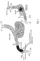
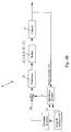
- FIG. 2 of the accompanying drawings shows a flexible endoscope device 1 comprising an elongate flexible body 2 having a flexible end segment 3 carrying or shaping the head 3 'of the endoscope, provided with an optical system 4 and being curvable or flexed in at least two mutually perpendicular directions.
- the elongated body 2 being functionally connected, at its other end, to a control means 5 able to control at least the movements and / or the disposition of said end segment 3.
- part of the video processing means 6, or that certain functions performed by the latter, are located in the optical system 4.
- the latter can also be in different embodiments, namely: a video camera embedded in the endoscope at the end segment 3 of the flexible elongate body 2; a bundle of optical fibers opening at the end segment 3 and connected to a video camera or similar external device (fiberscope); a bundle of optical microfibers mounted in the body 2 and connected to an external operating device (cellular fibroscopy device) or the like.
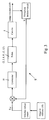
- the computer means 7 therefore produces a digital control by visual servoing and contains a software model of the complex physical system formed by the endoscope, these mechanical control means and its motorization, said modeling processing the input signals formed by the image reference 10 and the current image 10 'and outputting control signals for the means (s) actuator (s) 8, 8'.
- the images provided by the optical system 4 and used in the form of video images are used to control the movements of the flexible endoscope, more particularly of its head 3 '(see in this connection in particular: " A tutorial on visual servo control ", S. Hutchinson, GD Hager and PI Corke, IEEE Transactions on Robotics and Automation, Vol 12, 5, pp. 651-670, 1996 ).
- the working environment in which the head 3 'of the endoscope is located usually does not present particular visual cues such as points of interest, corners, contours of particular rigid shapes, straight lines or analogous, and therefore does not directly allow the application of known methods of extraction, coincidence, tracking and servocontrol, without setting up additional markers in the work environment.
- the computer means 7 is capable, by execution of a suitable program, of determining, in real time, that is to say at least at the speed of delivery of the video images, an approximation, preferentially by iterative processing, the transformation to be applied to the current image 10 'resulting in a minimization of a cost function between a reduced or imagined image T * obtained from the reference image 10 and a reduced image or image T obtained from the current image 10 'provided by the head 3' of the endoscope and processed by the current approximated transformation.
- the information useful for visual servoing relies on an algorithm of the type "visual reference thumbnail tracking".
- the reference zone is learned during the manual selection, by the practitioner, of the target zone to be stabilized.
- the monitoring of this zone is then ensured by minimizing a measure of dissimilarity between the reference thumbnail T * and the current thumbnail T.
- reference image is meant herein the image in which the practitioner has identified the anatomical target. It is normally constituted by an initial image or base provided by the video means connected to the endoscope 2 or possibly a stored image, for example a real image of the anatomical environment of the target acquired by selection.
- the minimization algorithm implemented by the computer means 7 performs a parametric minimization of the quadratic error between the visual or visual information elements T * and T respectively obtained from the image. reference 10 and from the current image 10 ', the approximated transformation being a plane transformation, for example, homographic type.
- the minimization algorithm may, for example, be derived from an ESM type algorithm, as described in particular in the publication " Improving vision-based control using efficient second-order minimization techniques ", MALIS E., IEEE Int.Conf.on Rob.Aut.A., Pages 1843-1848, 2004 .
- the minimization algorithm implemented by the computer means 7 performs a statistical minimization of a measurement of dissimilarity between histograms obtained from the visual elements or visual information T * and T respectively obtained from the reference image 10 and from the current image 10 ', the approximated transformation being composed of a translation in the image plane and a zoom (reduction or enlargement).
- the minimization algorithm can be derived from that known under the designation "mean-shift” algorithm, as described for example in: " Kermel-based object tracking ", D. Comanicin et al., Patterne Analysis and Machine Intelligence, IEEE Transactions on, Volume 25, May 5, 2003, pages: 564-577 .
- the vector of the variable S ref preparamétrée contains the image data to which the anatomical target must be stabilized. This point is initially selected by the practitioner on the reference image 10 and can be modified in the current image 10 '. The practitioner also specifies the point of interest of the anatomical target to stabilize s * in the reference image T *.
- One of the above-mentioned tracking algorithms is then used to reconstruct the transformation between the current image T and the reference image T *, this transformation being then used to determine the vectors containing the coordinates of the point to be stabilized in the current image. .
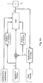
- the automatic positioning means 6, 7, 8, 8 ' are organized in a two-dimensional visual servocontrol loop and comprise two independent actuators 8 and 8' each controlling the movements and the positioning of the segment end 3 in one of the two mutually perpendicular directions corresponding to the two directions of the current planar image provided by the endoscope head 3 '.
- an independent control loop 9 is provided for each actuator means 8, 8 ', depending on the nature of the system.
- the controller or corrector 11 forming part of the control loop 9 can be chosen from the group formed by the controllers of the proportional type, of the proportional / integral / derivative type and of the predictive or repetitive type.
- controller 11 of the repetitive type as described for example in: " Analysis and Synthesis of Discrete-Time Repetitive Controllers ", M. Tomizuka et al., American Society of Mechanical Engineers Journal of Dynamic Systems, Measurement and Control, 111, 353-358, 1989 ; a controller of the R-GPC type as described for example in: Model Predictive Control for Panning of Cyclic Organ Motions in Teleoperated Laparoscopic Surgery, J. Gangloff et al., Control Systems Technology, IEEE Transactions on, Volume 14, Issue 2, March 2006, pages 235-246. .
- the controller 11 can also integrate a model of the perturbation, as for example in the predictive controller described in the publication of EF Camacho, Bordons C, Model Predictive Control, ISBN 3-540-76241-8 .
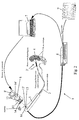
- the control means 5 comprises two concentric control axes 13 and 13 'each associated with a control cable 12, 12' flowing along the elongate body 2 and connected to the end segment 3 to control the bending or bending of said segment 3 in one of two mutually perpendicular bending directions, the outer axis 13 being in drive relation with a first actuator means 8 in the form of a hollow shaft motor 8 "via a transmission part 14 disengaged in a central region extending in the continuity of the hollow axis 8 "of said motor 8, and the inner axis 13 'being in driving relation, via a piece of elongate drive 14 ', with a second actuator means 8' in the form of a motor aligned with the first motor 8 along their axes of rotation, said elongate drive member 14 'passing through the first motor 8 at its hollow axis 8 ".
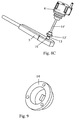
- the two motors 8 and 8 ' are mechanically assembled together to form a drive unit mounted on the handle 5 forming the control means, through a support part 15 and fastening, where appropriate in form unit with removable mechanical connection, thus allowing interchangeability with the manual control elements ( figure 2 ).
- the non-limiting embodiment of motorization of the control of a flexible endoscope illustrated on the figures 2 and 6 to 8 , more particularly relates to an endoscope type 13801 PKS KARL STORZ company.
- the motorization solution proposed by the invention makes it possible to preserve the existing internal structure of the endoscope, by recommending the replacement of the manual control wheels by the actuators 8 and 8 '.
- the latter are for example in the form of harmonic control motors (for example of the FHA-8C type) controlled by servocontrollers with a speed loop (for example of the Harmonic Drive SC-610 type). Said motors are connected directly to the control pins 13 and 13 ', by rigid mechanical connection and without clutch or articulation, in order to avoid as much play as possible.
- harmonic control motors for example of the FHA-8C type
- servocontrollers with a speed loop for example of the Harmonic Drive SC-610 type
- the endoscope device 1 being a mechanical system with 2 degrees of freedom
- the two x and y coordinates of a visual index of the point type in the image is a sufficient feedback variable. to control said system.
- the velocity of the visual index F (s) in the image is related to the velocity of the actuators Q by a 2x2 interaction matrix, which the inventors have chosen to estimate in a preliminary phase around the working configuration.
- the velocity vector of the actuators Q (s) * is sent as a reference to the speed loops of the power amplifiers controlling the motors of the actuators 8 and 8 '.
- the bandwidth of said speed loops being significantly greater than the sampling frequency of the visual servo loop 9, the dynamics of the actuators can be neglected and therefore Q (s) is approximately equal to Q (s) *.
- the main branch of the loop successively comprises the following elements: zero order corrector / blocker BOZ / integrator 1 / s / hysteresis module (set of sets of device 1) / interaction matrix J (s) / integrator 1 / s and the feedback branch comprises a delay element Z -1 which corresponds to the acquisition times of the images.
- This part 15 is furthermore configured in such a way as to ensure axial alignment of the motors 8 and 8 'with the concentric control axes 13 and 13'.
- This part 15 directly supports the lower motor 8 and indirectly the upper motor 8 ', the latter by means of an additional support member 15', simultaneously secured to said part 15 and to said motor 8 '( figures 2 and 6 ).
- the part 14 for transmitting the movement between the lower motor 8 and the external control shaft 13 has an unobstructed central region (in the axial direction of the two motors in the assembled state), and is provided at its bottom. a square cut for an engagement adjusted on the outer axis 13 and at its upper part of sites engagement with the output flange of the lower motor 8 with hollow shaft (for example connection pins / orifices).
- the driving part 14 ' ensuring the transmission of the movement between the upper motor 8' and the inner axis 13 ', comprises a lower connection portion (with a square section opening) intended to engage on said axis 13 and an upper connection interface in engagement with the upper motor output flange 8 '(e.g. via a lug / port connection).
- the upper motor 8 ' is maintained in axial alignment with the lower motor 8 and the control pins 13 and 13' via the additional support piece 15 '.
- the actuator means 8, 8 ' can also be in the form of motors directly housed in the handle forming the control means 5 and in driving relation each with a cable for controlling the bending deformation of the end segment 3.
- control means 5 may also comprise at least one member that can be manipulated by the practitioner, such as a thumbwheel, a joystick or the like, able to control at least one actuator 8, 8 ', alternatively or superimposed manner with respect to the automatic control by visual servoing, said member (s) being (s) mounted (s) at the handle 5, or remote (s) relative thereto.
- This method implements a flexible endoscope device 1 essentially comprising an elongate flexible body 2 having a flexible end segment 3 carrying or forming the endoscope head 3 ', provided with an optical system 4 and being curved or flexed according to at least two mutually perpendicular directions, said elongated body 2 being functionally connected at its other end (opposite or segment 3) to a control means 5 adapted to control at least the movements and / or the disposition of said end segment, plus particularly a device as described above.
- This method consists in automatically performing, by means of means 6, 7, 8 and 8 'of automatic bending and positioning of the end segment 3 organized functionally in at least one servo loop 9, a processing of the images provided. by the optical system 4 of the head 3 'of the endoscope, visual servoing operations on the basis of the processed video signals and the development and supply of control signals to actuator means 8, 8' forming part or associated with the control means 5.
- the servo-control operations essentially consist in minimizing the error or a similar measure of dissimilarity between, on the one hand, a target visual or visual information element extracted from a reference image 10 and, on the other hand, a corresponding visual or visual information element extracted from the current image 10 'provided by the optical system 4 of the endoscope head 3', said error being used to deliver control signals to the medium (s) actuator (s) 8, 8 'controlling the movements and the positioning of said end segment 3 in at least one direction.
- the visual or visual information elements are chosen from the group formed by the visual patterns, the image reductions and the image portions or zones respectively obtained from the reference image 10 and from the image current 10 'provided by the optical system 4, if appropriate after suitable treatment thereof.
- the method consists, in the context of servocontrol operations carried out by the computer means 7, to determine in real time, that is to say at least at the speed of supply of the video images. , an approximation, preferably by iterative processing, of the transformation to be applied to the current image 10 'resulting in a minimization of a cost function between a reduced or an imaginary image T * obtained from the reference image 10 and a reduced or enlarged image obtained from the reference image 10 'provided by the endoscope head 3' and processed by the current approximated transformation.
- the latter can consist in implementing a minimization algorithm performing a parametric minimization of the quadratic error between the visual or visual information elements T * and T respectively obtained from the image of reference 10 and from the current image 10 ', the approximated transformation being a plane transformation, for example of a homographic type.
- the latter can consist in implementing a minimization algorithm achieving a statistical minimization of a measure of dissimilarity between histograms obtained from the visual elements or visual information T * and T respectively obtained at from the reference image 10 and from the current image 10 ', the approximated transformation being composed of a translation in the image plane and a zoom.
- the movements and positioning of the end segment 3 ' are controlled by two independent actuators 8 and 8' each associated with one of two perpendicular directions corresponding to two directions of the current plane image 10 ' repeatedly provided by the endoscope head 3 '.
- the parameterization phase may consist, for the practitioner, in determining the reference s ref of the servocontrol loop 9, in the form of appropriate visual cues (for example x, y coordinates of a point) selected in an image of 10, to control the various degrees of freedom of the flexible endoscope, in particular of its free end 3.
Landscapes
- Health & Medical Sciences (AREA)
- Life Sciences & Earth Sciences (AREA)
- Surgery (AREA)
- Biomedical Technology (AREA)
- Medical Informatics (AREA)
- Optics & Photonics (AREA)
- Pathology (AREA)
- Radiology & Medical Imaging (AREA)
- Biophysics (AREA)
- Engineering & Computer Science (AREA)
- Physics & Mathematics (AREA)
- Heart & Thoracic Surgery (AREA)
- Nuclear Medicine, Radiotherapy & Molecular Imaging (AREA)
- Molecular Biology (AREA)
- Animal Behavior & Ethology (AREA)
- General Health & Medical Sciences (AREA)
- Public Health (AREA)
- Veterinary Medicine (AREA)
- Endoscopes (AREA)
- Instruments For Viewing The Inside Of Hollow Bodies (AREA)
Claims (8)
- Flexible Endoskopvorrichtung,
wobei diese Vorrichtung (1) einen länglichen, nachgiebigen Körper (2) umfasst, der einen flexiblen Endabschnitt (3) aufweist, der den Kopf des Endoskops trägt oder bildet, der mit einem optischen System (4) ausgestattet ist und in mindestens zwei aufeinander senkrecht stehenden Richtungen gebogen oder gekrümmt werden kann, wobei der genannte längliche Körper (2) an seinem anderen Ende mit einem Bedienungsmittel (5) funktionell verbunden ist, das in der Lage ist, mindestens die Bewegungen und/oder die Anordnung des genannten Endabschnitts zu steuern,
wobei diese Vorrichtung (1) ebenfalls automatische Orientierungs- und Positionierungsmittel für den Endabschnitt (3) durch visuelle Regelung umfasst, die im Wesentlichen aus einem Videoverarbeitungsmittel (6) bestehen, das die Videobilder oder -signale empfängt, die vom optischen System (4) des Endoskopkopfes (3') ausgegeben werden, aus einem Datenverarbeitungsmittel (7), das in der Lage ist, visuelle Regelvorgänge auf der Grundlage der verarbeiteten Videosignale auszuführen und Steuersignale ausgibt, und aus Aktuatormitteln (8, 8'), die Teil der Bedienungsmittel (5) sind oder ihnen zugeordnet sind und die in der Lage sind, den Endabschnitt (3) zu steuern, und die die Steuersignale empfangen, die von den Datenverarbeitungsmitteln (7) ausgegeben werden, wobei die automatischen Orientierungs- und Positionierungsmittel (6, 7, 8, 8', 12, 12') für den Endabschnitt (3) derart funktionell organisiert sind, dass sie mindestens eine Regelschleife (9) bilden, die dazu dient, Fehler oder ein analoges Abweichungsmaß zwischen einerseits einem visuellen Zielelement oder einem Zielelement visueller Information zu minimieren, das einem Referenzbild (10) entnommen wurde, und andererseits einem entsprechenden visuellen Element oder Element visueller Information, das dem laufenden Bild (10') entnommen wurde, das vom optischen System (4) des Endoskopkopfes (3') stammt, wobei der genannte Fehler verwendet wird, um Steuersignale an das/die Aktuatormittel (8, 8') auszugeben, die die Bewegungen und die Positionierung des genannten Endabschnittes (3) in mindestens einer Richtung steuern,
wobei das Datenverarbeitungsmittel (7) in der Lage ist, durch Ausführung eines entsprechenden Programms in Echtzeit, d.h. mindestens mit der Ausgabegeschwindigkeit der Videobilder, eine Approximation, vorzugsweise durch eine iterative Verarbeitung der auf das laufende Bild (10') anzuwendenden Transformation zu bestimmen, um dieses letztere dem Referenzbild anzunähern, wobei die automatischen Positionierungsmittel (6, 7, 8, 8') in einer zweidimensionalen visuellen Regelschleife organisiert sind und zwei unabhängige Aktuatormittel (8, 8') umfassen, die jeweils die Bewegungen und die Positionierung des Endabschnitts (3) in einer der beiden aufeinander senkrecht stehenden Richtungen, die zwei Richtungen des ebenen laufenden Bildes (10') entsprechen, das vom Endoskopkopf (3') ausgegeben wird, steuern,
Vorrichtung (1), dadurch gekennzeichnet, dass
das vom Datenverarbeitungsmittel (7) im Rahmen der Regelvorgänge ausgeführte Programm die Approximation durch Minimierung einer Kostenfunktion zwischen einem reduzierten Bild oder Bildchen (T*), das aus dem Referenzbild (10) gewonnen wurde, und einem reduzierten Bild oder Bildchen (T), das aus dem laufenden Bild (10') gewonnen wurde, das vom Endoskopkopf (3') ausgegeben wurde und durch die laufende approximierte Transformation verarbeitet wurde, ausführt, wobei die reduzierten Bilder oder Bildchen die visuellen Zielelemente oder Zielelemente visueller Information enthalten, die dem Referenzbild und dem laufenden Bild entnommen wurden, und
dadurch, dass das Bedienungsmittel (5) zwei konzentrische Steuerachsen (13 und 13') aufweist, die jeweils mit einem Steuerkabel (12, 12') verbunden sind, das am länglichen Körper (2) entlangläuft und am Endabschnitt (3) befestigt ist, um die Biegung oder Krümmung des genannten Abschnitts (3) in einer der beiden aufeinander senkrecht stehenden Biegungsrichtungen zu steuern, wobei die äußere Achse (13) über ein Antriebsteil (14) mit einem ersten Aktuatormittel (8) in Form eines Motors mit Hohlachse (8") in Antriebsbeziehung steht, wobei das Antriebsteil in einem zentralen Bereich ausgebildet ist, der sich in der Fortsetzung der Hohlachse (8") des genannten Motors (8) erstreckt, und die innere Achse (13') über ein langgestrecktes Antriebsteil (14') mit einem zweiten Aktuatormittel (8') in Form eines Motors in Antriebsbeziehung steht, der mit dem ersten Motor (8) längs ihrer Drehachsen ausgerichtet ist, wobei das genannte langgestreckte Antriebsteil (14') den ersten Motor (8) im Bereich seiner Hohlachse (8") durchquert. - Vorrichtung nach Patentanspruch 1, dadurch gekennzeichnet, dass die visuellen Elemente oder Elemente visueller Information aus der Gruppe gewählt werden, die aus den visuellen Motiven, den Bildverkleinerungen und den Bereichen oder Abschnitten von Bildern, die aus dem Referenzbild (10) in Form eines Ausgangs- oder Basisbildes, das das optische System (4) ausgibt, oder einem realen, durch Auswahl gewonnenen Bild der anatomischen Umgebung des Ziels besteht, gewonnen wurden und aus dem laufenden Bild (10'), das aus dem optischen System (4) stammt, gegebenenfalls nach dessen entsprechender Verarbeitung.
- Vorrichtung nach Patentanspruch 1 oder 2, dadurch gekennzeichnet, dass der vom Datenverarbeitungsmittel (7) ausgeführte Minimierungsalgorithmus eine parametrische Minimierung des quadratischen Fehlers zwischen den visuellen Elementen oder Elementen visueller Information (T* und T), die aus dem Referenzbild (10) bzw. aus dem laufenden Bild (10') stammen, ausführt, wobei die approximierte Transformation eine Ebenentransformation beispielsweise der Art einer Homographie ist.
- Vorrichtung nach Patentanspruch 1 oder 2, dadurch gekennzeichnet, dass der vom Datenverarbeitungsmittel (7) angewandte Minimierungsalgorithmus eine statistische Minimierung eines Abweichungsmaßes zwischen aus den visuellen Elementen oder Elementen visueller Information (T* und T), die aus dem Referenzbild (10) bzw. aus dem laufenden Bild (10') stammen, erhaltenen Histogrammen ausführt, wobei die approximierte Transformation aus einer Translation in der Bildebene und einem Zoom besteht.
- Vorrichtung nach Patentanspruch 1 bis 4, dadurch gekennzeichnet, dass für jedes Aktuatormittel (8, 8') eine unabhängige Regelschleife vorgesehen ist.
- Vorrichtung nach irgendeinem der Patentansprüche 1 bis 5, dadurch gekennzeichnet, dass der Regler oder Korrektor (11), der der Regelschleife (9) angehört, aus der Gruppe, bestehend aus den Proportional reg lern, Proportional-Integral-Differential-Reglern und den prädiktiven oder repetitiven Reglern, ausgewählt wird.
- Vorrichtung nach irgendeinem der Patentansprüche 1 bis 6, dadurch gekennzeichnet, dass die beiden Motoren (8 und 8') miteinander mechanisch zusammengesetzt sind, um eine Motorisierungseinheit zu bilden, die am Griff (5), der das Bedienungsmittel bildet, durch ein Trage- und Befestigungsstück (15), gegebenenfalls in Form einer Einheit zum abnehmbaren mechanischen Anschluss, montiert sind.
- Vorrichtung nach Patentanspruch 7, dadurch gekennzeichnet, dass sie mindestens ein durch den Benutzer betätigbares Organ, wie etwa ein Rändelrad, einen Bedienungshebel oder Ähnliches, aufweist, das in der Lage ist, mindestens ein Aktuatormittel (8, 8') zu steuern, alternativ oder zusätzlich zur automatischen Steuerung durch visuelle Regelung, wobei das genannte Organ entweder im Bereich des Griffes (5) montiert ist oder von diesem entfernt.
Applications Claiming Priority (2)
| Application Number | Priority Date | Filing Date | Title |
|---|---|---|---|
| US90286207P | 2007-02-23 | 2007-02-23 | |
| PCT/FR2008/050312 WO2008113957A1 (fr) | 2007-02-23 | 2008-02-25 | Dispositif d'endoscope flexible a asservissement visuel et procede de stabilisation d'un tel dispositif |
Publications (2)
| Publication Number | Publication Date |
|---|---|
| EP2124709A1 EP2124709A1 (de) | 2009-12-02 |
| EP2124709B1 true EP2124709B1 (de) | 2016-08-31 |
Family
ID=39676170
Family Applications (1)
| Application Number | Title | Priority Date | Filing Date |
|---|---|---|---|
| EP08762153.8A Not-in-force EP2124709B1 (de) | 2007-02-23 | 2008-02-25 | Flexible endoskopvorrichtung mit visueller kontrolle |
Country Status (4)
| Country | Link |
|---|---|
| US (1) | US20100168518A1 (de) |
| EP (1) | EP2124709B1 (de) |
| JP (1) | JP2010518954A (de) |
| WO (1) | WO2008113957A1 (de) |
Families Citing this family (4)
| Publication number | Priority date | Publication date | Assignee | Title |
|---|---|---|---|---|
| DE102008018723B3 (de) * | 2008-04-14 | 2009-07-16 | Siemens Aktiengesellschaft | Verfahren zur Bewegungssteuerung einer Endoskopiekapsel |
| US8934003B2 (en) * | 2010-01-08 | 2015-01-13 | Koninklijkle Philips N.V. | Uncalibrated visual servoing using real-time velocity optimization |
| US10299773B2 (en) * | 2011-08-21 | 2019-05-28 | Transenterix Europe S.A.R.L. | Device and method for assisting laparoscopic surgery—rule based approach |
| US9668768B2 (en) | 2013-03-15 | 2017-06-06 | Synaptive Medical (Barbados) Inc. | Intelligent positioning system and methods therefore |
Citations (2)
| Publication number | Priority date | Publication date | Assignee | Title |
|---|---|---|---|---|
| US5906578A (en) * | 1997-06-18 | 1999-05-25 | Rajan; Govinda N. | Method and system for probe positioning in transesophageal echocardiography |
| US20040097789A1 (en) * | 2002-11-18 | 2004-05-20 | Weinberg Andrew Mark | Colonoscope apparatus and method |
Family Cites Families (7)
| Publication number | Priority date | Publication date | Assignee | Title |
|---|---|---|---|---|
| US5347987A (en) * | 1991-04-08 | 1994-09-20 | Feldstein David A | Self-centering endoscope system |
| DE19529950C1 (de) * | 1995-08-14 | 1996-11-14 | Deutsche Forsch Luft Raumfahrt | Verfahren zum Nachführen eines Stereo-Laparoskops in der minimalinvasiven Chirurgie |
| US5951461A (en) * | 1996-12-20 | 1999-09-14 | Nyo; Tin | Image-guided laryngoscope for tracheal intubation |
| WO2002065069A2 (en) * | 2000-11-07 | 2002-08-22 | Hypermed, Inc. | Hyperspectral imaging calibration device |
| US6695774B2 (en) * | 2001-01-19 | 2004-02-24 | Endactive, Inc. | Apparatus and method for controlling endoscopic instruments |
| US8721655B2 (en) * | 2002-04-10 | 2014-05-13 | Stereotaxis, Inc. | Efficient closed loop feedback navigation |
| JP3973504B2 (ja) * | 2002-07-15 | 2007-09-12 | 株式会社日立製作所 | 牽引位置決め装置 |
-
2008
- 2008-02-25 EP EP08762153.8A patent/EP2124709B1/de not_active Not-in-force
- 2008-02-25 JP JP2009550745A patent/JP2010518954A/ja not_active Withdrawn
- 2008-02-25 US US12/528,254 patent/US20100168518A1/en not_active Abandoned
- 2008-02-25 WO PCT/FR2008/050312 patent/WO2008113957A1/fr not_active Ceased
Patent Citations (2)
| Publication number | Priority date | Publication date | Assignee | Title |
|---|---|---|---|---|
| US5906578A (en) * | 1997-06-18 | 1999-05-25 | Rajan; Govinda N. | Method and system for probe positioning in transesophageal echocardiography |
| US20040097789A1 (en) * | 2002-11-18 | 2004-05-20 | Weinberg Andrew Mark | Colonoscope apparatus and method |
Also Published As
| Publication number | Publication date |
|---|---|
| EP2124709A1 (de) | 2009-12-02 |
| US20100168518A1 (en) | 2010-07-01 |
| JP2010518954A (ja) | 2010-06-03 |
| WO2008113957A1 (fr) | 2008-09-25 |
Similar Documents
| Publication | Publication Date | Title |
|---|---|---|
| US11000339B2 (en) | System and apparatus for positioning an instrument in a body cavity for performing a surgical procedure | |
| EP2306911B1 (de) | Modulares chirurgisches instrument | |
| CN111632251B (zh) | 导管系统 | |
| JP6310455B2 (ja) | ロボット遠隔運動中心のコントローラ定義 | |
| CN106236277B (zh) | 输入装置上的力反馈的应用促使其操作者命令关节式仪器摆成优选姿势 | |
| US20240382279A1 (en) | Surgical instrument cable control and routing structures | |
| CN117731218A (zh) | 虚拟现实外科手术摄像机系统 | |
| US20140316203A1 (en) | Surgeon Controlled Endoscope Device and Method | |
| US12004717B2 (en) | Endoscope with detachable camera module | |
| JP2017525499A (ja) | 医療器具力検知のためのシステム及び方法 | |
| KR20120014242A (ko) | 하나 이상의 랜드마크를 향해 내시경 디바이스의 팁을 조종하고 운전자의 내시경 길찾기를 돕기 위한 시각적 안내를 제공하는 시스템 | |
| CN103607941A (zh) | 用于操纵医疗器械通过连接的人体通道的具有多种操作模式的医疗系统 | |
| US20140343568A1 (en) | Guide apparatus for delivery of a flexible instrument and methods of use | |
| EP3272269B1 (de) | Chirurgenseitig gesteuerte endoskopvorrichtung und verfahren | |
| WO2023039931A1 (zh) | 一种柔性手术器械控制装置及内镜手术机器人系统 | |
| EP2124709B1 (de) | Flexible endoskopvorrichtung mit visueller kontrolle | |
| KR20210010495A (ko) | 카테터 제어 시스템의 백엔드 메커니즘 | |
| EP1196108A1 (de) | Auf einem patienten fernsteuerbares positionierungssystem für eine überwachungs- bzw. eingriffsvorrichtung | |
| US20220079696A1 (en) | Systems for coupling and storing an imaging instrument | |
| US20230310807A1 (en) | Instrument with a counter-pivoting mechanism | |
| FR3158628A1 (fr) | Robot médical collaboratif pour guider l’insertion d’instruments | |
| US20250235088A1 (en) | Tool drive adaptor for robotic surgical instrument | |
| Li et al. | Compact manipulator with flexible parallel mechanisms and variable stiffness for keyhole procedures | |
| Wang et al. | Development and Autonomous Tracking of Miniature Continuum Endscope for Intraocular Microsurgery | |
| JP6531174B2 (ja) | 内視鏡用外科手術装置及び案内装置 |
Legal Events
| Date | Code | Title | Description |
|---|---|---|---|
| PUAI | Public reference made under article 153(3) epc to a published international application that has entered the european phase |
Free format text: ORIGINAL CODE: 0009012 |
|
| 17P | Request for examination filed |
Effective date: 20090922 |
|
| AK | Designated contracting states |
Kind code of ref document: A1 Designated state(s): AT BE BG CH CY CZ DE DK EE ES FI FR GB GR HR HU IE IS IT LI LT LU LV MC MT NL NO PL PT RO SE SI SK TR |
|
| DAX | Request for extension of the european patent (deleted) | ||
| 17Q | First examination report despatched |
Effective date: 20140212 |
|
| GRAP | Despatch of communication of intention to grant a patent |
Free format text: ORIGINAL CODE: EPIDOSNIGR1 |
|
| INTG | Intention to grant announced |
Effective date: 20160322 |
|
| RAP1 | Party data changed (applicant data changed or rights of an application transferred) |
Owner name: UNIVERSITE DE STRASBOURG (ETABLISSEMENT PUBLIC A C Owner name: CENTRE NATIONAL DE LA RECHERCHE SCIENTIFIQUE |
|
| RIN1 | Information on inventor provided before grant (corrected) |
Inventor name: OTT, LAURENT Inventor name: DE MATHELIN, MICHEL Inventor name: GANGLOFF, JACQUES Inventor name: ZANNE, PHILIPPE |
|
| GRAS | Grant fee paid |
Free format text: ORIGINAL CODE: EPIDOSNIGR3 |
|
| GRAA | (expected) grant |
Free format text: ORIGINAL CODE: 0009210 |
|
| AK | Designated contracting states |
Kind code of ref document: B1 Designated state(s): AT BE BG CH CY CZ DE DK EE ES FI FR GB GR HR HU IE IS IT LI LT LU LV MC MT NL NO PL PT RO SE SI SK TR |
|
| REG | Reference to a national code |
Ref country code: CH Ref legal event code: EP Ref country code: GB Ref legal event code: FG4D Free format text: NOT ENGLISH |
|
| REG | Reference to a national code |
Ref country code: IE Ref legal event code: FG4D Free format text: LANGUAGE OF EP DOCUMENT: FRENCH |
|
| REG | Reference to a national code |
Ref country code: DE Ref legal event code: R096 Ref document number: 602008046002 Country of ref document: DE |
|
| REG | Reference to a national code |
Ref country code: AT Ref legal event code: REF Ref document number: 824209 Country of ref document: AT Kind code of ref document: T Effective date: 20161015 |
|
| REG | Reference to a national code |
Ref country code: LT Ref legal event code: MG4D |
|
| REG | Reference to a national code |
Ref country code: NL Ref legal event code: MP Effective date: 20160831 |
|
| REG | Reference to a national code |
Ref country code: AT Ref legal event code: MK05 Ref document number: 824209 Country of ref document: AT Kind code of ref document: T Effective date: 20160831 |
|
| REG | Reference to a national code |
Ref country code: FR Ref legal event code: PLFP Year of fee payment: 10 |
|
| PG25 | Lapsed in a contracting state [announced via postgrant information from national office to epo] |
Ref country code: HR Free format text: LAPSE BECAUSE OF FAILURE TO SUBMIT A TRANSLATION OF THE DESCRIPTION OR TO PAY THE FEE WITHIN THE PRESCRIBED TIME-LIMIT Effective date: 20160831 Ref country code: NO Free format text: LAPSE BECAUSE OF FAILURE TO SUBMIT A TRANSLATION OF THE DESCRIPTION OR TO PAY THE FEE WITHIN THE PRESCRIBED TIME-LIMIT Effective date: 20161130 Ref country code: FI Free format text: LAPSE BECAUSE OF FAILURE TO SUBMIT A TRANSLATION OF THE DESCRIPTION OR TO PAY THE FEE WITHIN THE PRESCRIBED TIME-LIMIT Effective date: 20160831 Ref country code: LT Free format text: LAPSE BECAUSE OF FAILURE TO SUBMIT A TRANSLATION OF THE DESCRIPTION OR TO PAY THE FEE WITHIN THE PRESCRIBED TIME-LIMIT Effective date: 20160831 |
|
| PG25 | Lapsed in a contracting state [announced via postgrant information from national office to epo] |
Ref country code: SE Free format text: LAPSE BECAUSE OF FAILURE TO SUBMIT A TRANSLATION OF THE DESCRIPTION OR TO PAY THE FEE WITHIN THE PRESCRIBED TIME-LIMIT Effective date: 20160831 Ref country code: ES Free format text: LAPSE BECAUSE OF FAILURE TO SUBMIT A TRANSLATION OF THE DESCRIPTION OR TO PAY THE FEE WITHIN THE PRESCRIBED TIME-LIMIT Effective date: 20160831 Ref country code: GR Free format text: LAPSE BECAUSE OF FAILURE TO SUBMIT A TRANSLATION OF THE DESCRIPTION OR TO PAY THE FEE WITHIN THE PRESCRIBED TIME-LIMIT Effective date: 20161201 Ref country code: AT Free format text: LAPSE BECAUSE OF FAILURE TO SUBMIT A TRANSLATION OF THE DESCRIPTION OR TO PAY THE FEE WITHIN THE PRESCRIBED TIME-LIMIT Effective date: 20160831 Ref country code: NL Free format text: LAPSE BECAUSE OF FAILURE TO SUBMIT A TRANSLATION OF THE DESCRIPTION OR TO PAY THE FEE WITHIN THE PRESCRIBED TIME-LIMIT Effective date: 20160831 Ref country code: LV Free format text: LAPSE BECAUSE OF FAILURE TO SUBMIT A TRANSLATION OF THE DESCRIPTION OR TO PAY THE FEE WITHIN THE PRESCRIBED TIME-LIMIT Effective date: 20160831 |
|
| PG25 | Lapsed in a contracting state [announced via postgrant information from national office to epo] |
Ref country code: EE Free format text: LAPSE BECAUSE OF FAILURE TO SUBMIT A TRANSLATION OF THE DESCRIPTION OR TO PAY THE FEE WITHIN THE PRESCRIBED TIME-LIMIT Effective date: 20160831 Ref country code: RO Free format text: LAPSE BECAUSE OF FAILURE TO SUBMIT A TRANSLATION OF THE DESCRIPTION OR TO PAY THE FEE WITHIN THE PRESCRIBED TIME-LIMIT Effective date: 20160831 |
|
| PG25 | Lapsed in a contracting state [announced via postgrant information from national office to epo] |
Ref country code: DK Free format text: LAPSE BECAUSE OF FAILURE TO SUBMIT A TRANSLATION OF THE DESCRIPTION OR TO PAY THE FEE WITHIN THE PRESCRIBED TIME-LIMIT Effective date: 20160831 Ref country code: CZ Free format text: LAPSE BECAUSE OF FAILURE TO SUBMIT A TRANSLATION OF THE DESCRIPTION OR TO PAY THE FEE WITHIN THE PRESCRIBED TIME-LIMIT Effective date: 20160831 Ref country code: BE Free format text: LAPSE BECAUSE OF NON-PAYMENT OF DUE FEES Effective date: 20170228 Ref country code: SK Free format text: LAPSE BECAUSE OF FAILURE TO SUBMIT A TRANSLATION OF THE DESCRIPTION OR TO PAY THE FEE WITHIN THE PRESCRIBED TIME-LIMIT Effective date: 20160831 Ref country code: BG Free format text: LAPSE BECAUSE OF FAILURE TO SUBMIT A TRANSLATION OF THE DESCRIPTION OR TO PAY THE FEE WITHIN THE PRESCRIBED TIME-LIMIT Effective date: 20161130 Ref country code: PT Free format text: LAPSE BECAUSE OF FAILURE TO SUBMIT A TRANSLATION OF THE DESCRIPTION OR TO PAY THE FEE WITHIN THE PRESCRIBED TIME-LIMIT Effective date: 20170102 Ref country code: PL Free format text: LAPSE BECAUSE OF FAILURE TO SUBMIT A TRANSLATION OF THE DESCRIPTION OR TO PAY THE FEE WITHIN THE PRESCRIBED TIME-LIMIT Effective date: 20160831 |
|
| PGFP | Annual fee paid to national office [announced via postgrant information from national office to epo] |
Ref country code: GB Payment date: 20170209 Year of fee payment: 10 |
|
| REG | Reference to a national code |
Ref country code: DE Ref legal event code: R097 Ref document number: 602008046002 Country of ref document: DE |
|
| PG25 | Lapsed in a contracting state [announced via postgrant information from national office to epo] |
Ref country code: IT Free format text: LAPSE BECAUSE OF FAILURE TO SUBMIT A TRANSLATION OF THE DESCRIPTION OR TO PAY THE FEE WITHIN THE PRESCRIBED TIME-LIMIT Effective date: 20160831 |
|
| PLBE | No opposition filed within time limit |
Free format text: ORIGINAL CODE: 0009261 |
|
| STAA | Information on the status of an ep patent application or granted ep patent |
Free format text: STATUS: NO OPPOSITION FILED WITHIN TIME LIMIT |
|
| 26N | No opposition filed |
Effective date: 20170601 |
|
| PG25 | Lapsed in a contracting state [announced via postgrant information from national office to epo] |
Ref country code: SI Free format text: LAPSE BECAUSE OF FAILURE TO SUBMIT A TRANSLATION OF THE DESCRIPTION OR TO PAY THE FEE WITHIN THE PRESCRIBED TIME-LIMIT Effective date: 20160831 |
|
| PG25 | Lapsed in a contracting state [announced via postgrant information from national office to epo] |
Ref country code: MC Free format text: LAPSE BECAUSE OF FAILURE TO SUBMIT A TRANSLATION OF THE DESCRIPTION OR TO PAY THE FEE WITHIN THE PRESCRIBED TIME-LIMIT Effective date: 20160831 |
|
| REG | Reference to a national code |
Ref country code: CH Ref legal event code: PL |
|
| PG25 | Lapsed in a contracting state [announced via postgrant information from national office to epo] |
Ref country code: LI Free format text: LAPSE BECAUSE OF NON-PAYMENT OF DUE FEES Effective date: 20170228 Ref country code: CH Free format text: LAPSE BECAUSE OF NON-PAYMENT OF DUE FEES Effective date: 20170228 |
|
| REG | Reference to a national code |
Ref country code: IE Ref legal event code: MM4A |
|
| PG25 | Lapsed in a contracting state [announced via postgrant information from national office to epo] |
Ref country code: LU Free format text: LAPSE BECAUSE OF NON-PAYMENT OF DUE FEES Effective date: 20170225 |
|
| REG | Reference to a national code |
Ref country code: BE Ref legal event code: MM Effective date: 20170228 |
|
| PG25 | Lapsed in a contracting state [announced via postgrant information from national office to epo] |
Ref country code: IE Free format text: LAPSE BECAUSE OF NON-PAYMENT OF DUE FEES Effective date: 20170225 |
|
| REG | Reference to a national code |
Ref country code: FR Ref legal event code: PLFP Year of fee payment: 11 |
|
| PG25 | Lapsed in a contracting state [announced via postgrant information from national office to epo] |
Ref country code: MT Free format text: LAPSE BECAUSE OF FAILURE TO SUBMIT A TRANSLATION OF THE DESCRIPTION OR TO PAY THE FEE WITHIN THE PRESCRIBED TIME-LIMIT Effective date: 20160831 |
|
| GBPC | Gb: european patent ceased through non-payment of renewal fee |
Effective date: 20180225 |
|
| PG25 | Lapsed in a contracting state [announced via postgrant information from national office to epo] |
Ref country code: GB Free format text: LAPSE BECAUSE OF NON-PAYMENT OF DUE FEES Effective date: 20180225 |
|
| PG25 | Lapsed in a contracting state [announced via postgrant information from national office to epo] |
Ref country code: HU Free format text: LAPSE BECAUSE OF FAILURE TO SUBMIT A TRANSLATION OF THE DESCRIPTION OR TO PAY THE FEE WITHIN THE PRESCRIBED TIME-LIMIT; INVALID AB INITIO Effective date: 20080225 |
|
| PG25 | Lapsed in a contracting state [announced via postgrant information from national office to epo] |
Ref country code: CY Free format text: LAPSE BECAUSE OF NON-PAYMENT OF DUE FEES Effective date: 20160831 |
|
| PG25 | Lapsed in a contracting state [announced via postgrant information from national office to epo] |
Ref country code: TR Free format text: LAPSE BECAUSE OF FAILURE TO SUBMIT A TRANSLATION OF THE DESCRIPTION OR TO PAY THE FEE WITHIN THE PRESCRIBED TIME-LIMIT Effective date: 20160831 |
|
| PG25 | Lapsed in a contracting state [announced via postgrant information from national office to epo] |
Ref country code: IS Free format text: LAPSE BECAUSE OF FAILURE TO SUBMIT A TRANSLATION OF THE DESCRIPTION OR TO PAY THE FEE WITHIN THE PRESCRIBED TIME-LIMIT Effective date: 20161231 |
|
| PGFP | Annual fee paid to national office [announced via postgrant information from national office to epo] |
Ref country code: FR Payment date: 20210226 Year of fee payment: 14 |
|
| PGFP | Annual fee paid to national office [announced via postgrant information from national office to epo] |
Ref country code: DE Payment date: 20210226 Year of fee payment: 14 |
|
| REG | Reference to a national code |
Ref country code: DE Ref legal event code: R119 Ref document number: 602008046002 Country of ref document: DE |
|
| PG25 | Lapsed in a contracting state [announced via postgrant information from national office to epo] |
Ref country code: FR Free format text: LAPSE BECAUSE OF NON-PAYMENT OF DUE FEES Effective date: 20220228 |
|
| PG25 | Lapsed in a contracting state [announced via postgrant information from national office to epo] |
Ref country code: DE Free format text: LAPSE BECAUSE OF NON-PAYMENT OF DUE FEES Effective date: 20220901 |