EP2031736A2 - Brushless motor and electric power steering apparatus - Google Patents
Brushless motor and electric power steering apparatus Download PDFInfo
- Publication number
- EP2031736A2 EP2031736A2 EP08162946A EP08162946A EP2031736A2 EP 2031736 A2 EP2031736 A2 EP 2031736A2 EP 08162946 A EP08162946 A EP 08162946A EP 08162946 A EP08162946 A EP 08162946A EP 2031736 A2 EP2031736 A2 EP 2031736A2
- Authority
- EP
- European Patent Office
- Prior art keywords
- main portion
- brushless motor
- bus bars
- motor according
- coils
- Prior art date
- Legal status (The legal status is an assumption and is not a legal conclusion. Google has not performed a legal analysis and makes no representation as to the accuracy of the status listed.)
- Granted
Links
- 239000012212 insulator Substances 0.000 claims abstract description 42
- 229910052751 metal Inorganic materials 0.000 claims description 3
- 239000002184 metal Substances 0.000 claims description 3
- 238000004804 winding Methods 0.000 abstract description 14
- 239000012080 ambient air Substances 0.000 abstract description 4
- 238000005192 partition Methods 0.000 description 8
- 230000007246 mechanism Effects 0.000 description 7
- 230000005855 radiation Effects 0.000 description 7
- 239000011248 coating agent Substances 0.000 description 5
- 238000000576 coating method Methods 0.000 description 5
- 230000009467 reduction Effects 0.000 description 5
- 239000011347 resin Substances 0.000 description 4
- 229920005989 resin Polymers 0.000 description 4
- 238000003466 welding Methods 0.000 description 3
- 238000010586 diagram Methods 0.000 description 2
- 239000007769 metal material Substances 0.000 description 2
- 238000004080 punching Methods 0.000 description 2
- 229910000838 Al alloy Inorganic materials 0.000 description 1
- 238000005452 bending Methods 0.000 description 1
- 238000010292 electrical insulation Methods 0.000 description 1
- 230000004907 flux Effects 0.000 description 1
- 230000006872 improvement Effects 0.000 description 1
- 238000003780 insertion Methods 0.000 description 1
- 230000037431 insertion Effects 0.000 description 1
- 239000006247 magnetic powder Substances 0.000 description 1
- 239000000463 material Substances 0.000 description 1
- 230000013011 mating Effects 0.000 description 1
- 238000002844 melting Methods 0.000 description 1
- 230000008018 melting Effects 0.000 description 1
- 238000000034 method Methods 0.000 description 1
- 230000007935 neutral effect Effects 0.000 description 1
- 238000005245 sintering Methods 0.000 description 1
- 238000005476 soldering Methods 0.000 description 1
Images


Classifications
-
- H—ELECTRICITY
- H02—GENERATION; CONVERSION OR DISTRIBUTION OF ELECTRIC POWER
- H02K—DYNAMO-ELECTRIC MACHINES
- H02K3/00—Details of windings
- H02K3/46—Fastening of windings on the stator or rotor structure
- H02K3/52—Fastening salient pole windings or connections thereto
- H02K3/521—Fastening salient pole windings or connections thereto applicable to stators only
- H02K3/522—Fastening salient pole windings or connections thereto applicable to stators only for generally annular cores with salient poles
-
- H—ELECTRICITY
- H02—GENERATION; CONVERSION OR DISTRIBUTION OF ELECTRIC POWER
- H02K—DYNAMO-ELECTRIC MACHINES
- H02K1/00—Details of the magnetic circuit
- H02K1/06—Details of the magnetic circuit characterised by the shape, form or construction
- H02K1/12—Stationary parts of the magnetic circuit
- H02K1/14—Stator cores with salient poles
- H02K1/146—Stator cores with salient poles consisting of a generally annular yoke with salient poles
- H02K1/148—Sectional cores
-
- H—ELECTRICITY
- H02—GENERATION; CONVERSION OR DISTRIBUTION OF ELECTRIC POWER
- H02K—DYNAMO-ELECTRIC MACHINES
- H02K2203/00—Specific aspects not provided for in the other groups of this subclass relating to the windings
- H02K2203/09—Machines characterised by wiring elements other than wires, e.g. bus rings, for connecting the winding terminations
Definitions
- the present invention relates to a brushless motor, and more particularly, to a brushless motor including an improved bus bar and an electric power steering apparatus using such a motor.
- An electric power steering (EPS) apparatus using a motor as a drive source is nowadays often used as a vehicle power steering device.
- Such an EPS uses a brushless motor including a stator core, which has teeth extending radially inward, and a coil, which is formed by winding a conductive wire onto each tooth.
- Japanese Laid-Open Patent Publication No. 2006-296147 describes a prior art example of a brushless motor.
- an independent conductive wire is wound on each tooth to form a coil.
- the motor includes a bus bar for connecting ends of the coil supplied with current of the same phase and for supplying each coil with current from an external device.
- the bus bar is arranged in a housing in a state embedded in a bus bar holder formed from a resin.
- Resin usually has low thermal conductivity.
- the bus holder that is arranged in the housing makes it difficult to radiate the heat out of the housing.
- an increase in the temperature of the coil increases the electrical resistance of the coil. This increases voltage drop at the coil, which in turn may lower output of the motor.
- the EPS cannot apply an appropriate assist force to a steering system when sudden steering (high-speed steering) operations are performed. This may result in an uncomfortable steering feel.
- One aspect of the present invention is a three-phase brushless motor including a cylindrical housing extending in an axial direction of the motor.
- a cylindrical stator is arranged in the housing.
- the stator includes a stator core having a plurality of teeth projecting radially inwardly therefrom.
- a plurality of coils are each wound about an associated one of the teeth and have an end.
- An insulator is arranged between each tooth and associated coil and electrically insulates the tooth from the associated coil.
- a plurality of bus bars electrically connect the ends of the plurality of coils supplied with an external current having the same phase.
- Each of the bus bars includes a main portion and a connection portion, in which the main portion extends in a circumferential direction.
- the connection portion is arranged at a predetermined position on the main portion and connected to the end of an associated one of the coils.
- the insulator includes a support which supports at least one of the bus bars in a state in which the main portion of the bus bar is exposed
- the EPS apparatus 1 includes a steering wheel 2 fixed to a steering shaft 3, which is connected by a rack-and-pinion mechanism 4 to a rack shaft 5. Rotation of the steering shaft 3 during a steering operation is converted to linear reciprocating movements of the rack shaft 5 by the rack-and-pinion mechanism 4.
- the steering shaft 3 includes a column shaft 8, an intermediate shaft 9, and a pinion shaft 10, which are coupled together by universal joints 7a and 7b. Pinion teeth 10a are formed at one end of the pinion shaft 10, and rack teeth 5a are formed on the rack shaft 5.
- the rack-and-pinion mechanism 4 is formed by the mating of the pinion teeth 10a with the rack teeth 5a.
- the EPS apparatus 1 includes an EPS actuator 22 and an electronic control unit (ECU) 23.
- the EPS actuator 22 applies assist force to the steering system so as to assist steering operations, and the ECU 23 controls the operation of the EPS actuator 22.
- the EPS actuator 22 includes a motor 21, which functions as a drive source that generates the assist force for rotating the steering shaft 3.
- the EPS actuator 22 is a so-called column-type EPS actuator for applying assist force to the column shaft 8.
- the motor 21 includes a rotatable motor shaft 26, which is coupled to the column shaft 8 by a reduction mechanism 24 so that the motor shaft 26 can drive the column shaft 8.
- the reduction mechanism 24 includes a reduction gear 25 fixed to the column shaft 8 and a motor gear 27 fixed to the motor shaft 26. The gears 25 and 27 are mated with each other. Therefore, rotation produced by the motor 21 is reduced by the reduction mechanism 24 and transmitted to the column shaft 8.
- the EPS actuator 22 applies the motor torque thereof on the steering system as the assist force.
- a so-called worm and wheel is used as the reduction mechanism 24 in the preferred embodiment.
- the ECU 23 supplies the motor 21 with drive power to control the rotation produced by the motor 21, that is, the operation of the EPS actuator 22.
- the structure of the motor 21 will now be described with reference to Figs. 2 to 7 .
- the upper and lower sides as viewed in Figs. 2 and 4 are defined here as the upper and lower sides of the motor 21.
- the motor 21 is a three-phase brushless motor having a field permanent magnet arranged on a rotor.
- the motor 21 includes a cylindrical housing 31 and a cylindrical end frame 32, which is fixed to the housing 31.
- the upper side of the housing 31 is closed, and the lower side of the housing 31 defines an opening 31a.
- the end frame 32 is fixed to the housing 31 so as to close the opening 31a of the housing 31.
- the housing 31 is formed from a metal material having high thermal conductivity (e.g., aluminum alloy).
- a cylindrical stator 33 is fixed to an inner surface of the housing 31.
- a rotor 34 is fixed to the motor shaft 26 and rotatably supported in the stator 33 by bearings 35 and 36, which are arranged at the upper central part of the housing 31 and the central part of the end frame 32.
- a ring magnet 37 facing the stator 33 is fixed to an outer surface of the rotor 34.
- the ring magnet 37 has plural magnetic poles (ten in the preferred embodiment) arranged along the circumferential direction.
- the stator 33 includes a stator core 38.
- the stator core 38 includes a cylinder 39 and teeth 40, which project radially inward from the cylinder 39.
- the stator core 38 further includes a plurality of (twelve in the preferred embodiment) core segments 41 arranged in the circumferential direction, with each core segment 41 including one of the teeth 40.
- Each core segment 41 is formed by stacking a plurality of core sheets (not shown). Each core sheet is obtained by punching out a magnetic metal plate.
- a first insulator 51 and a second insulator 52 which form a pair, is attached to each core segment 41.
- each first insulator 51 is attached to the corresponding core segment 41 from the lower side of the motor 21, and each second insulator 52 is attached to the corresponding core segment 41 from the upper side of the motor 21.
- the first and second insulators 51, 52 are made of resin having electrical insulation characteristics.
- each first insulator 51 includes an end face cover 51a and two plate-shaped side surface covers 51b, which are integrally formed with the end face cover 51a and extend from two sides of the end face cover 51a.
- the end face cover 51a covers the lower end face of the corresponding core segment 41 and tooth 40.
- the side surface covers 51b cover the lower half of the two side surfaces of the corresponding tooth 40.
- Each first insulator 51 further includes an inner restriction wall 51c and an outer restriction wall 51d.
- the inner restriction wall 51c is formed integrally with a radially inward end of the end face cover 51a and extends to the lower side of the motor 21.
- the outer restriction wall 51d is formed integrally with a radially outward end of the end face cover 51a and extends in the axial direction.
- each second insulator 52 has an end face cover 52a and two plate-shaped side surface covers 52b, which are formed integrally with the end face cover 52a and extend from two sides of the end face cover 52a.
- the end face cover 52a covers the upper end face of the corresponding core segment 41 and tooth 40.
- the side surface covers 52b cover the upper half of the two side surfaces of the corresponding tooth 40.
- Each second insulator 52 further includes an inner restriction wall 52c and an outer restriction wall 52d.
- the inner restriction wall 52c is formed integrally with a radially inward end of the end face cover 52a and extends to the upper side of the motor 21.
- the outer restriction wall 52d is formed integrally with a radially outward end of the end face cover 52a and extends in the axial direction.
- twelve coils 43 are formed by winding the conductive wire 42 onto the first and second insulators 51 and 52, which are attached to each tooth 40 of the stator core 38, so as to form a concentrated winding.
- the inner restriction walls 51c and 52c restrict radially inward overhanging of the associated coil 43.
- the outer restriction walls 51d and 52d restrict radially outward overhanging of the associated coil 43.
- the conductive wire 42 forming each coil 43 is coated by an insulative coating film. However, the insulative coating film is removed from predetermined regions at the ends 44 of each coil 43.
- the stator 33 is shrinkfitted and fixed to the inner surface of the housing 31.
- the first insulator 51 will be now described below in detail with reference to Figs. 5A and 5B .
- each first insulator 51 includes a support 53 formed on the outer restriction wall 51d and extending in the axial direction.
- the support 53 supports first to third arcuate bus bars 61 to 63 ( Figs. 3 , 4 , 6 ).
- the first to third bus bars 61 to 63 each connect the ends 44 of the coils 43 that are supplied with current of the same phase.
- Each support 53 includes an inner wall 54, an outer wall 55, and a partition wall 56.
- the inner and outer walls 54 and 55 are arranged at opposite sides of the partition wall 56 in the radial direction. Further, the inner wall 54 and the outer wall 55 are spaced from the partition wall 56 by predetermined intervals.
- the inner wall 54, the outer wall 55, and the partition wall 56 form a holding slot 57 extending along the circumferential direction.
- the holding slot 57 has an opening at the distal side (upper side as viewed in Fig. 5A ) of the support 53.
- the holding slot 57 is formed by two concentric grooves including an inner groove 57a, which is formed at the radially inward side, and an outer groove 57b, which is formed on the radially outward side.
- An engagement cavity 56a which serves as a recess, is formed in the radially inner side of the outer groove 57b, that is, in the middle of the partition wall 56.
- the engagement cavity 56a extends in the axial direction from the lower end of the outer restriction wall 51d (upper side of the motor 21) to the middle of the partition wall 56 and extends through the partition wall 56 in the radial direction.
- An engagement groove 54a which serves as a recess, is formed in the radially inner side of the inner groove 57a, that is, in the middle of the inner wall 54.
- the engagement groove 54a extends in the axial direction from the lower end of the outer restriction wall 51d (upper side of motor 21) to the vicinity of the distal end of the inner wall 54.
- the engagement cavity 56a and the engagement groove 54a face each other.
- the first to third bus bars 61 to 63 each include a main portion 71 and first and second connection portions 72 and 73.
- the main portion 71 is formed from a strip of a conductive plate material.
- the first and second connection portions 72 and 73 are formed integrally with the main portion 71.
- the main portion 71 is bent so that a plurality of straight portions extend along an arc.
- the main portion 71 is supported by the first insulators 51 ( Fig. 3 ) in a state in which the widthwise direction of the main portion 71 is parallel to an axis L ( Fig. 2 ).
- the first bus bar 61 includes the main portion 71, which is arcuate and extends along the circumferential direction at a lower side as viewed in Fig. 6A , and a terminal 74, which is arranged at the basal end of the main portion 71.
- the second bus bar 62 includes the main portion 71, which is arcuate and extends along the circumferential direction, and a terminal 74, which is arranged at the basal end of the main portion 71.
- the third bus bar 63 includes the main portion 71, which is arcuate and extends along the circumferential direction, and a terminal 74, which is arranged at an intermediate portion in the circumferential direction of the main portion 71.
- the main portions 71 of the first to third bus bars 61, 62, and 63 are spaced at intervals from one another in the radial direction.
- the main portions 71 are each arranged in correspondence with the locations of the ends 44 of the corresponding coil 43 (see Fig. 3 ).
- Current is supplied to each coil 43 (see Fig. 3 ) by electrically connecting the terminal 74 to the ECU 23, which is located outside the motor 21.
- the main portion 71 of each of the first to third bus bars 61 to 63 are held in the corresponding inner grooves 57a or outer grooves 57b of the first insulators 51.
- the first to third bus bars 61 to 63 are thus supported by the first insulators 51 in a state in which the main portions 71 are exposed.
- the main portion 71 of the first bus bar 61 has a basal side held in the outer grooves 57b and a distal side held in the inner grooves 57a, as shown in Fig. 3 .
- the main portion 71 of the second bus bar 62 is entirely held in the outer groove 57b.
- the first and second bus bars 61 and 62 have distal portions that are overlapped with each other in the radial direction.
- the main portion 71 of the third bus bar 63 is entirely held in the inner grooves 57a and overlaps the main portions 71 of the first and second bus bars 61 and 62 in the radial direction.
- each main portion 71 includes a plurality of stoppers 75 formed at locations corresponding to the inner grooves 57a and the outer grooves 57b.
- Each stopper 75 is inclined by a predetermined angle with respect to the axial direction and projected radially inward (leftward as viewed in Fig. 6B ).
- the stopper 75 is formed by performing cut and erection in which the main portion 71 is cut out and bent.
- the stoppers 75 are formed at three locations in each main portion 71.
- each stopper 75 is fitted into the corresponding engagement cavity 56a.
- each stopper 75 is fitted into the corresponding engagement groove 54a.
- the first connection portions 72 are arranged at predetermined positions (two locations in each main portion 71 in the preferred embodiment) in the circumferential direction for each main portion 71.
- the second connection portion 73 is arranged at a predetermined position (one location in each main portion 71 in the preferred embodiment) in the circumferential direction for each main portion 71.
- Each first connection portion 72 is connected to one end 44 of the corresponding coil 43.
- Each second connection portion 73 is connected to two ends 44 of the two corresponding coils 43.
- the first connection portion 72 each includes a first extension 76 (see Fig.
- the second connection portion 73 includes a second extension 78 (see Fig. 4 ), which extends to the lower side of the motor 21 from the main portion 71, and a second holder 79, which extends radially inward from the second extension 78.
- the first and second connection portions 72 and 73 arranged in each main portion 71 are arranged so that they do not overlap one another in the circumferential direction.
- the first and second holders 77 and 79 extend along the circumferential direction and have a hook-shaped distal end. Specifically, the first and second holders 77 and 79 each have a distal portion that is bent back along an arc so as to form an opening along the circumferential direction.
- the first and second holders 77 and 79 arranged in the main portion 71 and supported by the outer grooves 57b are arranged radially inward from the inner groove 57a.
- the first and second holders 77 and 79 are arranged along the same circle.
- the second holder 79 has a circumferential length that is longer than that of the first holder 77 to hold two ends 44.
- the ends 44 of each coil 43 are held in the predetermined ones of first and second holders 77 and 79. Further, the first and second holders 77 and 79 and the ends 44 of the coils 43 are electrically connected through resistance welding.
- the ends 44 of the coils 43 supplied with U-phase current are connected to one another by the first bus bar 61.
- the ends 44 of the coils 43 supplied with V-phase current are connected to one another by the second bus bar 62.
- the ends 44 of the coils 43 supplied with W-phase current are connected to one another by the third bus bar 63.
- the two associated coils 43 connected by each of the first to third bus bars 61 to 63 are connected in series by a connection line so that the two connected coils 43 form a continuous winding. Further, two continuous windings are connected in parallel. In other words, six of the twelve coils 43 form continuous windings are formed, and two sets of three continuous windings are delta-connected with the first to third bus bars 61 to 63 to form a double delta connection (parallel delta connection).
- a rotary magnetic field is formed around the ring magnet 37 by supplying a three-phase alternating current to each coil 43.
- the rotary magnetic field and field magnetic flux generated by the ring magnet 37 cooperate to rotate the rotor 34 and thereby drive the motor 21.
- the motor 21 has the advantages described below.
- the motor 21 of the preferred embodiment may be modified in the following forms.
- the main portions 71 include the stoppers 75, and the support 53 of each first insulator 51 includes the engagement cavity 56a or the engagement groove 54a, which serves as a recess.
- other structures may be employed to fasten the first to third bus bars 61 to 63 to the first insulators 51. Either one of an engagement projection and an engagement recess may be formed in the main portion 71, and the other one of the engagement projection and the engagement recess may be formed in the support 53. Such a structure also fastens the main portions 71 to the supports 53.
- the engagement groove 54a to which the stopper 75 is fitted, is formed in the inner groove 57a.
- an engagement groove may be formed at the outer side of the outer groove 57b, that is, in the outer wall 55.
- the stopper 75 is formed extending radially outward to be fitted and fastened to the engagement groove at the outer side of the outer groove 57b.
- the stopper 75 of the main portion 71 is fitted to the engagement cavity 56a or the engagement groove 54a of the support 53 to fasten the first to third bus bars 61 to 63 to the first insulator 51.
- the inner grooves 57a and the outer grooves 57b may be formed to have a depth that is the same as the width of the main portions 71 so that the main portions 71 can be completely accommodated in the inner grooves 57a and the outer grooves 57b.
- a flange extending in the radial direction may be formed at the distal end of the partition walls 56 to close the openings of the inner grooves 57a and the outer grooves 57b. This fastens the first to third bus bars 61 to 63 held in the inner grooves 57a and the outer grooves 57b.
- Each main portion 71 is bent to be generally arcuate. However, the main portion may be curved along the circumferential direction to be truly arcuate.
- the support 53 is arranged on the outer side of each first insulator 51. Instead, the support may be arranged on the inner side of each first insulator 51. Specifically, the support 53 extends in the axial direction from the outer restriction wall 51d but may be arranged instead so to extend in the axial direction from the inner restriction wall 51c.
- connection wire to form a continuous winding.
- three or more coils may be connected by a connection wire to form a continuous winding.
- the coils 43 are connected in parallel between the first to third bus bars 61 to 63, and the parallel-connected coils 43 are connected in a so-called double delta connection.
- the coils 43 may be connected in series in a delta connection without being connected in parallel between the first to third bus bars 61 to 63.
- each coil 43 is delta-connected but may be star-connected instead. Such a structure obtains a higher output with the motor 21 under the same conditions compared to when each coil 43 is delta-connected.
- the insulative coating film is removed from predetermined regions at the ends 44 of the conductive wires 42, and the first to third bus bars 61 to 63 are connected to the coils 43 at such regions through resistance welding.
- fusing may be performed to connect the coils 43 to the first to third bus bars 61 to 63 by melting and integrating the insulative coating film with the ends 44 of the conductive wire 42.
- the stator core 38 includes the plurality of core segments 41.
- Each core segment 41 is formed by stacking core sheets obtained by punching out a magnetic metal plate.
- the stator core 38 may be formed by sintering magnetic powder.
- the stator core 38 may be formed by a single body instead of being formed from a plurality of core segments 41.
- the main portion 71 of the first bus bar 61 is held in the outer grooves 57b at the basal side and held in the inner grooves 57a at the distal side.
- the main portion 71 of the bus bar 62 may be held in the outer grooves 57b at the basal side and held in the inner grooves 57a at the distal side.
- U-phase current is supplied to the first bus bar 61
- V-phase current is supplied to the second bus bar 62
- W-phase current is supplied to the third bus bar 63.
- U-phase to W-phase currents may be supplied to any one of the first to the third bus bars 61 to 63.
- the stator 33 of the motor 21 includes twelve teeth 40, and twelve coils 43 are wound around the teeth 40 to form concentrated windings.
- the number of the teeth and coils may be changed as required.
- the number of the first to third bus bars 61 to 63, and the number of the first connection portions 72 are changed as required in accordance with the number of coils.
- a motor 21 includes a cylindrical stator 33.
- the stator 33 includes a stator core 38 having teeth 40, which project inwardly in the radial direction, and coils 43, which are formed by winding a conductive wire onto each tooth 40 with first and second insulators 61, 62.
- the first insulator 61 includes a support 53 extending axially from an outer restriction wall 51d.
- Each of first to third bus bars 61, 62, 63 is supported by the support 53 of the first insulator 51 a state in which a main portion 71 is exposed. The main portions 71 of the first to third bus bars 61, 62, 63 are thus in contact with ambient air.
Landscapes
- Engineering & Computer Science (AREA)
- Power Engineering (AREA)
- Insulation, Fastening Of Motor, Generator Windings (AREA)
- Power Steering Mechanism (AREA)
- Iron Core Of Rotating Electric Machines (AREA)
- Windings For Motors And Generators (AREA)
Abstract
Description
- The present invention relates to a brushless motor, and more particularly, to a brushless motor including an improved bus bar and an electric power steering apparatus using such a motor.
- An electric power steering (EPS) apparatus using a motor as a drive source is nowadays often used as a vehicle power steering device. Such an EPS uses a brushless motor including a stator core, which has teeth extending radially inward, and a coil, which is formed by winding a conductive wire onto each tooth.
Japanese Laid-Open Patent Publication No. 2006-296147 - In the above-described motor, the bus bar is arranged in a housing in a state embedded in a bus bar holder formed from a resin. Resin usually has low thermal conductivity. Thus, when current flows though a coil and generates heat, the bus holder that is arranged in the housing makes it difficult to radiate the heat out of the housing. Furthermore, an increase in the temperature of the coil increases the electrical resistance of the coil. This increases voltage drop at the coil, which in turn may lower output of the motor. In such a case, the EPS cannot apply an appropriate assist force to a steering system when sudden steering (high-speed steering) operations are performed. This may result in an uncomfortable steering feel.
- It is an object of the present invention to provide a brushless motor having improved heat radiation characteristics and an electric power steering using such a brushless motor.
- One aspect of the present invention is a three-phase brushless motor including a cylindrical housing extending in an axial direction of the motor. A cylindrical stator is arranged in the housing. The stator includes a stator core having a plurality of teeth projecting radially inwardly therefrom. A plurality of coils are each wound about an associated one of the teeth and have an end. An insulator is arranged between each tooth and associated coil and electrically insulates the tooth from the associated coil. A plurality of bus bars electrically connect the ends of the plurality of coils supplied with an external current having the same phase. Each of the bus bars includes a main portion and a connection portion, in which the main portion extends in a circumferential direction. The connection portion is arranged at a predetermined position on the main portion and connected to the end of an associated one of the coils. The insulator includes a support which supports at least one of the bus bars in a state in which the main portion of the bus bar is exposed.
- Other aspects and advantages of the present invention will become apparent from the following description, taken in conjunction with the accompanying drawings, illustrating by way of example the principles of the invention.
- The invention, together with objects and advantages thereof, may best be understood by reference to the following description of the presently preferred embodiments together with the accompanying drawings in which:
-
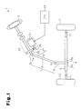
Fig. 1 is a schematic diagram showing an electric power steering device; -
Fig. 2 is a cross-sectional view showing a motor ofFig. 1 ; -
Fig. 3 is a bottom view showing a stator ofFig. 2 ; -
Fig. 4 is a cross-sectional view showing the stator ofFig. 2 ; -
Fig. 5A is a side view showing a first insulator; -
Fig. 5B is a front view showing the first insulator; -
Fig. 6A is a bottom view showing a bus bar; -
Fig. 6B is a cross-sectional view taken alongline 6B-6B ofFig. 6A ; and -
Fig. 7 is a schematic diagram showing coil connections. - A preferred embodiment of a column-type electric power steering (EPS)
apparatus 1 according to the present invention will now be described with reference to the drawings. - Referring to
Fig. 1 , theEPS apparatus 1 includes a steering wheel 2 fixed to asteering shaft 3, which is connected by a rack-and-pinion mechanism 4 to arack shaft 5. Rotation of thesteering shaft 3 during a steering operation is converted to linear reciprocating movements of therack shaft 5 by the rack-and-pinion mechanism 4. Specifically, thesteering shaft 3 includes a column shaft 8, anintermediate shaft 9, and apinion shaft 10, which are coupled together byuniversal joints 7a and 7b.Pinion teeth 10a are formed at one end of thepinion shaft 10, andrack teeth 5a are formed on therack shaft 5. The rack-and-pinion mechanism 4 is formed by the mating of thepinion teeth 10a with therack teeth 5a. When thesteering shaft 3 is rotated, the linear reciprocating movements of therack shaft 5 are transmitted to knuckles (not shown) bytie rods 11 coupled to the two ends of therack shaft 5. This changes the steering angle of steeredwheels 12, that is, the travel direction of the vehicle. - The
EPS apparatus 1 includes anEPS actuator 22 and an electronic control unit (ECU) 23. TheEPS actuator 22 applies assist force to the steering system so as to assist steering operations, and theECU 23 controls the operation of theEPS actuator 22. TheEPS actuator 22 includes amotor 21, which functions as a drive source that generates the assist force for rotating thesteering shaft 3. - Specifically, the
EPS actuator 22 is a so-called column-type EPS actuator for applying assist force to the column shaft 8. Themotor 21 includes arotatable motor shaft 26, which is coupled to the column shaft 8 by areduction mechanism 24 so that themotor shaft 26 can drive the column shaft 8. Thereduction mechanism 24 includes areduction gear 25 fixed to the column shaft 8 and amotor gear 27 fixed to themotor shaft 26. Thegears motor 21 is reduced by thereduction mechanism 24 and transmitted to the column shaft 8. TheEPS actuator 22 applies the motor torque thereof on the steering system as the assist force. A so-called worm and wheel is used as thereduction mechanism 24 in the preferred embodiment. The ECU 23 supplies themotor 21 with drive power to control the rotation produced by themotor 21, that is, the operation of theEPS actuator 22. - The structure of the
motor 21 will now be described with reference toFigs. 2 to 7 . The upper and lower sides as viewed inFigs. 2 and4 are defined here as the upper and lower sides of themotor 21. Themotor 21 is a three-phase brushless motor having a field permanent magnet arranged on a rotor. - As shown in
Fig. 2 , themotor 21 includes acylindrical housing 31 and acylindrical end frame 32, which is fixed to thehousing 31. The upper side of thehousing 31 is closed, and the lower side of thehousing 31 defines an opening 31a. Theend frame 32 is fixed to thehousing 31 so as to close the opening 31a of thehousing 31. In the preferred embodiment, thehousing 31 is formed from a metal material having high thermal conductivity (e.g., aluminum alloy). Acylindrical stator 33 is fixed to an inner surface of thehousing 31. Arotor 34 is fixed to themotor shaft 26 and rotatably supported in thestator 33 bybearings housing 31 and the central part of theend frame 32. Aring magnet 37 facing thestator 33 is fixed to an outer surface of therotor 34. Thering magnet 37 has plural magnetic poles (ten in the preferred embodiment) arranged along the circumferential direction. - As shown in
Fig. 3 , thestator 33 includes astator core 38. Thestator core 38 includes acylinder 39 andteeth 40, which project radially inward from thecylinder 39. Thestator core 38 further includes a plurality of (twelve in the preferred embodiment)core segments 41 arranged in the circumferential direction, with eachcore segment 41 including one of theteeth 40. Eachcore segment 41 is formed by stacking a plurality of core sheets (not shown). Each core sheet is obtained by punching out a magnetic metal plate. - As shown in
Fig. 4 , afirst insulator 51 and asecond insulator 52, which form a pair, is attached to eachcore segment 41. Specifically, eachfirst insulator 51 is attached to thecorresponding core segment 41 from the lower side of themotor 21, and eachsecond insulator 52 is attached to thecorresponding core segment 41 from the upper side of themotor 21. The first andsecond insulators - As shown in
Figs. 4, 5A, and 5B , eachfirst insulator 51 includes anend face cover 51a and two plate-shaped side surface covers 51b, which are integrally formed with theend face cover 51a and extend from two sides of theend face cover 51a. Theend face cover 51a covers the lower end face of thecorresponding core segment 41 andtooth 40. The side surface covers 51b cover the lower half of the two side surfaces of the correspondingtooth 40. Eachfirst insulator 51 further includes aninner restriction wall 51c and anouter restriction wall 51d. Theinner restriction wall 51c is formed integrally with a radially inward end of theend face cover 51a and extends to the lower side of themotor 21. Theouter restriction wall 51d is formed integrally with a radially outward end of theend face cover 51a and extends in the axial direction. - As shown in
Fig. 4 , in the same manner as thefirst insulator 51, eachsecond insulator 52 has anend face cover 52a and two plate-shaped side surface covers 52b, which are formed integrally with theend face cover 52a and extend from two sides of theend face cover 52a. Theend face cover 52a covers the upper end face of thecorresponding core segment 41 andtooth 40. The side surface covers 52b cover the upper half of the two side surfaces of the correspondingtooth 40. Eachsecond insulator 52 further includes aninner restriction wall 52c and anouter restriction wall 52d. Theinner restriction wall 52c is formed integrally with a radially inward end of theend face cover 52a and extends to the upper side of themotor 21. Theouter restriction wall 52d is formed integrally with a radially outward end of theend face cover 52a and extends in the axial direction. - Referring again to
Fig. 3 , twelvecoils 43 are formed by winding theconductive wire 42 onto the first andsecond insulators tooth 40 of thestator core 38, so as to form a concentrated winding. Theinner restriction walls coil 43. Theouter restriction walls coil 43. Theconductive wire 42 forming eachcoil 43 is coated by an insulative coating film. However, the insulative coating film is removed from predetermined regions at theends 44 of eachcoil 43. Thestator 33 is shrinkfitted and fixed to the inner surface of thehousing 31. - The
first insulator 51 will be now described below in detail with reference toFigs. 5A and 5B . - As shown in
Figs. 5A and 5B , eachfirst insulator 51 includes asupport 53 formed on theouter restriction wall 51d and extending in the axial direction. Thesupport 53 supports first to third arcuate bus bars 61 to 63 (Figs. 3 ,4 ,6 ). The first to third bus bars 61 to 63 each connect theends 44 of thecoils 43 that are supplied with current of the same phase. Eachsupport 53 includes aninner wall 54, anouter wall 55, and apartition wall 56. The inner andouter walls partition wall 56 in the radial direction. Further, theinner wall 54 and theouter wall 55 are spaced from thepartition wall 56 by predetermined intervals. Theinner wall 54, theouter wall 55, and thepartition wall 56 form a holdingslot 57 extending along the circumferential direction. The holdingslot 57 has an opening at the distal side (upper side as viewed inFig. 5A ) of thesupport 53. In the preferred embodiment, the holdingslot 57 is formed by two concentric grooves including aninner groove 57a, which is formed at the radially inward side, and anouter groove 57b, which is formed on the radially outward side. - An
engagement cavity 56a, which serves as a recess, is formed in the radially inner side of theouter groove 57b, that is, in the middle of thepartition wall 56. Theengagement cavity 56a extends in the axial direction from the lower end of theouter restriction wall 51d (upper side of the motor 21) to the middle of thepartition wall 56 and extends through thepartition wall 56 in the radial direction. Anengagement groove 54a, which serves as a recess, is formed in the radially inner side of theinner groove 57a, that is, in the middle of theinner wall 54. Theengagement groove 54a extends in the axial direction from the lower end of theouter restriction wall 51d (upper side of motor 21) to the vicinity of the distal end of theinner wall 54. Theengagement cavity 56a and theengagement groove 54a face each other. - The first to third bus bars 61 to 63 will now be described.
- As shown in
Fig. 6A , the first to third bus bars 61 to 63 each include amain portion 71 and first andsecond connection portions main portion 71 is formed from a strip of a conductive plate material. The first andsecond connection portions main portion 71. Themain portion 71 is bent so that a plurality of straight portions extend along an arc. Themain portion 71 is supported by the first insulators 51 (Fig. 3 ) in a state in which the widthwise direction of themain portion 71 is parallel to an axis L (Fig. 2 ). - As shown in
Fig. 6A , thefirst bus bar 61 includes themain portion 71, which is arcuate and extends along the circumferential direction at a lower side as viewed inFig. 6A , and a terminal 74, which is arranged at the basal end of themain portion 71. Thesecond bus bar 62 includes themain portion 71, which is arcuate and extends along the circumferential direction, and a terminal 74, which is arranged at the basal end of themain portion 71. Thethird bus bar 63 includes themain portion 71, which is arcuate and extends along the circumferential direction, and a terminal 74, which is arranged at an intermediate portion in the circumferential direction of themain portion 71. Themain portions 71 of the first to third bus bars 61, 62, and 63 are spaced at intervals from one another in the radial direction. Themain portions 71 are each arranged in correspondence with the locations of theends 44 of the corresponding coil 43 (seeFig. 3 ). Current is supplied to each coil 43 (seeFig. 3 ) by electrically connecting the terminal 74 to theECU 23, which is located outside themotor 21. - As shown in
Fig. 4 , themain portion 71 of each of the first to third bus bars 61 to 63 are held in the correspondinginner grooves 57a orouter grooves 57b of thefirst insulators 51. The first to third bus bars 61 to 63 are thus supported by thefirst insulators 51 in a state in which themain portions 71 are exposed. Specifically, themain portion 71 of thefirst bus bar 61 has a basal side held in theouter grooves 57b and a distal side held in theinner grooves 57a, as shown inFig. 3 . Themain portion 71 of thesecond bus bar 62 is entirely held in theouter groove 57b. The first and second bus bars 61 and 62 have distal portions that are overlapped with each other in the radial direction. Themain portion 71 of thethird bus bar 63 is entirely held in theinner grooves 57a and overlaps themain portions 71 of the first and second bus bars 61 and 62 in the radial direction. - As shown in
Fig. 6B , eachmain portion 71 includes a plurality ofstoppers 75 formed at locations corresponding to theinner grooves 57a and theouter grooves 57b. Eachstopper 75 is inclined by a predetermined angle with respect to the axial direction and projected radially inward (leftward as viewed inFig. 6B ). In the preferred embodiment, thestopper 75 is formed by performing cut and erection in which themain portion 71 is cut out and bent. Thestoppers 75 are formed at three locations in eachmain portion 71. At the part of themain portion 71 held in theouter grooves 57b of thefirst insulators 51, eachstopper 75 is fitted into thecorresponding engagement cavity 56a. At the part of themain portion 71 held in theinner grooves 57a, eachstopper 75 is fitted into thecorresponding engagement groove 54a. - As shown in
Fig. 6A , thefirst connection portions 72 are arranged at predetermined positions (two locations in eachmain portion 71 in the preferred embodiment) in the circumferential direction for eachmain portion 71. Thesecond connection portion 73 is arranged at a predetermined position (one location in eachmain portion 71 in the preferred embodiment) in the circumferential direction for eachmain portion 71. Eachfirst connection portion 72 is connected to oneend 44 of the correspondingcoil 43. Eachsecond connection portion 73 is connected to two ends 44 of the two correspondingcoils 43. Thefirst connection portion 72 each includes a first extension 76 (seeFig. 4 ), which extends to the lower side of themotor 21 from themain portion 71, and afirst holder 77, which extends radially inward from thefirst extension 76. In the same manner, thesecond connection portion 73 includes a second extension 78 (seeFig. 4 ), which extends to the lower side of themotor 21 from themain portion 71, and asecond holder 79, which extends radially inward from thesecond extension 78. The first andsecond connection portions main portion 71 are arranged so that they do not overlap one another in the circumferential direction. - In the preferred embodiment, the first and
second holders second holders second holders main portion 71 and supported by theouter grooves 57b are arranged radially inward from theinner groove 57a. Furthermore, the first andsecond holders Fig. 3 , thesecond holder 79 has a circumferential length that is longer than that of thefirst holder 77 to hold two ends 44. The ends 44 of eachcoil 43 are held in the predetermined ones of first andsecond holders second holders ends 44 of thecoils 43 are electrically connected through resistance welding. - As shown in
Fig. 7 , in the preferred embodiment, the ends 44 of thecoils 43 supplied with U-phase current are connected to one another by thefirst bus bar 61. The ends 44 of thecoils 43 supplied with V-phase current are connected to one another by thesecond bus bar 62. The ends 44 of thecoils 43 supplied with W-phase current are connected to one another by thethird bus bar 63. The two associatedcoils 43 connected by each of the first to third bus bars 61 to 63 are connected in series by a connection line so that the twoconnected coils 43 form a continuous winding. Further, two continuous windings are connected in parallel. In other words, six of the twelvecoils 43 form continuous windings are formed, and two sets of three continuous windings are delta-connected with the first to third bus bars 61 to 63 to form a double delta connection (parallel delta connection). - Referring to
Fig. 2 , a rotary magnetic field is formed around thering magnet 37 by supplying a three-phase alternating current to eachcoil 43. The rotary magnetic field and field magnetic flux generated by thering magnet 37 cooperate to rotate therotor 34 and thereby drive themotor 21. - In the preferred embodiment, the
motor 21 has the advantages described below. - (1) The
motor 21 includes thestator 33, which is formed by thestator core 38 having theteeth 40, which project radially inward, and thecoils 43, each formed by winding theconductive wire 42 onto the correspondingtooth 40 with the first andsecond insulators first insulators 51 each include thesupport 53 extending in the axial direction from the axial end of theouter restriction wall 51d. Thesupport 53 supports the first to third bus bars 61 to 63 in a state in which themain portions 71 are exposed. Themain portions 71 of the first to third bus bars 61 to 63 are thus in contact with ambient air. Thus, themain portions 71 are in direct contact with the ambient air, whereas a bus bar for a prior art motor is embedded in the resin bus bar holder Japanese Laid-Open Patent Publication No.2006-296147 coil 43 is easily radiated from the first to third bus bars 61 to 63. Since exclusive a bus bar holder does not need to be arranged in thehousing 31, the heat generated by thecoils 43 is easily radiated and released outside. This improves the heat radiation characteristics of themotor 21. - (2) The
support 53 extends in the axial direction from eachouter restriction wall 51d. This avoids enlargement of themotor 21 in the radial direction. - (3) The
main portion 71 in each of the first to third bus bars 61 to 63 is strip-shaped. Further, in thesupport 53, the distal side of theouter restriction wall 51d includes an opening, and theinner groove 57a and theouter groove 57b extend along the circumferential direction. Thus, the first to third bus bars 61 to 63 are easily supported by thefirst insulator 51 by holding the strip-shapedmain portions 71 with theinner grooves 57a and theouter grooves 57b. This facilitates the attachment of the first to third bus bars 61 to 63. - (4) The
stoppers 75 are each formed by cutting out themain portion 71 and bending the cut portion, which is fitted into thecorresponding engagement cavity 56a orengagement groove 54a of thefirst insulator 51. This easily fastens the first to third bus bars 61 to 63 to thefirst insulator 51. - (5) The
inner grooves 57a andouter grooves 57b are formed in two rows in the radial direction of thesupport 53. Compared to when forming three or more rows of holding slots in the radial direction, a longer radial distance between bus bars can be provided. This facilitates the radiation of heat from the first to third bus bars 61 to 63 and improves the heat radiation characteristics of themotor 21. - (6) The
main portion 71 of thefirst bus bar 61 has a basal side held in theouter grooves 57b and a distal side held in theinner grooves 57a. In this manner, a single bus bar is supported along different circumferences (i.e., along theinner grooves 57a and theouter grooves 57b). Thus, at least three bus bars that are required to supply three-phase current is supported along two rows in the radial direction by the inner andouter grooves - (7) The first and
second holders ends 44 of thecoils 43 into the first andsecond holders conductive wires 42 to be easily connected to the first to third bus bars 61 to 63. - (8) The two ends 44 of a
coil 43 are connected to eachsecond connection portion 73. This reduces the procedures required to connect theends 44 of thecoil 43 compared to when connecting only oneend 44 of thecoil 43. - (9) The first and
second holders main portion 71 supported by theouter grooves 57b are arranged radially inward from theinner grooves 57a. Thus, the ends 44 of thecoils 43 held by the first andsecond holders outer grooves 57b do not contact radially inward sides of bus bars. This improves the reliability of themotor 21. - (10) The first and
second holders stator 33, the first andsecond holders ends 44 of thecoils 43 to the first andsecond holders - (11) The ends 44 of the
coils 43 are connected to the first andsecond connection portions ends 44 of thecoils 43 to the first andsecond connection portions - (12) The
stator 33 includes the plurality ofcore segments 41. This facilitates the winding of theconductive wires 42 to theteeth 40 and improves the space factor of the coil 43 (proportion of theconductive wire 42 occupying the cross-section of the coil 43) thereby increasing the output of themotor 21. - (13) The plurality of
coils 43 are delta-connected. Thus, a bus bar for connecting eachcoil 43 to a neutral point, as in a star connection, is unnecessary. Therefore, the number of bus bars supported by thefirst insulator 51 is less than a star connection. A small number of bus bars are arranged in the radial direction, and a long radial distance can be provided between the first to third bus bars 61 to 63. This easily radiates heat from the first to third bus bars 61 to 63. This improves the heat radiation characteristics of themotor 21. - (14) The electrical resistance of the
coils 43 is reduced since thecoils 43 are connected in parallel between the first to third bus bars 61 to 63. Thus, the current flowing to eachcoil 43 increases and enable themotor 21 to produce high-speed rotation compared to when thecoils 43 are connected in series for each of the phases U, V, and W. - (15) The
housing 31 is formed from a metal material having high thermal conductivity. Thus, the heat generated by thecoils 43 is effectively released out of thestator 33 and thehousing 31. This improves the heat radiation characteristics of themotor 21. - (16) Improvement in the heat radiation characteristics of the
motor 21 suppresses temperature increases in thecoils 43 wound around theteeth 40. Thus, the electrical resistance of theconductive wires 42 is prevented from being increased, and voltage drops in theconductive wire 42 are suppressed. Therefore, themotor 21 applies appropriate assist torque to the steering system even when performing sudden steering (high-speed steering) operations. This improves the steering feel during sudden steering operations. - The
motor 21 of the preferred embodiment may be modified in the following forms. - To fasten the first to third bus bars 61 to 63 to the
first insulators 51, themain portions 71 include thestoppers 75, and thesupport 53 of eachfirst insulator 51 includes theengagement cavity 56a or theengagement groove 54a, which serves as a recess. However, other structures may be employed to fasten the first to third bus bars 61 to 63 to thefirst insulators 51. Either one of an engagement projection and an engagement recess may be formed in themain portion 71, and the other one of the engagement projection and the engagement recess may be formed in thesupport 53. Such a structure also fastens themain portions 71 to thesupports 53. - In the preferred embodiment, the
engagement groove 54a, to which thestopper 75 is fitted, is formed in theinner groove 57a. However, instead of theengagement groove 54a, an engagement groove may be formed at the outer side of theouter groove 57b, that is, in theouter wall 55. In this case, thestopper 75 is formed extending radially outward to be fitted and fastened to the engagement groove at the outer side of theouter groove 57b. - In the preferred embodiment, the
stopper 75 of themain portion 71 is fitted to theengagement cavity 56a or theengagement groove 54a of thesupport 53 to fasten the first to third bus bars 61 to 63 to thefirst insulator 51. Instead, theinner grooves 57a and theouter grooves 57b may be formed to have a depth that is the same as the width of themain portions 71 so that themain portions 71 can be completely accommodated in theinner grooves 57a and theouter grooves 57b. Further, a flange extending in the radial direction may be formed at the distal end of thepartition walls 56 to close the openings of theinner grooves 57a and theouter grooves 57b. This fastens the first to third bus bars 61 to 63 held in theinner grooves 57a and theouter grooves 57b. - Each
main portion 71 is bent to be generally arcuate. However, the main portion may be curved along the circumferential direction to be truly arcuate. - The
support 53 is arranged on the outer side of eachfirst insulator 51. Instead, the support may be arranged on the inner side of eachfirst insulator 51. Specifically, thesupport 53 extends in the axial direction from theouter restriction wall 51d but may be arranged instead so to extend in the axial direction from theinner restriction wall 51c. - Two coils 43 are connected by a connection wire to form a continuous winding. Instead, three or more coils may be connected by a connection wire to form a continuous winding.
- In the preferred embodiment, the
coils 43 are connected in parallel between the first to third bus bars 61 to 63, and the parallel-connectedcoils 43 are connected in a so-called double delta connection. Instead, thecoils 43 may be connected in series in a delta connection without being connected in parallel between the first to third bus bars 61 to 63. - Furthermore, each
coil 43 is delta-connected but may be star-connected instead. Such a structure obtains a higher output with themotor 21 under the same conditions compared to when eachcoil 43 is delta-connected. - In the preferred embodiment, the insulative coating film is removed from predetermined regions at the
ends 44 of theconductive wires 42, and the first to third bus bars 61 to 63 are connected to thecoils 43 at such regions through resistance welding. Instead, without removing the coating from theends 44 of theconductive wires 42, fusing may be performed to connect thecoils 43 to the first to third bus bars 61 to 63 by melting and integrating the insulative coating film with theends 44 of theconductive wire 42. - In the preferred embodiment, the
stator core 38 includes the plurality ofcore segments 41. Eachcore segment 41 is formed by stacking core sheets obtained by punching out a magnetic metal plate. Instead, thestator core 38 may be formed by sintering magnetic powder. Further, thestator core 38 may be formed by a single body instead of being formed from a plurality ofcore segments 41. - In the preferred embodiment, the
main portion 71 of thefirst bus bar 61 is held in theouter grooves 57b at the basal side and held in theinner grooves 57a at the distal side. Instead, themain portion 71 of thebus bar 62 may be held in theouter grooves 57b at the basal side and held in theinner grooves 57a at the distal side. - In the preferred embodiment, U-phase current is supplied to the
first bus bar 61, V-phase current is supplied to thesecond bus bar 62, and W-phase current is supplied to thethird bus bar 63. Instead, U-phase to W-phase currents may be supplied to any one of the first to the third bus bars 61 to 63. - In the preferred embodiment, the
stator 33 of themotor 21 includes twelveteeth 40, and twelvecoils 43 are wound around theteeth 40 to form concentrated windings. However, the number of the teeth and coils may be changed as required. In this case, the number of the first to third bus bars 61 to 63, and the number of thefirst connection portions 72 are changed as required in accordance with the number of coils. - It should be apparent to those skilled in the art that the present invention may be embodied in many other specific forms without departing from the spirit or scope of the invention. Therefore, the present examples and embodiments are to be considered as illustrative and not restrictive, and the invention is not to be limited to the details given herein, but may be modified within the scope and equivalence of the appended claims.
- A
motor 21 includes acylindrical stator 33. Thestator 33 includes astator core 38 havingteeth 40, which project inwardly in the radial direction, and coils 43, which are formed by winding a conductive wire onto eachtooth 40 with first andsecond insulators first insulator 61 includes asupport 53 extending axially from anouter restriction wall 51d. Each of first to third bus bars 61, 62, 63 is supported by thesupport 53 of thefirst insulator 51 a state in which amain portion 71 is exposed. Themain portions 71 of the first to third bus bars 61, 62, 63 are thus in contact with ambient air.
Claims (16)
- A three-phase brushless motor comprising:a cylindrical housing (31) extending in an axial direction of the motor;a cylindrical stator (33) arranged in the housing (31), the stator (33) including a stator core (38) having a plurality of teeth (40) projecting radially inwardly therefrom;a plurality of coils (43) each wound about an associated one of the teeth (40) and having an end (44);an insulator (51) arranged between each tooth (40) and associated coil (43) which electrically insulates the tooth (40) from the associated coil (43); anda plurality of bus bars (61, 62, 63) which electrically connect the ends (44) of the plurality of coils (43) supplied with an external current having the same phase;wherein each of the bus bars (61, 62, 63) includes a main portion (71) and a connection portion (72, 73), in which the main portion (71) extends in a circumferential direction, and the connection portion (72, 73) is arranged at a predetermined position on the main portion (71) and connected to the end (44) of an associated one of the coils (43);
the brushless motor being characterized in that the insulator (51) includes a support (53) which supports at least one of the bus bars (61, 62, 63) in a state in which the main portion (71) of the bus bar (61, 62, 63) is exposed. - The brushless motor according to claim 1, characterized in that each of the teeth (40) includes opposite end surfaces facing the axial direction of the motor;
the insulator (51) further includes an end cover (51a) and an outer restriction wall (51d), in which the end cover covers one of the end surfaces of the associated tooth (40), and the outer restriction wall (51d) extends in the axial direction at an outer side of the end cover (51a); and
the support (53) extends from the outer restriction wall (51d) in the axial direction of the motor. - The brushless motor according to claim 2, characterized in that the support (53) includes a holding slot (57) extending in the circumferential direction and an opening located at a distal side of the outer restriction wall (51d) in the axial direction of the motor; and
the main portion (71) of each of the bus bars (61, 62, 63) is strip-shaped and supported by the associated bus bar (61, 62, 63) such that a widthwise direction of the main portion (71) extends in the axial direction of the motor. - The brushless motor according to claim 3, characterized in that either one of the main portion (71) and the holding slot (57) includes an engaging projection (75), and the other of the main portion (71) and the holding slot (57) includes an engaging recess (56a) which is engageable with the engaging projection (75).
- The brushless motor according to claim 3, characterized in that the main portion (71) includes a stopper (75) inclined at a predetermined angle relative to the axial direction of the motor; and
the holding slot (57) includes a recess (56a) which is engageable with the stopper (75). - The brushless motor according to claim 3, characterized in that the holding slot (57) includes an inner groove (57a) formed at a radially inward side and an outer groove (57b) formed at a radially outward side, in which the inner and outer grooves (57a, 57b) are concentric.
- The brushless motor according to any one of claims 1 to 6, characterized in that the plurality of bus bars (61, 62, 63) includes:a first bus bar (61) having a basal end, which defines a terminal (74) supplied with the external current, and the main portion (71), which extends from the basal end in the circumferential direction;a second bus bar (62) having a basal end, which defines a terminal (74) supplied with the external current, and the main portion (71), which extends from the basal end in a direction opposite the first bus bar (61); anda third bus bar (63) having a basal end, which defines a terminal (74) supplied with the external current, and the main portion (71), which extends from the basal end in the circumferential direction and radially overlaps either one of the first and second bus bars (61, 62);the main portion (71) of one of the first and second bus bars (61, 62) includes a basal side and a distal side, in which the main portion (71) is held in the outer groove (57b) from the basal side to the distal side;
the main portion (71) of the other of the first and second bus bars (61, 62) includes a basal side and a distal side, in which the basal side is held in the outer groove (57b) and the distal side is held in the inner groove (57a); and
the main portions (71) of the first and second bus bars (61, 62) are radially overlapped with the main portion (71) of the third bus bar (63) at the basal sides and radially overlapped with each other at the distal sides. - The brushless motor according to any one of claims 1 to 7, characterized in that the connection portion (72, 73) of each of the bas bars (61, 62, 63) includes:an extension (76, 78) extending from a predetermined position of the main portion (71) in the axial direction of the motor; anda holder (77, 79) formed radially inward from the extension (76, 78), in which the holder (77, 79) has an opening which opens along the circumferential direction.
- The brushless motor according to claim 8, characterized in that the holders (77, 79) of the first and the second bus bars (61, 62) held in the associated outer grooves (57b) are located radially inward from the corresponding inner grooves (57a).
- The brushless motor according to claim 9, characterized in that the holders (77, 79) of the first, second, and third bus bars (61, 62, 63) are concentric.
- The brushless motor according to any one of claims 1 to 10, characterized in that the ends (44) of the coils (43) are welded and connected to the connection portions (72, 73) of the bus bars (61, 62, 63).
- The brushless motor according to any one of claims 1 to 11, characterized in that the stator core (38) includes a plurality of core segments (41) aligned along an inner surface of the housing (31).
- The brushless motor according to any one of claims 1 to 12, characterized in that the plurality of coils (43) are delta-connected.
- The brushless motor according to claim 13, characterized in that the coils (43) are parallel-connected between the bus bars (61, 62, 63) that are supplied with current having the same phase.
- The brushless motor according to any one of claims 1 to 14, characterized in that the housing (31) is formed from a metal having a high heat conductivity.
- An electric power steering apparatus comprising:the brushless motor according to any one of claims 1 to 15.
Applications Claiming Priority (1)
| Application Number | Priority Date | Filing Date | Title |
|---|---|---|---|
| JP2007224186A JP5256669B2 (en) | 2007-08-30 | 2007-08-30 | Brushless motor and electric power steering device |
Publications (3)
| Publication Number | Publication Date |
|---|---|
| EP2031736A2 true EP2031736A2 (en) | 2009-03-04 |
| EP2031736A3 EP2031736A3 (en) | 2013-05-01 |
| EP2031736B1 EP2031736B1 (en) | 2016-03-23 |
Family
ID=40091995
Family Applications (1)
| Application Number | Title | Priority Date | Filing Date |
|---|---|---|---|
| EP08162946.1A Ceased EP2031736B1 (en) | 2007-08-30 | 2008-08-26 | Brushless motor and electric power steering apparatus |
Country Status (3)
| Country | Link |
|---|---|
| US (1) | US8193677B2 (en) |
| EP (1) | EP2031736B1 (en) |
| JP (1) | JP5256669B2 (en) |
Cited By (4)
| Publication number | Priority date | Publication date | Assignee | Title |
|---|---|---|---|---|
| EP2768122A3 (en) * | 2010-06-14 | 2015-10-14 | Black & Decker Inc. | Stator assembly for a brushless motor in a power tool |
| US10523080B2 (en) | 2010-06-14 | 2019-12-31 | Black & Decker Inc. | Stator assembly for a brushless motor in a power tool |
| EP3598615A1 (en) * | 2018-07-17 | 2020-01-22 | Jtekt Corporation | Motor device |
| WO2026082241A1 (en) * | 2024-10-14 | 2026-04-23 | Schaeffler Technologies AG & Co. KG | Stator and method for producing a stator |
Families Citing this family (29)
| Publication number | Priority date | Publication date | Assignee | Title |
|---|---|---|---|---|
| JP4941007B2 (en) * | 2007-03-01 | 2012-05-30 | 日本電産株式会社 | motor |
| JP4972170B2 (en) * | 2007-11-09 | 2012-07-11 | 三菱電機株式会社 | Stator for rotating electric machine and method for manufacturing the same |
| JP4924595B2 (en) * | 2008-12-09 | 2012-04-25 | 日産自動車株式会社 | Concentrated power distribution member for concentrated winding motor |
| JP5614875B2 (en) * | 2010-01-20 | 2014-10-29 | 株式会社パイオラックス | Bus bar |
| DE102010033699B4 (en) * | 2010-07-30 | 2020-10-29 | Stöber Antriebstechnik GmbH & Co. KG | Switching head for electric motors and a method for connecting a switching head to the connecting strands of an electric motor winding |
| JP5672510B2 (en) * | 2012-06-01 | 2015-02-18 | 株式会社デンソー | Brushless motor and fuel pump using the same |
| JP6098920B2 (en) * | 2012-10-19 | 2017-03-22 | 日本電産株式会社 | Stator unit and motor |
| JP5929715B2 (en) * | 2012-11-09 | 2016-06-08 | 日立金属株式会社 | Power collection and distribution ring and electric motor |
| JP6135982B2 (en) * | 2013-01-17 | 2017-05-31 | 日本電産株式会社 | motor |
| WO2014171006A1 (en) * | 2013-04-19 | 2014-10-23 | 三菱電機株式会社 | Dynamo-electric machine |
| JP6234128B2 (en) | 2013-09-11 | 2017-11-22 | 株式会社マキタ | Electric tool |
| JP6125385B2 (en) * | 2013-09-17 | 2017-05-10 | 愛三工業株式会社 | Stator terminal |
| DE102014003873A1 (en) * | 2014-03-19 | 2015-09-24 | Minebea Co., Ltd. | stator |
| JP5955927B2 (en) * | 2014-11-21 | 2016-07-20 | 株式会社マキタ | Electric tool |
| DE102015225088A1 (en) | 2014-12-26 | 2016-06-30 | Nidec Corporation | Engine and method of making same |
| KR102388468B1 (en) | 2015-05-28 | 2022-04-20 | 엘지이노텍 주식회사 | Stator and motor using the same |
| JP6750451B2 (en) * | 2016-10-20 | 2020-09-02 | アイシン精機株式会社 | Brushless motor stator, brushless motor, and power slide door device using the brushless motor |
| JP6834479B2 (en) * | 2016-12-28 | 2021-02-24 | 日本電産株式会社 | motor |
| TWI606676B (en) | 2017-01-06 | 2017-11-21 | 群光電能科技股份有限公司 | Fixing device for junction wires of stator of motor |
| JP2018125950A (en) * | 2017-01-31 | 2018-08-09 | 日本電産株式会社 | Motor and air blowing device with the same |
| JP2018125951A (en) * | 2017-01-31 | 2018-08-09 | 日本電産株式会社 | Motor and air blowing device with the same |
| US11081870B2 (en) * | 2017-03-03 | 2021-08-03 | Nidec Corporation | Bus bar unit, motor, electric power steering device |
| JP7160031B2 (en) * | 2017-03-31 | 2022-10-25 | 日本電産株式会社 | motor |
| WO2018180641A1 (en) * | 2017-03-31 | 2018-10-04 | 日本電産株式会社 | Motor |
| DE112018002325T5 (en) | 2017-06-14 | 2020-01-23 | Makita Corporation | POWER TOOL |
| WO2020113056A1 (en) | 2018-11-29 | 2020-06-04 | Milwaukee Electric Tool Corporation | Motor winding design for an electric motor |
| JP7210261B2 (en) | 2018-12-14 | 2023-01-23 | 株式会社マキタ | ELECTRIC WORKING MACHINE AND METHOD FOR MANUFACTURING STATOR IN MOTOR FOR ELECTRIC WORKING MACHINE |
| KR102336674B1 (en) * | 2020-05-18 | 2021-12-07 | 현대모비스 주식회사 | Stator of motor for automobile |
| US12556055B2 (en) | 2022-01-24 | 2026-02-17 | Techtronic Cordless Gp | Electrical interconnector and motor including the same |
Citations (3)
| Publication number | Priority date | Publication date | Assignee | Title |
|---|---|---|---|---|
| JP2002330565A (en) | 2001-05-01 | 2002-11-15 | Aichi Emerson Electric Co Ltd | Motor stator and method of manufacturing the same |
| JP2006333666A (en) | 2005-05-27 | 2006-12-07 | Showa Corp | Rotating electric machine |
| JP2007068314A (en) | 2005-08-30 | 2007-03-15 | Showa Corp | Rotating electric machine |
Family Cites Families (14)
| Publication number | Priority date | Publication date | Assignee | Title |
|---|---|---|---|---|
| DE19544830A1 (en) * | 1995-12-01 | 1997-06-05 | Mulfingen Elektrobau Ebm | Stator for electric motors |
| JPH1118331A (en) * | 1997-06-30 | 1999-01-22 | Matsushita Electric Ind Co Ltd | Motor stator |
| JP3733316B2 (en) * | 2001-10-26 | 2006-01-11 | 住友電装株式会社 | Centralized power distribution member for thin brushless motor for vehicles |
| JP3733312B2 (en) * | 2001-10-26 | 2006-01-11 | 住友電装株式会社 | Manufacturing method of bus bar used for concentrated power distribution member of thin brushless motor for vehicle |
| JP3613262B2 (en) * | 2002-04-26 | 2005-01-26 | 三菱電機株式会社 | Rotating electric machine and manufacturing method thereof |
| JP4007176B2 (en) * | 2002-12-09 | 2007-11-14 | 株式会社日立製作所 | Rotating electric machine and wiring member |
| JP4350972B2 (en) * | 2003-05-08 | 2009-10-28 | ヤマハモーターエレクトロニクス株式会社 | Rotating machine armature |
| JP2005143247A (en) * | 2003-11-07 | 2005-06-02 | Asmo Co Ltd | Brushless motor, electric fan device, and method for manufacturing brushless motor |
| JP4483480B2 (en) * | 2004-08-27 | 2010-06-16 | アイシン精機株式会社 | Stator and motor |
| JP4549813B2 (en) * | 2004-11-04 | 2010-09-22 | アスモ株式会社 | Stator and brushless motor |
| JP4783012B2 (en) * | 2004-12-28 | 2011-09-28 | 日立オートモティブシステムズ株式会社 | Electric power steering motor and manufacturing method thereof |
| JP4697403B2 (en) | 2005-04-14 | 2011-06-08 | 株式会社ジェイテクト | Motor with connector |
| JP5176283B2 (en) * | 2006-03-30 | 2013-04-03 | 日産自動車株式会社 | Rotating electrical machine bus bar insulation structure |
| JP5217117B2 (en) * | 2006-06-05 | 2013-06-19 | 日本電産株式会社 | Brushless motor |
-
2007
- 2007-08-30 JP JP2007224186A patent/JP5256669B2/en not_active Expired - Fee Related
-
2008
- 2008-08-26 EP EP08162946.1A patent/EP2031736B1/en not_active Ceased
- 2008-08-27 US US12/199,033 patent/US8193677B2/en not_active Expired - Fee Related
Patent Citations (3)
| Publication number | Priority date | Publication date | Assignee | Title |
|---|---|---|---|---|
| JP2002330565A (en) | 2001-05-01 | 2002-11-15 | Aichi Emerson Electric Co Ltd | Motor stator and method of manufacturing the same |
| JP2006333666A (en) | 2005-05-27 | 2006-12-07 | Showa Corp | Rotating electric machine |
| JP2007068314A (en) | 2005-08-30 | 2007-03-15 | Showa Corp | Rotating electric machine |
Cited By (8)
| Publication number | Priority date | Publication date | Assignee | Title |
|---|---|---|---|---|
| EP2768122A3 (en) * | 2010-06-14 | 2015-10-14 | Black & Decker Inc. | Stator assembly for a brushless motor in a power tool |
| US10056806B2 (en) | 2010-06-14 | 2018-08-21 | Black & Decker Inc. | Stator assembly for a brushless motor in a power tool |
| US10523080B2 (en) | 2010-06-14 | 2019-12-31 | Black & Decker Inc. | Stator assembly for a brushless motor in a power tool |
| US11128194B2 (en) | 2010-06-14 | 2021-09-21 | Black & Decker Inc. | Stator assembly for a brushless motor in a power tool |
| EP3598615A1 (en) * | 2018-07-17 | 2020-01-22 | Jtekt Corporation | Motor device |
| CN110723199A (en) * | 2018-07-17 | 2020-01-24 | 株式会社捷太格特 | Motor device |
| US11171538B2 (en) | 2018-07-17 | 2021-11-09 | Jtekt Corporation | Motor device |
| WO2026082241A1 (en) * | 2024-10-14 | 2026-04-23 | Schaeffler Technologies AG & Co. KG | Stator and method for producing a stator |
Also Published As
| Publication number | Publication date |
|---|---|
| US20090058215A1 (en) | 2009-03-05 |
| JP2009056867A (en) | 2009-03-19 |
| EP2031736B1 (en) | 2016-03-23 |
| JP5256669B2 (en) | 2013-08-07 |
| EP2031736A3 (en) | 2013-05-01 |
| US8193677B2 (en) | 2012-06-05 |
Similar Documents
| Publication | Publication Date | Title |
|---|---|---|
| EP2031736B1 (en) | Brushless motor and electric power steering apparatus | |
| CN110546862B (en) | Bus bar unit and motor having the same | |
| JP4783012B2 (en) | Electric power steering motor and manufacturing method thereof | |
| US7312545B2 (en) | Controller for electric power steering and electric power steering system | |
| CN110476331B (en) | Bus bar unit and motor having the same | |
| JP6349933B2 (en) | Electric motor, electric power steering device, and vehicle | |
| US7242128B2 (en) | DC brushless motor for electrical power steering and the production method thereof | |
| JP5847543B2 (en) | Busbar unit and brushless motor | |
| JP5460095B2 (en) | Brushless motor | |
| JP5028220B2 (en) | Electric power steering motor, electromagnetic shield structure and electromagnetic shield method used therefor | |
| US8106550B2 (en) | Polyphase alternating-current motor and electric power steering apparatus | |
| JP2007202263A (en) | Electric power steering motor | |
| CN101562373A (en) | Electric power collection/distribution ring of rotary electric machine | |
| EP3556532B1 (en) | Molded body | |
| JP6706583B2 (en) | Brushless motor | |
| US20180175570A1 (en) | Bus bar unit and rotary electric machine having the same | |
| JP2011182511A (en) | Rotary electric machine, rotary electric machine for electric power steering devices using the same, and electric power steering device | |
| CN114287095B (en) | Motor | |
| JP5773963B2 (en) | Electric motor stator and electric motor | |
| JP7262585B2 (en) | Electric drive device and electric power steering device | |
| JP2007082315A (en) | Electric power steering motor and control device therefor | |
| JP2021093780A (en) | Rotary electric machine | |
| JP2022515053A (en) | motor | |
| JP2008148457A (en) | Connection structure for resolver and brushless motor |
Legal Events
| Date | Code | Title | Description |
|---|---|---|---|
| PUAI | Public reference made under article 153(3) epc to a published international application that has entered the european phase |
Free format text: ORIGINAL CODE: 0009012 |
|
| AK | Designated contracting states |
Kind code of ref document: A2 Designated state(s): AT BE BG CH CY CZ DE DK EE ES FI FR GB GR HR HU IE IS IT LI LT LU LV MC MT NL NO PL PT RO SE SI SK TR |
|
| AX | Request for extension of the european patent |
Extension state: AL BA MK RS |
|
| PUAL | Search report despatched |
Free format text: ORIGINAL CODE: 0009013 |
|
| AK | Designated contracting states |
Kind code of ref document: A3 Designated state(s): AT BE BG CH CY CZ DE DK EE ES FI FR GB GR HR HU IE IS IT LI LT LU LV MC MT NL NO PL PT RO SE SI SK TR |
|
| AX | Request for extension of the european patent |
Extension state: AL BA MK RS |
|
| RIC1 | Information provided on ipc code assigned before grant |
Ipc: H02K 3/52 20060101AFI20130328BHEP |
|
| 17P | Request for examination filed |
Effective date: 20131023 |
|
| RBV | Designated contracting states (corrected) |
Designated state(s): AT BE BG CH CY CZ DE DK EE ES FI FR GB GR HR HU IE IS IT LI LT LU LV MC MT NL NO PL PT RO SE SI SK TR |
|
| AKX | Designation fees paid |
Designated state(s): DE FR |
|
| 17Q | First examination report despatched |
Effective date: 20140116 |
|
| GRAP | Despatch of communication of intention to grant a patent |
Free format text: ORIGINAL CODE: EPIDOSNIGR1 |
|
| INTG | Intention to grant announced |
Effective date: 20150925 |
|
| GRAS | Grant fee paid |
Free format text: ORIGINAL CODE: EPIDOSNIGR3 |
|
| GRAA | (expected) grant |
Free format text: ORIGINAL CODE: 0009210 |
|
| RIN1 | Information on inventor provided before grant (corrected) |
Inventor name: NIWA, TOMOHIRO Inventor name: MURAKAMI, TOSHIAKI |
|
| AK | Designated contracting states |
Kind code of ref document: B1 Designated state(s): DE FR |
|
| REG | Reference to a national code |
Ref country code: DE Ref legal event code: R096 Ref document number: 602008043010 Country of ref document: DE |
|
| REG | Reference to a national code |
Ref country code: FR Ref legal event code: PLFP Year of fee payment: 9 |
|
| REG | Reference to a national code |
Ref country code: DE Ref legal event code: R097 Ref document number: 602008043010 Country of ref document: DE |
|
| PLBE | No opposition filed within time limit |
Free format text: ORIGINAL CODE: 0009261 |
|
| STAA | Information on the status of an ep patent application or granted ep patent |
Free format text: STATUS: NO OPPOSITION FILED WITHIN TIME LIMIT |
|
| 26N | No opposition filed |
Effective date: 20170102 |
|
| REG | Reference to a national code |
Ref country code: FR Ref legal event code: PLFP Year of fee payment: 10 |
|
| REG | Reference to a national code |
Ref country code: FR Ref legal event code: PLFP Year of fee payment: 11 |
|
| PGFP | Annual fee paid to national office [announced via postgrant information from national office to epo] |
Ref country code: FR Payment date: 20180712 Year of fee payment: 11 Ref country code: DE Payment date: 20180814 Year of fee payment: 11 |
|
| REG | Reference to a national code |
Ref country code: DE Ref legal event code: R119 Ref document number: 602008043010 Country of ref document: DE |
|
| PG25 | Lapsed in a contracting state [announced via postgrant information from national office to epo] |
Ref country code: FR Free format text: LAPSE BECAUSE OF NON-PAYMENT OF DUE FEES Effective date: 20190831 Ref country code: DE Free format text: LAPSE BECAUSE OF NON-PAYMENT OF DUE FEES Effective date: 20200303 |