EP2031470A2 - Systèmes et/ou dispositifs pour contrôler la synchronisation des cycles de diagnostic et de conversion de données pour des applications E/S redondantes - Google Patents
Systèmes et/ou dispositifs pour contrôler la synchronisation des cycles de diagnostic et de conversion de données pour des applications E/S redondantes Download PDFInfo
- Publication number
- EP2031470A2 EP2031470A2 EP08163336A EP08163336A EP2031470A2 EP 2031470 A2 EP2031470 A2 EP 2031470A2 EP 08163336 A EP08163336 A EP 08163336A EP 08163336 A EP08163336 A EP 08163336A EP 2031470 A2 EP2031470 A2 EP 2031470A2
- Authority
- EP
- European Patent Office
- Prior art keywords
- input module
- analog input
- module
- data conversion
- cycle
- Prior art date
- Legal status (The legal status is an assumption and is not a legal conclusion. Google has not performed a legal analysis and makes no representation as to the accuracy of the status listed.)
- Granted
Links
- 238000006243 chemical reaction Methods 0.000 title claims abstract description 38
- 230000000977 initiatory effect Effects 0.000 claims abstract description 17
- 238000000034 method Methods 0.000 claims description 31
- 238000004891 communication Methods 0.000 claims description 28
- 230000000694 effects Effects 0.000 description 34
- 230000006870 function Effects 0.000 description 12
- 230000008569 process Effects 0.000 description 12
- 230000015654 memory Effects 0.000 description 10
- 238000010586 diagram Methods 0.000 description 8
- 230000004044 response Effects 0.000 description 8
- 238000001514 detection method Methods 0.000 description 7
- 238000012546 transfer Methods 0.000 description 6
- 238000004519 manufacturing process Methods 0.000 description 5
- 230000003287 optical effect Effects 0.000 description 5
- 238000012545 processing Methods 0.000 description 5
- 230000001413 cellular effect Effects 0.000 description 4
- 230000033001 locomotion Effects 0.000 description 4
- 230000007246 mechanism Effects 0.000 description 4
- 230000000007 visual effect Effects 0.000 description 4
- 238000005259 measurement Methods 0.000 description 3
- 230000002441 reversible effect Effects 0.000 description 3
- 230000035807 sensation Effects 0.000 description 3
- 238000012163 sequencing technique Methods 0.000 description 3
- 230000001360 synchronised effect Effects 0.000 description 3
- 230000006378 damage Effects 0.000 description 2
- 230000004907 flux Effects 0.000 description 2
- 238000009432 framing Methods 0.000 description 2
- 230000014509 gene expression Effects 0.000 description 2
- 239000007943 implant Substances 0.000 description 2
- 239000000463 material Substances 0.000 description 2
- 238000012986 modification Methods 0.000 description 2
- 230000004048 modification Effects 0.000 description 2
- 230000008520 organization Effects 0.000 description 2
- 238000004886 process control Methods 0.000 description 2
- 238000009877 rendering Methods 0.000 description 2
- 239000000126 substance Substances 0.000 description 2
- 230000009466 transformation Effects 0.000 description 2
- 208000003251 Pruritus Diseases 0.000 description 1
- XUIMIQQOPSSXEZ-UHFFFAOYSA-N Silicon Chemical compound [Si] XUIMIQQOPSSXEZ-UHFFFAOYSA-N 0.000 description 1
- 208000027418 Wounds and injury Diseases 0.000 description 1
- 230000001133 acceleration Effects 0.000 description 1
- 230000009471 action Effects 0.000 description 1
- 238000013459 approach Methods 0.000 description 1
- 230000005540 biological transmission Effects 0.000 description 1
- 230000008859 change Effects 0.000 description 1
- 239000004020 conductor Substances 0.000 description 1
- 230000036461 convulsion Effects 0.000 description 1
- 230000008878 coupling Effects 0.000 description 1
- 238000010168 coupling process Methods 0.000 description 1
- 238000005859 coupling reaction Methods 0.000 description 1
- 230000003111 delayed effect Effects 0.000 description 1
- 238000013461 design Methods 0.000 description 1
- 238000006073 displacement reaction Methods 0.000 description 1
- 238000009826 distribution Methods 0.000 description 1
- 230000005484 gravity Effects 0.000 description 1
- 230000036039 immunity Effects 0.000 description 1
- 208000014674 injury Diseases 0.000 description 1
- 230000002427 irreversible effect Effects 0.000 description 1
- 230000003155 kinesthetic effect Effects 0.000 description 1
- 239000011159 matrix material Substances 0.000 description 1
- 229910052751 metal Inorganic materials 0.000 description 1
- 239000002184 metal Substances 0.000 description 1
- 150000002739 metals Chemical class 0.000 description 1
- 238000012544 monitoring process Methods 0.000 description 1
- 239000013307 optical fiber Substances 0.000 description 1
- 230000037361 pathway Effects 0.000 description 1
- 230000002093 peripheral effect Effects 0.000 description 1
- 230000035699 permeability Effects 0.000 description 1
- 230000010363 phase shift Effects 0.000 description 1
- 230000010287 polarization Effects 0.000 description 1
- 239000002244 precipitate Substances 0.000 description 1
- 238000002360 preparation method Methods 0.000 description 1
- 239000000047 product Substances 0.000 description 1
- 238000005070 sampling Methods 0.000 description 1
- 229910052710 silicon Inorganic materials 0.000 description 1
- 239000010703 silicon Substances 0.000 description 1
- 239000007858 starting material Substances 0.000 description 1
- 230000003068 static effect Effects 0.000 description 1
- 238000003860 storage Methods 0.000 description 1
- 230000001052 transient effect Effects 0.000 description 1
- 230000007704 transition Effects 0.000 description 1
- 238000002834 transmittance Methods 0.000 description 1
- 238000010200 validation analysis Methods 0.000 description 1
Images


Classifications
-
- G—PHYSICS
- G05—CONTROLLING; REGULATING
- G05B—CONTROL OR REGULATING SYSTEMS IN GENERAL; FUNCTIONAL ELEMENTS OF SUCH SYSTEMS; MONITORING OR TESTING ARRANGEMENTS FOR SUCH SYSTEMS OR ELEMENTS
- G05B19/00—Programme-control systems
- G05B19/02—Programme-control systems electric
- G05B19/04—Programme control other than numerical control, i.e. in sequence controllers or logic controllers
- G05B19/042—Programme control other than numerical control, i.e. in sequence controllers or logic controllers using digital processors
- G05B19/0421—Multiprocessor system
-
- G—PHYSICS
- G05—CONTROLLING; REGULATING
- G05B—CONTROL OR REGULATING SYSTEMS IN GENERAL; FUNCTIONAL ELEMENTS OF SUCH SYSTEMS; MONITORING OR TESTING ARRANGEMENTS FOR SUCH SYSTEMS OR ELEMENTS
- G05B2219/00—Program-control systems
- G05B2219/20—Pc systems
- G05B2219/22—Pc multi processor system
- G05B2219/2239—Reallocate, reschedule execution of controlled functions if one processor fails
-
- G—PHYSICS
- G05—CONTROLLING; REGULATING
- G05B—CONTROL OR REGULATING SYSTEMS IN GENERAL; FUNCTIONAL ELEMENTS OF SUCH SYSTEMS; MONITORING OR TESTING ARRANGEMENTS FOR SUCH SYSTEMS OR ELEMENTS
- G05B2219/00—Program-control systems
- G05B2219/20—Pc systems
- G05B2219/24—Pc safety
- G05B2219/24173—One sensor, two I-O channels each for different processor
-
- G—PHYSICS
- G05—CONTROLLING; REGULATING
- G05B—CONTROL OR REGULATING SYSTEMS IN GENERAL; FUNCTIONAL ELEMENTS OF SUCH SYSTEMS; MONITORING OR TESTING ARRANGEMENTS FOR SUCH SYSTEMS OR ELEMENTS
- G05B2219/00—Program-control systems
- G05B2219/20—Pc systems
- G05B2219/24—Pc safety
- G05B2219/24184—Redundant I-O, software comparison of both channels
-
- G—PHYSICS
- G05—CONTROLLING; REGULATING
- G05B—CONTROL OR REGULATING SYSTEMS IN GENERAL; FUNCTIONAL ELEMENTS OF SUCH SYSTEMS; MONITORING OR TESTING ARRANGEMENTS FOR SUCH SYSTEMS OR ELEMENTS
- G05B2219/00—Program-control systems
- G05B2219/20—Pc systems
- G05B2219/24—Pc safety
- G05B2219/24186—Redundant processors are synchronised
-
- G—PHYSICS
- G05—CONTROLLING; REGULATING
- G05B—CONTROL OR REGULATING SYSTEMS IN GENERAL; FUNCTIONAL ELEMENTS OF SUCH SYSTEMS; MONITORING OR TESTING ARRANGEMENTS FOR SUCH SYSTEMS OR ELEMENTS
- G05B2219/00—Program-control systems
- G05B2219/20—Pc systems
- G05B2219/24—Pc safety
- G05B2219/24187—Redundant processors run identical programs
-
- G—PHYSICS
- G06—COMPUTING; CALCULATING OR COUNTING
- G06F—ELECTRIC DIGITAL DATA PROCESSING
- G06F11/00—Error detection; Error correction; Monitoring
- G06F11/07—Responding to the occurrence of a fault, e.g. fault tolerance
- G06F11/16—Error detection or correction of the data by redundancy in hardware
- G06F11/1675—Temporal synchronisation or re-synchronisation of redundant processing components
Definitions
- Certain exemplary embodiments can provide a first analog input module adapted to, via a sent synchronization signal, automatically terminate a diagnostic cycle of a second analog input module.
- the synchronization signal can be adapted to cause an initiation of a data conversion cycle at the second analog input module.
- FIG. 1 is a block diagram of an exemplary embodiment of a system 1000
- FIG. 2 is a flowchart of an exemplary embodiment of a method 2000
- FIG. 3 is a flowchart of an exemplary embodiment of a method 3000
- FIG. 4 is a signal diagram of an exemplary embodiment of a method 4000
- FIG. 5 is a flowchart of an exemplary embodiment of a method 5000
- FIG. 6 is a block diagram of an exemplary embodiment of an information device 6000.
- Certain exemplary embodiments can provide a first analog input module adapted to, via a sent synchronization signal, automatically terminate a diagnostic cycle of a second analog input module.
- the synchronization signal can be adapted to cause an initiation of a data conversion cycle at the second analog input module.
- analog inputs with active wire-break detection cannot be used in a redundant application unless the wire-break detection circuit is disabled.
- External passive circuits have been used to provide wire-break detection at the expense of input accuracy.
- the diagnostic cycle and data conversion can be synchronized so that the wire-break detection circuit is enabled only during a predefined time and is turned off during the data conversion time.
- a synchronization pulse can be used to trigger the start of the process or can be used to frame the event times of the diagnostic cycle and the data conversion cycle.
- a message transfer to/from each module can be used in systems where the master/slave relationship can be defined and/or controlled.
- a simple synchronization pulse can be used to start the input processing cycle.
- the master module can run normally with an internal timer to control the input process and output a synchronization pulse to trigger the slave module to start the input process.
- FIG. 1 is a block diagram of an exemplary embodiment of a system 1000, which can comprise a programmable logic controller 1100.
- programmable logic controller 1100 can comprise and/or be communicatively coupled to a first input module 1200 and a second input module 1300.
- Each of first input module 1200 and second input module 1300 can be analog input modules.
- first input module 1200 and second input module 1200 can be communicatively coupled to a sensor 1250, such as a thermocouple.
- each of first input module 1200 and second input module 1200 can be communicatively coupled to a separate sensor to provide additional fault tolerance in system 1000.
- system 1000 can be adapted to define a master/slave relationship between first input module 1200 and second input module 1300.
- first input module 1200 can be adapted to:
- a diagnostic cycle which can be adapted to automatically detect a broken wire
- thermocouple initiates a data conversion cycle, which can be adapted to automatically obtain a temperature value from a thermocouple.
- Second analog input module 1300 can be adapted to:
- first analog input module 1200 can be adapted to, via a sent synchronization signal, automatically terminate a diagnostic cycle of second analog input module 1300.
- the synchronization signal can be adapted to cause an initiation of a data conversion cycle at second analog input module 1300.
- the synchronization signal can be sent subsequent to an acknowledged request to establish communication with second analog input module 1300.
- Programmable logic controller 1100 can be communicatively coupled to an information device 1500 via a network 1400.
- Information device 1500 can comprise and/or be communicatively coupled to a user interface 1520, a user program 1540, and a memory 1560.
- User program 1540 can be adapted to monitor and/or control one or more activities associated with programmable logic controller 1100 such as information transfers between programmable logic controller 1100 and/or first input module 1200 and/or second input module 1200.
- User interface 1520 can be adapted to render information regarding programmable logic controller 1100 such as information transfers between programmable logic controller 1100 and/or first input module 1200 and/or second input module 1200.
- Memory 1560 can be adapted to store and/or retrieve information regarding programmable logic controller 1100.
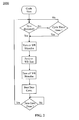
- FIG. 2 is a flowchart of an exemplary embodiment of a method 2000.
- the master/slave relationship can be predefined and might not be swapped due to a loss of the master module.
- the slave module if the slave module does not detect the synchronization pulse, the slave can continue to run on internal timers until a new synchronization pulse is detected from the master module.
- FIG. 3 is a flowchart of an exemplary embodiment of a method 3000.
- the synchronization pulse can be used as a framing signal to determine when the diagnostic cycle is to run and when the data conversion cycle is to run. For example, when the synchronization pulse is high, the diagnostic cycle can be enabled and when the synchronization pulse transitions low, the diagnostic cycle can be disabled and data conversion can begin.
- the master/slave relationship can be predefined in this solution and might not be swapped due to a loss of the master module. If the slave module does not detect the framing synchronization pulse, the slave module can continue to run on internal timers until a new synchronization pulse is detected from the master module.
- FIG. 4 is a signal diagram of an exemplary embodiment of a method 4000.
- the master/slave relationship can be controlled and/or swappable.
- a message transfer solution can be used to determine the master/slave relationship and/or control the diagnostic cycle and data conversion times.
- Communication can first be established at power-up. Module A can send a request to establish communication. If Module B is present, it can acknowledge this request. Upon receiving the acknowledgement from Module B that communication is established, Module A can request mastership and/or assume the role of master. Module B can acknowledge the request for mastership and assume the role of slave. If Module B is not present during the request to establish communication, Module A can assume mastership and continue to request to establish communication. After the mastership role is determined, the module cycle can be synchronized.
- Module A can send the start diagnostic cycle command. Upon completion of the diagnostic cycle, Module B can send the acknowledgement that the diagnostic cycle is complete. Module A can then send the start data conversion command. Again, upon completion of the data conversion cycle, Module B can send the acknowledgement that the data conversion cycle is complete. Module A can then repeat the process by sending the diagnostic cycle start again. If at any point Module A should be lost/removed, Module B might not receive the start command for a given cycle. An internal timer can timeout indicating to Module B that synchronization is lost and Module B can take over the mastership role and attempt to establish communication which Module A. When Module A can be reactivated or reinserted, it can acknowledge the request to establish communication and assume the role of slave.
- the physical connection between the two modules can be a single ended signal or a differential signal for increased noise immunity.
- Any available port pin can be used to send or receive the synchronization pulse.
- any available serial communication port can be used as the transfer mechanism for the message transfer solution.
- FIG. 5 is a flowchart of an exemplary embodiment of a method 5000.
- one or more activities of method 5000 can be performed automatically, such as via machine-implementable instructions stored on a machine-readable medium.
- communication can be established between a first module and a second module of a programmable logic controller and/or a programmable logic controller system.
- the first module and/or the second module can be analog input modules.
- the first module can be adapted to send to the second module a request to establish communication with the second module.
- the first module can be adapted to receive from the second module an acknowledgment of a request to establish communication between the first module and the second module.
- a relationship between the first module and the second module can be defined.
- Certain exemplary embodiments can define a master/slave relationship with respect to the second module.
- Certain exemplary embodiments can define a master/slave relationship between the first module and the second module.
- the first module can request and/or assume mastership with respect to the second module.
- the second module adapted to assume a slave role with respect to the first module.
- the second module can begin a diagnostic cycle.
- a signal from the first module can be adapted to cause an initiation of the diagnostic cycle.
- the first module can be adapted to receive a notification that the second module has assumed mastership with respect to the first module.
- the second module can detect and/or attempt to detect a broken wire associated with a sensor.
- the second module can be adapted to receive a synchronization signal.
- the first module can be adapted to output the synchronization signal, which can be a synchronization pulse, to the second module.
- the synchronization signal adapted to cause an initiation of a data conversion cycle at the second module.
- the synchronization signal can be sent subsequent to an acknowledged request to establish communication with the second module.
- the diagnostic cycle can be terminated.
- the synchronization signal which can be sent by the first module, can automatically cause a diagnostic cycle of the second module to terminate.
- the first module can be adapted to, upon completion of the diagnostic cycle, receiving an acknowledgment from the second module that the diagnostic cycle is complete.
- a data conversion cycle can begin.
- the data conversion cycle can begin automatically responsive to the synchronization signal.
- the first module can be adapted to receive a notification that the second module has assumed mastership with respect to the first module.
- the data conversion cycle can be adapted to automatically obtain a temperature value from a thermocouple.
- data can be outputted.
- the data can be temperature data obtained from a thermocouple.
- the data conversion cycle can be terminated.
- the data conversion cycle can be automatically terminated.
- the first module can be adapted to, upon completion of the data conversion cycle, receive an acknowledgment that the data conversion cycle is complete.
- FIG. 6 is a block diagram of an exemplary embodiment of an information device 6000, which in certain operative embodiments can comprise, for example, user information device 1500 of FIG. 1 .
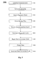
- Information device 6000 can comprise any of numerous circuits and/or components, such as for example, one or more network interfaces 6100, one or more processors 6200, one or more memories 6300 containing instructions 6400, one or more input/output (I/O) devices 6500, and/or one or more user interfaces 6600 coupled to I/O device 6500, etc.
- I/O input/output
- a user via one or more user interfaces 6600, such as a graphical user interface, a user can view a rendering of information related to researching, designing, modeling, creating, developing, building, manufacturing, operating, maintaining, storing, marketing, selling, delivering, selecting, specifying, requesting, ordering, receiving, returning, rating, and/or recommending any of the products, services, methods, and/or information described herein.
- analog - a signal formed from continuous measurement and/or input.
- apparatus an appliance and/or device for a particular purpose.
- associate - to relate bring together in a relationship, map, combine, join, and/or connect.
- an automatic light switch can turn on upon "seeing" a person in its view, without the person manually operating the light switch.
- circuit - an electrically conductive pathway and/or a communications connection established across two or more switching devices comprised by a network and between corresponding end systems connected to, but not comprised by the network.
- coupleable - capable of being joined, connected, and/or linked together.
- diagnostic cycle - a set of activities adapted to determine a failure of a device and/or system.
- haptic both the human sense of kinesthetic movement and the human sense of touch.
- many potential haptic experiences are numerous sensations, body-positional differences in sensations, and time-based changes in sensations that are perceived at least partially in non-visual, non-audible, and non-olfactory manners, including the experiences of tactile touch (being touched), active touch, grasping, pressure, friction, traction, slip, stretch, force, torque, impact, puncture, vibration, motion, acceleration, jerk, pulse, orientation, limb position, gravity, texture, gap, recess, viscosity, pain, itch, moisture, temperature, thermal conductivity, and thermal capacity.
- hard deadline the special case where completing an activity within the deadline results in the system receiving all the utility possible from that activity, and completing the activity outside of the deadline results in zero utility (i.e., resources consumed by the activity were wasted, such as when one travels to the beach to photograph a sunrise on a particular day and arrives after the sun has already arisen) or some negative value of utility (i.e., the activity was counter-productive, such as when firefighters enter a burning building to search for a missing person seconds before the building collapses, resulting in injury or death to the firefighters).
- the scheduling criterion for a hard deadline is to always meet the hard deadline, even if it means changing the activity to do so.
- hard real-time - relating to computer systems that provide an absolute deterministic response to an event. Such a response is not based on average event time. Instead, in such computer systems, the deadlines are fixed and the system must guarantee a response within a fixed and well-defined time.
- Systems operating in hard real-time typically interact at a low level with physical hardware via embedded systems, and can suffer a critical failure if time constraints are violated.
- a classic example of a hard real-time computing system is the anti-lock brakes on a car.
- the hard real-time constraint, or deadline, in this system is the time in which the brakes must be released to prevent the wheel from loclcing.
- Another example is a car engine control system, in which a delayed control signal might cause engine failure or damage.
- Other examples of hard real-time embedded systems include medical systems such as heart pacemakers and industrial process controllers.
- An information device any device on which resides a finite state machine capable of implementing at least a portion of a method, structure, and/or or graphical user interface described herein.
- An information device can comprise well-known communicatively coupled components, such as one or more network interfaces, one or more processors, one or more memories containing instructions, one or more input/output (I/O) devices, and/or one or more user interfaces (e.g., coupled to an I/O device) via which information can be rendered to implement one or more functions described herein.
- I/O input/output
- an information device can be any general purpose and/or special purpose computer, such as a personal computer, video game system (e.g., PlayStation, Nintendo Gameboy, X-Box, etc.), workstation, server, minicomputer, mainframe, supercomputer, computer terminal, laptop, wearable computer, and/or Personal Digital Assistant (PDA), iPod, mobile terminal, Bluetooth device, communicator, "smart" phone (such as a Tree-like device), messaging service (e.g., Blackberry) receiver, pager, facsimile, cellular telephone, a traditional telephone, telephonic device, a programmed microprocessor or microcontroller and/or peripheral integrated circuit elements, a digital signal processor, an ASIC or other integrated circuit, a hardware electronic logic circuit such as a discrete element circuit, and/or a programmable logic device such as a PLD, PLA, FPGA, or PAL, or the like, etc.
- PDA Personal Digital Assistant
- input module - a device and/or system adapted to receive information between a programmable logic controller (PLC) and a predetermined set of sensors and/or actuators.
- PLC programmable logic controller
- machine-implementable instructions - directions adapted to cause a machine, such as an information device, to perform one or more particular activities, operations, and/or functions.
- the directions which can sometimes form an entity called a "processor”, “kernel”, “operating system”, “program”, “application”, “utility”, “subroutine”, “script”, “macro”, “file”, “project”, “module”, “library”, “class”, and/or “object”, etc., can be embodied as machine code, source code, object code, compiled code, assembled code, interpretable code, and/or executable code, etc., in hardware, firmware, and/or software.
- machine-readable medium - a physical structure from which a machine, such as an information device, computer, microprocessor, and/or controller, etc., can obtain and/or store data, information, and/or instructions. Examples include memories, punch cards,
- PLC programmable logic controller
- a PLC provides any of: automated input/output control; switching; counting; arithmetic operations; complex data manipulation; logic; timing; sequencing; communication; data file manipulation; report generation; control; relay control; motion control; process control; distributed control; and/or monitoring of processes, manufacturing equipment, and/or other automation of the controlled industrial system.
- a PLC is programmed using ladder logic or some form of structured programming language specified in IEC 61131-3, namely, FBD (Function Block Diagram), LD (Ladder Diagram), ST (Structured Text, Pascal type language), IL (Instruction List) and/or SFC (Sequential Function Chart).
- a PLC can replace up to thousands of relays and cam timers. PLC hardware often has good redundancy and fail-over capabilities.
- a PLC can use a Human-Machine Interface (HMI) for interacting with users for configuration, alarm reporting, and/or control and/or optically-readable forms, etc.
- HMI Human-Machine Interface
- memory device an apparatus capable of storing analog or digital information, such as instructions and/or data. Examples include a nonvolatile memory, volatile memory, Random Access Memory, RAM, Read Only Memory, ROM, flash memory, magnetic media, a hard disk, a floppy disk, a magnetic tape, an optical media, an optical disk, a compact disk, a CD, a digital versatile disk, a DVD, and/or a raid array, etc.
- the memory device can be coupled to a processor and/or can store instructions adapted to be executed by processor, such as according to an embodiment disclosed herein.
- method - a process, procedure, and/or collection of related activities for accomplishing something.
- network - a communicatively coupled plurality of nodes, communication devices, and/or information devices.
- such devices can be linked, such as via various wireline and/or wireless media, such as cables, telephone lines, power lines, optical fibers, radio waves, and/or light beams, etc., to share resources (such as printers and/or memory devices), exchange files, and/or allow electronic communications therebetween.
- resources such as printers and/or memory devices
- a network can be and/or can utilize any of a wide variety of sub-networks and/or protocols, such as a circuit switched, public-switched, packet switched, connection-less, wireless, virtual, radio, data, telephone, twisted pair, POTS, non-POTS, DSL, cellular, telecommunications, video distribution, cable, terrestrial, microwave, broadcast, satellite, broadband, corporate, global, national, regional, wide area, backbone, packet-switched TCP/IP, IEEE 802.03, Ethernet, Fast Ethernet, Token Ring, local area, wide area, IP, public Internet, intranet, private, ATM, Ultra Wide Band (UWB), Wi-Fi, BlueTooth, Airport, IEEE 802.11, IEEE 802.11a, IEEE 802.11b, IEEE 802.11g, X-10, electrical power, multi-domain, and/or multi-zone subnetwork and/or protocol, one or more Internet service providers, and/or one or more information devices, such as a switch, router, and/or gateway not directly connected to a local area network, etc.,
- network interface any physical and/or logical device, system, and/or process capable of coupling an information device to a network.
- Exemplary network interfaces comprise a telephone, cellular phone, cellular modem, telephone data modem, fax modem, wireless transceiver, Ethernet card, cable modem, digital subscriber line interface, bridge, hub, router, or other similar device, software to manage such a device, and/or software to provide a function of such a device.
- processor - a hardware, firmware, and/or software machine and/or virtual machine comprising a set of machine-readable instructions adaptable to perform a specific task.
- a processor can utilize mechanical, pneumatic, hydraulic, electrical, magnetic, optical, informational, chemical, and/or biological principles, mechanisms, signals, and/or inputs to perform the task(s).
- a processor can act upon information by manipulating, analyzing, modifying, and/or converting it, transmitting the information for use by an executable procedure and/or an information device, and/or routing the information to an output device.
- a processor can function as a central processing unit, local controller, remote controller, parallel controller, and/or distributed controller, etc.
- the processor can be a general-purpose device, such as a microcontroller and/or a microprocessor, such the Pentium IV series of microprocessor manufactured by the Intel Corporation of Santa Clara, California.
- the processor can be dedicated purpose device, such as an Application Specific Integrated Circuit (ASIC) or a Field Programmable Gate Array (FPGA) that has been designed to implement in its hardware and/or firmware at least a part of an embodiment disclosed herein.
- a processor can reside on and use the capabilities of a controller.
- pulse - a transient variation of a quantity (such as electric current or voltage) whose value is otherwise constant. Sometimes repeated with a regular period and/or according to some code.
- real-time - a system characterized by time constraints on individual activities and scheduling criteria for using those time constraints to achieve acceptable system timeliness with acceptable predictability.
- relationship - an association between two or more object and/or entities.
- signal - information encoded as automatically detectable variations in a physical variable such as a pneumatic, hydraulic, acoustic, fluidic, mechanical, electrical, magnetic, optical, chemical, and/or biological variable, such as power, energy, pressure, flowrate, viscosity, density, torque, impact, force, frequency, phase, voltage, current, resistance, magnetomotive force, magnetic field intensity, magnetic field flux, magnetic flux density, reluctance, permeability, index of refraction, optical wavelength, polarization, reflectance, transmittance, phase shift, concentration, and/or temperature, etc.
- a physical variable such as a pneumatic, hydraulic, acoustic, fluidic, mechanical, electrical, magnetic, optical, chemical, and/or biological variable, such as power, energy, pressure, flowrate, viscosity, density, torque, impact, force, frequency, phase, voltage, current, resistance, magnetomotive force, magnetic field intensity, magnetic field flux, magnetic flux density, reluctance, permeability, index of refraction, optical wavelength
- a signal can be synchronous, asynchronous, hard real-time, soft real-time, non-real time, continuously generated, continuously varying, analog, discretely generated, discretely varying, quantized, digital, continuously measured, and/or discretely measured, etc.
- slave - an input device or a controllable device.
- soft deadline the general case where completing an activity by a deadline results in a system receiving a utility measured in terms of lateness (completion time minus deadline), such that there exist positive lateness values corresponding to positive utility values for the system.
- Lateness can be viewed in terms of tardiness (positive lateness), or earliness (negative lateness). Generally, and potentially within certain bounds, larger positive values of lateness or tardiness represent lower utility, and larger positive values of earliness represent greater utility.
- soft real-time - relating to computer systems that take a best efforts approach and minimize latency from event to response as much as possible while keeping throughput up with external events overall.
- Such systems will not suffer a critical failure if time constraints are violated.
- live audio-video systems are usually soft real-time; violation of time constraints can result in degraded quality, but the system can continue to operate.
- a network server which is a system for which fast response is desired but for which there is no deadline. If the network server is highly loaded, its response time may slow with no failure in service. This is contrasted with an anti-lock braking system where a slow down in response would likely cause system failure, possibly even catastrophic failure.
- system - a collection of mechanisms, devices, machines, articles of manufacture, processes, data, and/or instructions, the collection designed to perform one or more specific functions.
- temperature - measure of the average kinetic energy of the molecules in a sample of matter expressed in terms of units or degrees designated on a standard scale.
- thermocouple - a transducer consisting of two different metals welded together at each end; a voltage is produced that is proportional to a difference in temperature between the two junctions.
- time - a measurement of a point in a nonspatial continuum in which events occur in apparently irreversible succession from the past through the present to the future.
- convey e.g., force, energy, and/or information
- user - a person, organization, process, device, program, protocol, and/or system that uses a device, system, process, and/or service.
- a user interface can include at least one of textual, graphical, audio, video, animation, and/or haptic elements.
- a textual element can be provided, for example, by a printer, monitor, display, projector, etc.
- a graphical element can be provided, for example, via a monitor, display, projector, and/or visual indication device, such as a light, flag, beacon, etc.
- An audio element can be provided, for example, via a speaker, microphone, and/or other sound generating and/or receiving device.
- a video element or animation element can be provided, for example, via a monitor, display, projector, and/or other visual device.
- a haptic element can be provided, for example, via a very low frequency speaker, vibrator, tactile stimulator, tactile pad, simulator, keyboard, keypad, mouse, trackball, joystick, gamepad, wheel, touchpad, touch panel, pointing device, and/or other haptic device, etc.
- a user interface can include one or more textual elements such as, for example, one or more letters, number, symbols, etc.
- a user interface can include one or more graphical elements such as, for example, an image, photograph, drawing, icon, window, title bar, panel, sheet, tab, drawer, matrix, table, form, calendar, outline view, frame, dialog box, static text, text box, list, pick list, pop-up list, pull-down list, menu, tool bar, dock, check box, radio button, hyperlink, browser, button, control, palette, preview panel, color wheel, dial, slider, scroll bar, cursor, status bar, stepper, and/or progress indicator, etc.
- a textual and/or graphical element can be used for selecting, programming, adjusting, changing, specifying, etc.
- a user interface can include one or more audio elements such as, for example, a volume control, pitch control, speed control, voice selector, and/or one or more elements for controlling audio play, speed, pause, fast forward, reverse, etc.
- a user interface can include one or more video elements such as, for example, elements controlling video play, speed, pause, fast forward, reverse, zoom-in, zoom-out, rotate, and/or tilt, etc.
- a user interface can include one or more animation elements such as, for example, elements controlling animation play, pause, fast forward, reverse, zoom-in, zoom-out, rotate, tilt, color, intensity, speed, frequency, appearance, etc.
- a user interface can include one or more haptic elements such as, for example, elements utilizing tactile stimulus, force, pressure, vibration, motion, displacement, temperature, etc.
- value - a measured, assigned, determined, and/or calculated quantity or quality for a variable and/or parameter.
- any elements can be integrated, segregated, and/or duplicated;
- any activity can be repeated, any activity can be performed by multiple entities, and/or any activity can be performed in multiple jurisdictions;
- any activity or element can be specifically excluded, the sequence of activities can vary, and/or the interrelationship of elements can vary.
Applications Claiming Priority (3)
| Application Number | Priority Date | Filing Date | Title |
|---|---|---|---|
| US96696707P | 2007-08-31 | 2007-08-31 | |
| US99538807P | 2007-09-26 | 2007-09-26 | |
| US12/199,870 US7974793B2 (en) | 2007-08-31 | 2008-08-28 | Systems, and/or devices to control the synchronization of diagnostic cycles and data conversion for redundant I/O applications |
Publications (3)
| Publication Number | Publication Date |
|---|---|
| EP2031470A2 true EP2031470A2 (fr) | 2009-03-04 |
| EP2031470A3 EP2031470A3 (fr) | 2010-03-03 |
| EP2031470B1 EP2031470B1 (fr) | 2011-08-17 |
Family
ID=40042785
Family Applications (1)
| Application Number | Title | Priority Date | Filing Date |
|---|---|---|---|
| EP08163336A Expired - Fee Related EP2031470B1 (fr) | 2007-08-31 | 2008-08-29 | Système et procédé pour contrôler la synchronisation des cycles de diagnostic et de conversion de données pour des applications E/S redondantes |
Country Status (2)
| Country | Link |
|---|---|
| US (1) | US7974793B2 (fr) |
| EP (1) | EP2031470B1 (fr) |
Cited By (4)
| Publication number | Priority date | Publication date | Assignee | Title |
|---|---|---|---|---|
| EP2787404A1 (fr) * | 2013-04-04 | 2014-10-08 | Siemens Aktiengesellschaft | Procédé de fonctionnement d'un système périphérique décentralisé |
| EP2806316A1 (fr) * | 2013-05-24 | 2014-11-26 | Siemens Aktiengesellschaft | Procédé destiné au fonctionnement d'un système d'automatisation |
| TWI468885B (zh) * | 2012-06-26 | 2015-01-11 | Toshiba Mitsubishi Elec Inc | 資料收集系統、資料收集裝置、資料收集系統程式及資料收集程式 |
| CN105807658A (zh) * | 2016-03-16 | 2016-07-27 | 国网四川省电力公司 | 一种智能变电站与调度主站图模信息共享的方法 |
Families Citing this family (26)
| Publication number | Priority date | Publication date | Assignee | Title |
|---|---|---|---|---|
| JP4900891B2 (ja) * | 2005-04-27 | 2012-03-21 | キヤノン株式会社 | 通信装置及び通信方法 |
| DE102005021986A1 (de) * | 2005-05-09 | 2006-11-16 | Robert Bosch Gmbh | Verfahren zur Steuergeräte-Überwachung |
| JP4575484B2 (ja) * | 2008-09-26 | 2010-11-04 | 株式会社東芝 | 記憶装置及び記憶装置の制御方法 |
| JP2011198060A (ja) * | 2010-03-19 | 2011-10-06 | Hitachi Ltd | ハードソフト連携フィルタリング処理システム |
| JP4865068B1 (ja) * | 2010-07-30 | 2012-02-01 | 株式会社東芝 | 録再装置及び録再装置のタグリスト生成方法及び録再装置の制御装置 |
| EP2423771B1 (fr) * | 2010-08-23 | 2016-12-28 | Siemens Aktiengesellschaft | Composant d'acquisition analogique pour un automate programmable |
| DE102011007437A1 (de) * | 2010-11-15 | 2012-05-16 | Continental Teves Ag & Co. Ohg | Verfahren und Schaltungsanrodnung zur Datenübertragung zwischen Prozessorbausteinen |
| US8949093B2 (en) * | 2011-03-31 | 2015-02-03 | GM Global Technology Operations LLC | Method and system for designing, analysing and specifying a human-machine interface |
| US9122264B2 (en) | 2012-02-17 | 2015-09-01 | Siemens Aktiengesellschaft | Detection of inductive communication for programmable logic controller diagnosis |
| US9239575B2 (en) | 2012-02-17 | 2016-01-19 | Siemens Aktiengesellschaft | Diagnostics for a programmable logic controller |
| KR20130140445A (ko) * | 2012-06-14 | 2013-12-24 | 삼성디스플레이 주식회사 | 표시장치, 전원제어장치 및 그 구동 방법 |
| JP5966712B2 (ja) * | 2012-07-19 | 2016-08-10 | コニカミノルタ株式会社 | 医用画像生成装置及び医用画像管理システム |
| US9116531B2 (en) | 2013-02-27 | 2015-08-25 | General Electric Company | Methods and systems for current output mode configuration of universal input-output modules |
| WO2014159740A1 (fr) * | 2013-03-13 | 2014-10-02 | Cloubrain, Inc. | Système de rétroaction pour optimiser l'attribution de ressources dans un centre de données |
| KR101580734B1 (ko) * | 2014-04-14 | 2015-12-29 | 엘에스산전 주식회사 | Hvdc 시스템의 절체 방법 |
| RU2691793C2 (ru) * | 2014-08-28 | 2019-06-18 | ДЖОЙ ГЛОБАЛ АНДЕРГРАУНД МАЙНИНГ ЭлЭлСи | Мониторинг крепления кровли в системе сплошной разработки |
| US9859790B2 (en) * | 2016-03-31 | 2018-01-02 | Fsp Technology Inc. | Power detection and transmission circuit coupling analog input signal on primary side to secondary side for power information calculation and related power supply apparatus |
| US11507064B2 (en) | 2016-05-09 | 2022-11-22 | Strong Force Iot Portfolio 2016, Llc | Methods and systems for industrial internet of things data collection in downstream oil and gas environment |
| US10983507B2 (en) | 2016-05-09 | 2021-04-20 | Strong Force Iot Portfolio 2016, Llc | Method for data collection and frequency analysis with self-organization functionality |
| KR102392510B1 (ko) | 2016-05-09 | 2022-04-29 | 스트롱 포스 아이오티 포트폴리오 2016, 엘엘씨 | 산업용 사물 인터넷을 위한 방법들 및 시스템들 |
| US11774944B2 (en) | 2016-05-09 | 2023-10-03 | Strong Force Iot Portfolio 2016, Llc | Methods and systems for the industrial internet of things |
| US11327475B2 (en) | 2016-05-09 | 2022-05-10 | Strong Force Iot Portfolio 2016, Llc | Methods and systems for intelligent collection and analysis of vehicle data |
| US11237546B2 (en) | 2016-06-15 | 2022-02-01 | Strong Force loT Portfolio 2016, LLC | Method and system of modifying a data collection trajectory for vehicles |
| US11131989B2 (en) | 2017-08-02 | 2021-09-28 | Strong Force Iot Portfolio 2016, Llc | Systems and methods for data collection including pattern recognition |
| KR20200037816A (ko) | 2017-08-02 | 2020-04-09 | 스트롱 포스 아이오티 포트폴리오 2016, 엘엘씨 | 대규모 데이터 세트들을 갖는 산업 사물 인터넷 데이터 수집 환경에서의 검출을 위한 방법들 및 시스템들 |
| CN109164787A (zh) * | 2018-08-31 | 2019-01-08 | 杭州和利时自动化有限公司 | 一种模拟量信号采集装置 |
Citations (3)
| Publication number | Priority date | Publication date | Assignee | Title |
|---|---|---|---|---|
| US1009304A (en) | 1911-04-19 | 1911-11-21 | James G Harding | Mixing-machine. |
| US6640264B1 (en) | 1998-07-20 | 2003-10-28 | Gary W Moore | Incremental state logic methodology and apparatus for logic based program control |
| US7124041B1 (en) | 2004-09-27 | 2006-10-17 | Siemens Energy & Automotive, Inc. | Systems, methods, and devices for detecting circuit faults |
Family Cites Families (12)
| Publication number | Priority date | Publication date | Assignee | Title |
|---|---|---|---|---|
| US5200745A (en) | 1989-10-09 | 1993-04-06 | Nissan Motor Company, Limited | System and method for communicating data between control unit and master station applicable to automotive vehicle |
| DE29521444U1 (de) * | 1994-11-17 | 1997-04-03 | Siemens Ag | Anordnung mit Master- und Slave-Einheiten |
| US5970430A (en) * | 1996-10-04 | 1999-10-19 | Fisher Controls International, Inc. | Local device and process diagnostics in a process control network having distributed control functions |
| US6262901B1 (en) * | 2000-09-29 | 2001-07-17 | Anastastios V. Simopoulos | Adjustable DC-to-DC converter with synchronous rectification and digital current sharing |
| US6742136B2 (en) * | 2000-12-05 | 2004-05-25 | Fisher-Rosemount Systems Inc. | Redundant devices in a process control system |
| US7370239B2 (en) * | 2001-05-31 | 2008-05-06 | Fisher-Rosemount Systems, Inc. | Input/output device with configuration, fault isolation and redundant fault assist functionality |
| JP4395770B2 (ja) * | 2004-11-25 | 2010-01-13 | 株式会社デンソー | バッテリ充電装置の充電線断線検出方法及びバッテリ充電装置 |
| JP3965699B2 (ja) | 2005-01-31 | 2007-08-29 | 横河電機株式会社 | 情報処理装置および情報処理方法 |
| US7539548B2 (en) * | 2005-02-24 | 2009-05-26 | Sara Services & Engineers (Pvt) Ltd. | Smart-control PLC based touch screen driven remote control panel for BOP control unit |
| JP4461485B2 (ja) | 2005-04-05 | 2010-05-12 | 株式会社ジェイテクト | 分散制御装置 |
| JP4442508B2 (ja) * | 2005-04-28 | 2010-03-31 | 株式会社デンソー | A/d変換装置 |
| DE102006003839A1 (de) * | 2006-01-10 | 2007-07-12 | Rohde & Schwarz Gmbh & Co. Kg | Anordnung zur Phasensynchronisation nach dem Master/Slave-Prinzip |
-
2008
- 2008-08-28 US US12/199,870 patent/US7974793B2/en not_active Expired - Fee Related
- 2008-08-29 EP EP08163336A patent/EP2031470B1/fr not_active Expired - Fee Related
Patent Citations (3)
| Publication number | Priority date | Publication date | Assignee | Title |
|---|---|---|---|---|
| US1009304A (en) | 1911-04-19 | 1911-11-21 | James G Harding | Mixing-machine. |
| US6640264B1 (en) | 1998-07-20 | 2003-10-28 | Gary W Moore | Incremental state logic methodology and apparatus for logic based program control |
| US7124041B1 (en) | 2004-09-27 | 2006-10-17 | Siemens Energy & Automotive, Inc. | Systems, methods, and devices for detecting circuit faults |
Cited By (5)
| Publication number | Priority date | Publication date | Assignee | Title |
|---|---|---|---|---|
| TWI468885B (zh) * | 2012-06-26 | 2015-01-11 | Toshiba Mitsubishi Elec Inc | 資料收集系統、資料收集裝置、資料收集系統程式及資料收集程式 |
| EP2787404A1 (fr) * | 2013-04-04 | 2014-10-08 | Siemens Aktiengesellschaft | Procédé de fonctionnement d'un système périphérique décentralisé |
| EP2806316A1 (fr) * | 2013-05-24 | 2014-11-26 | Siemens Aktiengesellschaft | Procédé destiné au fonctionnement d'un système d'automatisation |
| CN105807658A (zh) * | 2016-03-16 | 2016-07-27 | 国网四川省电力公司 | 一种智能变电站与调度主站图模信息共享的方法 |
| CN105807658B (zh) * | 2016-03-16 | 2020-05-15 | 国网四川省电力公司 | 一种智能变电站与调度主站图模信息共享的方法 |
Also Published As
| Publication number | Publication date |
|---|---|
| EP2031470A3 (fr) | 2010-03-03 |
| US7974793B2 (en) | 2011-07-05 |
| EP2031470B1 (fr) | 2011-08-17 |
| US20090063739A1 (en) | 2009-03-05 |
Similar Documents
| Publication | Publication Date | Title |
|---|---|---|
| US7974793B2 (en) | Systems, and/or devices to control the synchronization of diagnostic cycles and data conversion for redundant I/O applications | |
| US7786919B2 (en) | Systems and/or devices for providing an isolated analog output or analog input | |
| US8296733B2 (en) | Systems, devices, and/or methods for managing program logic units | |
| US7752511B2 (en) | Devices, systems, and methods regarding a PLC system fault | |
| US8024511B2 (en) | Systems, devices, and/or methods to access synchronous RAM in an asynchronous manner | |
| US9995640B2 (en) | Systems, devices, and/or methods for managing a thermocouple module | |
| US8195844B2 (en) | Systems, devices, and/or methods for managing communications | |
| EP2191366B1 (fr) | Système, procédé et support lisible par machine pour gérer un traitement de contrôleur logique programmable | |
| US8898633B2 (en) | Devices, systems, and methods for configuring a programmable logic controller | |
| US7646230B2 (en) | Devices, systems, and methods for reducing signals | |
| US7124041B1 (en) | Systems, methods, and devices for detecting circuit faults | |
| TWI394020B (zh) | 與可程式化邏輯控制器通信之裝置、系統及方法 | |
| US20090140871A1 (en) | Devices, Systems, and Methods for Managing a Circuit Breaker | |
| US8352651B2 (en) | Devices, systems, and methods regarding programmable logic controller communications | |
| JP2018124697A (ja) | 情報処理装置、情報処理プログラムおよび情報処理方法 | |
| JP2018124696A (ja) | 情報処理装置、情報処理プログラムおよび情報処理方法 |
Legal Events
| Date | Code | Title | Description |
|---|---|---|---|
| PUAI | Public reference made under article 153(3) epc to a published international application that has entered the european phase |
Free format text: ORIGINAL CODE: 0009012 |
|
| AK | Designated contracting states |
Kind code of ref document: A2 Designated state(s): AT BE BG CH CY CZ DE DK EE ES FI FR GB GR HR HU IE IS IT LI LT LU LV MC MT NL NO PL PT RO SE SI SK TR |
|
| AX | Request for extension of the european patent |
Extension state: AL BA MK RS |
|
| RIC1 | Information provided on ipc code assigned before grant |
Ipc: G06F 11/16 20060101ALI20090928BHEP Ipc: G05B 19/042 20060101AFI20081203BHEP |
|
| PUAL | Search report despatched |
Free format text: ORIGINAL CODE: 0009013 |
|
| AK | Designated contracting states |
Kind code of ref document: A3 Designated state(s): AT BE BG CH CY CZ DE DK EE ES FI FR GB GR HR HU IE IS IT LI LT LU LV MC MT NL NO PL PT RO SE SI SK TR |
|
| AX | Request for extension of the european patent |
Extension state: AL BA MK RS |
|
| RAP1 | Party data changed (applicant data changed or rights of an application transferred) |
Owner name: SIEMENS INDUSTRY, INC. |
|
| 17P | Request for examination filed |
Effective date: 20100816 |
|
| AKX | Designation fees paid |
Designated state(s): DE FR GB IT |
|
| GRAP | Despatch of communication of intention to grant a patent |
Free format text: ORIGINAL CODE: EPIDOSNIGR1 |
|
| RIC1 | Information provided on ipc code assigned before grant |
Ipc: G06F 11/16 20060101ALI20110222BHEP Ipc: G05B 19/042 20060101AFI20110222BHEP |
|
| RTI1 | Title (correction) |
Free format text: SYSTEM AND METHOD TO CONTROL THE SYNCHRONIZATION OF DIAGNOSTIC CYCLES AND DATA CONVERSION FOR REDUNDANT I/O APPLICATIONS |
|
| GRAS | Grant fee paid |
Free format text: ORIGINAL CODE: EPIDOSNIGR3 |
|
| GRAA | (expected) grant |
Free format text: ORIGINAL CODE: 0009210 |
|
| AK | Designated contracting states |
Kind code of ref document: B1 Designated state(s): DE FR GB IT |
|
| REG | Reference to a national code |
Ref country code: GB Ref legal event code: FG4D |
|
| REG | Reference to a national code |
Ref country code: DE Ref legal event code: R096 Ref document number: 602008008896 Country of ref document: DE Effective date: 20111020 |
|
| PLBE | No opposition filed within time limit |
Free format text: ORIGINAL CODE: 0009261 |
|
| STAA | Information on the status of an ep patent application or granted ep patent |
Free format text: STATUS: NO OPPOSITION FILED WITHIN TIME LIMIT |
|
| 26N | No opposition filed |
Effective date: 20120521 |
|
| REG | Reference to a national code |
Ref country code: DE Ref legal event code: R097 Ref document number: 602008008896 Country of ref document: DE Effective date: 20120521 |
|
| REG | Reference to a national code |
Ref country code: FR Ref legal event code: PLFP Year of fee payment: 9 |
|
| REG | Reference to a national code |
Ref country code: FR Ref legal event code: PLFP Year of fee payment: 10 |
|
| REG | Reference to a national code |
Ref country code: FR Ref legal event code: PLFP Year of fee payment: 11 |
|
| REG | Reference to a national code |
Ref country code: DE Ref legal event code: R082 Ref document number: 602008008896 Country of ref document: DE Representative=s name: MAIER, DANIEL OLIVER, DIPL.-ING. UNIV., DE Ref country code: DE Ref legal event code: R081 Ref document number: 602008008896 Country of ref document: DE Owner name: SIEMENS AKTIENGESELLSCHAFT, DE Free format text: FORMER OWNER: SIEMENS INDUSTRY, INC., ALPHARETTA, GA., US |
|
| REG | Reference to a national code |
Ref country code: GB Ref legal event code: 732E Free format text: REGISTERED BETWEEN 20181213 AND 20181219 |
|
| PGFP | Annual fee paid to national office [announced via postgrant information from national office to epo] |
Ref country code: IT Payment date: 20190828 Year of fee payment: 12 Ref country code: FR Payment date: 20190823 Year of fee payment: 12 |
|
| PGFP | Annual fee paid to national office [announced via postgrant information from national office to epo] |
Ref country code: GB Payment date: 20190805 Year of fee payment: 12 |
|
| PGFP | Annual fee paid to national office [announced via postgrant information from national office to epo] |
Ref country code: DE Payment date: 20191018 Year of fee payment: 12 |
|
| REG | Reference to a national code |
Ref country code: DE Ref legal event code: R119 Ref document number: 602008008896 Country of ref document: DE |
|
| GBPC | Gb: european patent ceased through non-payment of renewal fee |
Effective date: 20200829 |
|
| PG25 | Lapsed in a contracting state [announced via postgrant information from national office to epo] |
Ref country code: IT Free format text: LAPSE BECAUSE OF NON-PAYMENT OF DUE FEES Effective date: 20200829 Ref country code: FR Free format text: LAPSE BECAUSE OF NON-PAYMENT OF DUE FEES Effective date: 20200831 Ref country code: DE Free format text: LAPSE BECAUSE OF NON-PAYMENT OF DUE FEES Effective date: 20210302 |
|
| PG25 | Lapsed in a contracting state [announced via postgrant information from national office to epo] |
Ref country code: GB Free format text: LAPSE BECAUSE OF NON-PAYMENT OF DUE FEES Effective date: 20200829 |