EP2030771A1 - Verfahren zur kontinuierlichen Zuführung von Energie zu einer verfahrbaren Arbeitsplattform für die Herstellung von Fahrzeugreifen - Google Patents
Verfahren zur kontinuierlichen Zuführung von Energie zu einer verfahrbaren Arbeitsplattform für die Herstellung von Fahrzeugreifen Download PDFInfo
- Publication number
- EP2030771A1 EP2030771A1 EP08160203A EP08160203A EP2030771A1 EP 2030771 A1 EP2030771 A1 EP 2030771A1 EP 08160203 A EP08160203 A EP 08160203A EP 08160203 A EP08160203 A EP 08160203A EP 2030771 A1 EP2030771 A1 EP 2030771A1
- Authority
- EP
- European Patent Office
- Prior art keywords
- processing station
- working platform
- drive carriage
- platform
- work platform
- Prior art date
- Legal status (The legal status is an assumption and is not a legal conclusion. Google has not performed a legal analysis and makes no representation as to the accuracy of the status listed.)
- Granted
Links
- 238000000034 method Methods 0.000 title claims abstract description 30
- 230000008878 coupling Effects 0.000 claims description 6
- 238000010168 coupling process Methods 0.000 claims description 6
- 238000005859 coupling reaction Methods 0.000 claims description 6
- 238000004519 manufacturing process Methods 0.000 claims description 6
- 230000005611 electricity Effects 0.000 description 1
Images





Classifications
-
- B—PERFORMING OPERATIONS; TRANSPORTING
- B29—WORKING OF PLASTICS; WORKING OF SUBSTANCES IN A PLASTIC STATE IN GENERAL
- B29D—PRODUCING PARTICULAR ARTICLES FROM PLASTICS OR FROM SUBSTANCES IN A PLASTIC STATE
- B29D30/00—Producing pneumatic or solid tyres or parts thereof
- B29D30/06—Pneumatic tyres or parts thereof (e.g. produced by casting, moulding, compression moulding, injection moulding, centrifugal casting)
- B29D30/08—Building tyres
- B29D30/20—Building tyres by the flat-tyre method, i.e. building on cylindrical drums
- B29D30/24—Drums
- B29D30/26—Accessories or details, e.g. membranes, transfer rings
-
- B—PERFORMING OPERATIONS; TRANSPORTING
- B29—WORKING OF PLASTICS; WORKING OF SUBSTANCES IN A PLASTIC STATE IN GENERAL
- B29D—PRODUCING PARTICULAR ARTICLES FROM PLASTICS OR FROM SUBSTANCES IN A PLASTIC STATE
- B29D30/00—Producing pneumatic or solid tyres or parts thereof
- B29D30/0061—Accessories, details or auxiliary operations not otherwise provided for
-
- B—PERFORMING OPERATIONS; TRANSPORTING
- B29—WORKING OF PLASTICS; WORKING OF SUBSTANCES IN A PLASTIC STATE IN GENERAL
- B29D—PRODUCING PARTICULAR ARTICLES FROM PLASTICS OR FROM SUBSTANCES IN A PLASTIC STATE
- B29D30/00—Producing pneumatic or solid tyres or parts thereof
- B29D30/06—Pneumatic tyres or parts thereof (e.g. produced by casting, moulding, compression moulding, injection moulding, centrifugal casting)
- B29D30/08—Building tyres
- B29D30/20—Building tyres by the flat-tyre method, i.e. building on cylindrical drums
- B29D2030/204—Building tyres by the flat-tyre method, i.e. building on cylindrical drums the fixtures supporting the cylindrical drums, e.g. turrets, being displaceable, e.g. movable along a path, rail or the like
Definitions
- the invention relates to a method for the continuous supply of energy to a movable work platform for the production of vehicle tires.
- a manufacturing concept is to pass a traveling tire building drum past various processing stations. At the individual processing stations different tire building parts are placed on the tire building drum, for example, the tread in a wadded shape.
- the traveling tire building drum is arranged on a working platform, which in turn is guided on a circular processing path.
- the tire building drum must be continuously energized, for example, to allow controlled rotation of the tire building drum. It is not possible to provide the working platform continuously with continuously supplied lines with energy, since the work platform is continuously circulated and thereby uncontrollably wound up the lines. This could lead to a line break of the entrained lines and thus to a standstill of the system.
- the invention had the object of providing a method with which the work platform is continuously supplied with energy in a simple manner.
- An advantage of the invention is to be seen in particular in that a continuous supply of the working platform with energy is ensured by the method according to the invention.
- the process ensures that the work platform is constantly powered by one of the two jacks. At no time is thus a power supply to the work platform interrupted.
- the drive carriage is continuously supplied with energy via entrained lines.
- the drive carriage which usually only moves back and forth between two processing stations, is supplied with power via cables, which are preferably arranged under the drive carriage. Since the drive carriage only reciprocate between two processing stations, the load on the entrained lines is low.
- the individual work platforms are moved with a plurality of drive carriage on the processing line.
- the variety of drive carriage ensures that the work platform can be passed on from one processing station to the next processing station at high speed.
- the working platform is continuously supplied with energy in the form of compressed air and electricity.
- Compressed air is especially necessary for the pneumatic devices located on the work platform.
- the working platform is continuously connected to a data line for controlling the working platform.
- a data line for controlling the working platform.
- it is necessary to control the rotational speed of the tire building drum.
- the working platform comprises a rotatable tire building drum. Different tire building components are placed on the rotatable tire building drum.
- the tire building drum comprises a crowning device for the production of a vehicle tire.
- the crowning device ensures that the vehicle tire has a near-net shape when placing tire building parts.
- the working platform and the drive carriage are moved on rails. In this way, the work platform can be passed on at a high speed from processing stations to processing stations.
- FIGS. 1a to 8c different process steps.
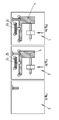
- the FIG. 1a shows an initial state at the processing station 1, on which a first work platform 4 stands.
- the tire building drum 8 is arranged with a crowning device. About a rotational movement of the tire building drum 8 tire building parts are wound up at the individual processing stations.
- a first socket 6 and a second socket 7 of the working platform 4 is arranged on the underside of the work platform 4.
- the extendable stationary connector 9 of the processing station 1 is arranged below the working platform 4.
- the stationary plug 9 is coupled as shown in the working platform 4 and supplies them continuously with energy. The energy is particularly necessary to control the rotational movement of the tire building drum 8. It is conceivable, for example, that the tire belt for the vehicle tire is placed on this processing station.
- a second socket 7 of the work platform is arranged approximately in the middle. About this parallel second socket 7, the work platform can also be supplied with energy.
- the work platform can be moved via rails, not shown, from one processing station to the next processing station.
- FIG. 1B shows a second processing station 2.
- a second work platform 5 At this processing station is a second work platform 5 at.
- a first drive carriage 13 is arranged, which is also moved via a rail system. The drive carriage 13 is disengaged from the work platform 5 and is in the next step from the second processing station 2 to the first processing station 1 in FIG. 1a method.
- the Figure 1c shows a third processing station, in which no work platform is applied.
- the second drive carriage 12 shown there moves in the next method step to the second processing station 2.
- the plug 13 is in a retracted state.
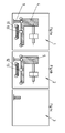
- the FIG. 2a shows the processing station 1 in a next step.
- the drive carriage 13 has now moved under the work platform 4.
- the stationary plug 9 is still coupled into the working platform 4 and supplies it with energy.
- FIGS. 2b and 2c show that the drive carriage has been moved from the processing station 3 to the processing station 2.
- the drive carriage 12 is now below the working platform. 5
- FIG. 3a shows the process step in which the plug 13 of the drive carriage 11 is engaged in the second socket of the working platform 4.
- the working platform can be supplied via the first socket as well as the second socket with appropriate energy.
- FIG. 3b shows how parallel to the processing station 2, the plug 13 of the drive carriage 12 has also been engaged in the work platform 5.
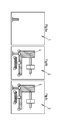
- FIGS. 4c shows the state at the processing station 3, wherein at this processing station no working platform is applied.
- FIGS. 5c shows the state at the processing station 3, wherein at this processing station no working platform is applied. The same goes for the FIGS. 4c as well as the FIGS. 5c ,
- FIG. 4a shows the process step in which the extendable stationary connector 9 is disengaged from the work platform 4.
- the power supply is now exclusively via the engaged connector 13 of the drive carriage eleventh
- FIG. 4b shows the parallel operation at the processing station 2.
- FIG. 5a shows the process of how the drive carriage 11 moves from the processing station 1 with the docked work platform 4 to the processing station 2.
- FIG. 5b shows how the drive carriage 12 is moved with the docked working platform 5 to the processing station 3 at the same time.
- the drive carriage 12 and 13 are in turn supplied via entrained lines with energy.
- the Figures 6a, 6b and 6c show the state in which the work platform 4 and 5 have moved to the processing stations 2 and 3. At the processing station 1 is now no work platform more.
- FIGS. 7a and FIG. 8a show the same goes for the FIGS. 7a and FIG. 8a ,
- FIG. 7b the process is shown in which the retractable stationary connector 9 has been engaged in the work platform 4. Beforehand, the work platform was locked in the processing station 2.
- FIG. 7c shows the parallel operation at the processing station 3, in which the extendable plug 9 is coupled into the working platform 5.
- FIG. 8b shows the state in which the plug 13 of the drive carriage 11 has been decoupled.
- the work platform 4 is now supplied exclusively via the stationary connector 9 with energy.
- the drive carriage 11 would travel back from the processing station 2 to the processing station 1.
- FIG. 8c shows the parallel operation at the processing station 3.
- the plug 13 of the drive carriage 12 has been decoupled from the work platform 5.
- the drive carriage 12 would travel from the processing station 3 back to the processing station 2.
- each work platform is passed from one processing platform to the next processing station, ensuring at all times that the work platform is powered without interruptions.
Landscapes
- Engineering & Computer Science (AREA)
- Mechanical Engineering (AREA)
- Tyre Moulding (AREA)
- Processing And Handling Of Plastics And Other Materials For Molding In General (AREA)
- Automobile Manufacture Line, Endless Track Vehicle, Trailer (AREA)
Abstract
Description
- Die Erfindung betrifft ein Verfahren zur kontinuierlichen Zuführung von Energie zu einer verfahrbaren Arbeitsplattform für die Herstellung von Fahrzeugreifen.
- Bei der Herstellung von Fahrzeugreifen besteht ein Herstellungskonzept darin, eine wandernde Reifenaufbautrommel an verschiedenen Bearbeitungsstationen vorbei zufahren. An den einzelnen Bearbeitungsstationen werden unterschiedliche Reifenaufbauteile auf die Reifenaufbautrommel aufgelegt, beispielsweise der Laufstreifen in aufgespulter Form. Die wandernde Reifenaufbautrommel ist dabei auf einer Arbeitsplattform angeordnet, die wiederum auf einer kreisförmigen Bearbeitungsstrecke geführt wird. Die Reifenaufbautrommel muss fortwährend mit Energie versorgt werden, um beispielsweise eine kontrollierte Rotation der Reifenaufbautrommel zu ermöglichen. Es ist nicht möglich die Arbeitsplattform über ständig mitgeführte Leitungen kontinuierlich mit Energie zu versorgen, da die Arbeitsplattform fortwährend im Kreis geführt wird und dadurch sich die Leitungen unkontrolliert aufwickeln würden. Dies könnte zu einem Leitungsbruch der mitgeführten Leitungen führen und damit zu einem Stillstand der Anlage.
- Der Erfindung lag die Aufgabe zugrunde, ein Verfahren bereitzustellen, mit dem auf eine einfache Weise die Arbeitsplattform kontinuierlich mit Energie versorgt wird.
- Gelöst wird die Aufgabe durch ein Verfahren gemäß Anspruch 1 mit folgenden Schritten:
- Bereitstellen einer Arbeitsplattform an einer ersten Bearbeitungsstation, wobei ein erster stationärer Stecker der ersten Bearbeitungsstation in eine erste Buchse der Arbeitsplattform eingekoppelt ist und diese mit Energie versorgt,
- Ankoppeln eines Antriebswagens an die Arbeitsplattform,
- Einkoppeln eines Steckers des Antriebswagens an eine zweite Buchse an der Arbeitsplattform, wobei über den Stecker eine Zuführung von Energie erfolgt,
- Auskoppeln des ersten stationären Steckers an der Bearbeitungsstation aus der ersten Buchse an der Arbeitsplattform
- Verfahren der Arbeitsplattform mit dem angekoppelten Antriebswagen zu einer zweiten Bearbeitungsstation
- Einkoppeln eines zweiten stationären Steckers an der zweiten Bearbeitungsstation aus der ersten Buchse an der Arbeitsplattform,
- Auskoppeln des Steckers des Antriebswagen aus der zweiten Buchse an der Arbeitsplattform,
- Zurückfahren des Antriebswagen in eine Ausgangsposition und Durchführen von Bearbeitungsschritten an der Arbeitsplattform in der zweiten Bearbeitungsstation.
- Ein Vorteil der Erfindung ist insbesondere darin zu sehen, dass durch das erfindungsgemäße Verfahren eine kontinuierliche Versorgung der Arbeitsplattform mit Energie sicher gestellt ist. Das Verfahren gewährleistet, dass die Arbeitsplattform über eine der beiden Buchsen ständig mit Energie versorgt wird. Zu keinen Zeitpunkt wird somit eine Energiezuführung zu der Arbeitsplattform unterbrochen.
- In einer vorteilhaften Weiterbildung der Erfindung ist vorgesehen, dass der Antriebswagen über mitgeführte Leitungen kontinuierlich mit Energie versorgt wird. Der Antriebswagen, der sich im Regelfall nur zwischen zwei Bearbeitungsstationen hin und her bewegt, wird über mitgeführte Leitungen, die vorzugsweise unter dem Antriebswagen angeordnet sind, mit Energie versorgt. Da sich die Antriebswagen nur zwischen zwei Bearbeitungsstationen hin- und herbewegen ist die Beanspruchung der mitgeführten Leitungen gering.
- In einer weiteren vorteilhaften Weiterbildung der Erfindung ist vorgesehen, dass auf der Bearbeitungsstrecke mindestens zwei Arbeitsplattformen von einer Bearbeitungsstation zur nächsten Bearbeitungsstation geführt werden. Auf diese Weise können an den einzelnen Bearbeitungsstationen mehrere Fahrzeugreifen gleichzeitig hergestellt werden.
- In einer weiteren vorteilhaften Weiterbildung der Erfindung ist vorgesehen, dass die einzelnen Arbeitsplattformen mit einer Vielzahl von Antriebswagen auf der Bearbeitungsstrecke verfahren werden. Die Vielzahl von Antriebswagen gewährleistet, dass die Arbeitsplattform mit hoher Geschwindigkeit von einer Bearbeitungsstation zur nächsten Bearbeitungsstation weiter gereicht werden kann.
- In einer weiteren vorteilhaften Weiterbildung der Erfindung ist vorgesehen, dass die Arbeitsplattform kontinuierlich mit Energie in Form von Druckluft und elektrischen Strom versorgt wird. Druckluft ist insbesondere für die pneumatischen Vorrichtungen notwendig, die auf der Arbeitsplattform angeordnet sind.
- In einer weiteren vorteilhaften Weiterbildung der Erfindung ist vorgesehen, dass die Arbeitsplattform kontinuierlich mit einer Datenleitung zur Steuerung der Arbeitsplattform verbunden ist. Insbesondere ist es notwendig die Rotationsgeschwindigkeit der Reifenaufbautrommel zu steuern.
- In einer weiteren vorteilhaften Weiterbildung der Erfindung ist vorgesehen, dass die Arbeitsplattform eine drehbare Reifenaufbautrommel umfasst. Auf der drehbaren Reifenaufbautrommel werden unterschiedliche Reifenaufbauteile aufgelegt.
- In einer weiteren vorteilhaften Weiterbildung der Erfindung ist vorgesehen, dass die Reifenaufbautrommel eine Bombiervorichtung für die Herstellung eines Fahrzeugreifens umfasst. Die Bombiervorrichtung sorgt dafür, dass der Fahrzeugreifen beim Auflegen von Reifenaufbauteilen eine Endkonturnahe Form besitzt.
- In einer weiteren vorteilhaften Weiterbildung der Erfindung ist vorgesehen, dass an den einzelnen Bearbeitungsstationen eine Komplettierung des Fahrzeugreifens mit unterschiedlichen Reifenaufbauteilen erfolgt. Dadurch wird gewährleistet, dass die Anlage sich durch eine insgesamt hohe Flexibilität auszeichnet.
- In einer weiteren vorteilhaften Weiterbildung der Erfindung ist vorgesehen, dass die Arbeitsplattform und der Antriebswagen auf Schienen verfahren werden. Auf diese Weise kann die Arbeitsplattform mit einer hohen Geschwindigkeit von Bearbeitungsstationen zu Bearbeitungsstationen weiter gereicht werden.
- Anhand eines Ausführungsbeispiels soll die Erfindung näher erläutert werden. Es zeigen: Die
Figuren 1a bis 8c unterschiedliche Verfahrensschritte. - Die
Figur 1a zeigt einen Anfangszustand an der Bearbeitungsstation 1, an der eine erste Arbeitsplattform 4 steht. Auf der Arbeitsplattform 4 ist die Reifenaufbautrommel 8 mit einer Bombiervorrichtung angeordnet. Über eine Rotationsbewegung der Reifenaufbautrommel 8 werden an den einzelnen Bearbeitungsstationen Reifenaufbauteile aufgewickel. Auf der Unterseite der Arbeitsplattform 4 ist eine erste Buchse 6 und eine zweite Buchse 7 der Arbeitsplattform 4 angeordnet. Der Ausfahrbare stationäre Stecker 9 der Bearbeitungsstation 1 ist unterhalb der Arbeitsplattform 4 angeordnet. Der stationäre Stecker 9 ist wie dargestellt in die Arbeitsplattform 4 eingekoppelt und versorgt diese kontinuierlich mit Energie. Die Energie ist insbesondere dazu notwendig, um die Rotationsbewegung der Reifenaufbautrommel 8 zu steuern. Denkbar ist zum Beispiel, dass an dieser Bearbeitungsstation der Reifengürtel für den Fahrzeugreifen aufgelegt wird. Unterhalb der Arbeitsplattform 4 ist in etwa mittig eine zweite Buchse 7 der Arbeitsplattform angeordnet. Über diese parallel geschaltete zweite Buchse 7 kann die Arbeitsplattform ebenfalls mit Energie versorgt werden. Die Arbeitsplattform ist über nicht dargestellte Schienen von einer Bearbeitungsstation zur nächsten Bearbeitungsstation verfahrbar. - Die
Figur 1B zeigt eine zweite Bearbeitungsstation 2. An dieser Bearbeitungsstation liegt eine zweite Arbeitsplattform 5 an. Unterhalb der Arbeitsplattform 5 ist ein erster Antriebswagen 13 angeordnet, der ebenfalls über ein Schienensystem bewegt wird. Der Antriebswagen 13 ist aus der Arbeitsplattform 5 ausgekuppelt und wird im nächsten Verfahrensschritt von der zweiten Bearbeitungsstation 2 zur ersten Bearbeitungsstation 1 inFigur 1a verfahren. - Die
Figur 1c zeigt eine dritte Bearbeitungsstation, in der keine Arbeitsplattform anliegt. Der dort dargestellte zweite Antriebswagen 12 bewegt sich im nächsten Verfahrensschritt zur zweiten Bearbeitungsstation 2. Der Stecker 13 befindet sich in einem eingefahrenen Zustand. DieFigur 2a zeigt die Bearbeitungsstation 1 bei einem nächsten Verfahrensschritt. Der Antriebswagen 13 ist nunmehr unter die Arbeitsplattform 4 gefahren. Der stationäre Stecker 9 ist immer noch in die Arbeitsplattform 4 eingekoppelt und versorgt diesen mit Energie.Figur 2b und 2c zeigen, dass der Antriebswagen von der Bearbeitungsstation 3 zu der Bearbeitungsstation 2 verfahren wurde. Der Antriebswagen 12 befindet sich nunmehr unterhalb der Arbeitsplattform 5. -
Figur 3a zeigt den Verfahrensschritt bei dem der Stecker 13 des Antriebswagens 11 in die zweite Buchse der Arbeitsplattform 4 eingekuppelt wird. In diesem Zustand kann die Arbeitsplattform sowohl über die erste Buchse als auch über die zweite Buchse mit entsprechender Energie versorgt werden. - Die
Figur 3b zeigt wie parallel in der Bearbeitungsstation 2 der Stecker 13 des Antriebswagens 12 ebenfalls in die Arbeitsplattform 5 eingekuppelt wurde. - Die
Figur 3c zeigt den Zustand an der Bearbeitungsstation 3, wobei an dieser Bearbeitungsstation keine Arbeitsplattform anliegt. Das gleiche gilt für dieFiguren 4c sowie dieFiguren 5c . - Die
Figur 4a zeigt den Verfahrensschritt bei dem der ausfahrbare stationäre Stecker 9 aus der Arbeitsplattform 4 ausgekuppelt wird. Die Energieversorgung erfolgt nunmehr ausschließlich über den eingekuppelten Stecker 13 des Antriebswagens 11. - Die
Figur 4b zeigt den parallelen Vorgang an der Bearbeitungsstation 2. - Die
Figur 5a zeigt den Vorgang, wie sich der Antriebswagen 11 von der Bearbeitungsstation 1 mit der angekoppelten Arbeitsplattform 4 zur Bearbeitungsstation 2 bewegt. - Die
Figur 5b zeigt, wie gleichzeitig der Antriebswagen 12 mit der angekoppelten Arbeitsplattform 5 zur Bearbeitungsstation 3 bewegt wird. Bei diesem Bewegungsvorgang erfolgt die Energieversorgung der Arbeitsplattform über die Stecker 13 der Antriebswagen 11 und 12. Die Antriebswagen 12 und 13 werden wiederum über mitgeführte Leitungen mit Energie versorgt. DieFiguren 6a, 6b und 6c zeigen den Zustand bei dem sich die Arbeitsplattform 4 und 5 zu den Bearbeitungsstationen 2 und 3 bewegt haben. An der Bearbeitungsstation 1 liegt nunmehr keine Arbeitsplattform mehr an. Das gleiche gilt für dieFiguren 7a undFigur 8a . - In der
Figur 7b wird der Vorgang gezeigt bei dem der ausfahrbare stationäre Stecker 9 in die Arbeitsplattform 4 eingekuppelt wurde. Vorab wurde die Arbeitsplattform in der Bearbeitungsstation 2 verriegelt. - Die
Figur 7c zeigt den parallelen Vorgang an der Bearbeitungsstation 3, bei dem der ausfahrbare Stecker 9 in die Arbeitsplattform 5 eingekoppelt wird. - Die
Figur 8b zeigt den Zustand bei dem der Stecker 13 des Antriebswagen 11 ausgekoppelt wurde. Die Arbeitsplattform 4 wird nunmehr ausschließlich über den stationären Stecker 9 mit Energie versorgt. In einem nachfolgenden Verfahrensschritt würde der Antriebswagen 11 von der Bearbeitungsstation 2 zu der Bearbeitungsstation 1 zurückfahren. -
Figur 8c zeigt den parallelen Vorgang an der Bearbeitungsstation 3. Der Stecker 13 des Antriebswagens 12 ist aus der Arbeitsplattform 5 ausgekoppelt worden. Im nächsten Verfahrensschritt würde der Antriebswagen 12 von der Bearbeitungsstation 3 zu der Bearbeitungsstation 2 zurück fahren. Auf diese Weise wird jeder Arbeitsplattform von einer Bearbeitungsplattform zur nächsten Bearbeitungsstation gereicht, wobei zu jeder Zeit gewährleistet ist, dass die Arbeitsplattform ohne Unterbrechungen mit Energie versorgt wird. -
- 1 Bearbeitungsstation 1
- 2 Bearbeitungsstation 2
- 3 Bearbeitungsstation 3
- 4 erste Arbeitsplattform
- 5 zweite Arbeitsplattform
- 6 erste Buchse der Arbeitsplattform
- 7 zweite Buchse der Arbeitsplattform
- 8 Reifenaufbautrommel mit Bombiervorrichtung
- 9 Ausfahrbarer stationärer Stecker der Bearbeitungsstation 1 10 stationärer Stecker der Bearbeitungsstation2
- 11 erster Antriebswagen
- 12 zweiter Antriebswagen
- 13 ausfahrbarer Stecker des Antriebswagen
Claims (10)
- Verfahren zur kontinuierlichen Zuführung von Energie zu einer verfahrbaren Arbeitsplattform (4, 5) für die Herstellung von Fahrzeugreifen, wobei die Arbeitsplattform (4, 5) an einer Vielzahl von Bearbeitungsstationen (1, 2, 3) vorbei auf einer im Wesentlichen kreisförmigen Bearbeitungsstrecke geführt wird, mit folgenden Schritten:- Bereitstellen einer Arbeitsplattform (4, 5) an einer ersten Bearbeitungsstation (1, 2, 3), wobei ein erster stationärer Stecker (9) der ersten Bearbeitungsstation in eine erste Buchse (6) der Arbeitsplattform (4, 5) eingekoppelt ist und diese mit Energie versorgt,- Ankoppeln eines Antriebswagens (11, 12) an die Arbeitsplattform (4, 5),- Einkoppeln eines Steckers (13) des Antriebswagens (11, 12) an eine zweite Buchse (7) an der Arbeitsplattform (4, 5), wobei über den Stecker (13) eine Zuführung von Energie erfolgt,- Auskoppeln des ersten stationären Steckers (9) an der Bearbeitungsstation (1, 2, 3) aus der ersten Buchse (6) an der Arbeitsplattform (4, 5)- Verfahren der Arbeitsplattform (4, 5) mit dem angekoppelten Antriebswagen (11, 12) zu einer zweiten Bearbeitungsstation (2, 3)- Einkoppeln eines zweiten stationären Steckers (9) an der zweiten Bearbeitungsstation (2, 3) aus der ersten Buchse (6) an der Arbeitsplattform (4, 5),- Auskoppeln des Steckers (13) des Antriebswagen (11, 12) aus der zweiten Buchse (7) an der Arbeitsplattform (4, 5),- Zurückfahren des Antriebswagen (11, 12) in eine Ausgangsposition und Durchführen von Bearbeitungsschritten an der Arbeitsplattform in der zweiten Bearbeitungsstation (1, 2, 3).
- Verfahren nach Anspruch 1,
dadurch gekennzeichnet, dass
der Antriebswagen (11, 12) über mitgeführte Leitungen kontinuierlich mit Energie versorgt wird. - Verfahren nach Anspruch 1 oder 2,
dadurch gekennzeichnet, dass
das auf der Bearbeitungsstrecke mindestens zwei Arbeitsplattformen (4, 5) von einer Bearbeitungsstation (1, 2, 3) zur nächsten Bearbeitungsstation (1, 2, 3) geführt werden. - Verfahren nach einem der Ansprüche 1 bis 3,
dadurch gekennzeichnet, dass
die einzelnen Arbeitsplattformen (4, 5) mit einer Vielzahl von Antriebswagen (11, 12) auf der Bearbeitungsstrecke verfahren werden. - Verfahren nach einem der Ansprüche 1 bis 4,
dadurch gekennzeichnet, dass
die Arbeitsplattform (4, 5) kontinuierlich mit Energie in Form von Druckluft und elektrischen Strom versorgt wird. - Verfahren nach einem der Ansprüche 1 bis 5,
dadurch gekennzeichnet, dass
die Arbeitsplattform (4, 5) kontinuierlich mit einer Datenleitung zur Steuerung der Arbeitsplattform (4, 5) verbunden ist. - Verfahren nach einem der Ansprüche 1 bis 6,
dadurch gekennzeichnet, dass
die Arbeitsplattform (4, 5) eine drehbare Reifenaufbautrommel (8) umfasst. - Verfahren nach einem der Ansprüche 1 bis 7,
dadurch gekennzeichnet, dass
die Reifenaufbautrommel (8) eine Bombiervorichtung für die Herstellung eines Fahrzeugreifens umfasst. - Verfahren nach einem der Ansprüche 1 bis 8,
dadurch gekennzeichnet, dass
an den einzelnen Bearbeitungsstationen (1, 2, 3) eine Komplettierung des Fahrzeugreifens mit unterschiedlichen Reifenaufbauteilen erfolgt. - Verfahren nach einem der Ansprüche 1 bis 9,
dadurch gekennzeichnet, dass
die Arbeitsplattform (4, 5) und der Antriebswagen (11, 12) auf Schienen verfahren werden.
Applications Claiming Priority (1)
| Application Number | Priority Date | Filing Date | Title |
|---|---|---|---|
| DE102007041681A DE102007041681A1 (de) | 2007-09-01 | 2007-09-01 | Verfahren zur kontinuierlichen Zuführung von Energie zu einer verfahrbaren Arbeitsplattform für die Herstellung von Fahrzeugreifen |
Publications (2)
| Publication Number | Publication Date |
|---|---|
| EP2030771A1 true EP2030771A1 (de) | 2009-03-04 |
| EP2030771B1 EP2030771B1 (de) | 2010-09-22 |
Family
ID=39929873
Family Applications (1)
| Application Number | Title | Priority Date | Filing Date |
|---|---|---|---|
| EP08160203A Not-in-force EP2030771B1 (de) | 2007-09-01 | 2008-07-11 | Verfahren zur kontinuierlichen Zuführung von Energie zu einer verfahrbaren Arbeitsplattform für die Herstellung von Fahrzeugreifen |
Country Status (3)
| Country | Link |
|---|---|
| EP (1) | EP2030771B1 (de) |
| AT (1) | ATE482078T1 (de) |
| DE (2) | DE102007041681A1 (de) |
Citations (5)
| Publication number | Priority date | Publication date | Assignee | Title |
|---|---|---|---|---|
| GB513127A (en) * | 1937-05-13 | 1939-10-04 | Wingfoot Corp | Improvements in method of and apparatus for building tires |
| EP0246496A2 (de) * | 1986-05-20 | 1987-11-25 | Bridgestone/Firestone, Inc. | Reifenvulkanisieranlage |
| US4805872A (en) * | 1983-01-17 | 1989-02-21 | The Firestone Tire & Rubber Company | Shaping turret |
| EP1566159A2 (de) * | 2004-02-19 | 2005-08-24 | Datex-Ohmeda, Inc. | Brennstoffzellenbetriebener Transportwagen für Patienten |
| DE102005055609A1 (de) * | 2005-11-22 | 2007-05-24 | Continental Aktiengesellschaft | Transport- und Fertigungssystem zur Verwendung beim Aufbau von Reifenrohlingen |
-
2007
- 2007-09-01 DE DE102007041681A patent/DE102007041681A1/de not_active Withdrawn
-
2008
- 2008-07-11 EP EP08160203A patent/EP2030771B1/de not_active Not-in-force
- 2008-07-11 DE DE502008001372T patent/DE502008001372D1/de active Active
- 2008-07-11 AT AT08160203T patent/ATE482078T1/de active
Patent Citations (5)
| Publication number | Priority date | Publication date | Assignee | Title |
|---|---|---|---|---|
| GB513127A (en) * | 1937-05-13 | 1939-10-04 | Wingfoot Corp | Improvements in method of and apparatus for building tires |
| US4805872A (en) * | 1983-01-17 | 1989-02-21 | The Firestone Tire & Rubber Company | Shaping turret |
| EP0246496A2 (de) * | 1986-05-20 | 1987-11-25 | Bridgestone/Firestone, Inc. | Reifenvulkanisieranlage |
| EP1566159A2 (de) * | 2004-02-19 | 2005-08-24 | Datex-Ohmeda, Inc. | Brennstoffzellenbetriebener Transportwagen für Patienten |
| DE102005055609A1 (de) * | 2005-11-22 | 2007-05-24 | Continental Aktiengesellschaft | Transport- und Fertigungssystem zur Verwendung beim Aufbau von Reifenrohlingen |
Also Published As
| Publication number | Publication date |
|---|---|
| DE102007041681A1 (de) | 2009-09-10 |
| ATE482078T1 (de) | 2010-10-15 |
| DE502008001372D1 (de) | 2010-11-04 |
| EP2030771B1 (de) | 2010-09-22 |
Similar Documents
| Publication | Publication Date | Title |
|---|---|---|
| EP2616197B1 (de) | Vorrichtung und verfahren zur herstellung von zumindest teilweise geschlossenen hohlprofilen mit drehbaren gesenkhälften und geringer taktzeit | |
| DE102014103599B4 (de) | Maschine und Verfahren zur Herstellung von Bürsten | |
| EP2358519B1 (de) | Vorrichtung zum aufbau einer reifenkarkasse für einen fahrzeugreifen | |
| DE102012108717A1 (de) | Verfahren zum Modifizieren der Flanken eines Zahns eines Zahnrads mit Hilfe eines Werkzeugs | |
| EP2746021A1 (de) | Verfahren und Vorrichtung zum Herstellen von Formteilen | |
| EP2866994A1 (de) | Handhabungsvorrichtung zum handhaben einer rotorblattform zum fertigen eines rotorblattes einer windenergieanlage | |
| WO2015062729A1 (de) | Fördervorrichtung zur förderung von werkstücken, insbesondere leiterplatten, in förderrichtung entlang einer förderstrecke | |
| EP3066533A1 (de) | Verfahren zur bearbeitung eines rohteils mittels eines werkzeuges | |
| EP1957261B1 (de) | Transport- und fertigungssystem zur verwendung beim aufbau von reifenrohlingen | |
| DE102018106980A1 (de) | Vorrichtung und Verfahren zum Biegen von Draht für die Herstellung von Maschinenelementen elektrischer Maschinen | |
| DE19918523C1 (de) | Reifenaufbauvorrichtung | |
| EP2030771B1 (de) | Verfahren zur kontinuierlichen Zuführung von Energie zu einer verfahrbaren Arbeitsplattform für die Herstellung von Fahrzeugreifen | |
| EP3581325A1 (de) | Verfahren und vorrichtung zur bearbeitung der radlaufflächen von rädern für schienenfahrzeuge | |
| EP4269065A2 (de) | Sortiereinrichtung und zuführschiene für kunststoffvorformlinge | |
| DE60318984T2 (de) | System und Verfahren zum Herstellen eines Laufflächenrings aus elastomerem Material | |
| BE1021677B1 (de) | Bürstenherstellungsmachine | |
| EP2903807B1 (de) | Hochschlagvorrichtung für reifenseitenwände | |
| DE2624585B2 (de) | Vulkanisierbarer rohlaufstreifen zum aufbringen auf eine luftreifenkarkasse und vorrichtung zur herstellung desselben | |
| WO2020088930A1 (de) | Verfahren zur herstellung von bürsten und bürstenherstellungsmaschine | |
| DE102022100201A1 (de) | Allgemeine Plattform zum Verarbeiten von Werkstücken | |
| EP3410546A1 (de) | Verfahren zur herstellung eines kontaktelements für einen steckverbinder | |
| EP3670427B1 (de) | Unterflurhebevorrichtung | |
| AT522560B1 (de) | Anordnung zur Herstellung wenigstens eines dreidimensionalen Bauteils für die Bauindustrie | |
| DE202010005011U1 (de) | Rundtisch- oder Ovalanlage | |
| DE202020101754U1 (de) | Wechselvorrichtung für einen Wechsel von wenigstens zwei Werkstückauflagen für eine Bearbeitungsmaschine |
Legal Events
| Date | Code | Title | Description |
|---|---|---|---|
| PUAI | Public reference made under article 153(3) epc to a published international application that has entered the european phase |
Free format text: ORIGINAL CODE: 0009012 |
|
| AK | Designated contracting states |
Kind code of ref document: A1 Designated state(s): AT BE BG CH CY CZ DE DK EE ES FI FR GB GR HR HU IE IS IT LI LT LU LV MC MT NL NO PL PT RO SE SI SK TR |
|
| AX | Request for extension of the european patent |
Extension state: AL BA MK RS |
|
| 17P | Request for examination filed |
Effective date: 20090904 |
|
| AKX | Designation fees paid |
Designated state(s): AT BE BG CH CY CZ DE DK EE ES FI FR GB GR HR HU IE IS IT LI LT LU LV MC MT NL NO PL PT RO SE SI SK TR |
|
| RAP1 | Party data changed (applicant data changed or rights of an application transferred) |
Owner name: CONTINENTAL REIFEN DEUTSCHLAND GMBH |
|
| GRAP | Despatch of communication of intention to grant a patent |
Free format text: ORIGINAL CODE: EPIDOSNIGR1 |
|
| RTI1 | Title (correction) |
Free format text: METHOD FOR CONTINUOUSLY SUPPLYING ENERGY TO A MOVABLE WORK PLATFORM FOR PRODUCING VEHICLE TYRES |
|
| GRAS | Grant fee paid |
Free format text: ORIGINAL CODE: EPIDOSNIGR3 |
|
| GRAA | (expected) grant |
Free format text: ORIGINAL CODE: 0009210 |
|
| AK | Designated contracting states |
Kind code of ref document: B1 Designated state(s): AT BE BG CH CY CZ DE DK EE ES FI FR GB GR HR HU IE IS IT LI LT LU LV MC MT NL NO PL PT RO SE SI SK TR |
|
| REG | Reference to a national code |
Ref country code: GB Ref legal event code: FG4D Free format text: NOT ENGLISH |
|
| REG | Reference to a national code |
Ref country code: CH Ref legal event code: EP |
|
| REG | Reference to a national code |
Ref country code: IE Ref legal event code: FG4D Free format text: LANGUAGE OF EP DOCUMENT: GERMAN |
|
| REF | Corresponds to: |
Ref document number: 502008001372 Country of ref document: DE Date of ref document: 20101104 Kind code of ref document: P |
|
| REG | Reference to a national code |
Ref country code: NL Ref legal event code: T3 |
|
| PG25 | Lapsed in a contracting state [announced via postgrant information from national office to epo] |
Ref country code: LT Free format text: LAPSE BECAUSE OF FAILURE TO SUBMIT A TRANSLATION OF THE DESCRIPTION OR TO PAY THE FEE WITHIN THE PRESCRIBED TIME-LIMIT Effective date: 20100922 Ref country code: NO Free format text: LAPSE BECAUSE OF FAILURE TO SUBMIT A TRANSLATION OF THE DESCRIPTION OR TO PAY THE FEE WITHIN THE PRESCRIBED TIME-LIMIT Effective date: 20101222 Ref country code: FI Free format text: LAPSE BECAUSE OF FAILURE TO SUBMIT A TRANSLATION OF THE DESCRIPTION OR TO PAY THE FEE WITHIN THE PRESCRIBED TIME-LIMIT Effective date: 20100922 |
|
| LTIE | Lt: invalidation of european patent or patent extension |
Effective date: 20100922 |
|
| PG25 | Lapsed in a contracting state [announced via postgrant information from national office to epo] |
Ref country code: SI Free format text: LAPSE BECAUSE OF FAILURE TO SUBMIT A TRANSLATION OF THE DESCRIPTION OR TO PAY THE FEE WITHIN THE PRESCRIBED TIME-LIMIT Effective date: 20100922 Ref country code: PL Free format text: LAPSE BECAUSE OF FAILURE TO SUBMIT A TRANSLATION OF THE DESCRIPTION OR TO PAY THE FEE WITHIN THE PRESCRIBED TIME-LIMIT Effective date: 20100922 Ref country code: HR Free format text: LAPSE BECAUSE OF FAILURE TO SUBMIT A TRANSLATION OF THE DESCRIPTION OR TO PAY THE FEE WITHIN THE PRESCRIBED TIME-LIMIT Effective date: 20100922 |
|
| REG | Reference to a national code |
Ref country code: SK Ref legal event code: T3 Ref document number: E 8282 Country of ref document: SK |
|
| PG25 | Lapsed in a contracting state [announced via postgrant information from national office to epo] |
Ref country code: LV Free format text: LAPSE BECAUSE OF FAILURE TO SUBMIT A TRANSLATION OF THE DESCRIPTION OR TO PAY THE FEE WITHIN THE PRESCRIBED TIME-LIMIT Effective date: 20100922 Ref country code: GR Free format text: LAPSE BECAUSE OF FAILURE TO SUBMIT A TRANSLATION OF THE DESCRIPTION OR TO PAY THE FEE WITHIN THE PRESCRIBED TIME-LIMIT Effective date: 20101223 Ref country code: SE Free format text: LAPSE BECAUSE OF FAILURE TO SUBMIT A TRANSLATION OF THE DESCRIPTION OR TO PAY THE FEE WITHIN THE PRESCRIBED TIME-LIMIT Effective date: 20100922 |
|
| REG | Reference to a national code |
Ref country code: IE Ref legal event code: FD4D |
|
| PG25 | Lapsed in a contracting state [announced via postgrant information from national office to epo] |
Ref country code: IE Free format text: LAPSE BECAUSE OF FAILURE TO SUBMIT A TRANSLATION OF THE DESCRIPTION OR TO PAY THE FEE WITHIN THE PRESCRIBED TIME-LIMIT Effective date: 20100922 |
|
| PG25 | Lapsed in a contracting state [announced via postgrant information from national office to epo] |
Ref country code: EE Free format text: LAPSE BECAUSE OF FAILURE TO SUBMIT A TRANSLATION OF THE DESCRIPTION OR TO PAY THE FEE WITHIN THE PRESCRIBED TIME-LIMIT Effective date: 20100922 Ref country code: RO Free format text: LAPSE BECAUSE OF FAILURE TO SUBMIT A TRANSLATION OF THE DESCRIPTION OR TO PAY THE FEE WITHIN THE PRESCRIBED TIME-LIMIT Effective date: 20100922 Ref country code: IS Free format text: LAPSE BECAUSE OF FAILURE TO SUBMIT A TRANSLATION OF THE DESCRIPTION OR TO PAY THE FEE WITHIN THE PRESCRIBED TIME-LIMIT Effective date: 20110122 Ref country code: PT Free format text: LAPSE BECAUSE OF FAILURE TO SUBMIT A TRANSLATION OF THE DESCRIPTION OR TO PAY THE FEE WITHIN THE PRESCRIBED TIME-LIMIT Effective date: 20110124 |
|
| PG25 | Lapsed in a contracting state [announced via postgrant information from national office to epo] |
Ref country code: ES Free format text: LAPSE BECAUSE OF FAILURE TO SUBMIT A TRANSLATION OF THE DESCRIPTION OR TO PAY THE FEE WITHIN THE PRESCRIBED TIME-LIMIT Effective date: 20110102 |
|
| PLBE | No opposition filed within time limit |
Free format text: ORIGINAL CODE: 0009261 |
|
| STAA | Information on the status of an ep patent application or granted ep patent |
Free format text: STATUS: NO OPPOSITION FILED WITHIN TIME LIMIT |
|
| 26N | No opposition filed |
Effective date: 20110623 |
|
| PG25 | Lapsed in a contracting state [announced via postgrant information from national office to epo] |
Ref country code: DK Free format text: LAPSE BECAUSE OF FAILURE TO SUBMIT A TRANSLATION OF THE DESCRIPTION OR TO PAY THE FEE WITHIN THE PRESCRIBED TIME-LIMIT Effective date: 20100922 |
|
| REG | Reference to a national code |
Ref country code: DE Ref legal event code: R097 Ref document number: 502008001372 Country of ref document: DE Effective date: 20110623 |
|
| PG25 | Lapsed in a contracting state [announced via postgrant information from national office to epo] |
Ref country code: MT Free format text: LAPSE BECAUSE OF FAILURE TO SUBMIT A TRANSLATION OF THE DESCRIPTION OR TO PAY THE FEE WITHIN THE PRESCRIBED TIME-LIMIT Effective date: 20100922 |
|
| BERE | Be: lapsed |
Owner name: CONTINENTAL REIFEN DEUTSCHLAND G.M.B.H. Effective date: 20110731 |
|
| PG25 | Lapsed in a contracting state [announced via postgrant information from national office to epo] |
Ref country code: MC Free format text: LAPSE BECAUSE OF NON-PAYMENT OF DUE FEES Effective date: 20110731 |
|
| REG | Reference to a national code |
Ref country code: FR Ref legal event code: ST Effective date: 20120330 |
|
| PG25 | Lapsed in a contracting state [announced via postgrant information from national office to epo] |
Ref country code: BE Free format text: LAPSE BECAUSE OF NON-PAYMENT OF DUE FEES Effective date: 20110731 Ref country code: FR Free format text: LAPSE BECAUSE OF NON-PAYMENT OF DUE FEES Effective date: 20110801 |
|
| REG | Reference to a national code |
Ref country code: CH Ref legal event code: PL |
|
| GBPC | Gb: european patent ceased through non-payment of renewal fee |
Effective date: 20120711 |
|
| PG25 | Lapsed in a contracting state [announced via postgrant information from national office to epo] |
Ref country code: CH Free format text: LAPSE BECAUSE OF NON-PAYMENT OF DUE FEES Effective date: 20120731 Ref country code: GB Free format text: LAPSE BECAUSE OF NON-PAYMENT OF DUE FEES Effective date: 20120711 Ref country code: LI Free format text: LAPSE BECAUSE OF NON-PAYMENT OF DUE FEES Effective date: 20120731 |
|
| PG25 | Lapsed in a contracting state [announced via postgrant information from national office to epo] |
Ref country code: CY Free format text: LAPSE BECAUSE OF EXPIRATION OF PROTECTION Effective date: 20100922 Ref country code: LU Free format text: LAPSE BECAUSE OF NON-PAYMENT OF DUE FEES Effective date: 20110711 |
|
| PG25 | Lapsed in a contracting state [announced via postgrant information from national office to epo] |
Ref country code: TR Free format text: LAPSE BECAUSE OF FAILURE TO SUBMIT A TRANSLATION OF THE DESCRIPTION OR TO PAY THE FEE WITHIN THE PRESCRIBED TIME-LIMIT Effective date: 20100922 Ref country code: BG Free format text: LAPSE BECAUSE OF FAILURE TO SUBMIT A TRANSLATION OF THE DESCRIPTION OR TO PAY THE FEE WITHIN THE PRESCRIBED TIME-LIMIT Effective date: 20101222 |
|
| PG25 | Lapsed in a contracting state [announced via postgrant information from national office to epo] |
Ref country code: HU Free format text: LAPSE BECAUSE OF FAILURE TO SUBMIT A TRANSLATION OF THE DESCRIPTION OR TO PAY THE FEE WITHIN THE PRESCRIBED TIME-LIMIT Effective date: 20100922 |
|
| PGFP | Annual fee paid to national office [announced via postgrant information from national office to epo] |
Ref country code: DE Payment date: 20130731 Year of fee payment: 6 |
|
| REG | Reference to a national code |
Ref country code: AT Ref legal event code: MM01 Ref document number: 482078 Country of ref document: AT Kind code of ref document: T Effective date: 20130711 |
|
| PGFP | Annual fee paid to national office [announced via postgrant information from national office to epo] |
Ref country code: NL Payment date: 20140721 Year of fee payment: 7 Ref country code: CZ Payment date: 20140707 Year of fee payment: 7 |
|
| PG25 | Lapsed in a contracting state [announced via postgrant information from national office to epo] |
Ref country code: AT Free format text: LAPSE BECAUSE OF NON-PAYMENT OF DUE FEES Effective date: 20130711 |
|
| PGFP | Annual fee paid to national office [announced via postgrant information from national office to epo] |
Ref country code: SK Payment date: 20140710 Year of fee payment: 7 |
|
| PGFP | Annual fee paid to national office [announced via postgrant information from national office to epo] |
Ref country code: IT Payment date: 20140725 Year of fee payment: 7 |
|
| REG | Reference to a national code |
Ref country code: DE Ref legal event code: R119 Ref document number: 502008001372 Country of ref document: DE |
|
| REG | Reference to a national code |
Ref country code: DE Ref legal event code: R119 Ref document number: 502008001372 Country of ref document: DE Effective date: 20150203 |
|
| PG25 | Lapsed in a contracting state [announced via postgrant information from national office to epo] |
Ref country code: DE Free format text: LAPSE BECAUSE OF NON-PAYMENT OF DUE FEES Effective date: 20150203 |
|
| REG | Reference to a national code |
Ref country code: SK Ref legal event code: MM4A Ref document number: E 8282 Country of ref document: SK Effective date: 20150711 |
|
| REG | Reference to a national code |
Ref country code: NL Ref legal event code: MM Effective date: 20150801 |
|
| PG25 | Lapsed in a contracting state [announced via postgrant information from national office to epo] |
Ref country code: SK Free format text: LAPSE BECAUSE OF NON-PAYMENT OF DUE FEES Effective date: 20150711 Ref country code: CZ Free format text: LAPSE BECAUSE OF NON-PAYMENT OF DUE FEES Effective date: 20150711 Ref country code: IT Free format text: LAPSE BECAUSE OF NON-PAYMENT OF DUE FEES Effective date: 20150711 |
|
| PG25 | Lapsed in a contracting state [announced via postgrant information from national office to epo] |
Ref country code: NL Free format text: LAPSE BECAUSE OF NON-PAYMENT OF DUE FEES Effective date: 20150801 |