EP2030341B1 - Vorrichtung zum verarbeiten eines empfangssignals, verfahren dafür und verfahren zur auswahl einer abbildungsregel - Google Patents
Vorrichtung zum verarbeiten eines empfangssignals, verfahren dafür und verfahren zur auswahl einer abbildungsregel Download PDFInfo
- Publication number
- EP2030341B1 EP2030341B1 EP07746665.4A EP07746665A EP2030341B1 EP 2030341 B1 EP2030341 B1 EP 2030341B1 EP 07746665 A EP07746665 A EP 07746665A EP 2030341 B1 EP2030341 B1 EP 2030341B1
- Authority
- EP
- European Patent Office
- Prior art keywords
- mapping rule
- mapping
- demapping
- bit
- signal
- Prior art date
- Legal status (The legal status is an assumption and is not a legal conclusion. Google has not performed a legal analysis and makes no representation as to the accuracy of the status listed.)
- Not-in-force
Links
- 238000013507 mapping Methods 0.000 title claims description 180
- 238000000034 method Methods 0.000 title claims description 49
- 238000012545 processing Methods 0.000 title claims description 7
- 230000011664 signaling Effects 0.000 claims description 14
- 230000000694 effects Effects 0.000 description 26
- 230000005540 biological transmission Effects 0.000 description 24
- 230000000875 corresponding effect Effects 0.000 description 24
- 230000006854 communication Effects 0.000 description 17
- 238000004891 communication Methods 0.000 description 16
- 238000002372 labelling Methods 0.000 description 14
- 230000001965 increasing effect Effects 0.000 description 13
- 238000010586 diagram Methods 0.000 description 10
- 230000008569 process Effects 0.000 description 8
- 238000001514 detection method Methods 0.000 description 6
- 238000005562 fading Methods 0.000 description 5
- 238000007476 Maximum Likelihood Methods 0.000 description 4
- 238000004364 calculation method Methods 0.000 description 4
- 230000002708 enhancing effect Effects 0.000 description 3
- 230000001603 reducing effect Effects 0.000 description 3
- 230000002596 correlated effect Effects 0.000 description 2
- 238000012804 iterative process Methods 0.000 description 2
- 239000011159 matrix material Substances 0.000 description 2
- 238000010295 mobile communication Methods 0.000 description 2
- 238000012986 modification Methods 0.000 description 2
- 230000004048 modification Effects 0.000 description 2
- 238000005457 optimization Methods 0.000 description 2
- 230000002459 sustained effect Effects 0.000 description 2
- 230000002123 temporal effect Effects 0.000 description 2
- 101100228469 Caenorhabditis elegans exp-1 gene Proteins 0.000 description 1
- 230000009471 action Effects 0.000 description 1
- 238000004422 calculation algorithm Methods 0.000 description 1
- 230000008859 change Effects 0.000 description 1
- 238000011161 development Methods 0.000 description 1
- 230000018109 developmental process Effects 0.000 description 1
- 230000006872 improvement Effects 0.000 description 1
- 230000002441 reversible effect Effects 0.000 description 1
- 230000008054 signal transmission Effects 0.000 description 1
- 238000004088 simulation Methods 0.000 description 1
- 238000001228 spectrum Methods 0.000 description 1
- 238000012360 testing method Methods 0.000 description 1
Images


Classifications
-
- H—ELECTRICITY
- H04—ELECTRIC COMMUNICATION TECHNIQUE
- H04L—TRANSMISSION OF DIGITAL INFORMATION, e.g. TELEGRAPHIC COMMUNICATION
- H04L1/00—Arrangements for detecting or preventing errors in the information received
- H04L1/02—Arrangements for detecting or preventing errors in the information received by diversity reception
-
- H—ELECTRICITY
- H04—ELECTRIC COMMUNICATION TECHNIQUE
- H04B—TRANSMISSION
- H04B7/00—Radio transmission systems, i.e. using radiation field
- H04B7/02—Diversity systems; Multi-antenna system, i.e. transmission or reception using multiple antennas
- H04B7/04—Diversity systems; Multi-antenna system, i.e. transmission or reception using multiple antennas using two or more spaced independent antennas
- H04B7/08—Diversity systems; Multi-antenna system, i.e. transmission or reception using multiple antennas using two or more spaced independent antennas at the receiving station
- H04B7/0891—Space-time diversity
-
- H—ELECTRICITY
- H04—ELECTRIC COMMUNICATION TECHNIQUE
- H04B—TRANSMISSION
- H04B7/00—Radio transmission systems, i.e. using radiation field
- H04B7/02—Diversity systems; Multi-antenna system, i.e. transmission or reception using multiple antennas
- H04B7/04—Diversity systems; Multi-antenna system, i.e. transmission or reception using multiple antennas using two or more spaced independent antennas
- H04B7/06—Diversity systems; Multi-antenna system, i.e. transmission or reception using multiple antennas using two or more spaced independent antennas at the transmitting station
- H04B7/0613—Diversity systems; Multi-antenna system, i.e. transmission or reception using multiple antennas using two or more spaced independent antennas at the transmitting station using simultaneous transmission
- H04B7/0667—Diversity systems; Multi-antenna system, i.e. transmission or reception using multiple antennas using two or more spaced independent antennas at the transmitting station using simultaneous transmission of delayed versions of same signal
- H04B7/0669—Diversity systems; Multi-antenna system, i.e. transmission or reception using multiple antennas using two or more spaced independent antennas at the transmitting station using simultaneous transmission of delayed versions of same signal using different channel coding between antennas
-
- H—ELECTRICITY
- H04—ELECTRIC COMMUNICATION TECHNIQUE
- H04B—TRANSMISSION
- H04B7/00—Radio transmission systems, i.e. using radiation field
- H04B7/02—Diversity systems; Multi-antenna system, i.e. transmission or reception using multiple antennas
- H04B7/04—Diversity systems; Multi-antenna system, i.e. transmission or reception using multiple antennas using two or more spaced independent antennas
- H04B7/08—Diversity systems; Multi-antenna system, i.e. transmission or reception using multiple antennas using two or more spaced independent antennas at the receiving station
-
- H—ELECTRICITY
- H04—ELECTRIC COMMUNICATION TECHNIQUE
- H04L—TRANSMISSION OF DIGITAL INFORMATION, e.g. TELEGRAPHIC COMMUNICATION
- H04L1/00—Arrangements for detecting or preventing errors in the information received
- H04L1/0001—Systems modifying transmission characteristics according to link quality, e.g. power backoff
- H04L1/0002—Systems modifying transmission characteristics according to link quality, e.g. power backoff by adapting the transmission rate
- H04L1/0003—Systems modifying transmission characteristics according to link quality, e.g. power backoff by adapting the transmission rate by switching between different modulation schemes
-
- H—ELECTRICITY
- H04—ELECTRIC COMMUNICATION TECHNIQUE
- H04L—TRANSMISSION OF DIGITAL INFORMATION, e.g. TELEGRAPHIC COMMUNICATION
- H04L1/00—Arrangements for detecting or preventing errors in the information received
- H04L1/004—Arrangements for detecting or preventing errors in the information received by using forward error control
- H04L1/0045—Arrangements at the receiver end
- H04L1/0047—Decoding adapted to other signal detection operation
- H04L1/005—Iterative decoding, including iteration between signal detection and decoding operation
-
- H—ELECTRICITY
- H04—ELECTRIC COMMUNICATION TECHNIQUE
- H04L—TRANSMISSION OF DIGITAL INFORMATION, e.g. TELEGRAPHIC COMMUNICATION
- H04L1/00—Arrangements for detecting or preventing errors in the information received
- H04L1/02—Arrangements for detecting or preventing errors in the information received by diversity reception
- H04L1/06—Arrangements for detecting or preventing errors in the information received by diversity reception using space diversity
- H04L1/0618—Space-time coding
- H04L1/0631—Receiver arrangements
-
- H—ELECTRICITY
- H04—ELECTRIC COMMUNICATION TECHNIQUE
- H04L—TRANSMISSION OF DIGITAL INFORMATION, e.g. TELEGRAPHIC COMMUNICATION
- H04L25/00—Baseband systems
- H04L25/02—Details ; arrangements for supplying electrical power along data transmission lines
- H04L25/06—Dc level restoring means; Bias distortion correction ; Decision circuits providing symbol by symbol detection
- H04L25/067—Dc level restoring means; Bias distortion correction ; Decision circuits providing symbol by symbol detection providing soft decisions, i.e. decisions together with an estimate of reliability
-
- H—ELECTRICITY
- H04—ELECTRIC COMMUNICATION TECHNIQUE
- H04L—TRANSMISSION OF DIGITAL INFORMATION, e.g. TELEGRAPHIC COMMUNICATION
- H04L1/00—Arrangements for detecting or preventing errors in the information received
- H04L1/004—Arrangements for detecting or preventing errors in the information received by using forward error control
- H04L1/0041—Arrangements at the transmitter end
-
- H—ELECTRICITY
- H04—ELECTRIC COMMUNICATION TECHNIQUE
- H04L—TRANSMISSION OF DIGITAL INFORMATION, e.g. TELEGRAPHIC COMMUNICATION
- H04L27/00—Modulated-carrier systems
- H04L27/26—Systems using multi-frequency codes
- H04L27/2601—Multicarrier modulation systems
- H04L27/2647—Arrangements specific to the receiver only
Definitions
- the present invention relates to a mobile communication system, and more particularly, to an apparatus for processing a received signal, method thereof, and method for selecting-mapping rule.
- multi-antennas are used to provide transmission diversity.
- An information capacity in the radio communication system can be considerably increased if the multiple transceiving antennas are used. If the multiple transceiving antennas are used together with a coding scheme, it is able to increase a transceived information capacity more effectively.
- the coding scheme is called a spatiotemporal coding scheme.
- spatiotemporal coding scheme in order for a receiving terminal to provide a full diversity effect and a coding gain without sacrificing a bandwidth, temporal and spatial correlations with signals transmitted from other antennas are configured with codes.
- STBC space time block code
- FIG. 1A and FIG. 1B are exemplary block diagrams of a transmitting terminal structure and a receiving terminal structure, respectively.
- a bit interleaved coded orthogonal frequency division multiplexing system using STBC includes a transmitting terminal 10 and a receiving terminal 100.
- the transmitting terminal 10 includes a channel encoder 11, a bit interleaver 12, a serial/parallel converter 13, a mapping module 14 having at least two mappers 14a, an STBC encoder 15, and an inverse discrete Fourier transform (IDFT) module 16 having at least two inverse discrete Fourier transformers 16a.
- IDFT inverse discrete Fourier transform
- the channel encoder 11 attaches redundant bits to data bits to detect or correct an error that may be generated when transmitting via a channel.
- the bit interleaver 12 mixes and disperses the coded bits by a prescribed bit unit so as to independently arrange the coded bits.
- the serial/parallel converter 13 converts a bit signal from serial sequence to parallel sequence.
- Each of the mappers 14a included in the mapping module 14 transforms a bit signal inputted thereto into a corresponding symbol signal in correspondence to a prescribed mapping rule.
- the STBC encoder 15 encodes the symbol signal using a block code for multi-antennas to obtain transmission diversity in time and space.
- Each of the IDFTs 16a included in the IDFT module 16 modulates the symbol signal into an OFDM symbol, that is, transforms the symbol signal on a frequency domain into a signal on a time domain, and then transmits the transformed signal. If the IDFT 16a is replaced by an inverse fast Fourier transformer (IFFT), a quantity of calculation is reduced for more efficient implementation.
- IFFT inverse fast Fourier transformer
- the receiving terminal 20 includes a discrete Fourier transform (DFT) module 106 having at least two discrete Fourier transformers 106a, an STBC decoder 105, a demapping module 104 having at least two demappers 104a, a parallel/serial converter 103, a bit deinterleaver 102, and a channel decoder 101.
- DFT discrete Fourier transform
- Each of the discrete Fourier transformers 106a included in the discrete Fourier transform module 106 performs Fourier transform on the received OFDM symbol. If the symbol is modulated by the inverse fast Fourier transformer, the discrete Fourier transformer 106a can be replaced by a fast Fourier transformer.
- the STBC decoder 105 and the demapper 104a transform the symbol signal transmitted via the multi-antennas into a bit signal.
- the parallel/serial converter 103 converts the bit signal from parallel sequence to serial sequence in a manner reverse to that of the serial/parallel converter 13.
- the bit deinterleaver 102 changes an order of the bit signal of serial sequence mixed by the interleaver 12 into the original order prior to the mixing.
- the channel decoder 101 decides estimated data bits.
- U.S. patent application publication No. US 2006/036922 describes an apparatus and method for changing a signal mapping rule for a retransmission in a MIMO HARQ system using a space-time block code (STBC).
- STBC space-time block code
- U.S. patent application publication No. US 2003/235149 describes a system that employs space-time coding characterized at the transmitter by coded modulation, such as bit-interleaved coded modulation (BICM), combined with OFDM over multiple transmit and/or receive antennas.
- coded modulation such as bit-interleaved coded modulation (BICM)
- the gray mapping rule shows good performance in execution without iteration, the performance is degraded in the error floor region where iterative decoding is executed.
- decoding execution is associated with a limited code length.
- mutual action is not effective between bits distant from each other in a lattice structure. So, in case of using an input data sequence having a considerably long length, effects can be degraded. Even if improvement is obtained by increasing the limited code length, it is disadvantageous that configurational complexity in a decoder may increase exponentially.
- the present invention is directed to an apparatus for processing a received signal, method thereof, and mapping rule selecting method that substantially obviate one or more of the problems due to limitations and disadvantages of the related art.
- An object of the present invention is to provide an apparatus for processing a received signal, method thereof, and method for selecting mapping rule, by which radio communications can be smoothly carried out in a receiving terminal receiving signals via at least two antennas in a manner of estimating data accurately.
- a method of processing a signal in a receiving terminal provided with a plurality of antennas as set forth in the appended claims is provided.
- a receiving apparatus which is provided with a plurality of antennas, is provided as set forth in the appended claims.
- the present invention provides the following effects or advantages.
- the present invention relates to a method and apparatus for reconstructing a received signal more accurately in a manner of optimizing a mapper in a transmitting terminal, extracting prescribed information from signals received via at least two antennas, using the extracted information in performing demapping on each of the signals, and performing decoding by iterating the above procedures.
- effect on channel can be reduced through transmission diversity using at least two antennas.
- a coding gain can be raised through the iterative decoding.
- reliability information for bit signal obtained from demapping can be an example of the prescribed information.
- the present invention sets and uses a mapping rule having best performance in demapping, thereby enhancing demapping performance.
- FIGs. 2A to 2E are block diagrams of transmitting terminal structures and receiving terminal structures according to a first embodiment of the present invention.
- a transmitting terminal 20 includes a channel encoder 21, a bit interleaver 22, a serial/parallel converter 23, a mapping module 24 having at least two mappers 24a, an IFFT (inverse fast Fourier transformer) module 25 having at least two IFFTs (inverse fast Fourier transformers) 25a, and an antenna module 26 having at least two antennas 26a.
- the channel encoder 21 outputs coded bits by attaching redundant bits to data bits, as to detect or correct an error that may be generated during transmission through a channel.
- convolution code turbo code, low parity check code (LDPC), Reed-Solomon (RS) code or the like may be used as a channel encoding scheme.
- LDPC low parity check code
- RS Reed-Solomon
- the bit interleaver 22 mixes and disperses the coded bits by a prescribed bit unit so as to independently arrange the coded bits.
- the serial/parallel converter 23 converts the interleaved bits sequence from serial sequence to parallel sequence.
- Each of the mappers 24a transforms a bit signal inputted thereto into a corresponding symbol signal according to a prescribed mapping rule.
- each of the IFFT 25a modulates the symbol signal into an OFDM symbol, transforms the symbol signal on a frequency domain into the symbol signal on a time domain, and then transmits the transformed signal via the antenna module 26 having at least two antennas 26a.
- FIG. 2B shows an example of a receiving terminal structure corresponding to the transmitting terminal shown in FIG. 2A .
- the receiving terminal 200 includes an antenna module 201 having at least two antennas 201a, a fast Fourier transformer module 202 having at least two FFTs (fast Fourier transformers) 202a, a demapping module 203, and a reliability information extracting unit including a bit deinterleaver 205, a SISO (soft-input soft-output) module 206, and a bit interleaver 207.
- an antenna module 201 having at least two antennas 201a
- a fast Fourier transformer module 202 having at least two FFTs (fast Fourier transformers) 202a
- a demapping module 203 the receiving terminal 200 includes an antenna module 201 having at least two antennas 201a, a fast Fourier transformer module 202 having at least two FFTs (fast Fourier transformers) 202a, a demapping module 203, and a reliability information extracting unit including a bit deinterleaver 205, a SISO (soft-input soft-output) module 206,
- Each of the antennas 201a transmits or receives electromagnetic wave energy for signal transceiving via space.
- Each of the FFT 202a performs Fourier transform on the signal received via the multi-antenna 201, which was OFDM modulated and transmitted via the multi-antenna 26 in the transmitting terminal.
- the FFT 202a transforms the received signal on a time-domain into that on a frequency-domain.
- the demapping module 203 coverts the FFT symbol signal into a bit signal.
- the bit deinterleaver 205 receives the bit signal from the demapping module 203 and then recovers an original order of the bit signal from the order of the bit signal having been interleaved by the interleaver 22 in the transmitting terminal.
- the SISO module 206 outputs reliability information for each of the bit signal inputted thereto.
- the bit interleaver 207 changes an order of a bit sequence from the SISO module 206.
- the reliability information for each signal having the changed order of the bit sequence is delivered to the demapping module 203. And then by the demapping module 203, demapping is performed again using the reliability information.
- the transmitting and receiving terminal structures capable of performing the above-explained iterative decoding can be called BICM-ID (bit interleaved coded modulation with iterative decoding).
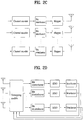
- FIGs. 2C to 2E exemplarily show the transmitting and receiving terminal structures of BICM-ID MCW (multi-codeword).
- FIG. 2C shows an example of a transmitting terminal structure.
- the transmitting terminal structure shown in FIG. 2C differs from the former structure shown in FIG. 2A in performing independently channel encoding, interleaving and mapping on data packet per each antenna layer.
- FIG. 2D shows an example of a receiving terminal structure corresponding to the transmitting terminal structure shown in FIG. 2C .
- the receiving terminal structure shown in FIG. 2D differs from the former structure shown in FIG. 2B in performing independently deinterleaving and extracting the reliability information per each antenna layer like the transmitting terminal shown in FIG. 2C .
- the receiving terminal in FIG. 2D is unable to perform demapping for each antenna layer. Instead, joint detection will be executed for all antenna layers at once by ML (maximum likelihood) detection method.
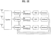
- FIG. 2E shows another example of a receiving terminal structure, which differs from FIG. 2D in including an equalizer in addition.
- data bits can be extracted by performing demapping for each antenna layer using an equalizer capable of using such a detection method as MMSE (minimum mean-square error), ZF (zero-forcing), and the like.
- MMSE minimum mean-square error
- ZF zero-forcing
- FIGS. 3A and 3B are flowcharts according to a first embodiment of the present invention respectively.
- FIG. 3A shows an example of a method of processing a signal in a receiving terminal according to an embodiment of the present invention.
- each OFDM symbol signal transmitted by the transmitting terminal 20 is received via the antenna module 201 included in the receiving terminal 200 (S30).
- the received signal is Fourier-transformed by the FFT 202a.
- the transformed signal i.e., symbol signal is inputted to the demapping module 203.
- the symbol signal is then transformed into a bit signal by the demapping module 203 (S301).
- the reliability information extracting unit receives the bit signal, generates reliability information for the demapped bit signal generated by the demapping module 203, and then delivers the generated reliability information to the demapping module 203 to demapping again using the generated reliability information (S303).
- the demapping module 203 re-executes the demapping by using the received reliability information with an original signal.
- the process for generating the reliability information for each signal and re-executing the demapping for each signal using the generated reliability information corresponding to the each signal is repeated as many as a prescribed count and demapped bit is then outputted (S305, S306).
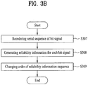
- FIG. 3B shows a detailed flowchart of the step S303 of generating the reliability information to be delivered to the demapping module 203.
- a process for generating reliability information via a reliability information extracting unit is explained with reference to FIG. 3B as follows.
- bit signal generated from the demapping module 203 is inputted to the bit deinterleaver 205 and the order of the interleaved bit sequence is then rearranged to the original order of the bit sequence by the bit deinterleaver 205 (S307).
- the order-rearranged bit sequence is inputted to the SISO (soft-input soft-output) module 206.
- the SISO module 206 generates reliability information using the inputted signal to be delivered to the demapping module 203 (S309).
- the information can be generated using Formula 1.
- the result of Formula 1 indicates an extent of reliability in demapping the inputted symbol signal.
- the extent of reliability may correspond with a probability value that the inputted symbol signal becomes '+1' or '-1'.
- d j i indicates information corresponding to an i th bit of a j th symbol signal.
- the reliability information can be obtained by performing a log operation on a ratio of a probability value that a symbol corresponding to a bit inputted to the SISO module becomes '+1' to a probability value that the symbol corresponding to a bit value inputted to the SISO module becomes '-1'.
- the reliability information generated by the SISO module 206 using Formula 1 is inputted to the bit interleaver 207.
- the bit interleaver 207 then changes an order of the reliability information for the respective inputted bit signals by the method of interleaving the original order of the bit sequence in the interleaver 22 of the transmitting terminal 20 (S309).
- the reliability information rearranged to the original order is delivered to the demapping module 203 (S303).
- the demapping module 203 is able to raise a value of the extent of reliability by demapping a symbol signal with having the inputted reliability information included in a previously inputted symbol signal. If the value of the extent of reliability is raised, it is able to reconstruct an original bit signal from transmitting terminal more accurately. So, performance of the demapping module 203 is enhanced. In other words, instead of demapping, decoding and directly outputting the inputted signal in the FFT 202a, after the course of decoding and demapping, the reliability information is generated and the demapping is carried out on the respective inputted signals using the generated reliability information iteratively.
- Formula 2 indicates a method of calculating the reliability information value by having channel status information additionally included in Formula 1.
- S d i indicates a set of symbols of which an i th bit of bit sequence is 'd'.
- a value of the 'd' can become '+1' or '-1'.
- the demapping and decoding can be iterated as many as a prescribed count.
- value of the reliability information is updated in a manner that the value calculated in a previous iterative process is included in the reliability information value in each iterative process while the above method is iterated.
- An exemplary method of generating the reliability information value updated in Formula 2 is explained with reference to Formula 3 as follows.
- z j indicates a j th symbol signal transmitted by the transmitting terminal
- r j indicates a j th symbol signal received by the receiving terminal
- H j indicates a channel constant in case of a reception via the j th receiving antenna 201.
- 'M' indicates a size of constellation mapping
- N o indicates a complex noise power.
- the result value calculated in Formula 1 is included.
- the transmitted bit signal can be more accurately estimated in a manner of having the reliability information generated by using Formula 1 or Formula 2 included in the corresponding calculation in Formula 3 which is generating the updated reliability information as above mentioned.
- a process for calculating the reliability information again using the demapping result and re-executing demapping using the reliability information is repeated. If this process is repeated, an absolute value of the estimated data bit value is increased. So, it is able to decide data bits more accurately. Thus, a data bit signal, which is estimated after iterating the data bit estimating process as many as a prescribed count, is finally estimated (S306).
- FIGs. 4A to 4E A second embodiment of the present invention is explained with reference to FIGs. 4A to 4E as follows.
- FIGs. 4A to 4E are block diagrams of transmitting terminals and receiving terminals according to a second embodiment of the present invention. The same configurations as shown in FIG. 2A and FIG. 2B are omitted in the following description.
- FIGs. 4A to 4E differ from FIG. 2A and FIG. 2B in including an STBC (space time block code) encoder 45 or an STBC decoder 403.
- the STBC encoder/decoder 45/403 performs coding/decoding of transmitting symbols in time and space to obtain transmission diversity.
- this coding scheme is called STC (space time code) scheme.
- the STC scheme uses spatial and temporal correlations to signals transmitted from different antennas in order for a receiving terminal to provide a perfect diversity effect and a coding gain without sacrificing a bandwidth.
- An example of the STC scheme is STBC (space time block code). In the space time block code, a receiving terminal uses a very simple decoding algorithm.
- Z j indicates a symbol signal transmitted by a j th antenna of a transmitting terminal. If STBC coding is carried out through the code matrix proposed by Formula 4, three symbol signals are transmitted for four time slots.
- the structure of performing STBC coding additionally on BICM-ID capable of performing the aforementioned iterative decoding can be named STBC-BICM-ID.
- STBC coding may be applicable to other STBC structures as well as the above example.
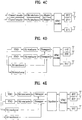
- FIGs. 4C to 4E show transmitting and receiving terminal structure of STBC-BICM-ID MCW (multi code word).
- FIG. 4C shows an example of a structure of a transmitting terminal. Like FIG. 2C , FIG. 4C differs from FIG. 4A in that a data packet from the each antenna of a transmitting terminal is independently encoded, interleaved and mapped per the each antenna layer.
- FIG. 4D shows an example of a receiving terminal structure corresponding to the transmitting terminal shown in FIG. 4C .
- the receiving terminal shown in FIG. 4D is capable of performing decoding per each antenna layer as well as demapping and deinterleaving.
- the demapping can be performed per each antenna layer.
- the receiving terminal is capable of discriminating a signal per antenna using STBC having orthogonal characteristic. So, in case that STBC having no orthogonal characteristic is used, it is unable to perform demapping per the each antenna layer. Instead, ML common detection will be performed at once.
- FIG. 4E shows another example of a receiving terminal structure. Compared to FIG. 4D, FIG. 4E includes an equalizer in addition. In this case, a data symbol can be extracted per each antenna layer using an equalizer capable of using such a detection method as MMSE, ZF, and the like instead of ML detection like the case shown in FIG. 2E .
- an equalizer capable of using such a detection method as MMSE, ZF, and the like instead of ML detection like the case shown in FIG. 2E .
- FIG. 5 is a flowchart according to a second embodiment of the present invention. Operations of a second embodiment of the present invention are explained in detail with reference to FIG. 4A, FIG. 4B , and FIG. 5 as follows.
- each OFDM symbol signal transmitted by a transmitting terminal 40 is received by a receiving terminal 400 via an antenna module 401 included in the receiving terminal 400 (S50).
- the received signal is Fourier-transformed by a FFT 402.
- a FFT 402. By the Fourier transform, a signal on a time domain is transformed into a signal on a frequency domain.
- the Fourier-transformed signal is decoded by an STBC (space time block code) decoder 403 (S500).
- STBC space time block code
- the STBC decoded signal is then inputted to a corresponding demapper 404a included in a demapping module 404.
- An STBC decoded symbol signal is transformed into a bit signal by the demapping module 404 (S502).
- the transformed bit signal that is, a bit sequence is converted from parallel sequence to serial sequence by a parallel/serial converter 405 and then inputted to a bit deinterleaver 406.
- the bit deinterleaver 406 changes an order of the bit sequence into an order prior to interleaving in the transmitting terminal 40.
- the rearranged bit sequence is used to output reliability information for each bit via a soft-input soft-output (SISO) module 407 (S503).
- SISO module 407 is capable of calculating the reliability information by Formula 1.
- the calculated reliability information is inputted to a bit interleaver 408 to change an order of the reliability information for each bit by the same method of changing the order of the bit sequence in the transmitting terminal 40.
- the order-changed reliability information sequence is inputted to the corresponding demapper 404a respectively (S503).
- the demapper re-executes demapping using the reliability information and then outputs a more accurate bit signal (S506).
- a reliability information value for the bit signal is calculated again via the SISO module 407.
- the calculation is carried out using the calculated previous reliability information value.
- estimation of the reliability information value can be made more accurately.
- a demapping process by outputting the above reliability information is repeatedly carried out as many as a prescribed count. Therefore, data bit signal, which is estimated in a manner that the demapping module 404 and the SISO module 407 mutually enhance their functions, is finally estimated and outputted (S506).
- a signal is demodulated using each demapper included in a demapping module wherein the signal is received via at least two antennas. Also, reliability information for each of the demapped bit signals is generated and then delivered to the corresponding demapper again. Hence, decoding performance is enhanced by iterative decoding using the reliability information.
- FIG. 6 is a graph of correlation between a signal to noise ratio (SNR) and a bit error rate (BER).
- SNR signal to noise ratio
- BER bit error rate
- a strength of a signal i.e., a transmission power of a signal may be raised, but an available transmission power for transmission is limited generally.
- the iterative decoding is carried out for the enhancement of the reception performance according to one embodiment of the present invention, it is able to raise the strength of the signal by applying iterative decoding without increment of a transmission power level.
- FIG. 6 shows an iterative decoding executed curve. It can be observed from FIG. 6 that by increasing the strength of the signal through the iterative decoding, a bit error rate is reduced to enhance the reception performance.
- the iterative decoding executed curve can be divided into three regions.
- the iterative decoding executed curve can be divided into a non-convergence region 600, a waterfall (WF) region 601, and an error floor region 602.
- WF waterfall
- the non-convergence region 600 is a region that does not show the explicit performance enhancement despite the application of the iterative decoding.
- a gray mapping mapping rule just having a 1-bit difference between mapping symbols closest to each other shows good performance.
- the WF region 601 is a region in which overall reception performance can be determined through the iterative decoding.
- error floor region 602 is a region where a BER is not considerably changed according to SNR due to performance of a channel encoder.
- a demapper can affect total system performance.
- a coding gain can be increased by optimizing the mapping used for the iterative decoding.
- BICM bit interleaved coded modulation
- An optimized mapping rule can be selected by considering a coding scheme and/or a modulating scheme used in a communication system. For instance, there are various available mapping rules corresponding to modulation schemes such as QPSK, 8PSK, 16QAM, 64QAM, and the like.
- mapping rule As mentioned in the foregoing description, as long as an optimized mapping rule is selected among the various mapping rules and used for the iterative decoding, the performance of a demapper can be enhanced. Furthermore, it will help enhancement of overall system performance. In the following description, examples for a method of selecting a suitable mapping rule from various mapping rules are explained.
- a proper reference may be taken into consideration to select a mapping rule.
- a communication system may be used.
- a mapping rule can be selected according to which one of various communication systems such as BICM, ST-BICM, BICM-ID, STBC-BICM-ID, and the like is used. Since a performance or an effect of the demapper may differ in correspondence to features of a communication system, better reception performance can be expected if an optimized mapping rule is selected by considering the various features of each of the communication systems.
- target performance in correspondence to transmitted data traffic or the aforesaid communication system may be used.
- target performance there is BER (bit error rate), FER (frame error rate), PER (packet error rate), or the like. Since mapping rules bringing good effect may differ according to targeted BER values, a mapping rule can be selected by considering the target performance.
- a mapping rule can be selected by considering an average value for a total bit error, i.e., a mean bit error value which will be explained in detail in the following description. It is more efficient to select and use an optimized mapping rule for each of considerations rather than use a general mapping rule considering various communication systems, target performance or the like.
- Performance of a demapper of a receiving terminal can be expressed as a multiplication between the mean bit error value and a symbol error probability. This is represented as following formula 5. P demap ⁇ N b P e .
- a symbol error probability P e is a function of a harmonic mean of a minimum squared Euclidean distance and SNR in a constellation mapping graph.
- the performance of the demapper of the receiving terminal is associated with a average value for total bit error, i.e., a mean bit error value N b , which can be taken into consideration to select a mapping rule having good performance in the WF region 601.
- N b may not affect the demapper performance, more particularly, performance in the error floor region 602. This is because one bit error can be found for all mapping rules on the assumption that feedback is ideally performed in the error floor region 602.
- p x ( i ) indicates a probability value corresponding to a symbol signal x(i) of an i th (constellation) symbol signal in constellation mapping
- N i indicates a number of points of neighboring constellation mapping of the i th symbol signal x(i), i.e., a number of neighboring constellations
- n b ( i,j ) indicates a number of bit errors that the i th symbol signal x(i) is incorrectly demodulated into a j th symbol signal x(j).
- the mean bit error value is a variable value in correspondence to a given mapping rule.
- a harmonic mean of a minimum Euclidean distance may be used.
- the harmonic mean of the minimum Euclidean distance is a variable corresponding to a distance between a transmission symbol and a received symbol that may be erroneous in a constellation mapping graph.
- An example of a method of deciding a harmonic mean of a minimum Euclidean distance is proposed by Formula 7A.
- Formula "7A is applied to M-antilogarithm constellation mapping.
- 'm' indicates Log 2 (M) and x means a signal subset for each antenna provided in each transmission time on the assumption that x is equal for the transmitting antennas.
- X b i indicates a signal subset grouped into m-bit sequence to configure a symbol for each transmitting antenna. Namely, it indicates a subset that a bit of an i th bit is 'b'. A value of the 'b' can be set to '0' or '1'.
- 'x' indicates a transmitted symbol signal and 'z' indicates an error symbol signal.
- Formula 7B differs from Formula 7A in considering a plurality of receiving antennas.
- 'Nr' indicates a number of receiving antennas. This means that the harmonic mean of the minimum Euclidean distance, i.e., a selected mapping rule may be changed in correspondence to a number of receiving antennas.
- the Euclidean distance can be defined into two cases to select a mapping rule.
- d h 2 (before) and d h 2 (after) are defined as the Euclidean distance before iterative decoding and the Euclidean distance after iterative decoding, respectively.
- d h 2 (before) and d h 2 (after) mean the Euclidean distance of mapping of the non-convergence 600 before executing iterative decoding and the Euclidean distance in the error floor 602 after executing iterative decoding, respectively.
- mapping rule an example of a method of selecting a mapping rule is explained by referring to the examples of the references to be considerated to select the mapping rule.
- a plurality of mapping rules may be grouped into at least one group according to a specific reference.
- the specific reference may be one or more of the communication system, the target performance (e.g., BER value), the mean bit error value, and the like. Since each of at least one group may correspond to the plurality of the mapping rules, we can select a suitable group and then a mapping rule may be selected from the selected group. Thus, a search area for selecting a mapping rule can be reduced as well as a time taken to select a mapping rule.
- d h 2 (before), d h 2 (after), and N b are calculated using Formula 6 and Formula 7A or Formula 7B for an optimized constellation mapping.
- Available mapping rules are grouped into at least one group according to the calculated N b .
- the at least one mapping rule having the biggest d h 2 (after) is selected from each of the groups.
- a mapping rule having the biggest d h 2 (before) is selected from the mapping rules selected as having the biggest d h 2 (after).
- a mapping rule having best performance by tests according to a configuration of a system may be selected as a mapping rule having the biggest d h 2 (before).
- an optimized mapping rule can be selected by the following process.
- the graph shown in FIG. 6 can be differently represented according to a type of the mapping. In particular, there could be a variation of a slope of the BER curve or the like according to what kind of mapping rule is used in executing mapping or demapping.
- the variation changes the SNR to which the error floor region 602 corresponds. As the SNR to which the error floor region 602 corresponds gets smaller, so the performance becomes better. As the SNR in which the error floor region 602 corresponding to the targeted BER exists gets smaller, the performance of decoding gets better.
- FIG. 7 is an exemplary diagram of 8PSK constellation mapping rule according to one preferred embodiment of the present invention.
- the exemplary optimized mapping rule among the groups is the mapping rule shown in FIG. 7 .
- mapping rule by which binary codes of a mapping rule are decided in order of 000, 001, 011, 010, 110, 111, 101, and 100 counterclockwise, proposed by (a) of FIG. 7 shows the best performance.
- mapping rule by which binary codes of a mapping rule are decided in order of 000, 001, 111, 110, 100, 101, 011, 010 counterclockwise, proposed by (b) of FIG. 7 shows the best performance.
- mapping rule by which binary codes of a mapping rule are decided in order of 000, 001, 111, 100, 110, 101, 011, 010 counterclockwise, proposed by (c) of FIG. 7 shows the best performance.
- mapping rule by which binary codes of a mapping rule are decided in order of 000, 001, 111, 100, 010, 011, 101, 110 counterclockwise, proposed by (d) of FIG. 7 shows the best performance.
- mapping rule by which binary codes of a preset mapping rule are decided in order of 000, 010, 111, 100, 001, 110, 011, 101 counterclockwise, proposed by (e) of FIG. 7 shows the best performance.
- mapping rule by which binary codes of a mapping rule are decided in order of 000, 101, 010, 111, 100, 001, 110, 011 counterclockwise, proposed by (f) of FIG. 7 shows the best performance.
- FIG. 8 is an exemplary diagram of 16QAM constellation mapping rule according to one preferred embodiment of the present invention.
- mapping rules having the good performance of each group are those shown in FIG. 8 .
- the corresponding mapping rules include "Mixed Labeling"(a), “Random Labeling”(b), “Gray Labeling”(c), “Maximum SEW Labeling”(d), “M16 r Labeling”(e), “Modified SP Labeling”(f), etc.
- the arrangement of the binary codes in each of the mapping rules is shown in FIG. 8 .
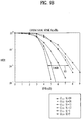
- FIG. 9A and FIG. 9B are graphs for effects of one preferred embodiment of the present invention.
- FIG. 9A is a performance graph in case of applying iterative decoding to a space time block coded orthogonal frequency division multiplexing system. It can be observed that system performance is enhanced through optimization of a used mapping rule by applying iterative decoding without transmission power increment in a same channel environment.
- the graph shown in FIG. 9A indicates a result in case of using STBC (3/4 rate orthogonal STBC) in the exponentially decaying Rayleigh fading channel environment when there exist 12 multi-paths by applying the 8PSK mapping rule.
- FIG. 9B shows an execution result when a code rate is 4/9 in a different channel status.
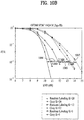
- FIG. 10A and FIG. 10B are graphs for effects of one preferred embodiment of the present invention.
- FIG. 10A is a performance graph in case of applying iterative decoding to a space time block coded orthogonal frequency division multiplexing system. It can be observed that system performance is enhanced through optimization of a used mapping rule by applying iterative decoding without transmission power increment in a same channel environment.
- the graph shown in FIG. 10A indicates a result in case of using STBC (3/4 rate orthogonal STBC) in the exponentially decaying Rayleigh fading channel environment when there exist 12 multi-paths by applying the 16QAM mapping rule.
- FIG. 10B shows an execution result of a convolution code using the same modulation scheme when a code rate is 2/3 in various channel states. It is assumed that a channel has 5, 12, 20 tab (multi-path). Compared to the case of using the gray mapping (mapping having 1-bit difference between closest mapping symbols), the case of using the mapping rule of 'Random Labeling' among the various mapping rules has gains 2.5dB, 2.7dB, and 3dB for the respective channel numbers (1005, 1004, 1003). Similar to the case of 8PSK, the present case shows that a gain of a mapping rule having better performance in correspondence to the incremented channel number is increased.
- a gain resulted from an optimized mapping rule is increased according to an increased code rate.
- a system variable as a code rate, a modulation level, and the like is determined, it can be observed that a mapping rule having the best performance does not vary without being affected by a changed channel status.
- the optimized mapping rule can be sustained regardless of the channel variation.
- the mapping rule having the optimal performance for the various channel statuses and transmission efficiencies can be fixed. So, once the mapping rule having the best performance is proposed, the mapping rule is intactly applicable to various channel statues to show the best performance.
- an interleaving rule or permutation rule is adaptively applicable.
- interleaving means that the coded bits in form of bit sequence are disperse by a prescribed bit unit and that bits are independently arranged, to reduce burst error and effect of fading.
- permutation means that coded and modulated data is allocated to each subcarrier in an OFDMA (orthogonal frequency division multiple access) system.
- OFDMA orthogonal frequency division multiple access
- permutation there is FUSC (full usage of subcarriers) of allocating subcarriers within a transmission unit as a whole and PUSC (partial usage of subcarriers) of allocating subcarriers within a transmission unit by dividing them into at least one.
- the interleaving or permutation is executed according to a prescribed rule.
- the interleaving rule and/or permutation rule can be adaptively selected or changed to be used. Coding, interleaving, mapping, permutation, and the like are sequentially executable for a single communication process. Therefore, they can be associated with each other. In case that a mapping rule is adaptively usable, if rules used for other processes are adaptively usable, communication efficiency can be further enhanced.
- the rules used in at least one communication module could be adaptively selected and used, the rules can be grouped for better effects. For instance, in case that 1/2 convolution code and 8PSK modulation are used as modulation and coding scheme (MCS) respectively, it is assumed that the mapping rule shown in (b) of FIG. 7 is selected to be used. In this case, since a specific interleaving rule and/or a specific permutation rule are preset to be used on a system, if a mapping rule is selected, a suitable specific interleaving rule and or a suitable specific permutation rule can be used according to the selected mapping rule.
- MCS modulation and coding scheme
- mapping rule After a mapping rule has been selected, it is able to use rules having good performance without deciding an interleaving rule and/or a permutation rule one by one. This can be advantageous in reducing signaling overhead in aspect of signaling, which is be explained as follows.
- information for an optimized mapping rule in a system using a method for selecting to use a suitable mapping rule can be informed.
- Informing downlink of the information for an optimized mapping rule selected in a system shall be named 'signaling' in the following description.
- a signaling method there is a method of assigning indexes to available mapping rules and transmitting index information corresponding to a selected mapping rule. For instance, in case that there are total 8 available mapping rules, total 3 bits are allocated to signaling information bits for the mapping rules and indexes 000 to 111 are assigned to the total 8 available mapping rules, respectively. So, as a result of selection, if the mapping rule corresponding to the index 101 is selected, signaling information corresponding to the index 101 can be transmitted.
- mapping rule As another example of a signaling method, there is a method of connecting a mapping rule to another signaling information correlated to the mapping rule. For instance, correlations between MCS and corresponding mapping rules are preset in a system. And, it can be only informed whether a mapping rule correlated to a decided MCS is used. In particular, in case that a third MCS is used, it is assumed that the mapping rule shown in (c) of FIG. 7 is decided to be selected. In case that a fourth MCS is used, it is assumed that the mapping rule shown in (d) of FIG. 7 is decided to be selected.
- the system may indicate the information for the mapping rule in a manner of transmitting signaling information of '1' for the case of using the mapping rule shown in (c) of FIG. 7 or signaling information of '0' for the case of not using the mapping rule shown in (c) of FIG. 7 , using 1 bit as a signaling information bit for informing the mapping rule.
- mapping rule in case of using a coding rule and/or a permutation rule adaptively according to a mapping rule, information for the coding rule, the interleaving rule and/or the permutation rule can be informed by the method similar to that used for the signaling of the mapping rule.
- the present invention is suitable for a wide scope of applications, it is particularly suitable for mapping a transmission signal more effectively and decoding a received signal in case of transceiving signals using a multi-antenna.
- the present invention provides the following effects or advantages.
- communication can be efficiently performed by enhancing performance of transmitting and receiving terminals in a mobile communication system.
- diversity is more effectively provided in multi-antenna transmission, whereby effect on channel variation can be reduced.
- the present invention enhances performance of a decoder, thereby increasing a coding gain.
Landscapes
- Engineering & Computer Science (AREA)
- Computer Networks & Wireless Communication (AREA)
- Signal Processing (AREA)
- Power Engineering (AREA)
- Quality & Reliability (AREA)
- Radio Transmission System (AREA)
- Error Detection And Correction (AREA)
Claims (10)
- Verfahren zum Verarbeiten eines Signals in einem mit einer Mehrzahl von Antennen versehenen Empfangsendgerät, das Verfahren umfassend:Rückabbilden eines über die Mehrzahl von Antennen empfangenen Symbolsignals zu einem Bitsignal nach einer adaptiv festgelegten und in einem Übertragungsendgerät verwendeten Abbildungsregel;Extrahieren von Zuverlässigkeitsinformationen für das aus der Rückabbildung gewonnene Bitsignal; underneutes Durchführen der Rückabbildung des Symbolsignals unter Verwendung der Zuverlässigkeitsinformationen,dadurch gekennzeichnet, dass:die Abbildungsregel aus mindestens einer Abbildungsgruppe ausgewählt wird, die unter Verwendung eines mittleren Bitfehlerwertes jeder der verfügbaren Abbildungsregeln gebildet wird, unddas Extrahieren der Zuverlässigkeitsinformationen und das erneute Durchführen der Rückabbildung jeweils so oft wie eine vorgegebene Zahl auf der Grundlage der festgelegten Abbildungsregel wiederholt werden.
- Verfahren nach Anspruch 1, wobei das Symbolsignal unter Verwendung eines Raum-Zeit-Blockcodes, STBC, kodiert und vom Übertragungsendgerät übertragen wird.
- Verfahren nach Anspruch 2, ferner umfassend den Schritt der Dekodierung des Symbolsignals unter Verwendung des Raum-Zeit-Blockcodes, STBC.
- Verfahren nach Anspruch 1, wobei die Zuverlässigkeitsinformationen einem Verhältnis einer Wahrscheinlichkeit, dass das Bitsignal "0" wird, zu einer Wahrscheinlichkeit, dass das Bitsignal "1" wird, entsprechen.
- Verfahren nach Anspruch 1, wobei die Abbildungsregel unter Verwendung des mittleren Bitfehlerwertes und eines harmonischen Mittels des minimalen euklidischen Abstands einer Abbildungsregel festgelegt wird.
- Verfahren nach Anspruch 1, wobei die Abbildungsregel festgelegt wird durch:Berechnen des mittleren Bitfehlerwertes, eines harmonischen Mittels eines minimalen euklidischen Abstands in einem Fehlerboden und eines harmonischen Nicht-Konvergenz-Mittels eines minimalen euklidischen Abstands für jede der verfügbaren Abbildungsregeln,Aufteilen der verfügbaren Abbildungsregeln in die mindestens eine Abbildungsgruppe mit Bezug auf den mittleren Bitfehlerwert,erstens Auswählen mindestens einer Abbildungsregel mit dem größten harmonischen Mittel des minimalen euklidischen Abstands im Fehlerboden innerhalb jeder der mindestens einen Abbildungsgruppe undzweitens Auswählen mindestens einer Abbildungsregel mit dem größten harmonischen Nicht-Konvergenz-Mittel des minimalen euklidischen Abstands aus der ersten ausgewählten mindestens einen Abbildungsregel.
- Verfahren nach Anspruch 1, wobei beim Modulieren der Abbildungsregel durch ein 8PSK-Schema binäre Codes einer vorgegebenen Abbildungsregel in der Reihenfolge 000, 001, 111, 100, 010, 011, 101 und 110 entgegen dem Uhrzeigersinn festgelegt werden.
- Verfahren nach Anspruch 1, wobei das Signalisieren von Informationen für die Abbildung entweder unter Verwendung von Indexinformationen für die Abbildungsregel oder von Informationen darüber, ob die anderen Signalisierungsinformationen entsprechende Abbildungsregel verwendet wird, durchgeführt wird.
- Verfahren nach Anspruch 1, wobei eine Anzahl der Mehrzahl von Antennen, mit denen das Empfangsendgerät versehen ist, bei der Festlegung der Abbildungsregel berücksichtigt wird.
- Empfangsvorrichtung mit einer Mehrzahl von Antennen, die Empfangsvorrichtung umfassend:ein Rückabbildungsmodul, das ein Bitsignal erhält, das durch Durchführen der Rückabbildung eines Symbolsignals, das über die Mehrzahl von Antennen nach einer adaptiv festgelegten und in einem Übertragungsendgerät verwendeten Abbildungsregel empfangen wird, und erneutes Durchführen der Rückabbildung des Symbolsignals unter Verwendung von Zuverlässigkeitsinformationen für das Bitsignal geschätzt wird; undeine Zuverlässigkeitsinformationen extrahierende Einheit, die die Zuverlässigkeitsinformationen durch Empfangen des geschätzten Bitsignals vom Rückabbildungsmodul extrahiert und die extrahierten Zuverlässigkeitsinformationen an das Rückabbildungsmodul liefert,dadurch gekennzeichnet, dass:die Abbildungsregel aus mindestens einer Abbildungsgruppe ausgewählt wird, die unter Verwendung eines mittleren Bitfehlerwertes jeder der verfügbaren Abbildungsregeln gebildet wird, unddas Rückabbildungsmodul und die Zuverlässigkeitsinformationen extrahierende Einheit das erneute Durchführen der Rückabbildung und Extrahieren der Zuverlässigkeitsinformationen jeweils so oft wie eine vorgegebene Zahl auf der Grundlage der festgelegten Abbildungsregel wiederholen.
Applications Claiming Priority (2)
| Application Number | Priority Date | Filing Date | Title |
|---|---|---|---|
| KR20060046083 | 2006-05-23 | ||
| PCT/KR2007/002517 WO2007136232A2 (en) | 2006-05-23 | 2007-05-23 | Apparatus for processing received signal, method thereof, and method for selecting mapping rule |
Publications (3)
| Publication Number | Publication Date |
|---|---|
| EP2030341A2 EP2030341A2 (de) | 2009-03-04 |
| EP2030341A4 EP2030341A4 (de) | 2013-08-07 |
| EP2030341B1 true EP2030341B1 (de) | 2017-03-29 |
Family
ID=38723714
Family Applications (1)
| Application Number | Title | Priority Date | Filing Date |
|---|---|---|---|
| EP07746665.4A Not-in-force EP2030341B1 (de) | 2006-05-23 | 2007-05-23 | Vorrichtung zum verarbeiten eines empfangssignals, verfahren dafür und verfahren zur auswahl einer abbildungsregel |
Country Status (5)
| Country | Link |
|---|---|
| US (1) | US8472565B2 (de) |
| EP (1) | EP2030341B1 (de) |
| KR (1) | KR101341524B1 (de) |
| CN (1) | CN101542939B (de) |
| WO (1) | WO2007136232A2 (de) |
Families Citing this family (16)
| Publication number | Priority date | Publication date | Assignee | Title |
|---|---|---|---|---|
| WO2008147123A1 (en) * | 2007-05-29 | 2008-12-04 | Samsung Electronics Co., Ltd. | Apparatus and method for mapping symbols to resources in a mobile communication system |
| EP2153561B1 (de) | 2007-06-05 | 2019-01-09 | Constellation Designs, Inc. | Verfahren und vorrichtung zur signalisierung mit kapazitätsoptimierten konstellationen |
| US9191148B2 (en) | 2007-06-05 | 2015-11-17 | Constellation Designs, Inc. | Methods and apparatuses for signaling with geometric constellations in a Raleigh fading channel |
| US8265175B2 (en) | 2007-06-05 | 2012-09-11 | Constellation Designs, Inc. | Methods and apparatuses for signaling with geometric constellations |
| CN102150406A (zh) * | 2008-09-12 | 2011-08-10 | 夏普株式会社 | 无线通信系统、无线通信方法以及通信装置 |
| KR101644434B1 (ko) * | 2009-02-22 | 2016-08-01 | 엘지전자 주식회사 | 하향링크 mimo시스템에 있어서, 하향링크 신호 생성 방법 |
| US20110090820A1 (en) | 2009-10-16 | 2011-04-21 | Osama Hussein | Self-optimizing wireless network |
| CN102546080B (zh) * | 2010-12-21 | 2014-06-25 | 华为技术有限公司 | 一种下行基带信号生成方法及相关设备、系统 |
| EP2754271B1 (de) | 2011-09-09 | 2019-11-13 | Reverb Networks Inc. | Verfahren und vorrichtung zur implementierung eines selbstorganisierenden und -optimierenden netzwerkmanagers |
| US9258719B2 (en) | 2011-11-08 | 2016-02-09 | Viavi Solutions Inc. | Methods and apparatus for partitioning wireless network cells into time-based clusters |
| US9008722B2 (en) * | 2012-02-17 | 2015-04-14 | ReVerb Networks, Inc. | Methods and apparatus for coordination in multi-mode networks |
| US8995320B2 (en) * | 2012-04-16 | 2015-03-31 | Qualcomm Incorporated | Systems and methods of using space time block codes |
| CN103516465B (zh) * | 2012-06-21 | 2017-04-26 | 华为技术有限公司 | 编码调制和解调译码方法、装置及系统 |
| CA3024609C (en) * | 2014-05-09 | 2020-04-07 | Electronics And Telecommunications Research Institute | Signal multiplexing apparatus using layered division multiplexing and signal multiplexing method |
| US9113353B1 (en) | 2015-02-27 | 2015-08-18 | ReVerb Networks, Inc. | Methods and apparatus for improving coverage and capacity in a wireless network |
| CN109672466B (zh) * | 2018-12-12 | 2022-02-18 | 广州极飞科技股份有限公司 | 信号数据处理方法、装置、计算机设备及存储介质 |
Family Cites Families (14)
| Publication number | Priority date | Publication date | Assignee | Title |
|---|---|---|---|---|
| WO2001065760A1 (en) * | 2000-03-01 | 2001-09-07 | Nokia Corporation | Concatenated space-time coding |
| US20020193146A1 (en) * | 2001-06-06 | 2002-12-19 | Mark Wallace | Method and apparatus for antenna diversity in a wireless communication system |
| JP3815344B2 (ja) * | 2002-02-21 | 2006-08-30 | 株式会社日立製作所 | 多値変調に適した符号語マッピング方法 |
| US7095709B2 (en) | 2002-06-24 | 2006-08-22 | Qualcomm, Incorporated | Diversity transmission modes for MIMO OFDM communication systems |
| US7359313B2 (en) * | 2002-06-24 | 2008-04-15 | Agere Systems Inc. | Space-time bit-interleaved coded modulation for wideband transmission |
| WO2005029758A2 (en) * | 2003-09-15 | 2005-03-31 | Intel Corporation | Multiple antenna systems and methods using high-throughput space-frequency block codes |
| US7724838B2 (en) * | 2003-09-25 | 2010-05-25 | Qualcomm Incorporated | Hierarchical coding with multiple antennas in a wireless communication system |
| US7746886B2 (en) | 2004-02-19 | 2010-06-29 | Broadcom Corporation | Asymmetrical MIMO wireless communications |
| KR100714973B1 (ko) | 2004-08-16 | 2007-05-04 | 삼성전자주식회사 | 하이브리드 자동재전송요구 시스템에서 신호점 사상규칙을변경하기 위한 장치 및 방법 |
| KR101151130B1 (ko) | 2004-08-17 | 2012-06-04 | 삼성전자주식회사 | 완전 다이버시티 완전 데이터 레이트 시공간 블록 부호를 이용한 데이터 송수신 방법 및 장치 |
| KR20070085471A (ko) * | 2004-11-05 | 2007-08-27 | 유니버시티 오브 플로리다 리서치 파운데이션, 인크. | Mimo 통신을 위한 균일 채널 분해 |
| WO2006099267A2 (en) * | 2005-03-14 | 2006-09-21 | Telcordia Technologies, Inc. | Iterative mimo receiver using group-wise demapping |
| KR20060106223A (ko) * | 2005-04-06 | 2006-10-12 | 삼성전자주식회사 | 직교 주파수 분할 다중 시스템에서 비트 삽입 및 코드 변조방식의 송신 장치 및 방법 |
| US7526705B2 (en) * | 2005-05-03 | 2009-04-28 | Agere Systems Inc. | Acknowledgement message modification in communication networks |
-
2007
- 2007-05-23 CN CN200780019017XA patent/CN101542939B/zh not_active Expired - Fee Related
- 2007-05-23 EP EP07746665.4A patent/EP2030341B1/de not_active Not-in-force
- 2007-05-23 US US12/301,953 patent/US8472565B2/en not_active Expired - Fee Related
- 2007-05-23 WO PCT/KR2007/002517 patent/WO2007136232A2/en active Application Filing
-
2008
- 2008-12-03 KR KR1020087029598A patent/KR101341524B1/ko not_active IP Right Cessation
Non-Patent Citations (1)
| Title |
|---|
| None * |
Also Published As
| Publication number | Publication date |
|---|---|
| EP2030341A4 (de) | 2013-08-07 |
| US20100303174A1 (en) | 2010-12-02 |
| WO2007136232A3 (en) | 2009-06-04 |
| KR20090013220A (ko) | 2009-02-04 |
| US8472565B2 (en) | 2013-06-25 |
| CN101542939A (zh) | 2009-09-23 |
| EP2030341A2 (de) | 2009-03-04 |
| CN101542939B (zh) | 2012-11-28 |
| WO2007136232A2 (en) | 2007-11-29 |
| KR101341524B1 (ko) | 2013-12-16 |
Similar Documents
| Publication | Publication Date | Title |
|---|---|---|
| EP2030341B1 (de) | Vorrichtung zum verarbeiten eines empfangssignals, verfahren dafür und verfahren zur auswahl einer abbildungsregel | |
| US10411783B2 (en) | System and method for mapping symbols for MIMO transmission | |
| JP4490922B2 (ja) | マルチアンテナ送信装置及びマルチアンテナ送信方法 | |
| KR100688120B1 (ko) | 무선통신시스템에서 시공간 주파수 블록 부호화 장치 및방법 | |
| JP4436415B2 (ja) | 性能向上のための時空間周波数ブロック符号化装置及び方法 | |
| EP2426844B1 (de) | Verbesserte MIMO-Kommunikation | |
| US7539261B2 (en) | Multi-layer coded modulation for non-ergodic block fading channels | |
| US20110320920A1 (en) | Coding apparatus, receiving apparatus, wireless communication system, puncturing pattern selecting method and program thereof | |
| CN101006658A (zh) | 用于时空频率分组编码以提高性能的装置和方法 | |
| KR20060043799A (ko) | 성능 향상위한 시공간 블록 부호화 장치 및 방법을 구현하는 송수신 장치 및 방법 | |
| CN101141166A (zh) | 数据发送装置 | |
| US20070127593A1 (en) | Apparatus and method for transmitting/receiving a signal in a communication system | |
| US8139668B2 (en) | Unified STTC encoder for WAVE transceivers | |
| JP4510870B2 (ja) | 無線通信方法及び無線通信装置 | |
| KR20070038375A (ko) | 다수개의 송신 안테나들을 사용하는 직교 주파수 분할다중화/직교 주파수 분할 다중 접속 통신 시스템에서 신호송수신 장치 및 방법 | |
| Lu et al. | A space-time trellis code design method for OFDM systems | |
| Arunachalam et al. | Space-time coding for MIMO systems with co-channel interference | |
| El Gamal et al. | Space-time coding techniques for MIMO block fading channels with co-channel interference | |
| KR101276838B1 (ko) | 시공간 부호를 이용하여 신호를 송신하는 방법 | |
| WO2009020297A1 (en) | Method of transmitting data in wireless communication system | |
| Cho et al. | Improvement of the throughput-SNR trade-off using a 4G adaptive MCM system |
Legal Events
| Date | Code | Title | Description |
|---|---|---|---|
| PUAI | Public reference made under article 153(3) epc to a published international application that has entered the european phase |
Free format text: ORIGINAL CODE: 0009012 |
|
| 17P | Request for examination filed |
Effective date: 20081215 |
|
| AK | Designated contracting states |
Kind code of ref document: A2 Designated state(s): AT BE BG CH CY CZ DE DK EE ES FI FR GB GR HU IE IS IT LI LT LU LV MC MT NL PL PT RO SE SI SK TR |
|
| AX | Request for extension of the european patent |
Extension state: AL BA HR MK RS |
|
| R17D | Deferred search report published (corrected) |
Effective date: 20090604 |
|
| DAX | Request for extension of the european patent (deleted) | ||
| A4 | Supplementary search report drawn up and despatched |
Effective date: 20130705 |
|
| RIC1 | Information provided on ipc code assigned before grant |
Ipc: H04B 7/06 20060101ALI20130701BHEP Ipc: H04L 1/00 20060101ALI20130701BHEP Ipc: H04L 27/26 20060101ALN20130701BHEP Ipc: H04L 25/06 20060101ALI20130701BHEP Ipc: H04B 7/08 20060101AFI20130701BHEP Ipc: H04L 1/06 20060101ALI20130701BHEP |
|
| GRAP | Despatch of communication of intention to grant a patent |
Free format text: ORIGINAL CODE: EPIDOSNIGR1 |
|
| STAA | Information on the status of an ep patent application or granted ep patent |
Free format text: STATUS: GRANT OF PATENT IS INTENDED |
|
| RIC1 | Information provided on ipc code assigned before grant |
Ipc: H04B 7/08 20060101AFI20161103BHEP Ipc: H04B 7/06 20060101ALI20161103BHEP Ipc: H04L 1/06 20060101ALI20161103BHEP Ipc: H04L 25/06 20060101ALI20161103BHEP Ipc: H04L 1/00 20060101ALI20161103BHEP Ipc: H04L 27/26 20060101ALN20161103BHEP |
|
| INTG | Intention to grant announced |
Effective date: 20161123 |
|
| GRAS | Grant fee paid |
Free format text: ORIGINAL CODE: EPIDOSNIGR3 |
|
| GRAA | (expected) grant |
Free format text: ORIGINAL CODE: 0009210 |
|
| STAA | Information on the status of an ep patent application or granted ep patent |
Free format text: STATUS: THE PATENT HAS BEEN GRANTED |
|
| AK | Designated contracting states |
Kind code of ref document: B1 Designated state(s): AT BE BG CH CY CZ DE DK EE ES FI FR GB GR HU IE IS IT LI LT LU LV MC MT NL PL PT RO SE SI SK TR |
|
| REG | Reference to a national code |
Ref country code: GB Ref legal event code: FG4D |
|
| REG | Reference to a national code |
Ref country code: CH Ref legal event code: EP |
|
| REG | Reference to a national code |
Ref country code: AT Ref legal event code: REF Ref document number: 880644 Country of ref document: AT Kind code of ref document: T Effective date: 20170415 |
|
| REG | Reference to a national code |
Ref country code: IE Ref legal event code: FG4D |
|
| REG | Reference to a national code |
Ref country code: DE Ref legal event code: R096 Ref document number: 602007050390 Country of ref document: DE |
|
| PG25 | Lapsed in a contracting state [announced via postgrant information from national office to epo] |
Ref country code: FI Free format text: LAPSE BECAUSE OF FAILURE TO SUBMIT A TRANSLATION OF THE DESCRIPTION OR TO PAY THE FEE WITHIN THE PRESCRIBED TIME-LIMIT Effective date: 20170329 Ref country code: LT Free format text: LAPSE BECAUSE OF FAILURE TO SUBMIT A TRANSLATION OF THE DESCRIPTION OR TO PAY THE FEE WITHIN THE PRESCRIBED TIME-LIMIT Effective date: 20170329 Ref country code: GR Free format text: LAPSE BECAUSE OF FAILURE TO SUBMIT A TRANSLATION OF THE DESCRIPTION OR TO PAY THE FEE WITHIN THE PRESCRIBED TIME-LIMIT Effective date: 20170630 |
|
| PGFP | Annual fee paid to national office [announced via postgrant information from national office to epo] |
Ref country code: GB Payment date: 20170517 Year of fee payment: 11 Ref country code: DE Payment date: 20170511 Year of fee payment: 11 |
|
| REG | Reference to a national code |
Ref country code: NL Ref legal event code: MP Effective date: 20170329 |
|
| REG | Reference to a national code |
Ref country code: AT Ref legal event code: MK05 Ref document number: 880644 Country of ref document: AT Kind code of ref document: T Effective date: 20170329 |
|
| PG25 | Lapsed in a contracting state [announced via postgrant information from national office to epo] |
Ref country code: BG Free format text: LAPSE BECAUSE OF FAILURE TO SUBMIT A TRANSLATION OF THE DESCRIPTION OR TO PAY THE FEE WITHIN THE PRESCRIBED TIME-LIMIT Effective date: 20170629 Ref country code: SE Free format text: LAPSE BECAUSE OF FAILURE TO SUBMIT A TRANSLATION OF THE DESCRIPTION OR TO PAY THE FEE WITHIN THE PRESCRIBED TIME-LIMIT Effective date: 20170329 Ref country code: LU Free format text: LAPSE BECAUSE OF NON-PAYMENT OF DUE FEES Effective date: 20170531 Ref country code: LV Free format text: LAPSE BECAUSE OF FAILURE TO SUBMIT A TRANSLATION OF THE DESCRIPTION OR TO PAY THE FEE WITHIN THE PRESCRIBED TIME-LIMIT Effective date: 20170329 |
|
| PG25 | Lapsed in a contracting state [announced via postgrant information from national office to epo] |
Ref country code: NL Free format text: LAPSE BECAUSE OF FAILURE TO SUBMIT A TRANSLATION OF THE DESCRIPTION OR TO PAY THE FEE WITHIN THE PRESCRIBED TIME-LIMIT Effective date: 20170329 |
|
| PG25 | Lapsed in a contracting state [announced via postgrant information from national office to epo] |
Ref country code: IT Free format text: LAPSE BECAUSE OF FAILURE TO SUBMIT A TRANSLATION OF THE DESCRIPTION OR TO PAY THE FEE WITHIN THE PRESCRIBED TIME-LIMIT Effective date: 20170329 Ref country code: SK Free format text: LAPSE BECAUSE OF FAILURE TO SUBMIT A TRANSLATION OF THE DESCRIPTION OR TO PAY THE FEE WITHIN THE PRESCRIBED TIME-LIMIT Effective date: 20170329 Ref country code: EE Free format text: LAPSE BECAUSE OF FAILURE TO SUBMIT A TRANSLATION OF THE DESCRIPTION OR TO PAY THE FEE WITHIN THE PRESCRIBED TIME-LIMIT Effective date: 20170329 Ref country code: CZ Free format text: LAPSE BECAUSE OF FAILURE TO SUBMIT A TRANSLATION OF THE DESCRIPTION OR TO PAY THE FEE WITHIN THE PRESCRIBED TIME-LIMIT Effective date: 20170329 Ref country code: RO Free format text: LAPSE BECAUSE OF FAILURE TO SUBMIT A TRANSLATION OF THE DESCRIPTION OR TO PAY THE FEE WITHIN THE PRESCRIBED TIME-LIMIT Effective date: 20170329 Ref country code: ES Free format text: LAPSE BECAUSE OF FAILURE TO SUBMIT A TRANSLATION OF THE DESCRIPTION OR TO PAY THE FEE WITHIN THE PRESCRIBED TIME-LIMIT Effective date: 20170329 Ref country code: AT Free format text: LAPSE BECAUSE OF FAILURE TO SUBMIT A TRANSLATION OF THE DESCRIPTION OR TO PAY THE FEE WITHIN THE PRESCRIBED TIME-LIMIT Effective date: 20170329 |
|
| PG25 | Lapsed in a contracting state [announced via postgrant information from national office to epo] |
Ref country code: IS Free format text: LAPSE BECAUSE OF FAILURE TO SUBMIT A TRANSLATION OF THE DESCRIPTION OR TO PAY THE FEE WITHIN THE PRESCRIBED TIME-LIMIT Effective date: 20170729 Ref country code: PT Free format text: LAPSE BECAUSE OF FAILURE TO SUBMIT A TRANSLATION OF THE DESCRIPTION OR TO PAY THE FEE WITHIN THE PRESCRIBED TIME-LIMIT Effective date: 20170731 Ref country code: PL Free format text: LAPSE BECAUSE OF FAILURE TO SUBMIT A TRANSLATION OF THE DESCRIPTION OR TO PAY THE FEE WITHIN THE PRESCRIBED TIME-LIMIT Effective date: 20170329 |
|
| REG | Reference to a national code |
Ref country code: CH Ref legal event code: PL |
|
| REG | Reference to a national code |
Ref country code: DE Ref legal event code: R097 Ref document number: 602007050390 Country of ref document: DE |
|
| PG25 | Lapsed in a contracting state [announced via postgrant information from national office to epo] |
Ref country code: MC Free format text: LAPSE BECAUSE OF FAILURE TO SUBMIT A TRANSLATION OF THE DESCRIPTION OR TO PAY THE FEE WITHIN THE PRESCRIBED TIME-LIMIT Effective date: 20170329 Ref country code: DK Free format text: LAPSE BECAUSE OF FAILURE TO SUBMIT A TRANSLATION OF THE DESCRIPTION OR TO PAY THE FEE WITHIN THE PRESCRIBED TIME-LIMIT Effective date: 20170329 |
|
| PLBE | No opposition filed within time limit |
Free format text: ORIGINAL CODE: 0009261 |
|
| STAA | Information on the status of an ep patent application or granted ep patent |
Free format text: STATUS: NO OPPOSITION FILED WITHIN TIME LIMIT |
|
| REG | Reference to a national code |
Ref country code: IE Ref legal event code: MM4A |
|
| PG25 | Lapsed in a contracting state [announced via postgrant information from national office to epo] |
Ref country code: LI Free format text: LAPSE BECAUSE OF NON-PAYMENT OF DUE FEES Effective date: 20170531 Ref country code: CH Free format text: LAPSE BECAUSE OF NON-PAYMENT OF DUE FEES Effective date: 20170531 |
|
| REG | Reference to a national code |
Ref country code: FR Ref legal event code: ST Effective date: 20180131 |
|
| 26N | No opposition filed |
Effective date: 20180103 |
|
| PG25 | Lapsed in a contracting state [announced via postgrant information from national office to epo] |
Ref country code: LU Free format text: LAPSE BECAUSE OF NON-PAYMENT OF DUE FEES Effective date: 20170523 |
|
| REG | Reference to a national code |
Ref country code: BE Ref legal event code: MM Effective date: 20170531 |
|
| PG25 | Lapsed in a contracting state [announced via postgrant information from national office to epo] |
Ref country code: IE Free format text: LAPSE BECAUSE OF NON-PAYMENT OF DUE FEES Effective date: 20170523 |
|
| PG25 | Lapsed in a contracting state [announced via postgrant information from national office to epo] |
Ref country code: SI Free format text: LAPSE BECAUSE OF FAILURE TO SUBMIT A TRANSLATION OF THE DESCRIPTION OR TO PAY THE FEE WITHIN THE PRESCRIBED TIME-LIMIT Effective date: 20170329 Ref country code: FR Free format text: LAPSE BECAUSE OF NON-PAYMENT OF DUE FEES Effective date: 20170531 |
|
| PG25 | Lapsed in a contracting state [announced via postgrant information from national office to epo] |
Ref country code: BE Free format text: LAPSE BECAUSE OF NON-PAYMENT OF DUE FEES Effective date: 20170531 |
|
| PG25 | Lapsed in a contracting state [announced via postgrant information from national office to epo] |
Ref country code: MT Free format text: LAPSE BECAUSE OF NON-PAYMENT OF DUE FEES Effective date: 20170523 |
|
| REG | Reference to a national code |
Ref country code: DE Ref legal event code: R119 Ref document number: 602007050390 Country of ref document: DE |
|
| GBPC | Gb: european patent ceased through non-payment of renewal fee |
Effective date: 20180523 |
|
| PG25 | Lapsed in a contracting state [announced via postgrant information from national office to epo] |
Ref country code: GB Free format text: LAPSE BECAUSE OF NON-PAYMENT OF DUE FEES Effective date: 20180523 Ref country code: DE Free format text: LAPSE BECAUSE OF NON-PAYMENT OF DUE FEES Effective date: 20181201 |
|
| PG25 | Lapsed in a contracting state [announced via postgrant information from national office to epo] |
Ref country code: HU Free format text: LAPSE BECAUSE OF FAILURE TO SUBMIT A TRANSLATION OF THE DESCRIPTION OR TO PAY THE FEE WITHIN THE PRESCRIBED TIME-LIMIT; INVALID AB INITIO Effective date: 20070523 |
|
| PG25 | Lapsed in a contracting state [announced via postgrant information from national office to epo] |
Ref country code: CY Free format text: LAPSE BECAUSE OF NON-PAYMENT OF DUE FEES Effective date: 20170329 |
|
| PG25 | Lapsed in a contracting state [announced via postgrant information from national office to epo] |
Ref country code: TR Free format text: LAPSE BECAUSE OF FAILURE TO SUBMIT A TRANSLATION OF THE DESCRIPTION OR TO PAY THE FEE WITHIN THE PRESCRIBED TIME-LIMIT Effective date: 20170329 |