US7539261B2 - Multi-layer coded modulation for non-ergodic block fading channels - Google Patents
Multi-layer coded modulation for non-ergodic block fading channels Download PDFInfo
- Publication number
- US7539261B2 US7539261B2 US11/259,323 US25932305A US7539261B2 US 7539261 B2 US7539261 B2 US 7539261B2 US 25932305 A US25932305 A US 25932305A US 7539261 B2 US7539261 B2 US 7539261B2
- Authority
- US
- United States
- Prior art keywords
- layer
- spatial
- symbols
- receiver
- ergodic
- Prior art date
- Legal status (The legal status is an assumption and is not a legal conclusion. Google has not performed a legal analysis and makes no representation as to the accuracy of the status listed.)
- Expired - Fee Related, expires
Links
- 238000005562 fading Methods 0.000 title description 31
- 238000000034 method Methods 0.000 claims abstract description 15
- 238000004891 communication Methods 0.000 claims abstract description 7
- 230000005540 biological transmission Effects 0.000 claims description 25
- 238000005315 distribution function Methods 0.000 claims description 7
- 238000013507 mapping Methods 0.000 claims description 4
- 238000013461 design Methods 0.000 description 34
- 239000011159 matrix material Substances 0.000 description 6
- 238000012545 processing Methods 0.000 description 6
- 238000005457 optimization Methods 0.000 description 4
- 238000013459 approach Methods 0.000 description 3
- 230000008901 benefit Effects 0.000 description 2
- 238000010276 construction Methods 0.000 description 2
- 230000000750 progressive effect Effects 0.000 description 2
- 238000011084 recovery Methods 0.000 description 2
- 230000011664 signaling Effects 0.000 description 2
- 238000004088 simulation Methods 0.000 description 2
- 238000001228 spectrum Methods 0.000 description 2
- 238000000342 Monte Carlo simulation Methods 0.000 description 1
- 238000012614 Monte-Carlo sampling Methods 0.000 description 1
- 102100026758 Serine/threonine-protein kinase 16 Human genes 0.000 description 1
- 101710184778 Serine/threonine-protein kinase 16 Proteins 0.000 description 1
- 230000001143 conditioned effect Effects 0.000 description 1
- 238000012937 correction Methods 0.000 description 1
- 125000004122 cyclic group Chemical group 0.000 description 1
- 230000001419 dependent effect Effects 0.000 description 1
- 239000006185 dispersion Substances 0.000 description 1
- 238000002474 experimental method Methods 0.000 description 1
- 238000010438 heat treatment Methods 0.000 description 1
- 238000005192 partition Methods 0.000 description 1
- 230000005476 size effect Effects 0.000 description 1
- 230000003595 spectral effect Effects 0.000 description 1
- 230000009897 systematic effect Effects 0.000 description 1
- 238000012360 testing method Methods 0.000 description 1
Images


Classifications
-
- H—ELECTRICITY
- H04—ELECTRIC COMMUNICATION TECHNIQUE
- H04L—TRANSMISSION OF DIGITAL INFORMATION, e.g. TELEGRAPHIC COMMUNICATION
- H04L1/00—Arrangements for detecting or preventing errors in the information received
- H04L1/02—Arrangements for detecting or preventing errors in the information received by diversity reception
- H04L1/06—Arrangements for detecting or preventing errors in the information received by diversity reception using space diversity
- H04L1/0618—Space-time coding
- H04L1/0637—Properties of the code
- H04L1/0656—Cyclotomic systems, e.g. Bell Labs Layered Space-Time [BLAST]
-
- H—ELECTRICITY
- H04—ELECTRIC COMMUNICATION TECHNIQUE
- H04L—TRANSMISSION OF DIGITAL INFORMATION, e.g. TELEGRAPHIC COMMUNICATION
- H04L1/00—Arrangements for detecting or preventing errors in the information received
- H04L1/02—Arrangements for detecting or preventing errors in the information received by diversity reception
- H04L1/06—Arrangements for detecting or preventing errors in the information received by diversity reception using space diversity
- H04L1/0618—Space-time coding
- H04L1/0675—Space-time coding characterised by the signaling
Definitions
- the invention relates generally to modulation techniques in wireless communication systems.
- MIMO Multiple-input multiple-output
- data transmission through sparsely-spaced antennas at both the transmitter and receiver provides a substantial increase in spectral efficiency of wireless links.
- MIMO transmission can potentially accomplish a multiplexing gain (i.e., an information rate increase due to virtual multiple wireless links) and a diversity gain (i.e., a spatial diversity due to multiple antennas in addition to time-domain and frequency-domain diversity).
- a key to realizing high data rates in such MIMO systems is a practical coded modulation scheme. From a data block size perspective, one may categorize prior art coded modulation schemes as follows.
- the recently proposed stratified D-BLAST is a coded D-BLAST, where different coding rates and transmission powers are assigned to different threads of D-BLAST.
- BICM is considered to be simple and asymptotically capacity-approaching in both ergodic and non-ergodic channels, with the computation of a number of turbo receiver iterations.
- MLC requires channel-specific design of coding rates and constellation mapping functions for the different levels of MLC.
- MLC can be optimized for various objectives, such as providing unequal error protection.
- MLC is asymptotically capacity-approaching in ergodic MIMO fading channels—however is not so in non-ergodic fading channels.
- a multi-layer coded modulation technique is disclosed for a wireless communication system with non-ergodic channels, which is particularly advantageous for multiple-input multiple-output (MIMO) systems.
- MIMO multiple-input multiple-output
- the transmitter multiple information data blocks are independently coded by different binary random encoders and mapped to complex symbols.
- the symbols from all the layers are transmitted in distinct transmission slots (e.g., space-time slots or space-frequency slots).
- a successive decoding structure is employed to recover the information data layer-by-layer.
- a systematic design procedure is disclosed which maximizes the information rate subject to an upper bound on the decoding error probability. This can be achieved by providing equal error protection of different layers at the target decoding error probability. Spatial interleaving is advantageously employed, which offers superior and consistent performance in various channel environments. With proper design of the multi-layer coded modulation arrangement, good performance can be obtained in non-ergodic channels.
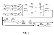
- FIG. 1 illustrates a transmitter and receiver structure arranged to implement multi-layered coded modulation in accordance with an embodiment of an aspect of the invention.
- FIG. 2 is a flowchart of a design procedure for the multi-layered coded modulation arrangement.
- FIG. 3 illustrates examples of different spatial interleaver designs.
- FIG. 1 illustrates a multiple-input multiple-output (MIMO) system suitable for practice of an embodiment of the present invention.
- MIMO multiple-input multiple-output
- the transmitter receives multiple data blocks for transmission.
- the information to be transmitted can either come in the form of multiple data blocks (e.g., progressive layered media data) or can be divided into multiple data blocks with appropriate lengths.
- the multiple data blocks are independently coded by binary random encoders 111 , 112 , . . . 115 with proper coding rates and preferably mapped to complex symbols at 121 , 122 , . . . 125 .
- the symbols from all the layers are then mapped to distinct transmission slots (e.g., space-time or space-frequency slots) in the order that is determined by spatial interleaver 140 , as further described herein.
- the symbols are then transmitted from multiple antennas 141 , 142 , . . . 145 in K symbol intervals (or K OFDM subcarriers).
- the following baseband discrete-time MIMO signal model can be used to describe the transmission:
- the above signal model can be rewritten as
- ⁇ k [i] denotes the N t i -size index set of sub-transmit antenna channel(s) use by the i-th layer transmission, which is one-to-one determined by ⁇ k and can be better understood through examples depicted in FIG. 3 and described in further detail herein;
- x k,i is
- the channel model can be used to represent narrow-band MIMO channels such that data ⁇ x k ⁇ are transmitted in time domain and channels ⁇ H k ⁇ in general are time-correlated due to Doppler fading as
- ⁇ H k ⁇ i , j ⁇ ⁇ n - ⁇ f ⁇ d ⁇ ⁇ f ⁇ d ⁇ ⁇ ⁇ i , j ⁇ [ n ] ⁇ ⁇ e j ⁇ ⁇ 2 ⁇ ⁇ ⁇ ⁇ ⁇ nk / K ( 2 )
- ⁇ H k ⁇ i,j denotes the (i,j)-th element of matrix H k
- the channel model can be
- a successive decoding structure can be employed at the receiver to recover the information data layer-by-layer, given the channel matrices Hk, ⁇ k and the SNR ⁇ .
- the transmitted signals are received by antennas 151 , 152 , . . . 155 and a spatial deinterleaver 150 is applied.
- the decoding then proceeds sequentially from layer- 1 (the first decoded layer) to layer- 2 (the second decoded layer) to layer-M (the last decoded layer) by applying demodulators 161 , 162 . . . 165 and decoders 171 , 172 . . . 175 to demodulate and decode layer- 1 , layer- 2 . . . layer-M. respectively.
- the receiver performs a linear MMSE demodulation by heating both un-decoded layers' signals and ambient noise as background noise, e.g., the i-th layer symbol vector is demodulated as
- the LMMSE I above denotes the traditional LMMSE filter that minimizes the mean-square error between X k,i and ⁇ circumflex over (x) ⁇ k,i .
- the LMMSE II above denotes the LMMSE filter specifically adapted herein which, compared to LMMSE I, does not include the term h k, ⁇ k [i] inside the inverted matrix.
- N t i 1
- LMMSE I and LMMSE II only differ by a positive multiplier (i.e., C k,i degen the same signal-to-interference-plus-noise-ratio (SINR) of the LMMSE output ⁇ circumflex over (x) ⁇ k,i .
- ⁇ circumflex over (x) ⁇ k,i can be written as
- the soft information (the likelihood ratio) of X k,i can be computed from equation 6.
- the channel decoder Based on the soft information of x k , the channel decoder performs decoding for layer-k. Next, layer-k's signals are reconstructed from the hard decoding output if decoding is successfUl (or from the soft decoding output if decoding has failed), and subtracted from the received signal to obtain y k,i+1 .
- a standard way of testing the integrity (and correctness) of the decoded data includes using a cyclic redundancy check, which implies a negligible loss of data rate.
- FIG. 1 when used in ergodic fading channels, is capable of achieving optimal performance when all M layers transmit with equal power and with coding rates computed as follows.
- the outage capacity is commonly used as a measure of performance limit.
- an LMMSE demodulator of a particular layer always treats the other undecoded layers signals as interference, and the information rate r i only affects the decoding performance but not the LMMSE demodulation performance.
- N t i 1, ⁇ i
- r ideal ⁇ k,i
- r ldpc ⁇
- P FER ( ⁇ , r ldpc ) ⁇ circumflex over (P) ⁇ e , ⁇ R + ⁇ (13)
- the FER performance is well represented by the outage probability of the fading channel when the block size is large.
- the function r ldpc ( ⁇ ) can be increased by properly optimizing the LDPC code design and construction in AWGN channels which leads to better performance in MIMO fading channels.
- spatial interleaving is unnecessary to achieve capacity in ergodic MIMO fading channels, spatial interleaving plays a more important role in non-ergodic MIMO fading channels.
- a spatial interleaving function (I) no spatial interleaving; (II) random (uniform) spatial interleaving; and (III) spatial ordering (assisted with a low-rate feedback channel).
- the disadvantages of a type-I design in non-ergodic channels is evident—the transmit-antenna diversity is not exploited for individual layers.
- the type-II design uniformly exploits the transmit antenna diversity for each layer. This goal can be achieved by the known D-BLAST structure as depicted in FIG. 3B .
- q i ⁇ ⁇ ⁇ ⁇ h i ⁇ F , which is adopted to indicate the sub-spatial channel quality, is computed at the receiver.
- the transmitter then transmits layer-i from the S i -th transmitter antenna ⁇ i, with the information rate r i .
- the rates ⁇ r i ⁇ are preferably determined off-line (by following a procedure similar to the one described below) based on the ensemble of the equivalently ranked channels ⁇ h S i ⁇ , rather than the instantaneous channel realizations.
- the type-II design reflects the idea of (passive) equal-gain transmission, while the type-III design practices the (proactive) selective transmission. Numerical experiments show that both type-II and type-III yield better performance than a type-I design in non-ergodic fading channels.
- Type-II provides relatively more consistent and superior performance in various channel profiles; a type-III design could be useful in support of higher information rate for layer- 1 transmission (the layer first decoded and faced with the strongest interference).
- FIG. 2 is a flowchart illustrating the optimization of the modulation design for non-ergodic fading channels, in accordance with an embodiment of an aspect of the invention.
- initialization is performed.
- ⁇ and ⁇ circumflex over (P) ⁇ e are set, as well as the statistical profiles (delay profile, Doppler spectrum) of the non-ergodic MIMO fading channels.
- the spatial interleaver
- the design outputs of MLC are coding rates and constellation partition of different levels, where the design outputs of the present approach are coding rates and transmission powers of different layers.
- MLC multilevel coded modulation
- MLC computes multi-stage decoding where individual level's decoding is conditioned on the decoding results of earlier-decoded levels, and the mutual information of each MLC level's equivalent channel is noise-limited, e.g., for a three-level 8-ASK MLC scheme, each level's mutual information goes to one (the maximum value for binary-input signaling of each MLC level) as SNR goes to infinity.
- the present invention utilizes successive cancellation decoding where an individual layer's decoding is independent of the decoding results of earlier-decoded layers (assuming that the decoded layers' signals are ideally cancelled out), and the mutual information of each layer's equivalent channel is interference-limited, e.g., for a two-layer example above, the SINR of the layer- 1 's equivalent channel converges to the signal-to-interference (SIR)
- SIR signal-to-interference
- Bit-interleaved coded modulation is so far the most widely-used coded modulation scheme in the large block size regime, because of its simple and robust design and capacity-approaching performance. It is worth noting that in single-antenna systems, turbo signal processing (i.e., the iteration between demodulator and decoder) is not needed and a conventional non-iterative receiver is enough to achieve optimum performance as long as Gray mapping is used. See G. Caire et al., “Bit-Interleaved Coded Modulation,” IEEE Trans. Inform. Theory, Vol. 44, pp. 927-46 (May 1998).
- turbo iterative processing is crucial to successively cancel out the spatial interference, even when an optimal APP demodulator is used.
- the present invention can also be used to carry out iterative successive-decoding, for better receiver performance in non-ergodic fading channels and for finite-length codes.
- the extra processing delay introduced in turbo signal processing is not always affordable, and it is accordingly advantageous herein to focus on low-processing-delay receiver designs.
- the non-iterative BICM-LMMSE i.e., BICM employing a LMMSE demodulator
- the above-disclosed receivers have roughly the same computational complexity and processing delay in transmitting the same total information rate and using the same modulation constellation, based on the observation that the complexity and the delay of both demodulation and decoding are approximately linear in block size. Furthermore, if the block size effect on decoding performance is ignored, the non-iterative BICM-LMMSE demodulator performance is the same as the layer- 1 demodulation performance in the present scheme, but the layer- 1 performance after decoding is better than that of BICM-LMMSE.
- the optimized scheme described above employs for its layer- 1 stronger error-correction coding than that for BICM-LMMSE, assuming both schemes have the same total information rate and the same constellation.
- the optimized modulation scheme herein disclosed can even outperform a non-iterative BICM-APP receiver. From simulation examples in realistic MIMO fading channels, the present invention with practical coded modulation (QPSK, block size 4096) can perform only 2.5 dB from the outage capacity in support of 3.0 bits/Hz/s rate transmission.
- QPSK coded modulation
Landscapes
- Engineering & Computer Science (AREA)
- Computer Networks & Wireless Communication (AREA)
- Signal Processing (AREA)
- Radio Transmission System (AREA)
Abstract
Description
where γ denotes the average transmission power from all transmit antennas (or equivalently the SNR); Nt (Nr) denotes the number of transmit (receive) antennas; yk∈CN
where hk,πdi k [i] denotes the Nr×Nt i spatial sub-channel matrix of the ith layer of the multi-lay coded modulation scheme which transmits from Nt i(Nt i≧1) transmit antennas, with Σi=1 M Nt i≡Nt; πk [i] denotes the Nt i-size index set of sub-transmit antenna channel(s) use by the i-th layer transmission, which is one-to-one determined by Πk and can be better understood through examples depicted in
where {Hk}i,j denotes the (i,j)-th element of matrix Hk; {circumflex over (f)}d
where αi,j[n], ∀n are independent circularly symmetric complex Gaussian random variables, with variances determined by the delay spread profile of the L-tap multipath fading channels and normalized as Σn Var{αi,j[n]}=1; it is assumed that αi,j are mutually independent for different (i,j)-antenna pairs.
where IN denotes the identity matrix of size N;
With the knowledge of the distribution of the equivalent noise, the soft information (the likelihood ratio) of Xk,i can be computed from
See M. K. Varanasi and T. Guess, “Optimum Decision Feedback Multiuser Equalization with Successive Decoding Achieves the Total Capacity of the Gaussian multiple-access channel,” in Asilomar Conference on Signals, Systems & Computers (November 1997). By enumerating H=Hk, k=1, . . . , K above and taking expectation with respect to H
where EH{f(H)} denotes the expectation of f(H) over H; EHCi(γ,H) is the average mutual information of the i-th layer of successive decoding; and and EHC(γ,H) is the ergodic capacity of this block fading MIMO channel. Note the following:
-
- The equality in equation 8 indicates that the disclosed modulation scheme is capable of achieving the capacity of ergodic MIMO fading channels under the assumption that Gaussian signaling is employed with coding rate ri=EHCi(γ,H) and successive LMMSE-based cancellation and decoding is performed at each layer. In particular, the equality holds true only when all M layers transmit with equal power, i.e., αi=1, ∀i.
- The ergodic-capacity-achieving property always holds, regardless of the specific values of (Nr, Nt, Nt i, ∀i). At the receiver side, the successive decoding at the i-th layer is concerned with an equivalent Nt i-input Nr-output vector channel (if Nt i>1). Hence, there exists a possible tradeoff between the decoding complexity reduction (M instead of Nt decoders, M<Nt) and the demodulation complexity increase (demodulator for vector-input instead of for scalar-input).
- The ergodic-capacity-achieving property of the modulation scheme hinges on the fact that each layer experiences ergodic fading channels with infinite diversity order. In particular, there is no loss of optimality if each layer transmits only from fixed transmit antenna(s) and thus without explicitly exploiting transmit-antenna diversity.
- In practice, the ergodic MIMO fading channel capacity can be approached (by a fraction of dB) by coded modulation schemes based on binary random codes (e.g., turbo codes or LDPC codes) with very large block size and by successive LMMSE cancellation and decoding (as discussed above). Note that the coded modulation design motivated by the equation above does not follow the conventional design path started from pairwise error probability (PEP) of the decoder, but, nonetheless, leads to pragmatically good performance in MIMO systems.
It can be then shown that the optimal solutions to the above optimization problem, when existing for given γ, are {ri*}i=1 M satisfying
P out 1(γ,r 1*)≡P out 2(γ,r 2*)≡ . . . ≡P out M(γ, r M*)≡{circumflex over (P)} e (10)
where the superscript * denotes the optimal value of individual variables. Note that the parameters that are explicitly optimized above are the information rates ri of all layers (achieved jointly by binary coding and MPSK or MQAM constellation; it is possible to have ri≧1); in fact, the optimal solutions also implicitly depend on space-time (or space-frequency) channel interleaving functions, as discussed below. It should be further remarked that the solution to the above equation only achieves the equal error protection at a particular SNR (such as to satisfy the given target error rate {circumflex over (P)}e), instead of all SNRs.
Using a Gaussian approximation of the output of the LMMSE filter, the instantaneous mutual information of the i-th layer in equation 8 can be re-written as
In practice, given the same (γ, H), the information rate supported by practical coded modulation is always strictly less than rideal(ξk,i).
r ldpc(ξ)={r ldPC ∈R + |P FER(ξ, r ldpc)={circumflex over (P)} e ,ξ∈R +} (13)
Note that the FER performance is well represented by the outage probability of the fading channel when the block size is large. The function rldpc(ξ) can be increased by properly optimizing the LDPC code design and construction in AWGN channels which leads to better performance in MIMO fading channels. A rate function of practical coded modulation, e.g., rldpc(ξ) of the ensembles of practical LDPC codes, can be generated as follows: (1) construct LDPC codes with a given code block length and with various coding rates (e.g., {circumflex over (r)}=0.1k, k=1, . . . , 9) from LDPC code ensembles; (2) run Monte Carlo simulations of the LDPC decoding in discrete-input-continuous-output AWGN channels, where LDPC code bits are modulated into discrete constellation with Gray mapping; (3) read the minimum SNR {circumflex over (ξ)} required to achieve a target FER (e.g., 5e-3) from the FER-vs-SNR plots for various rates; (4) by polynomial interpolation of all pairs of {circumflex over (r)} and {circumflex over (ξ)}, rldpc(ξ) can be obtained.
It can be shown that any realization of a type-II spatial interleaver shares the property that
meaning that the i-th layer employs each transmit antenna evenly. Illustrative examples of a type-II random spatial interleaver design and the D-BLAST design are shown in
which is adopted to indicate the sub-spatial channel quality, is computed at the receiver. Second, by ranking all qi's at the receiver, the resultant index set {Si}i=1 M={Si∈Z+, 1≦Si≦M|qs
is also set. Then, Monte Carlo sampling is performed at
for example, by using
from the Monte Carlo samples. Then, at
Claims (20)
Priority Applications (1)
| Application Number | Priority Date | Filing Date | Title |
|---|---|---|---|
| US11/259,323 US7539261B2 (en) | 2005-08-22 | 2005-10-26 | Multi-layer coded modulation for non-ergodic block fading channels |
Applications Claiming Priority (2)
| Application Number | Priority Date | Filing Date | Title |
|---|---|---|---|
| US71009505P | 2005-08-22 | 2005-08-22 | |
| US11/259,323 US7539261B2 (en) | 2005-08-22 | 2005-10-26 | Multi-layer coded modulation for non-ergodic block fading channels |
Publications (2)
| Publication Number | Publication Date |
|---|---|
| US20070041461A1 US20070041461A1 (en) | 2007-02-22 |
| US7539261B2 true US7539261B2 (en) | 2009-05-26 |
Family
ID=37767299
Family Applications (1)
| Application Number | Title | Priority Date | Filing Date |
|---|---|---|---|
| US11/259,323 Expired - Fee Related US7539261B2 (en) | 2005-08-22 | 2005-10-26 | Multi-layer coded modulation for non-ergodic block fading channels |
Country Status (1)
| Country | Link |
|---|---|
| US (1) | US7539261B2 (en) |
Cited By (5)
| Publication number | Priority date | Publication date | Assignee | Title |
|---|---|---|---|---|
| US10848990B2 (en) | 2007-06-05 | 2020-11-24 | Constellation Designs, LLC | Transmitters incorporating uniform and non-uniform constellations with rings |
| US11018922B2 (en) | 2007-06-05 | 2021-05-25 | Constellation Designs, LLC | Methods and apparatuses for signaling with geometric constellations |
| US11039324B2 (en) | 2007-06-05 | 2021-06-15 | Constellation Designs, LLC | Methods and apparatuses for signaling with geometric constellations in a Rayleigh fading channel |
| US12289192B2 (en) | 2008-12-30 | 2025-04-29 | Constellation Designs, LLC | Systems and methods for receiving data transmitted using non-uniform QAM 256 constellations |
| US12425885B2 (en) | 2010-07-08 | 2025-09-23 | Constellation Designs, LLC | Systems and methods for receiving data transmitted using non-uniform QAM 256 constellations via fading channels |
Families Citing this family (15)
| Publication number | Priority date | Publication date | Assignee | Title |
|---|---|---|---|---|
| KR100849328B1 (en) * | 2005-11-22 | 2008-07-29 | 삼성전자주식회사 | Apparatus and method for determining transmit/receive antenna in a communication system using multi antenna |
| US8363738B2 (en) * | 2005-12-05 | 2013-01-29 | Qualcomm Incorporated | Hierarchical coding for multicast messages |
| US8102923B2 (en) | 2005-12-05 | 2012-01-24 | Qualcomm Incorporated | Hierarchical coding for multicast messages |
| US8340006B2 (en) * | 2006-04-12 | 2012-12-25 | Panasonic Corporation | Transmission of multicast/broadcast services in a wireless communication network |
| US7944985B2 (en) * | 2006-08-24 | 2011-05-17 | Interdigital Technology Corporation | MIMO transmitter and receiver for supporting downlink communication of single channel codewords |
| EP2103025B1 (en) | 2006-12-14 | 2013-03-27 | Thomson Licensing | Arq with adaptive modulation for communication systems |
| JP5297387B2 (en) | 2006-12-14 | 2013-09-25 | トムソン ライセンシング | Rateless encoding in communication systems |
| EP2103023B1 (en) | 2006-12-14 | 2015-04-15 | Thomson Licensing | Rateless codes decoding method for communication systems |
| US20090304117A1 (en) * | 2006-12-14 | 2009-12-10 | Joshua Lawrence Koslov | Concatenated coding/decoding in communication systems |
| EP2552043A1 (en) * | 2011-07-25 | 2013-01-30 | Panasonic Corporation | Spatial multiplexing for bit-interleaved coding and modulation with quasi-cyclic LDPC codes |
| US8885276B2 (en) * | 2013-02-14 | 2014-11-11 | Lsi Corporation | Systems and methods for shared layer data decoding |
| EP3231145B1 (en) | 2014-12-12 | 2021-07-07 | Sony Corporation | Transmitter and receiver using channel bundling |
| CN106788626B (en) * | 2016-12-02 | 2020-05-19 | 西安交通大学 | An Improved Orthogonal Spatial Modulation Transmission Method That Can Obtain Second-Order Transmit Diversity |
| US20210379701A1 (en) * | 2020-06-08 | 2021-12-09 | Standex International Corporation | Laser engraving using stochastically generated laser pulse locations |
| CN116506074B (en) * | 2023-06-27 | 2023-09-05 | 华侨大学 | Combined source channel coding method and system based on block fading channel |
Citations (2)
| Publication number | Priority date | Publication date | Assignee | Title |
|---|---|---|---|---|
| US20050220211A1 (en) * | 2004-04-02 | 2005-10-06 | Lg Electronics Inc. | Signal processing apparatus and method in multi-input/multi-output communications systems |
| US20060233280A1 (en) * | 2005-04-19 | 2006-10-19 | Telefonaktiebolaget L M Ericsson | Selection of channel coding and multidimensional interleaving schemes for improved performance |
Family Cites Families (4)
| Publication number | Priority date | Publication date | Assignee | Title |
|---|---|---|---|---|
| US3903297A (en) * | 1973-11-01 | 1975-09-02 | Upjohn Co | Method of treatment and prophylaxis of gastric hypersecretion and gastric and duodenal ulcers using prostaglandin analogs |
| US6251938B1 (en) * | 1996-12-18 | 2001-06-26 | Teva Pharmaceutical Industries, Ltd., | Phenylethylamine derivatives |
| PT966435E (en) * | 1996-12-18 | 2005-06-30 | Yissum Res Dev Co | AMINOINDAN DERIVATIVES |
| US20040010038A1 (en) * | 2002-02-27 | 2004-01-15 | Eran Blaugrund | Propargylamino indan derivatives and propargylamino tetralin derivatives as brain-selective MAO inhibitors |
-
2005
- 2005-10-26 US US11/259,323 patent/US7539261B2/en not_active Expired - Fee Related
Patent Citations (2)
| Publication number | Priority date | Publication date | Assignee | Title |
|---|---|---|---|---|
| US20050220211A1 (en) * | 2004-04-02 | 2005-10-06 | Lg Electronics Inc. | Signal processing apparatus and method in multi-input/multi-output communications systems |
| US20060233280A1 (en) * | 2005-04-19 | 2006-10-19 | Telefonaktiebolaget L M Ericsson | Selection of channel coding and multidimensional interleaving schemes for improved performance |
Cited By (26)
| Publication number | Priority date | Publication date | Assignee | Title |
|---|---|---|---|---|
| US11889326B2 (en) | 2007-06-05 | 2024-01-30 | Constellation Designs, LLC | Methods of receiving data transmitted using unequally spaced constellations that provide reduced SNR requirements as compared to equally spaced constellations |
| US12010531B2 (en) | 2007-06-05 | 2024-06-11 | Constellation Designs, LLC | Methods of transmitting data using non-uniform constellations with overlapping constellation point locations |
| US10863370B2 (en) | 2007-06-05 | 2020-12-08 | Constellation Designs, LLC | Transmitters incorporating uniform and non-uniform constellations and adaptive selection |
| US10887780B2 (en) | 2007-06-05 | 2021-01-05 | Constellation Designs, LLC | Receivers incorporating uniform and non-uniform constellations and adaptive selection |
| US11018922B2 (en) | 2007-06-05 | 2021-05-25 | Constellation Designs, LLC | Methods and apparatuses for signaling with geometric constellations |
| US11019509B2 (en) | 2007-06-05 | 2021-05-25 | Constellation Designs, LLC | Receivers incorporating non-uniform constellations with overlapping constellation point locations |
| US11039324B2 (en) | 2007-06-05 | 2021-06-15 | Constellation Designs, LLC | Methods and apparatuses for signaling with geometric constellations in a Rayleigh fading channel |
| US11051187B2 (en) | 2007-06-05 | 2021-06-29 | Constellation Designs, LLC | Transmitters incorporating non-uniform constellations with overlapping constellation point locations |
| US11864006B2 (en) | 2007-06-05 | 2024-01-02 | Constellation Designs, LLC | Methods of transmitting data using uniform and non-uniform constellations with rings |
| US11864007B2 (en) | 2007-06-05 | 2024-01-02 | Constellation Designs, LLC | Communication systems capable of receiving and processing data using unequally spaced and uniform quadrature amplitude modulated 64 point symbol constellations |
| US11871252B2 (en) | 2007-06-05 | 2024-01-09 | Constellation Designs, LLC | Methods of receiving data using unequally spaced quadrature amplitude modulated 64 point symbol constellations |
| US11877164B2 (en) | 2007-06-05 | 2024-01-16 | Constellation Designs, LLC | Methods of receiving data using unequally spaced and uniform quadrature amplitude modulated 64 point symbol constellations |
| US10848989B2 (en) | 2007-06-05 | 2020-11-24 | Constellation Designs, LLC | Receivers incorporating uniform and non-uniform constellations with rings |
| US12556946B2 (en) | 2007-06-05 | 2026-02-17 | Constellation Designs, LLC | Methods of receiving data transmitted using non-uniform multidimensional constellation and code rate pairs |
| US11991535B2 (en) | 2007-06-05 | 2024-05-21 | Constellation Designs, LLC | Methods of communicating data transmitted using non-uniform multidimensional constellation and code rate pairs |
| US11930379B2 (en) | 2007-06-05 | 2024-03-12 | Constellation Designs, LLC | Methods of receiving data using uniform and non-uniform constellations with rings |
| US11963019B2 (en) | 2007-06-05 | 2024-04-16 | Constellation Designs, LLC | Methods of receiving data transmitted using non-uniform constellations with overlapping constellation point locations |
| US11974145B2 (en) | 2007-06-05 | 2024-04-30 | Constellation Designs, LLC | Methods of transmitting data using non-uniform multidimensional constellation and code rate pairs |
| US11902078B2 (en) | 2007-06-05 | 2024-02-13 | Constellation Designs, LLC | Methods and apparatuses for signaling with geometric constellations |
| US10848990B2 (en) | 2007-06-05 | 2020-11-24 | Constellation Designs, LLC | Transmitters incorporating uniform and non-uniform constellations with rings |
| US12035151B2 (en) | 2007-06-05 | 2024-07-09 | Constellation Designs, LLC | Methods of receiving data transmitted using non-uniform multidimensional constellation and code rate pairs |
| US12041468B2 (en) | 2007-06-05 | 2024-07-16 | Constellation Designs, LLC | Methods and apparatuses for signaling with geometric constellations in a Rayleigh fading channel |
| US11895513B2 (en) | 2007-06-05 | 2024-02-06 | Constellation Designs, LLC | Methods of transmitting data using unequally spaced constellations that provide reduced SNR requirements as compared to equally spaced constellations |
| US12476859B2 (en) | 2007-06-05 | 2025-11-18 | Constellation Designs, LLC | Methods and apparatuses for signaling with geometric constellations |
| US12289192B2 (en) | 2008-12-30 | 2025-04-29 | Constellation Designs, LLC | Systems and methods for receiving data transmitted using non-uniform QAM 256 constellations |
| US12425885B2 (en) | 2010-07-08 | 2025-09-23 | Constellation Designs, LLC | Systems and methods for receiving data transmitted using non-uniform QAM 256 constellations via fading channels |
Also Published As
| Publication number | Publication date |
|---|---|
| US20070041461A1 (en) | 2007-02-22 |
Similar Documents
| Publication | Publication Date | Title |
|---|---|---|
| US7539261B2 (en) | Multi-layer coded modulation for non-ergodic block fading channels | |
| US7508748B2 (en) | Rate selection for a multi-carrier MIMO system | |
| CN101507167B (en) | MIMO transmitter and receiver for supporting downlink communication of single channel codewords | |
| US8472565B2 (en) | Apparatus for processing received signal, method thereof, and method for selecting mapping rule | |
| Lu et al. | Performance analysis and design optimization of LDPC-coded MIMO OFDM systems | |
| US7359313B2 (en) | Space-time bit-interleaved coded modulation for wideband transmission | |
| RU2317648C2 (en) | Method for processing signals with decomposition onto native channel modes and with inversion of channel for 3g network based systems | |
| US8451951B2 (en) | Channel classification and rate adaptation for SU-MIMO systems | |
| CN1639996B (en) | Data transmission with non-uniform distribution of data rates for a multiple-input multiple-output (MIMO) system | |
| US8867662B2 (en) | Multidimensional constellations for coded transmission | |
| TWI392259B (en) | Spatially extended broadcast transmission in a multi-antenna communication system | |
| US6898248B1 (en) | System employing threaded space-time architecture for transporting symbols and receivers for multi-user detection and decoding of symbols | |
| US8175181B1 (en) | Method and apparatus for selecting a modulation coding scheme | |
| EP2391020B1 (en) | Method and device for efficient multi-user multi-variant parallel transmission | |
| US20070258536A1 (en) | Method and system for reordered QRV-LST (layered space time) detection for efficient processing for multiple input multiple output (MIMO) communication systems | |
| EP1705822A2 (en) | Method and apparatus for detecting and decoding a signal in a MIMO communication system | |
| Jang et al. | On the combining schemes for MIMO systems with hybrid ARQ | |
| CN101166047A (en) | Transmitting device, receiving device, transmitting method and receiving method of multi-antenna communication system utilizing channel geometric mean decomposition | |
| US8139668B2 (en) | Unified STTC encoder for WAVE transceivers | |
| CN108833325B (en) | Novel MIMO-OFDM system grouping adaptive modulation method | |
| Michalke et al. | Linear MIMO receivers vs. tree search detection: A performance comparison overview | |
| Kumar et al. | Performance analysis of PAPR reduction in STBC MIMO-OFDM system | |
| Lu et al. | A space-time trellis code design method for OFDM systems | |
| Lu et al. | Design of multilayer coded modulation for nonergodic block-fading channels | |
| Lee et al. | Transceiver design based on blockwise uniform channel decomposition for coded MIMO systems |
Legal Events
| Date | Code | Title | Description |
|---|---|---|---|
| AS | Assignment |
Owner name: NEC LABORATORIES AMERICA, INC., NEW JERSEY Free format text: ASSIGNMENT OF ASSIGNORS INTEREST;ASSIGNORS:LU, BEN;WANG, XIAODONG;MADIHIAN, MOHAMMAD;REEL/FRAME:016853/0306 Effective date: 20051130 |
|
| STCF | Information on status: patent grant |
Free format text: PATENTED CASE |
|
| AS | Assignment |
Owner name: NEC CORPORATION,JAPAN Free format text: ASSIGNMENT OF ASSIGNORS INTEREST;ASSIGNOR:NEC LABORATORIES AMERICA, INC.;REEL/FRAME:023957/0816 Effective date: 20100216 Owner name: NEC CORPORATION, JAPAN Free format text: ASSIGNMENT OF ASSIGNORS INTEREST;ASSIGNOR:NEC LABORATORIES AMERICA, INC.;REEL/FRAME:023957/0816 Effective date: 20100216 |
|
| FPAY | Fee payment |
Year of fee payment: 4 |
|
| FPAY | Fee payment |
Year of fee payment: 8 |
|
| FEPP | Fee payment procedure |
Free format text: MAINTENANCE FEE REMINDER MAILED (ORIGINAL EVENT CODE: REM.); ENTITY STATUS OF PATENT OWNER: LARGE ENTITY |
|
| LAPS | Lapse for failure to pay maintenance fees |
Free format text: PATENT EXPIRED FOR FAILURE TO PAY MAINTENANCE FEES (ORIGINAL EVENT CODE: EXP.); ENTITY STATUS OF PATENT OWNER: LARGE ENTITY |
|
| STCH | Information on status: patent discontinuation |
Free format text: PATENT EXPIRED DUE TO NONPAYMENT OF MAINTENANCE FEES UNDER 37 CFR 1.362 |
|
| FP | Lapsed due to failure to pay maintenance fee |
Effective date: 20210526 |