EP2029919B1 - Gleitring einer gleitringdichtungsanordnung - Google Patents
Gleitring einer gleitringdichtungsanordnung Download PDFInfo
- Publication number
- EP2029919B1 EP2029919B1 EP07764624A EP07764624A EP2029919B1 EP 2029919 B1 EP2029919 B1 EP 2029919B1 EP 07764624 A EP07764624 A EP 07764624A EP 07764624 A EP07764624 A EP 07764624A EP 2029919 B1 EP2029919 B1 EP 2029919B1
- Authority
- EP
- European Patent Office
- Prior art keywords
- diamond
- base body
- layer
- diamond layer
- seal ring
- Prior art date
- Legal status (The legal status is an assumption and is not a legal conclusion. Google has not performed a legal analysis and makes no representation as to the accuracy of the status listed.)
- Active
Links
Images
Classifications
-
- F—MECHANICAL ENGINEERING; LIGHTING; HEATING; WEAPONS; BLASTING
- F16—ENGINEERING ELEMENTS AND UNITS; GENERAL MEASURES FOR PRODUCING AND MAINTAINING EFFECTIVE FUNCTIONING OF MACHINES OR INSTALLATIONS; THERMAL INSULATION IN GENERAL
- F16J—PISTONS; CYLINDERS; SEALINGS
- F16J15/00—Sealings
- F16J15/16—Sealings between relatively-moving surfaces
- F16J15/34—Sealings between relatively-moving surfaces with slip-ring pressed against a more or less radial face on one member
- F16J15/3496—Sealings between relatively-moving surfaces with slip-ring pressed against a more or less radial face on one member use of special materials
Definitions
- the invention relates to a sliding ring of a mechanical seal assembly.
- the invention relates to a sliding ring with a base body made of a carbide material, wherein on one of the end faces of the base body a wear-resistant layer of a diamond material is provided, which provides a sliding surface.
- carbide materials such as WC or SiC
- WC or SiC which are preferred in slip rings due to their special mechanical properties and temperature resistance in certain applications, such as in the chemical industry, in the presence of aggressive media, such as acids, alkalis, or in electro- chemical attack tend to lose their inner structural cohesion or to corrode out of unresolved circumstances. Measures to prevent the corrosion of such slip rings are not known, despite the great need for a solution to this problem. However, in slip rings, measures to dissipate electrical charges are known to provide spark erosion.
- the invention has for its object to provide a comprehensive usable seal ring of the type mentioned with a body of carbide material with significantly increased life.
- the inventive coating of at least the surface of the slip rings of a mechanical seal assembly exposed to medium to be sealed during operation permits the use of the advantageous properties of carbide materials such as WC or SiC in the presence of aggressive media leading to corrosion by providing them with a diamond material grown in situ on the surfaces are prevented from contacting the carbide material by the diamond coating.
- slip rings can be provided with practically only by wear on the sliding surfaces limited life for use with almost all media to be sealed at a very large range of pressures and temperatures.
- the diamond layer may be electrically conductive at least at the areas of the base body which do not coincide with the sliding surface. This allows the dissipation of electrostatic charges and prevents possible spark erosion.
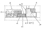
- the drawing shows in fragmentary, longitudinal sectional view of a mechanical seal assembly with a pair of trained according to the invention slip rings.
- a mechanical seal assembly with a pair of cooperating seal rings 1, 2, one of which (1) against a stationary part, such as a pump housing, and the other (2) for common rotation with a shaft (not shown), eg a Pumpenlaufradwelle connected.
- a shaft not shown
- the device 4 is used for torque-transmitting connection of the sliding ring 2 with the shaft, and comprises a biasing spring 5 for axial loading of the sliding ring 2 with a biasing force, so that it is pressed against the stationary seal ring 1 to the facing sliding surfaces 6, 7 of the slip rings 1, 2 to keep in sealing engagement with each other.
- the sliding surfaces 6, 7 of the sliding rings 1, 2 are located on the outer smooth surfaces of diamond layers 8, 9, which are formed in a conventional manner at the mutually facing end faces of the seal rings 1, 2.
- Each slip ring 1, 2 has an annular base body 10, 11 with a suitable cross-sectional configuration of a carbide material such as tungsten carbide (WC) or silicon carbide (SiC). These materials are preferred for sliding rings because of their high thermal and mechanical strength in applications with special requirements.
- a carbide material such as tungsten carbide (WC) or silicon carbide (SiC).
- a diamond coating not only the mutually facing end faces of the seal rings 1, 2 a diamond coating, but is in the illustrated embodiment of the invention, the entire surface of the base body 10, 11 of each slide ring 1, 2 of a diamond layer 12, 13 hermetically sealed, so that the material of the base body 10, 11 is completely covered by the diamond layers 8, 12 and 9, 13, respectively.
- a diamond coating could be deposited only on those surface areas exposed to the attack of a corrosive medium during operation.
- While a main requirement for the sliding-surface-side diamond layers 8, 9 is good tribological property, in particular good surface quality and high wear resistance with simultaneous medium-tightness, the medium-tightness of the remaining surface regions of the base body 10, 11 covering diamond layers 12, 13 in the foreground, while lower demands are made on the surface finish of the diamond layers 12, 13 and quality of the diamond structure.
- Medium-density diamond layers with the desired specifications can be formed by single-layer or multi-layered in situ growth on the base bodies 10, 11 by the CVD method, in particular hot-filament CVD methods. This technology is known in the art and therefore needs no further explanation.
- the thickness of the diamond layers 8, 9 and 12, 13 should be between about 0.05 and 15 microns.
- the individual diamond layers 8, 9 and 12, 13 have different thicknesses.
- the thickness of the diamond layers 8, 9 or 12, 13 to be selected is i.a. determined by the type of medium to be sealed. In the case of particularly aggressive media such as HF acid, only occasionally occurring micropores must be prevented and therefore a high layer thickness should be provided, while in other media such as sulfuric acid, hydrochloric acid, sodium hydroxide often a layer thickness between 3.0 and 4.0 microns is sufficient.
- At least the diamond layers 12, 13, preferably also the sliding surface-side diamond layers 8, 9, are designed to be electrically conductive.
- electrically conductive impurities such as boron can be introduced into the starting material for the diamond growth, as is known from the production of diamond electrodes.
Landscapes
- Engineering & Computer Science (AREA)
- General Engineering & Computer Science (AREA)
- Mechanical Engineering (AREA)
- Mechanical Sealing (AREA)
- Chemical Vapour Deposition (AREA)
Description
- Die Erfindung betrifft einen Gleitring einer Gleitringdichtungsanordnung. Die Erfindung betrifft insbesondere einen Gleitring mit einem Basiskörper aus einem karbidischen Material, wobei auf einer der Stirnflächen des Basiskörpers eine verschleissfeste Schicht aus einem Diamantmaterial ausgebildet ist, die eine Gleitfläche vorsieht.
- Es ist bekannt, Gleitringe und andere bei Betrieb Verschleiss ausgesetzte Bauteile mit lokalen, sehr glatten Diamantbeschichtungen zu versehen
EP0675303 A1 ,EP 0351554 A1 ,DE 19922665 A ,EP 0614999 A ), um an den tribologisch beanspruchten Stellen eine erhöhte Verschleissfestigkeit zu erhalten. In derDE 19922665 sind ferner mit weiteren Literaturhinweisen die technologischen Grundlagen zur In-situ-Herstellung ein- oder mehrlagiger Diamantbeschichtungen nach dem sog. Hot Filament CVD Verfahren (chemisches Abscheidungsverfahren mit Glühdraht) beschrieben. - Die Praxis hat gezeigt, dass karbidische Materialien, wie WC oder SiC, die bei Gleitringen aufgrund ihrer besonderen mechanischen Eigenschaften und Temperaturbeständigkeit bei bestimmten Anwendungsgebieten z.B. in der chemischen Industrie, bevorzugt werden, in Gegenwart aggressiver Medien, wie Säuren, Laugen, oder bei elektro-chemischem Angriff dazu neigen, aus noch nicht geklärten Umständen ihren inneren Gefügezusammenhalt zu verlieren bzw. zu korrodieren. Massnahmen, mit denen sich die Korrosion derartiger Gleitringe verhindern liesse, sind trotz hohem Bedarf nach einer Lösung dieses Problems, nicht bekannt geworden. Bekannt sind jedoch bei Gleitringen, Massnahmen zur Ableitung elektrischer Ladungen, die Funkenerosion vorzusehen.
- Der Erfindung liegt die Aufgabe zugrunde, einen umfassend einsetzbaren Gleitring der eingangs erwähnten Art mit einem Grundkörper aus karbidischem Material mit wesentlich erhöhter Lebensdauer zu schaffen.
- Diese Aufgabe wird erfindungsgemäss durch die Merkmale des Anspruches 1 gelöst.
- Die erfindungsgemässe Beschichtung wenigstens der bei Betrieb einem abzudichtenden Medium ausgesetzten Oberflächen der Gleitringe einer Gleitringdichtungsanordnung mit einem, vorzugsweise in situ auf den Oberflächen gewachsenen Diamantmaterial ermöglicht die Nutzung der vorteilhaften Eigenschaften karbidischer Materialien wie WC oder SiC in Gegenwart aggressiver, zu Korrosion führender Medien, indem diese durch die Diamantbeschichtung an einem Kontakt mit dem karbidischen Material gehindert sind. Dadurch lassen sich Gleitringe mit praktisch nur durch Verschleiss an den Gleitflächen begrenzter Lebensdauer zum Einsatz mit nahezu allen abzudichtenden Medien bei einer sehr grossen Spannweite von Drücken und Temperaturen bereitstellen.
- Gemäss einer vorteilhaften Weiterbildung der Erfindung kann die Diamantschicht wenigstens an den Bereichen des Basiskörpers, die nicht mit der Gleitfläche übereinstimmen, elektrisch leitend ist. Dies ermöglicht die Ableitung elektrostatischer Aufladungen und verhindert eventuelle Funkenerosion.
- Die Erfindung wird nachfolgend anhand einer Ausführungsform und der Zeichnung näher erläutert. Die Zeichnung zeigt in fragmentarischer, längsgeschnittener Ansicht eine Gleitringdichtungsanordnung mit einem Paar erfindungsgemäss ausgebildeter Gleitringe.
- In der Zeichnung dargestellt ist eine Gleitringdichtungsanordnung mit einem Paar zusammenwirkender Gleitringe 1, 2, von denen einer (1) drehfest gegenüber einem stationären Teil, z.B. einem Pumpengehäuse, und der andere (2) zur gemeinsamen Drehung mit einer Welle (nicht gezeigt), z.B. einer Pumpenlaufradwelle, verbunden ist. An einer allgemein mit 4 angedeuteten Einrichtung ist der Gleitring 2, vorzugsweise durch Presssitz, gehalten. Die Einrichtung 4 dient zur drehmomentübertragenden Verbindung des Gleitringes 2 mit der Welle, und umfasst eine Vorspannfeder 5 zur axialen Beaufschlagung des Gleitringes 2 mit einer Vorspannkraft, so dass dieser gegen den stationären Gleitring 1 gedrückt wird, um die einander zugewandten Gleitflächen 6, 7 der Gleitringe 1, 2 in dichtendem Eingriff miteinander zu halten.
- Die Gleitflächen 6, 7 der Gleitringe 1, 2, befinden sich an den äusseren glatten Oberflächen von Diamantschichten 8, 9, die in an sich bekannter Weise an den einander zugewandten Stirnflächen der Gleitringe 1, 2 ausgebildet sind.
- Jeder Gleitring 1, 2 hat einen ringförmigen Basiskörper 10, 11 mit einer geeigneten Querschnittskonfiguration aus einem karbidischen Material wie Wolframkarbid (WC) oder Siliciumkarbid (SiC). Diese Materialien werden bei Gleitringen wegen ihrer hohen thermischen und mechanischen Belastbarkeit bei Anwendungen mit besonderen Anforderungen bevorzugt.
- Erfindungsgemäss weisen nicht nur die einander zugewandten Stirnflächen der Gleitringe 1, 2 eine Diamantbeschichtung auf, sondern ist bei der gezeigten Ausführungsform der Erfindung die gesamte Oberfläche des Basiskörpers 10, 11 jedes Gleit ringes 1, 2 von einer Diamantschicht 12, 13 hermetisch dicht umhüllt, so dass das Material des Basiskörpers 10, 11 vollständig von den Diamantschichten 8, 12 bzw. 9, 13 bedeckt ist. Wenn erwünscht, könnte eine Diamantbeschichtung nur auf solchen Oberflächenbereichen aufgegeben sein, die bei Betrieb dem Angriff eines korrosiven Medium ausgesetzt sind.
- Während eine Hauptanforderung an die gleitflächenseitigen Diamantschichten 8, 9 gute tribologische Eigenschaft, insbesondere gute Oberflächengüte und hohe Verschleissfestigkeit bei gleichzeitiger Mediumdichtigkeit ist, steht die Mediumdichtigkeit bei den die restlichen Oberflächenbereiche der Basiskörper 10, 11 abdeckenden Diamantschichten 12, 13 im Vordergrund, während an die Oberflächenbeschaffenheit der Diamantschichten 12, 13 und Güte des Diamantgefüges geringere Anforderungen gestellt werden.
- Mediumdichte Diamantschichten mit den gewünschten Spezifikationen können durch ein- oder mehrlagiges In-situ-Wachstum auf den Basiskörpern 10, 11 nach dem CVD-Verfahren, insbesondere Hot-Filament-CVD-Verfahren gebildet werden. Diese Technologie ist dem Fachmann bekannt und bedarf deshalb keiner näheren Erläuterung.
- Es wurde festgestellt, dass eine ausreichende Mediumdichtigkeit eine bestimmte Mindestdicke der Diamantschichten 8, 9 bzw. 12, 13 erforderlich macht. Versuche haben gezeigt, dass die Dicke der Diamantschichten 8, 9 bzw. 12, 13 zwischen etwa 0,05 und 15 µm betragen sollte. Die einzelnen Diamantschichten 8, 9 und 12, 13 naben unterschiedliche Dicken . Die zu wählende Dicke der Diamantschichten 8, 9 bzw. 12, 13 wird u.a. von der Art des abzudichtenden Mediums bestimmt. Bei besonders aggressiven Medien wie HF-Säure müssen auch nur vereinzelt auftretende Mikroporen verhindert und sollte daher eine hohe Schichtdicke vorgesehen werden, während bei anderen Medien wie Schwefelsäure, Salzsäure, Natronlauge häufig eine Schichtdicke zwischen 3,0 und 4,0 µm ausreichend ist.
- Zur Ableitung eventuell bei Betrieb auftretender elektrischer Aufladungen der Gleitringe 1, 2 kann ferner vorgesehen werden, dass wenigstens die Diamantschichten 12, 13, vorzugsweise auch die gleitflächenseitigen Diamantschichten 8, 9 elektrisch leitend beschaffen sind. Dazu können in das Ausgangsmaterial für das Diamantwachstum elektrisch leitende Verunreinigungen wie Bor eingegeben werden, wie dies aus der Herstellung von Diamantelektroden bekannt ist. Zu weiteren Details kann z.B. verwiesen werden auf M. Fryda, Th. Mathee, et al, "Fabrication and Application of Diacem Etektrodes", Diamond and Related Materials 12, 2003, S. 1950-1956.
- Die Erfindung wurde vorausgehend anhand einer Ausführungsform eine Gleitringdichtungsanordnung beschrieben, bei der beide Gleitringe aus karbischem Material bestehen und Diamantbeschichtungen aufweisen. Wenn erwünscht, könnte auch nur einer der zusammenwirkenden Gleitringe in der geschilderten Weise ausgebildet sein, während der andere aus einem nicht-karbidischen Material mit natürlicher Beständigkeit gegenüber den zum Einsatz kommenden Medien bestehen könnte.
Claims (6)
- Gleitring einer Gleitringdichtungsanordnung, mit einem Basiskörper (10,11) aus einem karbidischen Material, wobei auf einer der Stirnflächen des Basiskörpers eine verschleissfeste Schicht (8,9) aus einem Diamantmaterial ausgebildet ist, die eine Gleitfläche (6,7) vorsieht, dadurch gekennzeichnet, dass der Basiskörper (10,11) wenigstens an seinen bei Betrieb einem abzudichtenden Medium ausgesetzten Oberflächenbereichen in einer Schicht (8,9,12,13) aus Diamantmaterial mit einer Fluiddichtigkeit schaffende Schichtdicke und/oder Konfiguration hermetisch eingeschlossen ist, wobei eine Eigenschaft der Diamantschicht und/oder das Diamantmaterial an den Bereichen des Basiskörpers, die nicht mit der Gleitfläche (6,7) übereinstimmen, unterschiedlich zur gleitflächenseitigen Diamantschicht (8,9) ist, und wobei die Diamantschicht (8,9) an der Gleitfläche (6, 7) eine unterschiedliche Dicke zur Diamantschicht (12,13) an den beim Betrieb dem abzudichtenden Medium ausgesetzten Oberflächenbereichen aufweist.
- Gleitring nach Anspruch 1, dadurch gekennzeichnet, dass die Diamantschicht (8,9,12,13) wenigstens an den Bereichen des Basiskörpers (10.11), die nicht mit der Gleitfläche (6,7) übereinstimmen, elektrisch leitend ist.
- Gleitring nach Anspruch 1 oder 2, dadurch gekennzeichnet, dass jede Diamantschicht (8,9,12,13) eine Dicke zwischen etwa 0,05 und 15 µm hat, wobei die Schichtdicke umfänglich des Querschnitts des Basiskörpers (10,11) veränderlich ist.
- Gleitring nach einem der vorhergehenden Ansprüche, dadurch gekennzeichnet, dass jede Diamantschicht (8,9,12,13) durch wenigstens zwei aufeinanderfolgende Wachstumsstufen auf dem Basiskörper (10,11) aufgebracht ist.
- Gleitring nach einem der vorhergehenden Ansprüche, dadurch gekennzeichnet, dass die gesamte Oberfläche des Basiskörpers (10,11) von einer Diamantschicht bedeckt ist.
- Gleitringdichtungsanordnung mit einem Paar zusammenwirkender Gleitringe (1,2) mit Gleitflächen (6,7), die zwischen sich einen Dichtspalt begrenzen, dadurch gekennzeichnet, dass wenisgtens einer der Gleitringe (1,2) gemäss den Merkmalen eines oder mehrerer der Ansprüche 1 bis 5 ausgebildet sind.
Applications Claiming Priority (2)
| Application Number | Priority Date | Filing Date | Title |
|---|---|---|---|
| DE202006009762U DE202006009762U1 (de) | 2006-06-20 | 2006-06-20 | Gleitring einer Gleitringdichtungsanordnung |
| PCT/EP2007/005184 WO2007147508A1 (de) | 2006-06-20 | 2007-06-12 | Gleitring einer gleitringdichtungsanordnung |
Publications (2)
| Publication Number | Publication Date |
|---|---|
| EP2029919A1 EP2029919A1 (de) | 2009-03-04 |
| EP2029919B1 true EP2029919B1 (de) | 2011-12-28 |
Family
ID=36974232
Family Applications (1)
| Application Number | Title | Priority Date | Filing Date |
|---|---|---|---|
| EP07764624A Active EP2029919B1 (de) | 2006-06-20 | 2007-06-12 | Gleitring einer gleitringdichtungsanordnung |
Country Status (4)
| Country | Link |
|---|---|
| EP (1) | EP2029919B1 (de) |
| AT (1) | ATE539291T1 (de) |
| DE (1) | DE202006009762U1 (de) |
| WO (1) | WO2007147508A1 (de) |
Families Citing this family (15)
| Publication number | Priority date | Publication date | Assignee | Title |
|---|---|---|---|---|
| DE202010011173U1 (de) * | 2010-08-09 | 2011-12-22 | Eagleburgmann Germany Gmbh & Co. Kg | Gleitring mit verbesserten Einlaufeigenschaften |
| DE102010054875B4 (de) * | 2010-12-17 | 2012-10-31 | Eagleburgmann Germany Gmbh & Co. Kg | Reibungsarmer Gleitring mit kostengünstiger Diamantbeschichtung |
| KR102394592B1 (ko) * | 2015-03-09 | 2022-05-04 | 니혼삐라아코오교오카부시키가이샤 | 다 유로형 로터리조인트 |
| JP6593863B2 (ja) * | 2015-03-09 | 2019-10-23 | 日本ピラー工業株式会社 | ロータリジョイント |
| JP6490994B2 (ja) * | 2015-03-09 | 2019-03-27 | 日本ピラー工業株式会社 | 多流路形ロータリジョイント |
| JP6490992B2 (ja) * | 2015-03-09 | 2019-03-27 | 日本ピラー工業株式会社 | ロータリジョイント |
| JP6471006B2 (ja) * | 2015-03-09 | 2019-02-13 | 日本ピラー工業株式会社 | 遊動環型メカニカルシール |
| JP6452503B2 (ja) * | 2015-03-09 | 2019-01-16 | 日本ピラー工業株式会社 | ドライコンタクトシール |
| JP6490993B2 (ja) * | 2015-03-09 | 2019-03-27 | 日本ピラー工業株式会社 | 多流路形ロータリジョイント |
| JP6422378B2 (ja) * | 2015-03-09 | 2018-11-14 | 日本ピラー工業株式会社 | 端面接触形メカニカルシール |
| DE102015211223B3 (de) * | 2015-06-18 | 2016-07-21 | Eagleburgmann Germany Gmbh & Co. Kg | Gleitringdichtungsanordnung mit Ausrücksicherung |
| JP6301403B2 (ja) | 2016-07-01 | 2018-03-28 | 日本ピラー工業株式会社 | メカニカルシール |
| DE102018208574A1 (de) * | 2018-05-30 | 2019-12-05 | KSB SE & Co. KGaA | Wellendichtungsanordnung |
| US11506217B2 (en) | 2020-01-21 | 2022-11-22 | John Crane Uk Limited | Porous carbon containment or separation seal |
| DE102020113068A1 (de) | 2020-05-14 | 2021-11-18 | Eagleburgmann Germany Gmbh & Co. Kg | Gleitringdichtungsanordnung für Hochtemperaturanwendungen |
Family Cites Families (3)
| Publication number | Priority date | Publication date | Assignee | Title |
|---|---|---|---|---|
| DE3820581A1 (de) * | 1988-06-16 | 1989-12-28 | Burgmann Dichtungswerk Feodor | Gleitringdichtung |
| DE69503411T2 (de) * | 1994-03-30 | 1998-11-19 | Cummins Engine Co Inc | Dichtung zum mechanischen Abdichten einer Kühlmittelpumpe einer Dieselbrennkraftmaschine und Verfahren zu deren Herstellung |
| DE19922665B4 (de) * | 1999-05-18 | 2005-05-12 | Fraunhofer-Gesellschaft zur Förderung der angewandten Forschung e.V. | Verfahren zur Herstellung von einer extrem glatten feinkristallinen Diamantschicht auf dreidimensionalen Grundkörpern und deren Verwendung |
-
2006
- 2006-06-20 DE DE202006009762U patent/DE202006009762U1/de not_active Expired - Lifetime
-
2007
- 2007-06-12 AT AT07764624T patent/ATE539291T1/de active
- 2007-06-12 WO PCT/EP2007/005184 patent/WO2007147508A1/de not_active Ceased
- 2007-06-12 EP EP07764624A patent/EP2029919B1/de active Active
Also Published As
| Publication number | Publication date |
|---|---|
| ATE539291T1 (de) | 2012-01-15 |
| DE202006009762U1 (de) | 2006-08-24 |
| EP2029919A1 (de) | 2009-03-04 |
| WO2007147508A1 (de) | 2007-12-27 |
Similar Documents
| Publication | Publication Date | Title |
|---|---|---|
| WO2007147508A1 (de) | Gleitring einer gleitringdichtungsanordnung | |
| EP2766644B1 (de) | Gleitring einer gleitringdichtungsanordnung mit laufzeit verlängernden eigenschaften sowie verfahren zu dessen herstellung | |
| EP2981746B1 (de) | Gleitringdichtungsanordnung mit unterschiedlich harten gleitflächen | |
| DE102016101795B4 (de) | Dichtungsanordnungen und damit in Zusammenhang stehende Verfahren | |
| EP2603618B1 (de) | Gleitring mit verbesserten einlaufeigenschaften | |
| EP1071896A1 (de) | Dichtungselement für eine gleitringdichtungsanordnung | |
| EP3176475A1 (de) | Kolbenring mit mehrlagenschichtverband und verfahren zu dessen herstellung | |
| WO2015139881A1 (de) | Graphenhaltiger gleitring | |
| DE102021132117B3 (de) | Gleitring einer Gleitringdichtung sowie Verfahren zu dessen Herstellung | |
| DE602004001534T2 (de) | Ölfilm - Wellendichtung | |
| DE102018213766A1 (de) | Gehäusebauteil zur Herstellung eines Gehäuses einer Mehrwellen-Schneckenmaschine und Verfahren zur Herstellung eines Gehäusebauteils | |
| DE202006006425U1 (de) | Bauteil, insbesondere Gleitring einer Gleitringdichtungsanordnung | |
| EP3600731B1 (de) | Verbundbauteil | |
| DE102006028154B4 (de) | Gleitringdichtung für rotierende Wellen | |
| DE102018117306A1 (de) | Dichtungsvorrichtung | |
| DE102007016240B4 (de) | Scheibenventil | |
| WO2016119787A1 (de) | Gleitlageranordnung für eine mit einer umlaufenden radialkraft belasteten welle | |
| WO2023131459A1 (de) | Befederung einer gleitringdichtung | |
| DE102009018408A1 (de) | Nockenwelle | |
| DE102010024291A1 (de) | Gleitringdichtung mit rotierendem Gegenring mit exakt definierter Einspannung | |
| DE202008009607U1 (de) | Gleitringdichtungsanordnung | |
| EP0882915A2 (de) | Gasbeaufschlagte Gleitringdichtungsanordnung | |
| EP4623229A1 (de) | Gleitring einer gleitringdichtung sowie verfahren zu dessen herstellung | |
| DE29612203U1 (de) | Gleitringdichtungsanordnung | |
| DE112019007997T5 (de) | Rotationspumpe |
Legal Events
| Date | Code | Title | Description |
|---|---|---|---|
| PUAI | Public reference made under article 153(3) epc to a published international application that has entered the european phase |
Free format text: ORIGINAL CODE: 0009012 |
|
| 17P | Request for examination filed |
Effective date: 20081029 |
|
| AK | Designated contracting states |
Kind code of ref document: A1 Designated state(s): AT BE BG CH CY CZ DE DK EE ES FI FR GB GR HU IE IS IT LI LT LU LV MC MT NL PL PT RO SE SI SK TR |
|
| AX | Request for extension of the european patent |
Extension state: AL BA HR MK RS |
|
| RIN1 | Information on inventor provided before grant (corrected) |
Inventor name: SCHICKTANZ, RUDOLF Inventor name: HOEFER, MARKUS Inventor name: OTSCHIK, JOACHIM Inventor name: RADULESCU, PETER Inventor name: ARMGARDT, MARKUS Inventor name: SCHRUEFER, ANDREAS Inventor name: SCHAEFER, LOTHAR Inventor name: KIRCHHOF, MARTIN Inventor name: THELKE, JOERG Inventor name: BERGER, WOLFGANG |
|
| RIN1 | Information on inventor provided before grant (corrected) |
Inventor name: OTSCHIK, JOACHIM Inventor name: ARMGARDT, MARKUS Inventor name: HOEFER, MARKUS Inventor name: SCHAEFER, LOTHAR Inventor name: RADULESCU, PETER Inventor name: SCHICKTANZ, RUDOLF Inventor name: THELKE, JOERG Inventor name: KIRCHHOF, MARTIN Inventor name: BERGER, WOLFGANG Inventor name: SCHRUEFER, ANDREAS |
|
| RIN1 | Information on inventor provided before grant (corrected) |
Inventor name: SCHAEFER, LOTHAR Inventor name: HOEFER, MARKUS Inventor name: KIRCHHOF, MARTIN Inventor name: SCHRUEFER, ANDREAS Inventor name: OTSCHIK, JOACHIM Inventor name: THELKE, JOERG Inventor name: ARMGARDT, MARKUS Inventor name: BERGER, WOLFGANG Inventor name: SCHICKTANZ, RUDOLF Inventor name: RADULESCU, PETER |
|
| RAP1 | Party data changed (applicant data changed or rights of an application transferred) |
Owner name: EAGLEBURGMANN GERMANY GMBH & CO. KG |
|
| DAX | Request for extension of the european patent (deleted) | ||
| GRAP | Despatch of communication of intention to grant a patent |
Free format text: ORIGINAL CODE: EPIDOSNIGR1 |
|
| GRAS | Grant fee paid |
Free format text: ORIGINAL CODE: EPIDOSNIGR3 |
|
| GRAA | (expected) grant |
Free format text: ORIGINAL CODE: 0009210 |
|
| AK | Designated contracting states |
Kind code of ref document: B1 Designated state(s): AT BE BG CH CY CZ DE DK EE ES FI FR GB GR HU IE IS IT LI LT LU LV MC MT NL PL PT RO SE SI SK TR |
|
| REG | Reference to a national code |
Ref country code: GB Ref legal event code: FG4D Free format text: NOT ENGLISH |
|
| RIN1 | Information on inventor provided before grant (corrected) |
Inventor name: HOEFER, MARKUS Inventor name: SCHRUEFER, ANDREAS Inventor name: ARMGARDT, MARKUS Inventor name: RADULESCU, PETER Inventor name: BERGER, WOLFGANG Inventor name: KIRCHHOF, MARTIN Inventor name: SCHAEFER, LOTHAR Inventor name: OTSCHIK, JOACHIM Inventor name: SCHICKTANZ, RUDOLF Inventor name: THELKE, JOERG |
|
| REG | Reference to a national code |
Ref country code: CH Ref legal event code: EP |
|
| REG | Reference to a national code |
Ref country code: AT Ref legal event code: REF Ref document number: 539291 Country of ref document: AT Kind code of ref document: T Effective date: 20120115 |
|
| REG | Reference to a national code |
Ref country code: IE Ref legal event code: FG4D |
|
| REG | Reference to a national code |
Ref country code: DE Ref legal event code: R096 Ref document number: 502007008967 Country of ref document: DE Effective date: 20120322 |
|
| REG | Reference to a national code |
Ref country code: NL Ref legal event code: T3 |
|
| PG25 | Lapsed in a contracting state [announced via postgrant information from national office to epo] |
Ref country code: LT Free format text: LAPSE BECAUSE OF FAILURE TO SUBMIT A TRANSLATION OF THE DESCRIPTION OR TO PAY THE FEE WITHIN THE PRESCRIBED TIME-LIMIT Effective date: 20111228 |
|
| LTIE | Lt: invalidation of european patent or patent extension |
Effective date: 20111228 |
|
| PG25 | Lapsed in a contracting state [announced via postgrant information from national office to epo] |
Ref country code: GR Free format text: LAPSE BECAUSE OF FAILURE TO SUBMIT A TRANSLATION OF THE DESCRIPTION OR TO PAY THE FEE WITHIN THE PRESCRIBED TIME-LIMIT Effective date: 20120329 Ref country code: SE Free format text: LAPSE BECAUSE OF FAILURE TO SUBMIT A TRANSLATION OF THE DESCRIPTION OR TO PAY THE FEE WITHIN THE PRESCRIBED TIME-LIMIT Effective date: 20111228 Ref country code: LV Free format text: LAPSE BECAUSE OF FAILURE TO SUBMIT A TRANSLATION OF THE DESCRIPTION OR TO PAY THE FEE WITHIN THE PRESCRIBED TIME-LIMIT Effective date: 20111228 Ref country code: SI Free format text: LAPSE BECAUSE OF FAILURE TO SUBMIT A TRANSLATION OF THE DESCRIPTION OR TO PAY THE FEE WITHIN THE PRESCRIBED TIME-LIMIT Effective date: 20111228 |
|
| PG25 | Lapsed in a contracting state [announced via postgrant information from national office to epo] |
Ref country code: CY Free format text: LAPSE BECAUSE OF FAILURE TO SUBMIT A TRANSLATION OF THE DESCRIPTION OR TO PAY THE FEE WITHIN THE PRESCRIBED TIME-LIMIT Effective date: 20111228 |
|
| REG | Reference to a national code |
Ref country code: IE Ref legal event code: FD4D |
|
| PG25 | Lapsed in a contracting state [announced via postgrant information from national office to epo] |
Ref country code: SK Free format text: LAPSE BECAUSE OF FAILURE TO SUBMIT A TRANSLATION OF THE DESCRIPTION OR TO PAY THE FEE WITHIN THE PRESCRIBED TIME-LIMIT Effective date: 20111228 Ref country code: IS Free format text: LAPSE BECAUSE OF FAILURE TO SUBMIT A TRANSLATION OF THE DESCRIPTION OR TO PAY THE FEE WITHIN THE PRESCRIBED TIME-LIMIT Effective date: 20120428 Ref country code: EE Free format text: LAPSE BECAUSE OF FAILURE TO SUBMIT A TRANSLATION OF THE DESCRIPTION OR TO PAY THE FEE WITHIN THE PRESCRIBED TIME-LIMIT Effective date: 20111228 Ref country code: BG Free format text: LAPSE BECAUSE OF FAILURE TO SUBMIT A TRANSLATION OF THE DESCRIPTION OR TO PAY THE FEE WITHIN THE PRESCRIBED TIME-LIMIT Effective date: 20120328 Ref country code: CZ Free format text: LAPSE BECAUSE OF FAILURE TO SUBMIT A TRANSLATION OF THE DESCRIPTION OR TO PAY THE FEE WITHIN THE PRESCRIBED TIME-LIMIT Effective date: 20111228 Ref country code: IE Free format text: LAPSE BECAUSE OF FAILURE TO SUBMIT A TRANSLATION OF THE DESCRIPTION OR TO PAY THE FEE WITHIN THE PRESCRIBED TIME-LIMIT Effective date: 20111228 |
|
| PG25 | Lapsed in a contracting state [announced via postgrant information from national office to epo] |
Ref country code: RO Free format text: LAPSE BECAUSE OF FAILURE TO SUBMIT A TRANSLATION OF THE DESCRIPTION OR TO PAY THE FEE WITHIN THE PRESCRIBED TIME-LIMIT Effective date: 20111228 Ref country code: PT Free format text: LAPSE BECAUSE OF FAILURE TO SUBMIT A TRANSLATION OF THE DESCRIPTION OR TO PAY THE FEE WITHIN THE PRESCRIBED TIME-LIMIT Effective date: 20120430 Ref country code: PL Free format text: LAPSE BECAUSE OF FAILURE TO SUBMIT A TRANSLATION OF THE DESCRIPTION OR TO PAY THE FEE WITHIN THE PRESCRIBED TIME-LIMIT Effective date: 20111228 |
|
| PG25 | Lapsed in a contracting state [announced via postgrant information from national office to epo] |
Ref country code: DK Free format text: LAPSE BECAUSE OF FAILURE TO SUBMIT A TRANSLATION OF THE DESCRIPTION OR TO PAY THE FEE WITHIN THE PRESCRIBED TIME-LIMIT Effective date: 20111228 |
|
| PLBE | No opposition filed within time limit |
Free format text: ORIGINAL CODE: 0009261 |
|
| STAA | Information on the status of an ep patent application or granted ep patent |
Free format text: STATUS: NO OPPOSITION FILED WITHIN TIME LIMIT |
|
| 26N | No opposition filed |
Effective date: 20121001 |
|
| BERE | Be: lapsed |
Owner name: EAGLEBURGMANN GERMANY G.M.B.H. & CO. KG Effective date: 20120630 |
|
| REG | Reference to a national code |
Ref country code: DE Ref legal event code: R097 Ref document number: 502007008967 Country of ref document: DE Effective date: 20121001 |
|
| PG25 | Lapsed in a contracting state [announced via postgrant information from national office to epo] |
Ref country code: MC Free format text: LAPSE BECAUSE OF NON-PAYMENT OF DUE FEES Effective date: 20120630 |
|
| REG | Reference to a national code |
Ref country code: CH Ref legal event code: PL |
|
| REG | Reference to a national code |
Ref country code: CH Ref legal event code: PL |
|
| PG25 | Lapsed in a contracting state [announced via postgrant information from national office to epo] |
Ref country code: ES Free format text: LAPSE BECAUSE OF FAILURE TO SUBMIT A TRANSLATION OF THE DESCRIPTION OR TO PAY THE FEE WITHIN THE PRESCRIBED TIME-LIMIT Effective date: 20120408 Ref country code: BE Free format text: LAPSE BECAUSE OF NON-PAYMENT OF DUE FEES Effective date: 20120630 Ref country code: CH Free format text: LAPSE BECAUSE OF NON-PAYMENT OF DUE FEES Effective date: 20120630 Ref country code: LI Free format text: LAPSE BECAUSE OF NON-PAYMENT OF DUE FEES Effective date: 20120630 |
|
| PG25 | Lapsed in a contracting state [announced via postgrant information from national office to epo] |
Ref country code: FI Free format text: LAPSE BECAUSE OF FAILURE TO SUBMIT A TRANSLATION OF THE DESCRIPTION OR TO PAY THE FEE WITHIN THE PRESCRIBED TIME-LIMIT Effective date: 20111228 |
|
| PG25 | Lapsed in a contracting state [announced via postgrant information from national office to epo] |
Ref country code: MT Free format text: LAPSE BECAUSE OF FAILURE TO SUBMIT A TRANSLATION OF THE DESCRIPTION OR TO PAY THE FEE WITHIN THE PRESCRIBED TIME-LIMIT Effective date: 20111228 |
|
| REG | Reference to a national code |
Ref country code: AT Ref legal event code: MM01 Ref document number: 539291 Country of ref document: AT Kind code of ref document: T Effective date: 20120612 |
|
| PG25 | Lapsed in a contracting state [announced via postgrant information from national office to epo] |
Ref country code: AT Free format text: LAPSE BECAUSE OF NON-PAYMENT OF DUE FEES Effective date: 20120612 |
|
| PG25 | Lapsed in a contracting state [announced via postgrant information from national office to epo] |
Ref country code: TR Free format text: LAPSE BECAUSE OF FAILURE TO SUBMIT A TRANSLATION OF THE DESCRIPTION OR TO PAY THE FEE WITHIN THE PRESCRIBED TIME-LIMIT Effective date: 20111228 |
|
| PG25 | Lapsed in a contracting state [announced via postgrant information from national office to epo] |
Ref country code: LU Free format text: LAPSE BECAUSE OF NON-PAYMENT OF DUE FEES Effective date: 20120612 |
|
| PG25 | Lapsed in a contracting state [announced via postgrant information from national office to epo] |
Ref country code: HU Free format text: LAPSE BECAUSE OF FAILURE TO SUBMIT A TRANSLATION OF THE DESCRIPTION OR TO PAY THE FEE WITHIN THE PRESCRIBED TIME-LIMIT Effective date: 20070612 |
|
| REG | Reference to a national code |
Ref country code: FR Ref legal event code: PLFP Year of fee payment: 10 |
|
| REG | Reference to a national code |
Ref country code: FR Ref legal event code: PLFP Year of fee payment: 11 |
|
| REG | Reference to a national code |
Ref country code: FR Ref legal event code: PLFP Year of fee payment: 12 |
|
| P01 | Opt-out of the competence of the unified patent court (upc) registered |
Effective date: 20230426 |
|
| PGFP | Annual fee paid to national office [announced via postgrant information from national office to epo] |
Ref country code: DE Payment date: 20250618 Year of fee payment: 19 |
|
| PGFP | Annual fee paid to national office [announced via postgrant information from national office to epo] |
Ref country code: GB Payment date: 20250620 Year of fee payment: 19 |
|
| PGFP | Annual fee paid to national office [announced via postgrant information from national office to epo] |
Ref country code: NL Payment date: 20250618 Year of fee payment: 19 |
|
| PGFP | Annual fee paid to national office [announced via postgrant information from national office to epo] |
Ref country code: FR Payment date: 20250624 Year of fee payment: 19 |
|
| PGFP | Annual fee paid to national office [announced via postgrant information from national office to epo] |
Ref country code: IT Payment date: 20250630 Year of fee payment: 19 |