EP2026380A2 - Method of manufacturing semiconductor device - Google Patents
Method of manufacturing semiconductor device Download PDFInfo
- Publication number
- EP2026380A2 EP2026380A2 EP08162325A EP08162325A EP2026380A2 EP 2026380 A2 EP2026380 A2 EP 2026380A2 EP 08162325 A EP08162325 A EP 08162325A EP 08162325 A EP08162325 A EP 08162325A EP 2026380 A2 EP2026380 A2 EP 2026380A2
- Authority
- EP
- European Patent Office
- Prior art keywords
- internal connection
- connection terminals
- metal layer
- forming
- recess
- Prior art date
- Legal status (The legal status is an assumption and is not a legal conclusion. Google has not performed a legal analysis and makes no representation as to the accuracy of the status listed.)
- Withdrawn
Links
- 239000004065 semiconductor Substances 0.000 title claims abstract description 174
- 238000004519 manufacturing process Methods 0.000 title claims abstract description 47
- 239000002184 metal Substances 0.000 claims abstract description 99
- 239000000758 substrate Substances 0.000 claims abstract description 47
- 238000000034 method Methods 0.000 claims abstract description 33
- 238000005530 etching Methods 0.000 claims abstract description 12
- 230000002093 peripheral effect Effects 0.000 claims description 19
- 229910000679 solder Inorganic materials 0.000 claims description 11
- RYGMFSIKBFXOCR-UHFFFAOYSA-N Copper Chemical compound [Cu] RYGMFSIKBFXOCR-UHFFFAOYSA-N 0.000 claims description 4
- 239000011347 resin Substances 0.000 description 28
- 229920005989 resin Polymers 0.000 description 28
- 238000003825 pressing Methods 0.000 description 17
- 238000009792 diffusion process Methods 0.000 description 6
- 239000000470 constituent Substances 0.000 description 5
- 238000007747 plating Methods 0.000 description 5
- 238000005498 polishing Methods 0.000 description 5
- XUIMIQQOPSSXEZ-UHFFFAOYSA-N Silicon Chemical compound [Si] XUIMIQQOPSSXEZ-UHFFFAOYSA-N 0.000 description 4
- 229910045601 alloy Inorganic materials 0.000 description 4
- 239000000956 alloy Substances 0.000 description 4
- 238000005520 cutting process Methods 0.000 description 4
- 230000008569 process Effects 0.000 description 4
- 229910052710 silicon Inorganic materials 0.000 description 4
- 239000010703 silicon Substances 0.000 description 4
- 238000007772 electroless plating Methods 0.000 description 3
- 229910018594 Si-Cu Inorganic materials 0.000 description 2
- 229910008465 Si—Cu Inorganic materials 0.000 description 2
- 239000000463 material Substances 0.000 description 2
- 230000001070 adhesive effect Effects 0.000 description 1
- 238000013459 approach Methods 0.000 description 1
- 230000001419 dependent effect Effects 0.000 description 1
- 238000001312 dry etching Methods 0.000 description 1
- 230000006872 improvement Effects 0.000 description 1
- 238000012986 modification Methods 0.000 description 1
- 230000004048 modification Effects 0.000 description 1
- 230000009467 reduction Effects 0.000 description 1
- 238000001039 wet etching Methods 0.000 description 1
Images


Classifications
-
- H—ELECTRICITY
- H01—ELECTRIC ELEMENTS
- H01L—SEMICONDUCTOR DEVICES NOT COVERED BY CLASS H10
- H01L23/00—Details of semiconductor or other solid state devices
- H01L23/28—Encapsulations, e.g. encapsulating layers, coatings, e.g. for protection
- H01L23/31—Encapsulations, e.g. encapsulating layers, coatings, e.g. for protection characterised by the arrangement or shape
- H01L23/3107—Encapsulations, e.g. encapsulating layers, coatings, e.g. for protection characterised by the arrangement or shape the device being completely enclosed
- H01L23/3114—Encapsulations, e.g. encapsulating layers, coatings, e.g. for protection characterised by the arrangement or shape the device being completely enclosed the device being a chip scale package, e.g. CSP
-
- H—ELECTRICITY
- H01—ELECTRIC ELEMENTS
- H01L—SEMICONDUCTOR DEVICES NOT COVERED BY CLASS H10
- H01L23/00—Details of semiconductor or other solid state devices
- H01L23/48—Arrangements for conducting electric current to or from the solid state body in operation, e.g. leads, terminal arrangements ; Selection of materials therefor
-
- H—ELECTRICITY
- H01—ELECTRIC ELEMENTS
- H01L—SEMICONDUCTOR DEVICES NOT COVERED BY CLASS H10
- H01L24/00—Arrangements for connecting or disconnecting semiconductor or solid-state bodies; Methods or apparatus related thereto
- H01L24/01—Means for bonding being attached to, or being formed on, the surface to be connected, e.g. chip-to-package, die-attach, "first-level" interconnects; Manufacturing methods related thereto
- H01L24/10—Bump connectors ; Manufacturing methods related thereto
- H01L24/11—Manufacturing methods
-
- H—ELECTRICITY
- H01—ELECTRIC ELEMENTS
- H01L—SEMICONDUCTOR DEVICES NOT COVERED BY CLASS H10
- H01L24/00—Arrangements for connecting or disconnecting semiconductor or solid-state bodies; Methods or apparatus related thereto
- H01L24/01—Means for bonding being attached to, or being formed on, the surface to be connected, e.g. chip-to-package, die-attach, "first-level" interconnects; Manufacturing methods related thereto
- H01L24/10—Bump connectors ; Manufacturing methods related thereto
- H01L24/12—Structure, shape, material or disposition of the bump connectors prior to the connecting process
-
- H—ELECTRICITY
- H01—ELECTRIC ELEMENTS
- H01L—SEMICONDUCTOR DEVICES NOT COVERED BY CLASS H10
- H01L24/00—Arrangements for connecting or disconnecting semiconductor or solid-state bodies; Methods or apparatus related thereto
- H01L24/01—Means for bonding being attached to, or being formed on, the surface to be connected, e.g. chip-to-package, die-attach, "first-level" interconnects; Manufacturing methods related thereto
- H01L24/10—Bump connectors ; Manufacturing methods related thereto
- H01L24/15—Structure, shape, material or disposition of the bump connectors after the connecting process
- H01L24/16—Structure, shape, material or disposition of the bump connectors after the connecting process of an individual bump connector
-
- H—ELECTRICITY
- H01—ELECTRIC ELEMENTS
- H01L—SEMICONDUCTOR DEVICES NOT COVERED BY CLASS H10
- H01L24/00—Arrangements for connecting or disconnecting semiconductor or solid-state bodies; Methods or apparatus related thereto
- H01L24/93—Batch processes
- H01L24/94—Batch processes at wafer-level, i.e. with connecting carried out on a wafer comprising a plurality of undiced individual devices
-
- H—ELECTRICITY
- H01—ELECTRIC ELEMENTS
- H01L—SEMICONDUCTOR DEVICES NOT COVERED BY CLASS H10
- H01L2221/00—Processes or apparatus adapted for the manufacture or treatment of semiconductor or solid state devices or of parts thereof covered by H01L21/00
- H01L2221/67—Apparatus for handling semiconductor or electric solid state devices during manufacture or treatment thereof; Apparatus for handling wafers during manufacture or treatment of semiconductor or electric solid state devices or components; Apparatus not specifically provided for elsewhere
- H01L2221/683—Apparatus for handling semiconductor or electric solid state devices during manufacture or treatment thereof; Apparatus for handling wafers during manufacture or treatment of semiconductor or electric solid state devices or components; Apparatus not specifically provided for elsewhere for supporting or gripping
- H01L2221/68304—Apparatus for handling semiconductor or electric solid state devices during manufacture or treatment thereof; Apparatus for handling wafers during manufacture or treatment of semiconductor or electric solid state devices or components; Apparatus not specifically provided for elsewhere for supporting or gripping using temporarily an auxiliary support
- H01L2221/68377—Apparatus for handling semiconductor or electric solid state devices during manufacture or treatment thereof; Apparatus for handling wafers during manufacture or treatment of semiconductor or electric solid state devices or components; Apparatus not specifically provided for elsewhere for supporting or gripping using temporarily an auxiliary support with parts of the auxiliary support remaining in the finished device
-
- H—ELECTRICITY
- H01—ELECTRIC ELEMENTS
- H01L—SEMICONDUCTOR DEVICES NOT COVERED BY CLASS H10
- H01L2224/00—Indexing scheme for arrangements for connecting or disconnecting semiconductor or solid-state bodies and methods related thereto as covered by H01L24/00
- H01L2224/01—Means for bonding being attached to, or being formed on, the surface to be connected, e.g. chip-to-package, die-attach, "first-level" interconnects; Manufacturing methods related thereto
- H01L2224/02—Bonding areas; Manufacturing methods related thereto
- H01L2224/023—Redistribution layers [RDL] for bonding areas
- H01L2224/0231—Manufacturing methods of the redistribution layers
- H01L2224/02313—Subtractive methods
-
- H—ELECTRICITY
- H01—ELECTRIC ELEMENTS
- H01L—SEMICONDUCTOR DEVICES NOT COVERED BY CLASS H10
- H01L2224/00—Indexing scheme for arrangements for connecting or disconnecting semiconductor or solid-state bodies and methods related thereto as covered by H01L24/00
- H01L2224/01—Means for bonding being attached to, or being formed on, the surface to be connected, e.g. chip-to-package, die-attach, "first-level" interconnects; Manufacturing methods related thereto
- H01L2224/02—Bonding areas; Manufacturing methods related thereto
- H01L2224/023—Redistribution layers [RDL] for bonding areas
- H01L2224/0231—Manufacturing methods of the redistribution layers
- H01L2224/02321—Reworking
-
- H—ELECTRICITY
- H01—ELECTRIC ELEMENTS
- H01L—SEMICONDUCTOR DEVICES NOT COVERED BY CLASS H10
- H01L2224/00—Indexing scheme for arrangements for connecting or disconnecting semiconductor or solid-state bodies and methods related thereto as covered by H01L24/00
- H01L2224/01—Means for bonding being attached to, or being formed on, the surface to be connected, e.g. chip-to-package, die-attach, "first-level" interconnects; Manufacturing methods related thereto
- H01L2224/02—Bonding areas; Manufacturing methods related thereto
- H01L2224/023—Redistribution layers [RDL] for bonding areas
- H01L2224/0233—Structure of the redistribution layers
- H01L2224/02333—Structure of the redistribution layers being a bump
-
- H—ELECTRICITY
- H01—ELECTRIC ELEMENTS
- H01L—SEMICONDUCTOR DEVICES NOT COVERED BY CLASS H10
- H01L2224/00—Indexing scheme for arrangements for connecting or disconnecting semiconductor or solid-state bodies and methods related thereto as covered by H01L24/00
- H01L2224/01—Means for bonding being attached to, or being formed on, the surface to be connected, e.g. chip-to-package, die-attach, "first-level" interconnects; Manufacturing methods related thereto
- H01L2224/02—Bonding areas; Manufacturing methods related thereto
- H01L2224/023—Redistribution layers [RDL] for bonding areas
- H01L2224/0235—Shape of the redistribution layers
- H01L2224/02351—Shape of the redistribution layers comprising interlocking features
-
- H—ELECTRICITY
- H01—ELECTRIC ELEMENTS
- H01L—SEMICONDUCTOR DEVICES NOT COVERED BY CLASS H10
- H01L2224/00—Indexing scheme for arrangements for connecting or disconnecting semiconductor or solid-state bodies and methods related thereto as covered by H01L24/00
- H01L2224/01—Means for bonding being attached to, or being formed on, the surface to be connected, e.g. chip-to-package, die-attach, "first-level" interconnects; Manufacturing methods related thereto
- H01L2224/02—Bonding areas; Manufacturing methods related thereto
- H01L2224/04—Structure, shape, material or disposition of the bonding areas prior to the connecting process
- H01L2224/0401—Bonding areas specifically adapted for bump connectors, e.g. under bump metallisation [UBM]
-
- H—ELECTRICITY
- H01—ELECTRIC ELEMENTS
- H01L—SEMICONDUCTOR DEVICES NOT COVERED BY CLASS H10
- H01L2224/00—Indexing scheme for arrangements for connecting or disconnecting semiconductor or solid-state bodies and methods related thereto as covered by H01L24/00
- H01L2224/01—Means for bonding being attached to, or being formed on, the surface to be connected, e.g. chip-to-package, die-attach, "first-level" interconnects; Manufacturing methods related thereto
- H01L2224/02—Bonding areas; Manufacturing methods related thereto
- H01L2224/04—Structure, shape, material or disposition of the bonding areas prior to the connecting process
- H01L2224/05—Structure, shape, material or disposition of the bonding areas prior to the connecting process of an individual bonding area
- H01L2224/0554—External layer
- H01L2224/0555—Shape
- H01L2224/05556—Shape in side view
-
- H—ELECTRICITY
- H01—ELECTRIC ELEMENTS
- H01L—SEMICONDUCTOR DEVICES NOT COVERED BY CLASS H10
- H01L2224/00—Indexing scheme for arrangements for connecting or disconnecting semiconductor or solid-state bodies and methods related thereto as covered by H01L24/00
- H01L2224/01—Means for bonding being attached to, or being formed on, the surface to be connected, e.g. chip-to-package, die-attach, "first-level" interconnects; Manufacturing methods related thereto
- H01L2224/10—Bump connectors; Manufacturing methods related thereto
- H01L2224/12—Structure, shape, material or disposition of the bump connectors prior to the connecting process
- H01L2224/13—Structure, shape, material or disposition of the bump connectors prior to the connecting process of an individual bump connector
- H01L2224/13001—Core members of the bump connector
- H01L2224/1302—Disposition
- H01L2224/13021—Disposition the bump connector being disposed in a recess of the surface
-
- H—ELECTRICITY
- H01—ELECTRIC ELEMENTS
- H01L—SEMICONDUCTOR DEVICES NOT COVERED BY CLASS H10
- H01L2224/00—Indexing scheme for arrangements for connecting or disconnecting semiconductor or solid-state bodies and methods related thereto as covered by H01L24/00
- H01L2224/01—Means for bonding being attached to, or being formed on, the surface to be connected, e.g. chip-to-package, die-attach, "first-level" interconnects; Manufacturing methods related thereto
- H01L2224/10—Bump connectors; Manufacturing methods related thereto
- H01L2224/12—Structure, shape, material or disposition of the bump connectors prior to the connecting process
- H01L2224/13—Structure, shape, material or disposition of the bump connectors prior to the connecting process of an individual bump connector
- H01L2224/13001—Core members of the bump connector
- H01L2224/13099—Material
-
- H—ELECTRICITY
- H01—ELECTRIC ELEMENTS
- H01L—SEMICONDUCTOR DEVICES NOT COVERED BY CLASS H10
- H01L2224/00—Indexing scheme for arrangements for connecting or disconnecting semiconductor or solid-state bodies and methods related thereto as covered by H01L24/00
- H01L2224/01—Means for bonding being attached to, or being formed on, the surface to be connected, e.g. chip-to-package, die-attach, "first-level" interconnects; Manufacturing methods related thereto
- H01L2224/10—Bump connectors; Manufacturing methods related thereto
- H01L2224/15—Structure, shape, material or disposition of the bump connectors after the connecting process
- H01L2224/16—Structure, shape, material or disposition of the bump connectors after the connecting process of an individual bump connector
-
- H—ELECTRICITY
- H01—ELECTRIC ELEMENTS
- H01L—SEMICONDUCTOR DEVICES NOT COVERED BY CLASS H10
- H01L2224/00—Indexing scheme for arrangements for connecting or disconnecting semiconductor or solid-state bodies and methods related thereto as covered by H01L24/00
- H01L2224/01—Means for bonding being attached to, or being formed on, the surface to be connected, e.g. chip-to-package, die-attach, "first-level" interconnects; Manufacturing methods related thereto
- H01L2224/26—Layer connectors, e.g. plate connectors, solder or adhesive layers; Manufacturing methods related thereto
- H01L2224/27—Manufacturing methods
- H01L2224/274—Manufacturing methods by blanket deposition of the material of the layer connector
-
- H—ELECTRICITY
- H01—ELECTRIC ELEMENTS
- H01L—SEMICONDUCTOR DEVICES NOT COVERED BY CLASS H10
- H01L2924/00—Indexing scheme for arrangements or methods for connecting or disconnecting semiconductor or solid-state bodies as covered by H01L24/00
- H01L2924/01—Chemical elements
- H01L2924/01005—Boron [B]
-
- H—ELECTRICITY
- H01—ELECTRIC ELEMENTS
- H01L—SEMICONDUCTOR DEVICES NOT COVERED BY CLASS H10
- H01L2924/00—Indexing scheme for arrangements or methods for connecting or disconnecting semiconductor or solid-state bodies as covered by H01L24/00
- H01L2924/01—Chemical elements
- H01L2924/01006—Carbon [C]
-
- H—ELECTRICITY
- H01—ELECTRIC ELEMENTS
- H01L—SEMICONDUCTOR DEVICES NOT COVERED BY CLASS H10
- H01L2924/00—Indexing scheme for arrangements or methods for connecting or disconnecting semiconductor or solid-state bodies as covered by H01L24/00
- H01L2924/01—Chemical elements
- H01L2924/01013—Aluminum [Al]
-
- H—ELECTRICITY
- H01—ELECTRIC ELEMENTS
- H01L—SEMICONDUCTOR DEVICES NOT COVERED BY CLASS H10
- H01L2924/00—Indexing scheme for arrangements or methods for connecting or disconnecting semiconductor or solid-state bodies as covered by H01L24/00
- H01L2924/01—Chemical elements
- H01L2924/01023—Vanadium [V]
-
- H—ELECTRICITY
- H01—ELECTRIC ELEMENTS
- H01L—SEMICONDUCTOR DEVICES NOT COVERED BY CLASS H10
- H01L2924/00—Indexing scheme for arrangements or methods for connecting or disconnecting semiconductor or solid-state bodies as covered by H01L24/00
- H01L2924/01—Chemical elements
- H01L2924/01025—Manganese [Mn]
-
- H—ELECTRICITY
- H01—ELECTRIC ELEMENTS
- H01L—SEMICONDUCTOR DEVICES NOT COVERED BY CLASS H10
- H01L2924/00—Indexing scheme for arrangements or methods for connecting or disconnecting semiconductor or solid-state bodies as covered by H01L24/00
- H01L2924/01—Chemical elements
- H01L2924/01029—Copper [Cu]
-
- H—ELECTRICITY
- H01—ELECTRIC ELEMENTS
- H01L—SEMICONDUCTOR DEVICES NOT COVERED BY CLASS H10
- H01L2924/00—Indexing scheme for arrangements or methods for connecting or disconnecting semiconductor or solid-state bodies as covered by H01L24/00
- H01L2924/01—Chemical elements
- H01L2924/01033—Arsenic [As]
-
- H—ELECTRICITY
- H01—ELECTRIC ELEMENTS
- H01L—SEMICONDUCTOR DEVICES NOT COVERED BY CLASS H10
- H01L2924/00—Indexing scheme for arrangements or methods for connecting or disconnecting semiconductor or solid-state bodies as covered by H01L24/00
- H01L2924/01—Chemical elements
- H01L2924/01045—Rhodium [Rh]
-
- H—ELECTRICITY
- H01—ELECTRIC ELEMENTS
- H01L—SEMICONDUCTOR DEVICES NOT COVERED BY CLASS H10
- H01L2924/00—Indexing scheme for arrangements or methods for connecting or disconnecting semiconductor or solid-state bodies as covered by H01L24/00
- H01L2924/01—Chemical elements
- H01L2924/01078—Platinum [Pt]
-
- H—ELECTRICITY
- H01—ELECTRIC ELEMENTS
- H01L—SEMICONDUCTOR DEVICES NOT COVERED BY CLASS H10
- H01L2924/00—Indexing scheme for arrangements or methods for connecting or disconnecting semiconductor or solid-state bodies as covered by H01L24/00
- H01L2924/01—Chemical elements
- H01L2924/01079—Gold [Au]
-
- H—ELECTRICITY
- H01—ELECTRIC ELEMENTS
- H01L—SEMICONDUCTOR DEVICES NOT COVERED BY CLASS H10
- H01L2924/00—Indexing scheme for arrangements or methods for connecting or disconnecting semiconductor or solid-state bodies as covered by H01L24/00
- H01L2924/013—Alloys
- H01L2924/014—Solder alloys
-
- H—ELECTRICITY
- H01—ELECTRIC ELEMENTS
- H01L—SEMICONDUCTOR DEVICES NOT COVERED BY CLASS H10
- H01L2924/00—Indexing scheme for arrangements or methods for connecting or disconnecting semiconductor or solid-state bodies as covered by H01L24/00
- H01L2924/10—Details of semiconductor or other solid state devices to be connected
- H01L2924/11—Device type
- H01L2924/14—Integrated circuits
Definitions
- the present disclosure relates to a method of manufacturing a semiconductor device and, more particularly, to a method of manufacturing a semiconductor device, in which upper end portions of internal connection terminals, which are provided to electrode pads of a plurality of semiconductor chips formed on a semiconductor substrate, are electrically connected to wiring patterns.
- the present disclosure also relates to a semiconductor device.
- FIG.1 is a sectional view of a semiconductor device in the related art.
- a semiconductor device 100 (e.g., a chip-size package) in the related art includes a semiconductor chip 101, internal connection terminals 102, a resin layer 103, wiring patterns 104, a solder resist 106, and external connection terminals 107.
- the semiconductor chip 101 has a sheet-like semiconductor substrate 110, a semiconductor integrated circuit 111, a plurality of electrode pads 112, and a protection film 113.
- the semiconductor integrated circuit 111 is provided on the surface side of the semiconductor substrate 110.
- the semiconductor integrated circuit 111 is composed of a diffusion layer, an insulating layer, vias, wirings, and the like.
- the plurality of electrode pads 112 are provided on the semiconductor integrated circuit 111.
- the plurality of electrode pads 112 are connected electrically to the wirings provided on the semiconductor integrated circuit 111.
- the protection film 113 is provided on the semiconductor integrated circuit 111.
- the protection film 113 is a film for protecting the semiconductor integrated circuit 111.
- the internal connection terminals 102 are provided on the electrode pads 112 respectively. Upper surfaces of upper end portions of the internal connection terminals 102 are exposed from the resin layer 103. The upper end portions of the internal connection terminals 102 are connected to the wiring patterns 104.
- the resin layer 103 is provided to cover the semiconductor substrate 110 on the side on which the internal connection terminals 102 are provided.
- the wiring patterns 104 are provided on the resin layer 103.
- the wiring patterns 104 are connected to the internal connection terminals 102 respectively.
- the wiring patterns 104 are connected electrically to the electrode pads 112 via the internal connection terminals 102.
- the wiring patterns 104 have an external connection terminal providing area 104A, on which the external connection terminal 107 is provided, respectively.
- the solder resist 106 is provided on the resin layer 103 to cover the wiring patterns 104 except the external connection terminal providing areas 104A.
- FIG.2 to FIG.10 are views showing steps of manufacturing the semiconductor device in the related art.
- the same reference symbols are affixed to the same constituent portions as those of the semiconductor device 100 shown in FIG.1 in the related art.
- the semiconductor chip 101 having the semiconductor integrated circuit 111, the plurality of electrode pads 112, and the protection film 113 is formed on the surface side of the semiconductor substrate 110.
- a thinning process is not applied to the semiconductor substrate 110 yet.
- the internal connection terminals 102 are formed on the plurality of electrode pads 112 respectively. In this stage, there is variation in height of the plurality of internal connection terminals 102.
- a flat plate 115 is pushed against the upper end portions of the plurality of internal connection terminals 102, and thus respective heights of a plurality of internal connection terminals 102 are set uniformly.
- the resin layer 103 is formed to cover the semiconductor chip 101 and the internal connection terminals 102 on the side on which the internal connection terminals 102 are formed.
- the resin layer 103 is polished until upper surfaces 102A of the upper end portions of the internal connection terminals 102 are exposed from the resin layer 103. At this time, the polishing is carried out until an upper surface 103A of the resin layer 103 is almost same level as the upper surfaces 102A of the upper end portions of the internal connection terminals 102.
- the wiring patterns 104 are formed on the upper surface 103A of the resin layer 103.
- the solder resist 106 is formed on the resin layer 103 such that this resist covers the wiring patterns 104 except the external connection terminal providing areas 104A.
- the semiconductor substrate 110 is polished from the back surface side to reduce a thickness of the semiconductor substrate 110.
- the external connection terminal 107 is formed on the external connection terminal providing areas 104A respectively.
- the semiconductor device 100 is manufactured (see e.g., Japanese Patent No. 3614828 ).
- the step of making the height of the plurality of internal connection terminals 102 uniform and the step of exposing the upper surfaces 102A of the plurality of internal connection terminals 102 from the resin layer 103 by polishing the resin layer 103 are required. Therefore, such a problem existed that the number of steps is increased and thus a production cost of the semiconductor device 100 is increased.
- Exemplary embodiments of the present invention address the above disadvantages and other disadvantages not described above.
- the present invention is not required to overcome the disadvantages described above, and thus, an exemplary embodiment of the present invention may not overcome any of the problems described above.
- a method of manufacturing a semiconductor device according to independent claims 1 and 4, and a semiconductor device according to independent claim 12 are provided. Further advantages, features, aspects and details of the invention are evident from the dependent claims, the description and the drawings.
- the method includes the successive steps of:
- contact areas between the metal layer and the upper end portions of the internal connection terminals after step (g) are larger than those after step (f) and before step (g).
- step (g) the metal layer is brought into contact with bottom surfaces and side surfaces of the first recesses.
- the method includes the successive steps of:
- contact areas between the wiring patterns and the upper end portions of the internal connection terminals after step (h) are larger than contact areas between the metal layer and the upper end portions of the internal connection terminals after step (f) and before step (h).
- step (h) the wiring patterns are brought into contact with bottom surfaces and side surfaces of the first recess.
- step (g) includes:
- step (g) at least a part of outer peripheral side surfaces of the upper end portions of the internal connection terminals is covered with portions of the metal layer provided on the first recesses.
- step (h) includes:
- step (h) at least a part of outer peripheral side surfaces of the upper end portions of the internal connection terminals is covered with the wiring patterns.
- step (e) a Cu foil is laminated on the insulating layer
- a semiconductor device includes:
- the invention is also directed to apparatuses for carrying out the disclosed methods and including apparatus parts for performing each described method steps. These method steps may be performed by way of hardware components, a computer programmed by appropriate software, by any combination of the two or in any other manner. Furthermore, the invention is also directed to methods by which the described apparatus operates. It includes method steps for carrying out every function of the apparatus or manufacturing every part of the apparatus.
- FIG.11 is a sectional view of a semiconductor device according to a first embodiment of the present invention.
- a semiconductor device 10 includes a semiconductor chip 11, internal connection terminals 12, an insulating layer 13, wiring patterns 14, 15, a solder resist 16, and external connection terminals 17.
- the semiconductor chip 11 has a semiconductor substrate 21, a semiconductor integrated circuit 22, electrode pads 23, and a protection film 24.
- the semiconductor substrate 21 is used to form the semiconductor integrated circuit 22.
- the semiconductor substrate 21 is shaped into a thin plate.
- a thickness T 1 of the semiconductor substrate 21 can be set to 100 to 300 ⁇ m, for example.
- a silicon substrate (concretely, individual pieces of the sheet-like silicon wafer) can be used.
- the semiconductor integrated circuit 22 is provided on the upper surface 21A side of the semiconductor substrate 21.
- the semiconductor integrated circuit 22 is composed of a diffusion layer (not shown) formed on the semiconductor substrate 21, an insulating layer (not shown) laminated on the semiconductor substrate 21, vias (not shown) provided in the laminated insulating layer, wirings (not shown), and the like.
- the electrode pad 23 is provided in plural on the semiconductor integrated circuit 22.
- the electrode pads 23 are connected electrically to the wirings (not shown) provided on the semiconductor integrated circuit 22.
- the protection film 24 is provided on the semiconductor integrated circuit 22.
- the protection film 24 is the film for protecting the semiconductor integrated circuit 22.
- the internal connection terminals 12 are provided on the electrode pads 23. Lower end portions of the internal connection terminals 12 are connected electrically to the semiconductor integrated circuit 22 via the electrode pads 23. Upper end portions 12-1 of the internal connection terminals 12 have a recess 12-1A as a first recess on a portion opposing to the wiring pattern 14 respectively. A side surface and a bottom surface of the recess 12-1A and an upper surface of the upper end portion 12-1 of the internal connection terminal 12 contact the wiring pattern 14. Accordingly, the wirings 14 and the semiconductor integrated circuit 22 are connected electrically mutually via the internal connection terminals 12.
- a diameter of the upper end portion 12-1 of the internal connection terminal 12 is 40 ⁇ m
- a diameter of the recess 12-1A can be set to 20 ⁇ m, for example.
- a depth of the recess 12-1A can be set to 10 ⁇ m, for example.
- a height H 1 of the internal connection terminal 12 is substantially equal to a thickness T 2 of the insulating layer 13.
- a height H 1 of the internal connection terminal 12 can be set to 10 ⁇ m to 60 ⁇ m, for example.
- the internal connection terminal 12 for example, Au bump, Au plating film, metal film consisting of a Ni film formed by the electroless plating method and an Au film covering the Ni film can be used.
- the Au bump can be formed by the bonding method, the plating method, or the like, for example.
- the insulating layer 13 is provided to cover respective areas of the internal connection terminals 12 and the semiconductor chip 11 except the upper surfaces of the upper end portion 12-1 and the recess 12-1A of the internal connection terminals 12.
- a sheet-like insulating resin with tackiness e.g., Non Conductive Film (NCF)
- NCF Non Conductive Paste
- NCP Non Conductive Paste
- ACF Anisotropic Conductive Film
- a thickness T 2 of the insulating layer 13 can be set to 10 ⁇ m to 60 ⁇ m, for example.
- the wiring patterns 14 are provided on the upper end portions 12-1 of the internal connection terminals 12 and the insulating layer 13 arranged near the upper end portions 12-1.
- the wiring pattern 14 has a connection portion 14A and a recess 14B as a second recess.
- the connection portion 14A is formed on the insulating layer 13.
- the external connection terminal 17 is provided on the connection portion 14A.
- the recess 14B is formed in the portion, which is arranged on the recess 12-1A of the internal connection terminals 12, of the wiring pattern 14.
- the portion of the wiring pattern 14 which corresponds to a forming area of the recess 14B contacts the side surface and the bottom surface of the recess 12-1A of the internal connection terminal 12.
- the wiring patterns 14 constructed as above are connected electrically to the semiconductor integrated circuit 22 via the internal connection terminals 12.
- the recess 12-1A is provided in the internal connection terminal 12 and also the recess 14B is provided on the portion of the wiring pattern 14 which corresponds to the recess 12-1A
- the portion, which corresponds to the forming area of the recess 14B, of the wiring pattern 14 is brought into contact with the side surface and the bottom surface of the recess 12-1A. Therefore, a contact area between the internal connection terminal 12 and the wiring pattern 14 is increased, and thus a resistance value between the internal connection terminal 12 and the wiring pattern 14 can be reduced.
- the wiring pattern 14 for example, a Cu film can be used.
- a diffusion preventing film (not shown) may be formed between the wiring pattern 14 and the external connection terminal 17.
- the diffusion preventing film for example, a Ni/Au obtained by forming sequentially a Ni layer and an Au layer on the wiring pattern 14 can be used.
- a thickness of the wiring pattern 14 can be set to 12 ⁇ m, for example.
- the wiring pattern 15 is provided on an upper surface 13A of the insulating layer 13.
- the wiring pattern 15 has a connection portion 15A.
- the external connection terminal 17 is provided on the connection portion 15A.
- a Cu film can be used.
- a diffusion preventing film (not shown) may be formed between the wiring pattern 15 and the external connection terminal 17.
- a Ni/Au obtained by forming sequentially a Ni layer and an Au layer on the wiring pattern 15 can be used.
- a thickness of the wiring pattern 15 can be set to 12 ⁇ m, for example.
- the solder resist 16 is provided on the insulating layer 13 to cover respective portions of the wiring patterns 14, 15 except the connection portions 14A, 15A.
- the solder resist 16 has opening portions 16A from which the connection portion 14A is exposed respectively, and an opening portion 16B from which the connection portion 15A is exposed.
- the external connection terminal 17 is provided on the connection portions 14A, 15A of the wiring patterns 14, 15 respectively.
- the external connection terminals 17 are the terminals that are connected electrically to the pads provided on a mounting substrate (not shown) such as a motherboard, respectively.
- a solder bump can be used as the external connection terminal 17, for example.
- the recess 12-1A is provided in the internal connection terminal 12 that connects electrically the wiring pattern 14 and the semiconductor chip 11.
- the recess 14B is provided on the portion, which is arranged on the recess 12-1A, of the wiring pattern 14 such that the portion, which corresponds to the forming area of the recess 14B, of the wiring pattern 14 is brought into contact with the side surface and the bottom surface of the recess 12-1A. Therefore, a contact area between the internal connection terminal 12 and the wiring pattern 14 can be increased, and thus a resistance value between the internal connection terminal 12 and the wiring pattern 14 can be reduced. As a result, the yield of the semiconductor device 10 can be improved.
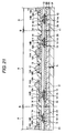
- FIG.12 to FIG.22 are views showing steps of manufacturing the semiconductor device according to the first embodiment of the present invention.
- the same reference symbols are affixed to the same constituent portions as those of the semiconductor device 10 according to the first embodiment.
- B denotes a position along which a dicer cuts the semiconductor substrate 31 into individual pieces (referred to as a "cutting position B" hereinafter).
- the semiconductor chip 11 having the semiconductor integrated circuit 22, the electrode pads 23 and the protection film 24 is formed on the upper surface 31A side of a semiconductor substrate 31, which has a plurality of semiconductor device forming areas A, by the well-known approaches.
- the semiconductor device forming area A gives the area in which the semiconductor device 10 is formed.
- the semiconductor substrate 31 serves as the semiconductor substrate 21 explained above (see FIG.11 ) when such substrate is thinned and is cut in cutting positions B in steps described later.
- a silicon wafer can be used as the semiconductor substrate 31 .
- a thickness T 3 of the semiconductor substrate 31 can be set to 500 ⁇ m to 775 ⁇ m, for example.
- A1 or an alloy containing A1 e.g., Al-Si-Cu alloy
- the protection film 24 for example, a SiN film, a PSG film, or the like can be used.
- the internal connection terminal 12 is formed on a plurality of electrode pads 23 of the structure shown in FIG.12 respectively.
- the internal connection terminal 12 for example, Au bump, Au plating film, metal film consisting of a Ni film formed by the electroless plating method and an Au film covering this Ni film can be used.
- the Au bump can be formed by the bonding method, for example. In this case, there is variation in height of a plurality of internal connection terminals 12 formed in steps shown in FIG.13 .
- the insulating layer 13 is formed to cover the plurality of semiconductor chips 11 and the plurality of internal connection terminals 12 on the side on which the internal connection terminals 12 are provided (insulating layer forming step).
- a sheet-like insulating resin with tackiness e.g., Non Conductive Film (NCF)
- NCF Non Conductive Paste
- NCP Non Conductive Paste
- ACF Anisotropic Conductive Film
- the insulating layer 13 is formed by pasting the sheet-like insulating resin on the upper surface side of the structure shown in FIG.13 . Also, when the paste-like insulating resin is used as the insulating layer 13, the paste-like insulating resin is formed on the upper surface side of the structure shown in FIG.13 by the printing method, and then the insulating resin is semi-cured by prebaking. This semi-cured insulating resin has an adhesive property.
- a thickness T 4 of the insulating layer 13 can be set to 20 ⁇ m to 100 ⁇ m, for example.
- a metal layer 33 is formed on the upper surface 13A of the insulating layer 13 (metal layer forming step).
- a Cu foil is used as the metal layer 33, and then this Cu foil is laminated on the upper surface 13A of the insulating layer 13.
- a thickness T 5 of the metal layer 33 can be set to 12 ⁇ m, for example.
- the metal layer 33 serves as the wiring patterns 14, 15 when this layer is etched in steps shown in FIG.17 as described later.
- a flat plate 34 is arranged on the upper surface 33A of the metal layer 33 in a state that the structure shown in FIG.15 is being heated, and then a lower surface 33B of the metal layer 33 is brought into contact with the upper end portions 12-1 of the plurality of internal connection terminals 12 by pushing the whole metal layer 33 using the flat plate 34 (metal layer pushing step). Therefore, contact surfaces 12A whose surface is made substantially flat respectively are formed on the upper end portions 12-1 of the plurality of internal connection terminals 12.
- the flat plate 34 is removed from the metal layer 33 after the contact surfaces 12A whose surface is made substantially flat respectively are formed on the upper end portions 12-1 of the plurality of internal connection terminals 12.
- a pressure applied to push the metal layer 33 for example, 4MPa (30 mN/cm 2 ) can be used.
- a thickness T 2 of the insulating layer 13 obtained after the metal layer pushing step can be set to 10 ⁇ m to 60 ⁇ m, for example.
- a height H 1 of the internal connection terminal 12 is substantially equal to a thickness T 2 of the insulating layer 13, and can be set concretely to 30 ⁇ m, for example.
- the lower surface 33B of the metal layer 33 is brought into contact with the upper end portions 12-1 of the plurality of internal connection terminals 12 by pushing the whole metal layer 33 such that the contact surfaces 12A whose surface is made substantially flat respectively are formed on the upper end portions 12-1 of the plurality of internal connection terminals 12. Therefore, the step of making the height of the plurality of internal connection terminals 12 uniform and the polishing step of exposing the contact surfaces 12A of the upper end portions 12-1 of the plurality of internal connection terminals 12 from the insulating layer 13, both required in the related art, can be omitted. As a result, the number of manufacturing steps can be reduced, and thus a production cost of the semiconductor device 10 can be reduced.
- a pressing tool 36 having projection portions 37 is prepared, then the projection portions 37 are brought into contact with portions of the metal layer 33 arranged on the upper end portions 12-1 of the internal connection terminals 12 in a state that the structure shown in FIG. 16 is being heated. Then, the portions of the metal layer 33 arranged on the upper end portions 12-1 of the internal connection terminals 12 are pushed (e.g., 10 gf to 30 gf) by the projection portions 37, so that the recess 12-1A as the first recess are formed in the internal connection terminals 12, and the recess 14B as the second recess are formed in the metal layer 33 (recess forming step).
- the portions of the metal layer 33 corresponding to the recess 14B contact the side surface and the bottom surface of the recess 12-1A of the internal connection terminal 12 respectively. Therefore, contact areas between the metal layer 33 and the upper end portions 12-1 of the internal connection terminals 12 in the recess forming step can be set larger than contact areas between the metal layer 33 and the upper end portions 12-1 of the internal connection terminals 12 in the metal layer pushing step.
- the shape of the projection portion 37 for example, a circular cylinder or a square pillar can be used. Also, when a height H 1 of the internal connection terminal 12 is 30 ⁇ m, an amount of projection C of the projection portion 37 can be set to 10 ⁇ m, for example.
- the metal layer 33 is brought into contact with the contact surfaces 12A of the upper end portions 12-1 of the internal connection terminals 12 by pushing the whole metal layer 33, and then the portions, which contact the upper end portions of the internal connection terminals 12, of the metal layer 33 are pushed such that the recess 12-1A are formed on the internal connection terminals 12 and the recess 14B are formed on the metal layer 33. Therefore, the bottom surface and the side surface of the recess 12-1A formed on the internal connection terminals 12 come into contact with the metal layer 33, and thus contact areas between the internal connection terminals 12 and the wiring patterns 14 can be increased.
- the wiring patterns 14, 15 are formed by etching the metal layer 33 shown in FIG.17 (wiring pattern forming step).
- the patterned resist film (not shown) is formed on the metal layer 33 shown in FIG.17 , and then the metal layer 33 is etched by the etching (e.g., the dry etching or the wet etching) while using this resist film as a mask to form the wiring patterns 14, 15.
- the solder resist 16 having the opening portions 16A, 16B is formed on the insulating film 13 to cover the wiring patterns 14, 15 except the connection portions 14A, 15A.
- the opening portions 16A are formed to expose the connection portion 14A of the wiring pattern 14 respectively.
- the opening portion 16B is formed to expose the connection portion 15A of the wiring pattern 15.
- the external connection terminal 17 is formed on the connection portions 14A, 15A of the wiring patterns 14, 15 respectively.
- the solder bump can be used as the external connection terminal 17, for example.
- the semiconductor substrate 31 is grinded from the lower surface 31 B side of the semiconductor substrate 31 shown in FIG.20 so that a thickness of the semiconductor substrate 31 can be reduced.
- the backside grinder can be used.
- a thickness T 1 of the sheet-like semiconductor substrate 31 can be set to 100 ⁇ m to 300 ⁇ m, for example. Accordingly, the structure corresponding to the semiconductor device 10 is formed in the semiconductor device forming area A.
- a plurality of semiconductor devices 10 are given as individual pieces by cutting the structure shown in FIG.21 along the cutting position B. As a result, the plurality of semiconductor devices 10 are manufactured.
- the lower surface 33B of the metal layer 33 is brought into contact with the upper end portions 12-1 of the plurality of internal connection terminals 12 by pushing the whole metal layer 33 such that the contact surfaces 12A whose surface is made substantially flat respectively are formed on the upper end portions 12-1 of the plurality of internal connection terminals 12. Therefore, the step of making the height of the plurality of internal connection terminals 12 uniform and the polishing step of exposing the contact surfaces 12A of the upper end portions 12-1 of the plurality of internal connection terminals 12 from the insulating layer 13, both required in the related art, can be omitted. As a result, the number of manufacturing steps can be reduced, and thus a production cost of the semiconductor device 10 can be reduced.
- the metal layer 33 is brought into contact with the contact surfaces 12A of the upper end portions 12-1 of the internal connection terminals 12 by pushing the whole metal layer 33, and then the portions, which contact the upper end portions of the internal connection terminals 12, of the metal layer 33 are pushed such that the recess 12-1A are formed on the internal connection terminal 12 and the recess 14B are formed on the metal layer 33. Therefore, the bottom surface and the side surface of the recess 12-1A formed on the internal connection terminal 12 come into contact with the metal layer 33, and thus a contact area between the internal connection terminal 12 and the wiring patterns 14 is increased.
- the adhesion between the internal connection terminal 12 and the wiring patterns 14 can be improved and also such a situation never occurs that the insulating layer 13 is interposed between the internal connection terminal 12 and the wiring patterns 14 (such a situation can be eliminated that a resistance value between the internal connection terminal 12 and the wiring patterns 14 is increased due to the influence of the insulating layer 13), and thus the yield of the semiconductor device 10 can be improved.
- the wiring patterns 14, 15 are formed by etching the metal layer 33 after the recess 12-1A and the recess 14B are formed.
- exemplary embodiments of the present invention are not limited thereto.
- the wiring patterns 14, 15 may be formed by etching the metal layer 33 after the metal layer pushing step shown in FIG.16 , and then the recess 12-1A and the recess 14B may be formed.
- FIG.23 is a sectional view showing the pressing tool
- FIG.24 is a view showing a sectional shape of the recess formed by the pressing tool shown in FIG.23 .
- the recess forming step may be executed by using a pressing tool 41 having a projection portion 42 whose sectional shape shown in FIG.23 is formed into a trapezoid, instead of the pressing tool 36 used in the step shown in FIG.17 .
- a recess 12-1B (whose width is extended gradually upward from the bottom surface of the recess 12-1B) is formed on the upper end portion 12-1 of the internal connection terminal 12, and a recess 14C (whose width is extended gradually upward from the bottom surface of the recess 14C) is formed on the wiring pattern 14.
- FIG.25 is a sectional view showing another pressing tool
- FIG.26 is a view showing a sectional shape of a recess formed by the pressing tool shown in FIG.25 .
- the recess forming step may be executed using a pressing tool 45 having a projection portion 46 having a plurality of projections 47 shown in FIG.25 , instead of the pressing tool 36 used in the step shown in FIG.17 .
- a recess 12-1C to which shapes of the plurality of projections 47 are transferred is formed on the upper end portion 12-1 of the internal connection terminal 12, and a recess 14D to which shapes of the plurality of projections 47 are transferred is formed on the wiring pattern 14.
- a height of the projections 47 can be set to 5 ⁇ m, for example.
- FIG.27 is a sectional view of a semiconductor device according to a second embodiment of the present invention.
- the same reference symbols are affixed to the same constituent portions as those of the semiconductor device 10 of the first embodiment.
- a semiconductor device 50 of the second embodiment is constructed similarly to the semiconductor device 10 except that internal connection terminals 51 are provided in place of the internal connection terminals 12 provided to the semiconductor device 10 of the first embodiment, and recess portions 13C are provided on the insulating layer 13, and recess portions 14E are provided in place of the recess 14B provided on the wiring pattern 14.
- the internal connection terminal 51 has an upper end portion 51-1 whose upper surface 51-1A is shaped into a substantially flat surface.
- the upper surface 51-1A of the upper end portion 51-1 is almost the same level as the upper surface 13A of the insulating layer 13, and contacts the wiring pattern 14.
- a height H 2 of the internal connection terminal 51 is set substantially equal to a thickness T 2 of the insulating layer 13.
- the height H 2 of the internal connection terminal 51 can be set to 10 ⁇ m to 60 ⁇ m, for example.
- As the internal connection terminal 51 for example, Au bump, Au plating film, metal film consisting of a Ni film formed by the electroless plating method and an Au film covering this Ni film can be used.
- the Au bump can be formed by the bonding method, or the plating method, for example.
- the recess portion 13C constitutes a ring-like groove, and is formed on the portion, which is arranged on the outer peripheral portion of the upper end portion 51-1 of the internal connection terminal 51, of the insulating layer 13.
- the recess portion 13C is formed to expose the outer peripheral side surface of the upper end portion 51-1 of the internal connection terminal 51.
- a depth of the recess portion 13C can be set to 15 ⁇ m, for example.
- the recess portion 14E constitutes a ring-like groove, and is formed on the portion, which is arranged over the recess portion 13C, of the wiring pattern 14.
- the portion, which corresponds to the recess portion 14E, of the wiring pattern 14 is arranged to cover the outer peripheral side surface of the upper end portion 51-1 of the internal connection terminal 51.
- the wiring patterns 14 are brought into contact with the upper surfaces 51-1A of the upper end portions 51-1 of the internal connection terminal 51, and the ring-like recess portions 13C are provided in the insulating layer 13 to expose the outer peripheral side surfaces of the upper end portions 51-1 of the internal connection terminals 51 and also the ring-like recess portions 14E are provided on the portions, which are arranged over the recess portions 13C, of the wiring patterns 14 such that the outer peripheral side surfaces of the upper end portions 51-1 of the internal connection terminals 51 are covered with the portions, which are arranged over the recess portions 13C, of the wiring patterns 14. Therefore, the contact areas between the internal connection terminals 51 and the wiring patterns 14 can be increased.
- the adhesion between the internal connection terminal 51 and the wiring patterns 14 can be improved and also such a situation never occurs that the insulating layer 13 is interposed between the internal connection terminal 51 and the wiring patterns 14 (such a situation can be eliminated that a resistance value between the internal connection terminal 51 and the wiring pattern 14 is increased due to the influence of the insulating layer 13), and thus the yield of the semiconductor device 50 can be improved.
- FIG.28 is a view showing steps of manufacturing the semiconductor device according to the second embodiment of the present invention.
- the same reference symbols are affixed to the structure shown in FIG.17 described in the first embodiment and the same constituent portions as those of the semiconductor device 50 of the second embodiment.
- the method of manufacturing the semiconductor device of the second embodiment will be described hereunder.
- the structure shown in FIG. 16 (the flat plate 34 shown in FIG. 16 is excluded from the constituent elements of the structure shown in FIG.16 ) is formed by applying the similar processes to the steps described in the first embodiment and shown in FIG. 12 to FIG. 16 .
- a pressing tool 55 having ring-like projection portions 56 is prepared, and the portions of the metal layer 33 which are arranged on the outer peripheral portions of the upper end portions 51-1 of the internal connection terminals 51 provided to the structure shown in FIG. 16 are pushed by the projection portions 56 (a pressure is set to 10 gf to 30 gf, for example) such that the recess portions 13C as the first recess portion are formed on the insulating layer 13 and also the recess portions 14E as the ring-like second recess portions are formed on the metal layer 33 (recess portion forming step).
- a width of the projection portion 56 can be set to 5 ⁇ m, for example. Also, when a height H 2 of the internal connection terminal 51 is set to 30 ⁇ m, an amount of projection E of the projection portion 56 can be set to 15 ⁇ m, for example.
- the portions, which are arranged on the outer peripheral portions of the upper end portions 51-1 of the internal connection terminals 51, of the metal layer 33 are pushed using the pressing tool 55 having the ring-like projection portions 56 such that the ring-like recess portions 14E are formed on the metal layer 33 and the recess portions 13C are formed on the insulating layer 13. Therefore, the outer peripheral side surfaces of the upper end portions 51-1 of the internal connection terminals 51 are covered with the portions of the metal layer 33 in which the recess portion 14E is formed respectively, and thus the contact areas between the metal layer 33 and the upper end portions 51-1 of the internal connection terminals 51 in the recess forming step can be set larger than those in the metal layer pushing step.
- the contact areas between the internal connection terminals 51 and the wiring patterns 14 can be increased.
- the adhesion between the internal connection terminal 51 and the wiring patterns 14 can be improved and also such a situation never occurs that the insulating layer 13 is interposed between the internal connection terminal 51 and the wiring patterns 14 (such a situation can be eliminated that a resistance value between the internal connection terminal 51 and the wiring pattern 14 is increased due to the influence of the insulating layer 13), and thus the yield of the semiconductor device 50 can be improved.
- the plurality of semiconductor devices 50 are manufactured by applying the similar processes to the steps described in the first embodiment and shown in FIG.18 to FIG.22 .
- the metal layer 33 is brought into contact with the upper end portions 51-1 of the internal connection terminals 51 by pushing the overall metal layer 33, and then the portions, which are arranged on the outer peripheral portions of the upper end portions 51-1 of the internal connection terminals 51, of the metal layer 33 are pushed such that the recess portions 13C for exposing the outer peripheral surface of the upper end portion 51-1 of the internal connection terminal 51 respectively are formed in the insulating layer 13 and the recess portions 14E are formed on the metal layer 33. Therefore, the outer peripheral surfaces of the upper end portions of the internal connection terminals 51 comes into contact with the metal layer 33, and thus the contact areas between the internal connection terminals 51 and the metal layer 33 can be increased.
- the adhesion between the internal connection terminal 51 and the wiring patterns 14 can be improved and also such a situation never occurs that the insulating layer 13 is interposed between the internal connection terminal 51 and the wiring patterns 14 (such a situation can be eliminated that a resistance value between the internal connection terminal 51 and the wiring pattern 14 is increased due to the influence of the insulating layer 13), and thus the yield of the semiconductor device 50 can be improved.
- the wiring patterns 14, 15 are formed by etching the metal layer 33 after the recess portions 13C, 14E are formed.
- exemplary embodiments of the present invention are not limited thereto.
- the wiring patterns 14, 15 may be formed by etching the metal layer 33 after the metal layer pushing step, and then the recess portions 13C, 14E may be formed.
- the shape of the projection portion 56 of the pressing tool 55 is not limited to the present embodiment.
- the projection portion 56 may be formed like a discontinuous ring shape.
Abstract
Description
- The present disclosure relates to a method of manufacturing a semiconductor device and, more particularly, to a method of manufacturing a semiconductor device, in which upper end portions of internal connection terminals, which are provided to electrode pads of a plurality of semiconductor chips formed on a semiconductor substrate, are electrically connected to wiring patterns. The present disclosure also relates to a semiconductor device.
-
FIG.1 is a sectional view of a semiconductor device in the related art. - By reference to
FIG.1 , a semiconductor device 100 (e.g., a chip-size package) in the related art includes asemiconductor chip 101,internal connection terminals 102, aresin layer 103,wiring patterns 104, asolder resist 106, andexternal connection terminals 107. - The
semiconductor chip 101 has a sheet-like semiconductor substrate 110, a semiconductor integratedcircuit 111, a plurality ofelectrode pads 112, and aprotection film 113. The semiconductor integratedcircuit 111 is provided on the surface side of thesemiconductor substrate 110. The semiconductor integratedcircuit 111 is composed of a diffusion layer, an insulating layer, vias, wirings, and the like. The plurality ofelectrode pads 112 are provided on the semiconductor integratedcircuit 111. The plurality ofelectrode pads 112 are connected electrically to the wirings provided on the semiconductor integratedcircuit 111. Theprotection film 113 is provided on the semiconductor integratedcircuit 111. Theprotection film 113 is a film for protecting the semiconductor integratedcircuit 111. - The
internal connection terminals 102 are provided on theelectrode pads 112 respectively. Upper surfaces of upper end portions of theinternal connection terminals 102 are exposed from theresin layer 103. The upper end portions of theinternal connection terminals 102 are connected to thewiring patterns 104. Theresin layer 103 is provided to cover thesemiconductor substrate 110 on the side on which theinternal connection terminals 102 are provided. - The
wiring patterns 104 are provided on theresin layer 103. Thewiring patterns 104 are connected to theinternal connection terminals 102 respectively. Thewiring patterns 104 are connected electrically to theelectrode pads 112 via theinternal connection terminals 102. Thewiring patterns 104 have an external connectionterminal providing area 104A, on which theexternal connection terminal 107 is provided, respectively. Thesolder resist 106 is provided on theresin layer 103 to cover thewiring patterns 104 except the external connectionterminal providing areas 104A. -
FIG.2 to FIG.10 are views showing steps of manufacturing the semiconductor device in the related art. InFIG.2 to FIG.10 , the same reference symbols are affixed to the same constituent portions as those of thesemiconductor device 100 shown inFIG.1 in the related art. - At first, in steps shown in
FIG.2 , thesemiconductor chip 101 having the semiconductor integratedcircuit 111, the plurality ofelectrode pads 112, and theprotection film 113 is formed on the surface side of thesemiconductor substrate 110. A thinning process is not applied to thesemiconductor substrate 110 yet. Then, in steps shown inFIG.3 , theinternal connection terminals 102 are formed on the plurality ofelectrode pads 112 respectively. In this stage, there is variation in height of the plurality ofinternal connection terminals 102. - Then, in steps shown in
FIG.4 , aflat plate 115 is pushed against the upper end portions of the plurality ofinternal connection terminals 102, and thus respective heights of a plurality ofinternal connection terminals 102 are set uniformly. Then, in steps shown inFIG.5 , theresin layer 103 is formed to cover thesemiconductor chip 101 and theinternal connection terminals 102 on the side on which theinternal connection terminals 102 are formed. - Then, in steps shown in
FIG.6 , theresin layer 103 is polished untilupper surfaces 102A of the upper end portions of theinternal connection terminals 102 are exposed from theresin layer 103. At this time, the polishing is carried out until anupper surface 103A of theresin layer 103 is almost same level as theupper surfaces 102A of the upper end portions of theinternal connection terminals 102. - Then, in steps shown in
FIG.7 , thewiring patterns 104 are formed on theupper surface 103A of theresin layer 103. Then, in steps shown inFIG.8 , thesolder resist 106 is formed on theresin layer 103 such that this resist covers thewiring patterns 104 except the external connectionterminal providing areas 104A. - Then, in steps shown in
FIG.9 , thesemiconductor substrate 110 is polished from the back surface side to reduce a thickness of thesemiconductor substrate 110. Then, in steps shown inFIG.10 , theexternal connection terminal 107 is formed on the external connectionterminal providing areas 104A respectively. As a result, thesemiconductor device 100 is manufactured (see e.g., Japanese Patent No.3614828 - However, in the method of manufacturing the
semiconductor device 100 in the related art, the step of making the height of the plurality ofinternal connection terminals 102 uniform and the step of exposing theupper surfaces 102A of the plurality ofinternal connection terminals 102 from theresin layer 103 by polishing theresin layer 103 are required. Therefore, such a problem existed that the number of steps is increased and thus a production cost of thesemiconductor device 100 is increased. - Also, upon polishing the
resin layer 103, it is difficult to remove theresin layer 103 existing on theupper surfaces 102A of the upper end portions of theinternal connection terminals 102 with good precision. Therefore, theresin layer 103 still remains on theupper surfaces 102A of the upper end portions of theinternal connection terminals 102. As a result, such a problem existed that adhesion between theinternal connection terminals 102 and thewiring patterns 104 is degraded (in the worst case, peeling occurs between theinternal connection terminals 102 and the wiring patterns 104), a resistance value between theinternal connection terminals 102 and thewiring patterns 104 is increased. Thus, the yield of thesemiconductor device 100 is lowered. - Exemplary embodiments of the present invention address the above disadvantages and other disadvantages not described above. However, the present invention is not required to overcome the disadvantages described above, and thus, an exemplary embodiment of the present invention may not overcome any of the problems described above. In view of the above, a method of manufacturing a semiconductor device according to
independent claims 1 and 4, and a semiconductor device according toindependent claim 12 are provided. Further advantages, features, aspects and details of the invention are evident from the dependent claims, the description and the drawings. - It is an aspect of the present invention to provide a method of manufacturing a semiconductor device, capable of reducing a production cost of the semiconductor device and also improving yields of the semiconductor device by reducing the number of steps.
- According to one or more aspects of the present invention, in a method of manufacturing a semiconductor device, the method includes the successive steps of:
- (a) providing a semiconductor substrate;
- (b) forming a plurality of semiconductor chips having electrode pads on the semiconductor substrate;
- (c) forming internal connection terminals on the electrode pads;
- (d) forming an insulating layer on the plurality of semiconductor chips to cover the internal connection terminals;
- (e) forming a metal layer on the insulating layer;
- (f) pushing a whole area of the metal layer to bring the metal layer into contact with upper end portions of the internal connection terminals;
- (g) pushing portions of the metal layer which contact the upper end portions of the internal connection terminals, thereby forming first recesses in the internal connection terminals, and thereby forming second recesses in the metal layer; and
- (h) forming wiring patterns by etching the metal layer.
- According to one or more aspects of the present invention, contact areas between the metal layer and the upper end portions of the internal connection terminals after step (g) are larger than those after step (f) and before step (g).
- According to one or more aspects of the present invention, in step (g), the metal layer is brought into contact with bottom surfaces and side surfaces of the first recesses.
- According to one or more aspects of the present invention, in a method of manufacturing a semiconductor device, the method includes the successive steps of:
- (a) providing a semiconductor substrate;
- (b) forming a plurality of semiconductor chips having electrode pads on the semiconductor substrate;
- (c) forming internal connection terminals on the electrode pads;
- (d) forming an insulating layer on the plurality of semiconductor chips to cover the internal connection terminals;
- (e) forming a metal layer on the insulating layer;
- (f) pushing a whole area of the metal layer to bring the metal layer into contact with upper end portions of the internal connection terminals;
- (g) forming wiring patterns by etching the metal layer; and
- (h) pushing portions of the wiring patterns which contact the upper end portions of the internal connection terminals, thereby forming first recesses in the internal connection terminals, and thereby forming second recesses in the wiring patterns.
- (a) providing a semiconductor substrate;
- (b) forming a plurality of semiconductor chips having electrode pads on the semiconductor substrate;
- (c) forming internal connection terminals on the electrode pads;
- (d) forming an insulating layer on the plurality of semiconductor chips to cover the internal connection terminals;
- (e) forming a metal layer on the insulating layer;
- (f) pushing a whole area of the metal layer to bring the metal layer into contact with upper end portions of the internal connection terminals;
- (g) in an arbitrary order, the following steps (g1) and (g2), namely
- (g1) forming wiring patterns by etching the metal layer; and
- (g2) pushing portions of the metal layer (or, if already formed, of the wiring patterns) which contact the upper end portions of the internal connection terminals, thereby forming first recesses in the internal connection terminals, and thereby forming second recesses in the wiring patterns.
- According to one or more aspects of the present invention, contact areas between the wiring patterns and the upper end portions of the internal connection terminals after step (h) are larger than contact areas between the metal layer and the upper end portions of the internal connection terminals after step (f) and before step (h).
- According to one or more aspects of the present invention, in step (h), the wiring patterns are brought into contact with bottom surfaces and side surfaces of the first recess.
- According to one or more aspects of the present invention, step (g) includes:
- pushing portions of the metal layer which contact outer peripheral portions of the upper end portions of the internal connection terminals.
- According to one or more aspects of the present invention, after step (g), at least a part of outer peripheral side surfaces of the upper end portions of the internal connection terminals is covered with portions of the metal layer provided on the first recesses.
- According to one or more aspects of the present invention, step (h) includes:
- pushing portions of the wiring patterns which contact outer peripheral portions of the upper end portions of the internal connection terminals.
- According to one or more aspects of the present invention, after step (h), at least a part of outer peripheral side surfaces of the upper end portions of the internal connection terminals is covered with the wiring patterns.
- According to one or more aspects of the present invention, in step (e), a Cu foil is laminated on the insulating layer
- According to one or more aspects of the present invention, a semiconductor device includes:
- a semiconductor substrate;
- a semiconductor chip formed on the semiconductor substrate and having an electrode pad;
- an insulating layer formed on the semiconductor chip;
- an internal connection terminal formed on the electrode pad and having a first recess, the first recess being exposed from the insulating layer;
- a wiring pattern formed on the insulating layer and having a second recess, the second recess being provided in an area corresponding to an area in which the first recess is provided, wherein the wiring pattern contacts the internal connection terminal in which the first recess is provided;
- a solder resist formed on the wiring pattern and having an opening through which a part of the wiring pattern is exposed; and
- an external connection terminal formed on the exposed wiring pattern.
- According to the present invention, not only a reduction in a production cost of the semiconductor device but also improvement in yields of the semiconductor device can be achieved by reducing the number of steps.
- Other aspects and advantages of the present invention will be apparent from the following description, the drawings, and the claims.
The invention is also directed to apparatuses for carrying out the disclosed methods and including apparatus parts for performing each described method steps. These method steps may be performed by way of hardware components, a computer programmed by appropriate software, by any combination of the two or in any other manner. Furthermore, the invention is also directed to methods by which the described apparatus operates. It includes method steps for carrying out every function of the apparatus or manufacturing every part of the apparatus. - The above and other aspects, features and advantages of the present invention will be more apparent from the following more particular description thereof, presented in conjunction with the following drawings wherein:
-
FIG.1 is a sectional view of a semiconductor device in the related art; -
FIG.2 is a view (#1) showing steps of manufacturing the semiconductor device in the related art; -
FIG.3 is a view (#2) showing steps of manufacturing the semiconductor device in the related art; -
FIG.4 is a view (#3) showing steps of manufacturing the semiconductor device in the related art; -
FIG.5 is a view (#4) showing steps of manufacturing the semiconductor device in the related art; -
FIG.6 is a view (#5) showing steps of manufacturing the semiconductor device in the related art; -
FIG.7 is a view (#6) showing steps of manufacturing the semiconductor device in the related art; -
FIG.8 is a view (#7) showing steps of manufacturing the semiconductor device in the related art; -
FIG.9 is a view (#8) showing steps of manufacturing the semiconductor device in the related art; -
FIG.10 is a view (#9) showing steps of manufacturing the semiconductor device in the related art; -
FIG.11 is a sectional view of a semiconductor device according to a first embodiment of the present invention; -
FIG.12 is a view (#1) showing steps of manufacturing the semiconductor device according to the first embodiment of the present invention; -
FIG.13 is a view (#2) showing steps of manufacturing the semiconductor device according to the first embodiment of the present invention; -
FIG.14 is a view (#3) showing steps of manufacturing the semiconductor device according to the first embodiment of the present invention; -
FIG.15 is a view (#4) showing steps of manufacturing the semiconductor device according to the first embodiment of the present invention; -
FIG.16 is a view (#5) showing steps of manufacturing the semiconductor device according to the first embodiment of the present invention; -
FIG.17 is a view (#6) showing steps of manufacturing the semiconductor device according to the first embodiment of the present invention; -
FIG.18 is a view (#7) showing steps of manufacturing the semiconductor device according to the first embodiment of the present invention; -
FIG.19 is a view (#8) showing steps of manufacturing the semiconductor device according to the first embodiment of the present invention; -
FIG.20 is a view (#9) showing steps of manufacturing the semiconductor device according to the first embodiment of the present invention; -
FIG.21 is a view (#10) showing steps of manufacturing the semiconductor device according to the first embodiment of the present invention; -
FIG.22 is a view (#11) showing steps of manufacturing the semiconductor device according to the first embodiment of the present invention; -
FIG.23 is a sectional view showing a pressing tool; -
FIG.24 is a view showing a sectional shape of a recess formed by the pressing tool shown inFIG.23 ; -
FIG.25 is a sectional view showing another pressing too;. -
FIG.26 is a view showing a sectional shape of a recess formed by the pressing tool shown inFIG.25 ; -
FIG.27 is a sectional view of a semiconductor device according to a second embodiment of the present invention; and -
FIG.28 is a view showing steps of manufacturing the semiconductor device according to the second embodiment of the present invention. - Exemplary embodiments of the present invention will be described with reference to the drawings hereinafter.
-
FIG.11 is a sectional view of a semiconductor device according to a first embodiment of the present invention. - By reference to
FIG.11 , asemiconductor device 10 includes asemiconductor chip 11,internal connection terminals 12, an insulatinglayer 13,wiring patterns external connection terminals 17. - The
semiconductor chip 11 has asemiconductor substrate 21, a semiconductor integratedcircuit 22,electrode pads 23, and aprotection film 24. Thesemiconductor substrate 21 is used to form the semiconductor integratedcircuit 22. Thesemiconductor substrate 21 is shaped into a thin plate. A thickness T1 of thesemiconductor substrate 21 can be set to 100 to 300 µm, for example. As thesemiconductor substrate 21, for example, a silicon substrate (concretely, individual pieces of the sheet-like silicon wafer) can be used. - The semiconductor integrated
circuit 22 is provided on theupper surface 21A side of thesemiconductor substrate 21. The semiconductor integratedcircuit 22 is composed of a diffusion layer (not shown) formed on thesemiconductor substrate 21, an insulating layer (not shown) laminated on thesemiconductor substrate 21, vias (not shown) provided in the laminated insulating layer, wirings (not shown), and the like. - The
electrode pad 23 is provided in plural on the semiconductor integratedcircuit 22. Theelectrode pads 23 are connected electrically to the wirings (not shown) provided on the semiconductor integratedcircuit 22. As the material of theelectrode pads 23, for example, Al or an alloy containing Al (e.g., Al-Si-Cu alloy) can be used. - The
protection film 24 is provided on the semiconductor integratedcircuit 22. Theprotection film 24 is the film for protecting the semiconductor integratedcircuit 22. As theprotection film 24, for example, a SiN film, a PSG film, and the like can be used. - The
internal connection terminals 12 are provided on theelectrode pads 23. Lower end portions of theinternal connection terminals 12 are connected electrically to the semiconductor integratedcircuit 22 via theelectrode pads 23. Upper end portions 12-1 of theinternal connection terminals 12 have a recess 12-1A as a first recess on a portion opposing to thewiring pattern 14 respectively. A side surface and a bottom surface of the recess 12-1A and an upper surface of the upper end portion 12-1 of theinternal connection terminal 12 contact thewiring pattern 14. Accordingly, thewirings 14 and the semiconductor integratedcircuit 22 are connected electrically mutually via theinternal connection terminals 12. When a diameter of the upper end portion 12-1 of theinternal connection terminal 12 is 40 µm, a diameter of the recess 12-1A can be set to 20 µm, for example. In this case, a depth of the recess 12-1A can be set to 10 µm, for example. - A height H1 of the
internal connection terminal 12 is substantially equal to a thickness T2 of the insulatinglayer 13. A height H1 of theinternal connection terminal 12 can be set to 10 µm to 60 µm, for example. As theinternal connection terminal 12, for example, Au bump, Au plating film, metal film consisting of a Ni film formed by the electroless plating method and an Au film covering the Ni film can be used. The Au bump can be formed by the bonding method, the plating method, or the like, for example. - The insulating
layer 13 is provided to cover respective areas of theinternal connection terminals 12 and thesemiconductor chip 11 except the upper surfaces of the upper end portion 12-1 and the recess 12-1A of theinternal connection terminals 12. As the insulatinglayer 13, for example, a sheet-like insulating resin with tackiness (e.g., Non Conductive Film (NCF)), a paste-like insulating resin (e.g., Non Conductive Paste (NCP) ), an anisotropic conductive resin (e.g., Anisotropic Conductive Film (ACF)), or the like can be used. A thickness T2 of the insulatinglayer 13 can be set to 10 µm to 60 µm, for example. - The
wiring patterns 14 are provided on the upper end portions 12-1 of theinternal connection terminals 12 and the insulatinglayer 13 arranged near the upper end portions 12-1. Thewiring pattern 14 has aconnection portion 14A and arecess 14B as a second recess. Theconnection portion 14A is formed on the insulatinglayer 13. Theexternal connection terminal 17 is provided on theconnection portion 14A. - The
recess 14B is formed in the portion, which is arranged on the recess 12-1A of theinternal connection terminals 12, of thewiring pattern 14. The portion of thewiring pattern 14 which corresponds to a forming area of therecess 14B contacts the side surface and the bottom surface of the recess 12-1A of theinternal connection terminal 12. Thewiring patterns 14 constructed as above are connected electrically to the semiconductor integratedcircuit 22 via theinternal connection terminals 12. - In this manner, the recess 12-1A is provided in the
internal connection terminal 12 and also therecess 14B is provided on the portion of thewiring pattern 14 which corresponds to the recess 12-1A Thus, the portion, which corresponds to the forming area of therecess 14B, of thewiring pattern 14 is brought into contact with the side surface and the bottom surface of the recess 12-1A. Therefore, a contact area between theinternal connection terminal 12 and thewiring pattern 14 is increased, and thus a resistance value between theinternal connection terminal 12 and thewiring pattern 14 can be reduced. - As the
wiring pattern 14, for example, a Cu film can be used. In this case, a diffusion preventing film (not shown) may be formed between thewiring pattern 14 and theexternal connection terminal 17. As the diffusion preventing film, for example, a Ni/Au obtained by forming sequentially a Ni layer and an Au layer on thewiring pattern 14 can be used. When a Cu film is used as thewiring pattern 14, a thickness of thewiring pattern 14 can be set to 12 µm, for example. - The
wiring pattern 15 is provided on anupper surface 13A of the insulatinglayer 13. Thewiring pattern 15 has aconnection portion 15A. Theexternal connection terminal 17 is provided on theconnection portion 15A. As thewiring pattern 15, for example, a Cu film can be used. In this case, a diffusion preventing film (not shown) may be formed between thewiring pattern 15 and theexternal connection terminal 17. As the diffusion preventing film, for example, a Ni/Au obtained by forming sequentially a Ni layer and an Au layer on thewiring pattern 15 can be used. When a Cu film is used as thewiring pattern 15, a thickness of thewiring pattern 15 can be set to 12 µm, for example. - The solder resist 16 is provided on the insulating
layer 13 to cover respective portions of thewiring patterns connection portions portions 16A from which theconnection portion 14A is exposed respectively, and anopening portion 16B from which theconnection portion 15A is exposed. - The
external connection terminal 17 is provided on theconnection portions wiring patterns external connection terminals 17 are the terminals that are connected electrically to the pads provided on a mounting substrate (not shown) such as a motherboard, respectively. As theexternal connection terminal 17, for example, a solder bump can be used. - According to the semiconductor device of the present embodiment, the recess 12-1A is provided in the
internal connection terminal 12 that connects electrically thewiring pattern 14 and thesemiconductor chip 11. Also, therecess 14B is provided on the portion, which is arranged on the recess 12-1A, of thewiring pattern 14 such that the portion, which corresponds to the forming area of therecess 14B, of thewiring pattern 14 is brought into contact with the side surface and the bottom surface of the recess 12-1A. Therefore, a contact area between theinternal connection terminal 12 and thewiring pattern 14 can be increased, and thus a resistance value between theinternal connection terminal 12 and thewiring pattern 14 can be reduced. As a result, the yield of thesemiconductor device 10 can be improved. -
FIG.12 to FIG.22 are views showing steps of manufacturing the semiconductor device according to the first embodiment of the present invention. InFIG.12 to FIG.22 , the same reference symbols are affixed to the same constituent portions as those of thesemiconductor device 10 according to the first embodiment. Also, inFIG.12 to FIG.22 , B denotes a position along which a dicer cuts thesemiconductor substrate 31 into individual pieces (referred to as a "cutting position B" hereinafter). - At first, in steps shown in
FIG.12 , thesemiconductor chip 11 having the semiconductor integratedcircuit 22, theelectrode pads 23 and theprotection film 24 is formed on theupper surface 31A side of asemiconductor substrate 31, which has a plurality of semiconductor device forming areas A, by the well-known approaches. The semiconductor device forming area A gives the area in which thesemiconductor device 10 is formed. Thesemiconductor substrate 31 serves as thesemiconductor substrate 21 explained above (seeFIG.11 ) when such substrate is thinned and is cut in cutting positions B in steps described later. - As the
semiconductor substrate 31, for example, a silicon wafer can be used. When the silicon wafer is used as thesemiconductor substrate 31, a thickness T3 of thesemiconductor substrate 31 can be set to 500 µm to 775 µm, for example. As the material of theelectrode pad 23, for example, A1 or an alloy containing A1 (e.g., Al-Si-Cu alloy) can be used. As theprotection film 24, for example, a SiN film, a PSG film, or the like can be used. - Then, in steps shown in
FIG.13 , theinternal connection terminal 12 is formed on a plurality ofelectrode pads 23 of the structure shown inFIG.12 respectively. As theinternal connection terminal 12, for example, Au bump, Au plating film, metal film consisting of a Ni film formed by the electroless plating method and an Au film covering this Ni film can be used. The Au bump can be formed by the bonding method, for example. In this case, there is variation in height of a plurality ofinternal connection terminals 12 formed in steps shown inFIG.13 . - Then, in steps shown in
FIG. 14 , the insulatinglayer 13 is formed to cover the plurality ofsemiconductor chips 11 and the plurality ofinternal connection terminals 12 on the side on which theinternal connection terminals 12 are provided (insulating layer forming step). As the insulatinglayer 13, for example, a sheet-like insulating resin with tackiness (e.g., Non Conductive Film (NCF) ), a paste-like insulating resin (e.g., Non Conductive Paste (NCP) ), an anisotropic conductive resin (e.g., Anisotropic Conductive Film (ACF) ) can be used. When the sheet-like insulating resin with tackiness is used, the insulatinglayer 13 is formed by pasting the sheet-like insulating resin on the upper surface side of the structure shown inFIG.13 . Also, when the paste-like insulating resin is used as the insulatinglayer 13, the paste-like insulating resin is formed on the upper surface side of the structure shown inFIG.13 by the printing method, and then the insulating resin is semi-cured by prebaking. This semi-cured insulating resin has an adhesive property. A thickness T4 of the insulatinglayer 13 can be set to 20 µm to 100 µm, for example. - Then, in steps shown in
FIG.15 , ametal layer 33 is formed on theupper surface 13A of the insulating layer 13 (metal layer forming step). Concretely, for example, a Cu foil is used as themetal layer 33, and then this Cu foil is laminated on theupper surface 13A of the insulatinglayer 13. A thickness T5 of themetal layer 33 can be set to 12 µm, for example. Themetal layer 33 serves as thewiring patterns FIG.17 as described later. - Then, in steps shown in
FIG. 16 , aflat plate 34 is arranged on theupper surface 33A of themetal layer 33 in a state that the structure shown inFIG.15 is being heated, and then alower surface 33B of themetal layer 33 is brought into contact with the upper end portions 12-1 of the plurality ofinternal connection terminals 12 by pushing thewhole metal layer 33 using the flat plate 34 (metal layer pushing step). Therefore,contact surfaces 12A whose surface is made substantially flat respectively are formed on the upper end portions 12-1 of the plurality ofinternal connection terminals 12. - The
flat plate 34 is removed from themetal layer 33 after the contact surfaces 12A whose surface is made substantially flat respectively are formed on the upper end portions 12-1 of the plurality ofinternal connection terminals 12. As a pressure applied to push themetal layer 33, for example, 4MPa (30 mN/cm2) can be used. A thickness T2 of the insulatinglayer 13 obtained after the metal layer pushing step can be set to 10 µm to 60 µm, for example. Also, a height H1 of theinternal connection terminal 12 is substantially equal to a thickness T2 of the insulatinglayer 13, and can be set concretely to 30 µm, for example. - In this manner, the
lower surface 33B of themetal layer 33 is brought into contact with the upper end portions 12-1 of the plurality ofinternal connection terminals 12 by pushing thewhole metal layer 33 such that the contact surfaces 12A whose surface is made substantially flat respectively are formed on the upper end portions 12-1 of the plurality ofinternal connection terminals 12. Therefore, the step of making the height of the plurality ofinternal connection terminals 12 uniform and the polishing step of exposing the contact surfaces 12A of the upper end portions 12-1 of the plurality ofinternal connection terminals 12 from the insulatinglayer 13, both required in the related art, can be omitted. As a result, the number of manufacturing steps can be reduced, and thus a production cost of thesemiconductor device 10 can be reduced. - Then, in steps shown in
FIG.17 , apressing tool 36 havingprojection portions 37 is prepared, then theprojection portions 37 are brought into contact with portions of themetal layer 33 arranged on the upper end portions 12-1 of theinternal connection terminals 12 in a state that the structure shown inFIG. 16 is being heated. Then, the portions of themetal layer 33 arranged on the upper end portions 12-1 of theinternal connection terminals 12 are pushed (e.g., 10 gf to 30 gf) by theprojection portions 37, so that the recess 12-1A as the first recess are formed in theinternal connection terminals 12, and therecess 14B as the second recess are formed in the metal layer 33 (recess forming step). - According to the above step, the portions of the
metal layer 33 corresponding to therecess 14B contact the side surface and the bottom surface of the recess 12-1A of theinternal connection terminal 12 respectively. Therefore, contact areas between themetal layer 33 and the upper end portions 12-1 of theinternal connection terminals 12 in the recess forming step can be set larger than contact areas between themetal layer 33 and the upper end portions 12-1 of theinternal connection terminals 12 in the metal layer pushing step. As the shape of theprojection portion 37, for example, a circular cylinder or a square pillar can be used. Also, when a height H1 of theinternal connection terminal 12 is 30 µm, an amount of projection C of theprojection portion 37 can be set to 10 µm, for example. - In this manner, the
metal layer 33 is brought into contact with the contact surfaces 12A of the upper end portions 12-1 of theinternal connection terminals 12 by pushing thewhole metal layer 33, and then the portions, which contact the upper end portions of theinternal connection terminals 12, of themetal layer 33 are pushed such that the recess 12-1A are formed on theinternal connection terminals 12 and therecess 14B are formed on themetal layer 33. Therefore, the bottom surface and the side surface of the recess 12-1A formed on theinternal connection terminals 12 come into contact with themetal layer 33, and thus contact areas between theinternal connection terminals 12 and thewiring patterns 14 can be increased. As a result, adhesion between theinternal connection terminals 12 and thewiring patterns 14 can be improved and also such a situation never occurs that the insulatinglayer 13 is interposed between theinternal connection terminals 12 and the wiring patterns 14 (such a situation can be eliminated that a resistance value between theinternal connection terminal 12 and thewiring patterns 14 is increased due to the influence of the insulating layer 13), and thus the yield of thesemiconductor device 10 can be improved. - Then, in steps shown in
FIG.18 , thewiring patterns metal layer 33 shown inFIG.17 (wiring pattern forming step). Concretely, for example, the patterned resist film (not shown) is formed on themetal layer 33 shown inFIG.17 , and then themetal layer 33 is etched by the etching (e.g., the dry etching or the wet etching) while using this resist film as a mask to form thewiring patterns - Then, in steps shown in
FIG.19 , the solder resist 16 having the openingportions film 13 to cover thewiring patterns connection portions portions 16A are formed to expose theconnection portion 14A of thewiring pattern 14 respectively. Theopening portion 16B is formed to expose theconnection portion 15A of thewiring pattern 15. - Then, in steps shown in
FIG.20 , theexternal connection terminal 17 is formed on theconnection portions wiring patterns external connection terminal 17, for example, the solder bump can be used. - Then, in steps shown in
FIG.21 , thesemiconductor substrate 31 is grinded from thelower surface 31 B side of thesemiconductor substrate 31 shown inFIG.20 so that a thickness of thesemiconductor substrate 31 can be reduced. In order to reduce a thickness of thesemiconductor substrate 31, for example, the backside grinder can be used. After grinding, a thickness T1 of the sheet-like semiconductor substrate 31 can be set to 100 µm to 300 µm, for example. Accordingly, the structure corresponding to thesemiconductor device 10 is formed in the semiconductor device forming area A. - Then, in steps shown in
FIG.22 , a plurality ofsemiconductor devices 10 are given as individual pieces by cutting the structure shown inFIG.21 along the cutting position B. As a result, the plurality ofsemiconductor devices 10 are manufactured. - According to the method of manufacturing the semiconductor device of the present embodiment, the
lower surface 33B of themetal layer 33 is brought into contact with the upper end portions 12-1 of the plurality ofinternal connection terminals 12 by pushing thewhole metal layer 33 such that the contact surfaces 12A whose surface is made substantially flat respectively are formed on the upper end portions 12-1 of the plurality ofinternal connection terminals 12. Therefore, the step of making the height of the plurality ofinternal connection terminals 12 uniform and the polishing step of exposing the contact surfaces 12A of the upper end portions 12-1 of the plurality ofinternal connection terminals 12 from the insulatinglayer 13, both required in the related art, can be omitted. As a result, the number of manufacturing steps can be reduced, and thus a production cost of thesemiconductor device 10 can be reduced. - Also, the
metal layer 33 is brought into contact with the contact surfaces 12A of the upper end portions 12-1 of theinternal connection terminals 12 by pushing thewhole metal layer 33, and then the portions, which contact the upper end portions of theinternal connection terminals 12, of themetal layer 33 are pushed such that the recess 12-1A are formed on theinternal connection terminal 12 and therecess 14B are formed on themetal layer 33. Therefore, the bottom surface and the side surface of the recess 12-1A formed on theinternal connection terminal 12 come into contact with themetal layer 33, and thus a contact area between theinternal connection terminal 12 and thewiring patterns 14 is increased. As a result, the adhesion between theinternal connection terminal 12 and thewiring patterns 14 can be improved and also such a situation never occurs that the insulatinglayer 13 is interposed between theinternal connection terminal 12 and the wiring patterns 14 (such a situation can be eliminated that a resistance value between theinternal connection terminal 12 and thewiring patterns 14 is increased due to the influence of the insulating layer 13), and thus the yield of thesemiconductor device 10 can be improved. - In the above embodiment, the
wiring patterns metal layer 33 after the recess 12-1A and therecess 14B are formed. However, exemplary embodiments of the present invention are not limited thereto. In this case, thewiring patterns metal layer 33 after the metal layer pushing step shown inFIG.16 , and then the recess 12-1A and therecess 14B may be formed. -
FIG.23 is a sectional view showing the pressing tool, andFIG.24 is a view showing a sectional shape of the recess formed by the pressing tool shown inFIG.23 . - The recess forming step may be executed by using a
pressing tool 41 having aprojection portion 42 whose sectional shape shown inFIG.23 is formed into a trapezoid, instead of thepressing tool 36 used in the step shown inFIG.17 . In this case, as shown inFIG.24 , a recess 12-1B (whose width is extended gradually upward from the bottom surface of the recess 12-1B) is formed on the upper end portion 12-1 of theinternal connection terminal 12, and arecess 14C (whose width is extended gradually upward from the bottom surface of therecess 14C) is formed on thewiring pattern 14. -
FIG.25 is a sectional view showing another pressing tool, andFIG.26 is a view showing a sectional shape of a recess formed by the pressing tool shown inFIG.25 . - The recess forming step may be executed using a
pressing tool 45 having aprojection portion 46 having a plurality ofprojections 47 shown inFIG.25 , instead of thepressing tool 36 used in the step shown inFIG.17 . In this case, as shown inFIG.26 , a recess 12-1C to which shapes of the plurality ofprojections 47 are transferred is formed on the upper end portion 12-1 of theinternal connection terminal 12, and arecess 14D to which shapes of the plurality ofprojections 47 are transferred is formed on thewiring pattern 14. - In this manner, when the recess forming step is executed using the
pressing tool 45 having theprojection portion 46 having the plurality ofprojections 47, contact areas between thewiring patterns 14 and theinternal connection terminals 12 can be further increased. A height of theprojections 47 can be set to 5 µm, for example. -
FIG.27 is a sectional view of a semiconductor device according to a second embodiment of the present invention. InFIG.27 , the same reference symbols are affixed to the same constituent portions as those of thesemiconductor device 10 of the first embodiment. - By reference to
FIG.27 , asemiconductor device 50 of the second embodiment is constructed similarly to thesemiconductor device 10 except thatinternal connection terminals 51 are provided in place of theinternal connection terminals 12 provided to thesemiconductor device 10 of the first embodiment, andrecess portions 13C are provided on the insulatinglayer 13, andrecess portions 14E are provided in place of therecess 14B provided on thewiring pattern 14. - The
internal connection terminal 51 has an upper end portion 51-1 whose upper surface 51-1A is shaped into a substantially flat surface. The upper surface 51-1A of the upper end portion 51-1 is almost the same level as theupper surface 13A of the insulatinglayer 13, and contacts thewiring pattern 14. A height H2 of theinternal connection terminal 51 is set substantially equal to a thickness T2 of the insulatinglayer 13. The height H2 of theinternal connection terminal 51 can be set to 10 µm to 60 µm, for example. As theinternal connection terminal 51, for example, Au bump, Au plating film, metal film consisting of a Ni film formed by the electroless plating method and an Au film covering this Ni film can be used. The Au bump can be formed by the bonding method, or the plating method, for example. - The
recess portion 13C constitutes a ring-like groove, and is formed on the portion, which is arranged on the outer peripheral portion of the upper end portion 51-1 of theinternal connection terminal 51, of the insulatinglayer 13. Therecess portion 13C is formed to expose the outer peripheral side surface of the upper end portion 51-1 of theinternal connection terminal 51. A depth of therecess portion 13C can be set to 15 µm, for example. - The
recess portion 14E constitutes a ring-like groove, and is formed on the portion, which is arranged over therecess portion 13C, of thewiring pattern 14. The portion, which corresponds to therecess portion 14E, of thewiring pattern 14 is arranged to cover the outer peripheral side surface of the upper end portion 51-1 of theinternal connection terminal 51. - According to the semiconductor device of the present embodiment, the
wiring patterns 14 are brought into contact with the upper surfaces 51-1A of the upper end portions 51-1 of theinternal connection terminal 51, and the ring-like recess portions 13C are provided in the insulatinglayer 13 to expose the outer peripheral side surfaces of the upper end portions 51-1 of theinternal connection terminals 51 and also the ring-like recess portions 14E are provided on the portions, which are arranged over therecess portions 13C, of thewiring patterns 14 such that the outer peripheral side surfaces of the upper end portions 51-1 of theinternal connection terminals 51 are covered with the portions, which are arranged over therecess portions 13C, of thewiring patterns 14. Therefore, the contact areas between theinternal connection terminals 51 and thewiring patterns 14 can be increased. As a result, the adhesion between theinternal connection terminal 51 and thewiring patterns 14 can be improved and also such a situation never occurs that the insulatinglayer 13 is interposed between theinternal connection terminal 51 and the wiring patterns 14 (such a situation can be eliminated that a resistance value between theinternal connection terminal 51 and thewiring pattern 14 is increased due to the influence of the insulating layer 13), and thus the yield of thesemiconductor device 50 can be improved. -
FIG.28 is a view showing steps of manufacturing the semiconductor device according to the second embodiment of the present invention. InFIG.28 , the same reference symbols are affixed to the structure shown inFIG.17 described in the first embodiment and the same constituent portions as those of thesemiconductor device 50 of the second embodiment. - By reference to
FIG.28 , the method of manufacturing the semiconductor device of the second embodiment will be described hereunder. At first, the structure shown inFIG. 16 (theflat plate 34 shown inFIG. 16 is excluded from the constituent elements of the structure shown inFIG.16 ) is formed by applying the similar processes to the steps described in the first embodiment and shown inFIG. 12 to FIG. 16 . - Then, in steps shown in
FIG.28 , apressing tool 55 having ring-like projection portions 56 is prepared, and the portions of themetal layer 33 which are arranged on the outer peripheral portions of the upper end portions 51-1 of theinternal connection terminals 51 provided to the structure shown inFIG. 16 are pushed by the projection portions 56 (a pressure is set to 10 gf to 30 gf, for example) such that therecess portions 13C as the first recess portion are formed on the insulatinglayer 13 and also therecess portions 14E as the ring-like second recess portions are formed on the metal layer 33 (recess portion forming step). - A width of the
projection portion 56 can be set to 5 µm, for example. Also, when a height H2 of theinternal connection terminal 51 is set to 30 µm, an amount of projection E of theprojection portion 56 can be set to 15 µm, for example. - In this manner, the portions, which are arranged on the outer peripheral portions of the upper end portions 51-1 of the
internal connection terminals 51, of themetal layer 33 are pushed using thepressing tool 55 having the ring-like projection portions 56 such that the ring-like recess portions 14E are formed on themetal layer 33 and therecess portions 13C are formed on the insulatinglayer 13. Therefore, the outer peripheral side surfaces of the upper end portions 51-1 of theinternal connection terminals 51 are covered with the portions of themetal layer 33 in which therecess portion 14E is formed respectively, and thus the contact areas between themetal layer 33 and the upper end portions 51-1 of theinternal connection terminals 51 in the recess forming step can be set larger than those in the metal layer pushing step. - According to the above process, the contact areas between the
internal connection terminals 51 and thewiring patterns 14 can be increased. As a result, the adhesion between theinternal connection terminal 51 and thewiring patterns 14 can be improved and also such a situation never occurs that the insulatinglayer 13 is interposed between theinternal connection terminal 51 and the wiring patterns 14 (such a situation can be eliminated that a resistance value between theinternal connection terminal 51 and thewiring pattern 14 is increased due to the influence of the insulating layer 13), and thus the yield of thesemiconductor device 50 can be improved. - Then, the plurality of
semiconductor devices 50 are manufactured by applying the similar processes to the steps described in the first embodiment and shown inFIG.18 to FIG.22 . - According to the method of manufacturing the semiconductor device of the present embodiment, the
metal layer 33 is brought into contact with the upper end portions 51-1 of theinternal connection terminals 51 by pushing theoverall metal layer 33, and then the portions, which are arranged on the outer peripheral portions of the upper end portions 51-1 of theinternal connection terminals 51, of themetal layer 33 are pushed such that therecess portions 13C for exposing the outer peripheral surface of the upper end portion 51-1 of theinternal connection terminal 51 respectively are formed in the insulatinglayer 13 and therecess portions 14E are formed on themetal layer 33. Therefore, the outer peripheral surfaces of the upper end portions of theinternal connection terminals 51 comes into contact with themetal layer 33, and thus the contact areas between theinternal connection terminals 51 and themetal layer 33 can be increased. As a result, the adhesion between theinternal connection terminal 51 and thewiring patterns 14 can be improved and also such a situation never occurs that the insulatinglayer 13 is interposed between theinternal connection terminal 51 and the wiring patterns 14 (such a situation can be eliminated that a resistance value between theinternal connection terminal 51 and thewiring pattern 14 is increased due to the influence of the insulating layer 13), and thus the yield of thesemiconductor device 50 can be improved. - In the above embodiment, the
wiring patterns metal layer 33 after therecess portions wiring patterns metal layer 33 after the metal layer pushing step, and then therecess portions projection portion 56 of thepressing tool 55 is not limited to the present embodiment. For example, theprojection portion 56 may be formed like a discontinuous ring shape. - While the present invention has been shown and described with reference to certain exemplary embodiments thereof, it will be understood by those skilled in the art that various changes in form and details may be made therein without departing from the spirit and scope of the invention as defined by the appended claims. It is aimed, therefore, to cover in the appended claim all such changes and modifications as fall within the true spirit and scope of the present invention.
This application is based on and claims priority from Japanese Patent Application No.2007-212949, filed on Aug. 17, 2007
Claims (12)
- A method of manufacturing a semiconductor device, the method comprising the successive steps of:(a) providing a semiconductor substrate (21);(b) forming a plurality of semiconductor chips (11) having electrode pads (23) on the semiconductor substrate;(c) forming internal connection terminals (12) on the electrode pads;(d) forming an insulating layer (13) on the plurality of semiconductor chips to cover the internal connection terminals;(e) forming a metal layer (33) on the insulating layer;(f) pushing a whole area of the metal layer (33) to bring the metal layer into contact with upper end portions (12-1) of the internal connection terminals;(g) pushing portions of the metal layer (33) which contact the upper end portions (12-1) of the internal connection terminals (12), thereby forming first recesses (12-1A) in the internal connection terminals, and thereby forming second recesses (14A) in the metal layer; and(h) forming wiring patterns (14) by etching the metal layer.
- The method according to claim 1, wherein contact areas between the metal layer and the upper end portions of the internal connection terminals after step (g) are larger than those after step (f) and before step (g).
- The method according to claim 1 or 2, wherein in step (g), the metal layer is brought into contact with bottom surfaces and side surfaces of the first recesses.
- A method of manufacturing a semiconductor device, the method comprising the successive steps of:(a) providing a semiconductor substrate (21);(b) forming a plurality of semiconductor chips (11) having electrode pads (23) on the semiconductor substrate;(c) forming internal connection terminals (12) on the electrode pads;(d) forming an insulating layer (13) on the plurality of semiconductor chips to cover the internal connection terminals;(e) forming a metal layer (33) on the insulating layer;(f) pushing a whole area of the metal layer to bring the metal layer into contact with upper end portions (12-1) of the internal connection terminals;(g) forming wiring patterns (14) by etching the metal layer; and(h) pushing portions of the wiring patterns (14) which contact the upper end portions (12-1) of the internal connection terminals, thereby forming first recesses (12-1A) in the internal connection terminals, and thereby forming second recesses (14A) in the wiring patterns.
- The method according to claim 4, wherein contact areas between the wiring patterns and the upper end portions of the internal connection terminals after step (h) are larger than contact areas between the metal layer and the upper end portions of the internal connection terminals after step (f) and before step (h).
- The method according to claim 4 or 5, wherein, in step (h), the wiring patterns are brought into contact with bottom surfaces and side surfaces of the first recess.
- The method according to any one of claims 1 to 3, wherein step (g) comprises:pushing portions of the metal layer which contact outer peripheral portions of the upper end portions of the internal connection terminals.
- The method according to any one of claims 1 to 3 or 7, wherein, after step (g), at least a part of outer peripheral side surfaces of the upper end portions of the internal connection terminals is covered with portions of the metal layer provided on the first recesses.
- The method according to any one of claims 4 to 6, wherein step (h) comprises:pushing portions of the wiring patterns which contact outer peripheral portions of the upper end portions of the internal connection terminals.
- The method according to any one of claims 4 to 6 or 9, wherein, after step (h), at least a part of outer peripheral side surfaces of the upper end portions of the internal connection terminals is covered with the wiring patterns.
- The method according to any one of the preceding claims, wherein in step (e), a Cu foil is laminated on the insulating layer.
- A semiconductor device, comprising:a semiconductor substrate (21);a semiconductor chip (11) formed on the semiconductor substrate and having an electrode pad (23);an insulating layer (13) formed on the semiconductor chip;an internal connection terminal (12) formed on the electrode pad and having a first recess (12-1A), the first recess being exposed from the insulating layer;a wiring pattern (14) formed on the insulating layer and having a second recess (14A), the second recess being provided in an area corresponding to an area in which the first recess is provided, wherein the wiring pattern contacts the internal connection terminal in which the first recess is provided;a solder resist (16) formed on the wiring pattern and having an opening (16A) through which a part of the wiring pattern is exposed; andan external connection terminal (17) formed on the exposed wiring pattern.
Applications Claiming Priority (1)
| Application Number | Priority Date | Filing Date | Title |
|---|---|---|---|
| JP2007212949A JP5048420B2 (en) | 2007-08-17 | 2007-08-17 | Semiconductor device and manufacturing method thereof |
Publications (2)
| Publication Number | Publication Date |
|---|---|
| EP2026380A2 true EP2026380A2 (en) | 2009-02-18 |
| EP2026380A3 EP2026380A3 (en) | 2009-11-18 |
Family
ID=39766905
Family Applications (1)
| Application Number | Title | Priority Date | Filing Date |
|---|---|---|---|
| EP08162325A Withdrawn EP2026380A3 (en) | 2007-08-17 | 2008-08-13 | Method of manufacturing semiconductor device |
Country Status (5)
| Country | Link |
|---|---|
| US (2) | US7719123B2 (en) |
| EP (1) | EP2026380A3 (en) |
| JP (1) | JP5048420B2 (en) |
| KR (1) | KR20090018576A (en) |
| CN (1) | CN101369546A (en) |
Families Citing this family (3)
| Publication number | Priority date | Publication date | Assignee | Title |
|---|---|---|---|---|
| JP2010103300A (en) * | 2008-10-23 | 2010-05-06 | Sanyo Electric Co Ltd | Semiconductor device, and method of manufacturing the same |
| US7956471B2 (en) * | 2008-11-12 | 2011-06-07 | Freescale Semiconductor, Inc. | Mold and substrate for use with mold |
| JP5383460B2 (en) * | 2009-12-04 | 2014-01-08 | 新光電気工業株式会社 | Manufacturing method of semiconductor device |
Citations (3)
| Publication number | Priority date | Publication date | Assignee | Title |
|---|---|---|---|---|
| EP1005086A2 (en) | 1998-11-26 | 2000-05-31 | Shinko Electric Industries Co. Ltd. | Metal foil having bumps, circuit substrate having the metal foil, and semiconductor device having the circuit substrate |
| JP2002313985A (en) | 2002-04-05 | 2002-10-25 | Oki Electric Ind Co Ltd | Method of manufacturing chip size package |
| EP1933377A2 (en) | 2006-10-24 | 2008-06-18 | Shinko Electric Industries Co., Ltd. | Semiconductor device and method for manufacturing the same |
Family Cites Families (5)
| Publication number | Priority date | Publication date | Assignee | Title |
|---|---|---|---|---|
| US5148265A (en) * | 1990-09-24 | 1992-09-15 | Ist Associates, Inc. | Semiconductor chip assemblies with fan-in leads |
| US5412539A (en) * | 1993-10-18 | 1995-05-02 | Hughes Aircraft Company | Multichip module with a mandrel-produced interconnecting decal |
| JP4707283B2 (en) * | 2001-08-30 | 2011-06-22 | イビデン株式会社 | Semiconductor chip |
| JP3717899B2 (en) * | 2002-04-01 | 2005-11-16 | Necエレクトロニクス株式会社 | Semiconductor device and manufacturing method thereof |
| JP2004193497A (en) * | 2002-12-13 | 2004-07-08 | Nec Electronics Corp | Chip-size package and manufacturing method thereof |
-
2007
- 2007-08-17 JP JP2007212949A patent/JP5048420B2/en active Active
-
2008
- 2008-08-13 US US12/190,789 patent/US7719123B2/en active Active
- 2008-08-13 EP EP08162325A patent/EP2026380A3/en not_active Withdrawn
- 2008-08-13 KR KR1020080079244A patent/KR20090018576A/en not_active Application Discontinuation
- 2008-08-15 CN CNA2008101459885A patent/CN101369546A/en active Pending
-
2010
- 2010-03-30 US US12/749,758 patent/US8148254B2/en active Active
Patent Citations (3)
| Publication number | Priority date | Publication date | Assignee | Title |
|---|---|---|---|---|
| EP1005086A2 (en) | 1998-11-26 | 2000-05-31 | Shinko Electric Industries Co. Ltd. | Metal foil having bumps, circuit substrate having the metal foil, and semiconductor device having the circuit substrate |
| JP2002313985A (en) | 2002-04-05 | 2002-10-25 | Oki Electric Ind Co Ltd | Method of manufacturing chip size package |
| EP1933377A2 (en) | 2006-10-24 | 2008-06-18 | Shinko Electric Industries Co., Ltd. | Semiconductor device and method for manufacturing the same |
Also Published As
| Publication number | Publication date |
|---|---|
| US7719123B2 (en) | 2010-05-18 |
| US20090045529A1 (en) | 2009-02-19 |
| US20100184257A1 (en) | 2010-07-22 |
| EP2026380A3 (en) | 2009-11-18 |
| KR20090018576A (en) | 2009-02-20 |
| US8148254B2 (en) | 2012-04-03 |
| JP2009049134A (en) | 2009-03-05 |
| JP5048420B2 (en) | 2012-10-17 |
| CN101369546A (en) | 2009-02-18 |
Similar Documents
| Publication | Publication Date | Title |
|---|---|---|
| US8169065B2 (en) | Stackable circuit structures and methods of fabrication thereof | |
| US7727875B2 (en) | Grooving bumped wafer pre-underfill system | |
| US7772091B2 (en) | Manufacturing method of semiconductor apparatus comprising alignment patterns in scribe regions | |
| CN101154606B (en) | Manufacturing method of semiconductor device | |
| US20040251525A1 (en) | Methods and apparatus for packaging integrated circuit devices | |
| JP2003347441A (en) | Semiconductor element, semiconductor device, and method for producing semiconductor element | |
| KR20060088518A (en) | Semiconductor device and manufacturing method thereof | |
| EP2040294B1 (en) | Method of manufacturing a semiconductor device | |
| US7964493B2 (en) | Method of manufacturing semiconductor device | |
| WO2005093829A1 (en) | Semiconductor package having an interfacial adhesive layer | |
| EP2026380A2 (en) | Method of manufacturing semiconductor device | |
| JP5139039B2 (en) | Semiconductor device and manufacturing method thereof | |
| US20100112786A1 (en) | Method of manufacturing semiconductor device | |
| US8232639B2 (en) | Semiconductor-device mounted board and method of manufacturing the same | |
| EP1926144B1 (en) | Semiconductor device and manufacturing method thereof | |
| JP2004119472A (en) | Semiconductor device, its manufacturing method, circuit board, and electronic apparatus | |
| JP2005191485A (en) | Semiconductor device |
Legal Events
| Date | Code | Title | Description |
|---|---|---|---|
| PUAI | Public reference made under article 153(3) epc to a published international application that has entered the european phase |
Free format text: ORIGINAL CODE: 0009012 |
|
| AK | Designated contracting states |
Kind code of ref document: A2 Designated state(s): AT BE BG CH CY CZ DE DK EE ES FI FR GB GR HR HU IE IS IT LI LT LU LV MC MT NL NO PL PT RO SE SI SK TR |
|
| AX | Request for extension of the european patent |
Extension state: AL BA MK RS |
|
| PUAL | Search report despatched |
Free format text: ORIGINAL CODE: 0009013 |
|
| AK | Designated contracting states |
Kind code of ref document: A3 Designated state(s): AT BE BG CH CY CZ DE DK EE ES FI FR GB GR HR HU IE IS IT LI LT LU LV MC MT NL NO PL PT RO SE SI SK TR |
|
| AX | Request for extension of the european patent |
Extension state: AL BA MK RS |
|
| 17P | Request for examination filed |
Effective date: 20100518 |
|
| AKX | Designation fees paid |
Designated state(s): DE |
|
| 17Q | First examination report despatched |
Effective date: 20100714 |
|
| STAA | Information on the status of an ep patent application or granted ep patent |
Free format text: STATUS: THE APPLICATION HAS BEEN WITHDRAWN |
|
| 18W | Application withdrawn |
Effective date: 20150313 |