EP2025481A2 - Press device and method for producing laminated timber - Google Patents
Press device and method for producing laminated timber Download PDFInfo
- Publication number
- EP2025481A2 EP2025481A2 EP08014262A EP08014262A EP2025481A2 EP 2025481 A2 EP2025481 A2 EP 2025481A2 EP 08014262 A EP08014262 A EP 08014262A EP 08014262 A EP08014262 A EP 08014262A EP 2025481 A2 EP2025481 A2 EP 2025481A2
- Authority
- EP
- European Patent Office
- Prior art keywords
- press
- delivery device
- arrangement
- rooms
- wood
- Prior art date
- Legal status (The legal status is an assumption and is not a legal conclusion. Google has not performed a legal analysis and makes no representation as to the accuracy of the status listed.)
- Granted
Links
Images
Classifications
-
- B—PERFORMING OPERATIONS; TRANSPORTING
- B27—WORKING OR PRESERVING WOOD OR SIMILAR MATERIAL; NAILING OR STAPLING MACHINES IN GENERAL
- B27M—WORKING OF WOOD NOT PROVIDED FOR IN SUBCLASSES B27B - B27L; MANUFACTURE OF SPECIFIC WOODEN ARTICLES
- B27M3/00—Manufacture or reconditioning of specific semi-finished or finished articles
- B27M3/0013—Manufacture or reconditioning of specific semi-finished or finished articles of composite or compound articles
- B27M3/0026—Manufacture or reconditioning of specific semi-finished or finished articles of composite or compound articles characterised by oblong elements connected laterally
- B27M3/0053—Manufacture or reconditioning of specific semi-finished or finished articles of composite or compound articles characterised by oblong elements connected laterally using glue
-
- B—PERFORMING OPERATIONS; TRANSPORTING
- B27—WORKING OR PRESERVING WOOD OR SIMILAR MATERIAL; NAILING OR STAPLING MACHINES IN GENERAL
- B27D—WORKING VENEER OR PLYWOOD
- B27D3/00—Veneer presses; Press plates; Plywood presses
- B27D3/02—Veneer presses; Press plates; Plywood presses with a plurality of press plates, i.e. multi- platen hot presses
-
- B—PERFORMING OPERATIONS; TRANSPORTING
- B27—WORKING OR PRESERVING WOOD OR SIMILAR MATERIAL; NAILING OR STAPLING MACHINES IN GENERAL
- B27M—WORKING OF WOOD NOT PROVIDED FOR IN SUBCLASSES B27B - B27L; MANUFACTURE OF SPECIFIC WOODEN ARTICLES
- B27M3/00—Manufacture or reconditioning of specific semi-finished or finished articles
- B27M3/0013—Manufacture or reconditioning of specific semi-finished or finished articles of composite or compound articles
- B27M3/0026—Manufacture or reconditioning of specific semi-finished or finished articles of composite or compound articles characterised by oblong elements connected laterally
- B27M3/0033—Manufacture or reconditioning of specific semi-finished or finished articles of composite or compound articles characterised by oblong elements connected laterally by a plurality of clamps each used with similar articles and each functionning similarly but time-delayed
-
- B—PERFORMING OPERATIONS; TRANSPORTING
- B30—PRESSES
- B30B—PRESSES IN GENERAL
- B30B7/00—Presses characterised by a particular arrangement of the pressing members
- B30B7/02—Presses characterised by a particular arrangement of the pressing members having several platens arranged one above the other
- B30B7/023—Feeding or discharging means
Definitions
- the invention relates to a press arrangement with the preamble features of claim 1 and a method for producing laminated beams according to the preamble of claim 15.
- the binders are made of wood or wood-based materials. If the binders are made of glued laminated timber, then pre-sorted and liberated woods are used here.
- a load-bearing capacity of up to 80 percent can be achieved compared to solid wood. In comparison to solid wood, larger cross-sections and the production of curved beams are also possible.
- the glued laminated timber elements offer advantages in terms of weight and chemical resistance at a similar price.
- the lumbers or lamellae are first subjected to a quality sorting and package formation. It can also be a wedge galvanizing of the slats are carried out in order to realize larger margins of the finished glued laminated timber elements.
- the slats are then glued inserted into a special press and pressed. After setting the glue, the removal of the glued laminated timber element from the press and the final planing, packaging and removal of the finished binder takes place.
- Cycle time determining during the production of the binder is the processing and curing time of the glue used in each case.
- adhesives condensation resins such as melamine or Resorcinharze, but also one- or multi-component, moisture-curing polyurethane or emulsion polymer isocyanate adhesives.
- the liquid adhesives cure under the influence of material and humidity and / or ambient and material temperature to a high-strength, water-resistant and permanent adhesive joint.
- the processing time the so-called. "open time" of the adhesive, which is between 20 minutes and two hours for previously used adhesives. During this period, stacking and alignment of the slats, the introduction of the stacks into the press and the pressurization of the stacks is possible.
- the curing time follows, which is between one and seven hours.
- the laminated beam must remain in the press under pressure, so that the splices meet the initial strength requirements after the completion of the curing time.
- the ultimate strength is usually reached after several hours, with a whereabouts of the workpieces in the press is no longer mandatory.
- the DE 102 24 793 proposes a plant for the production of glued laminated timber, in which two presses are arranged in parallel in the production line and in which the laminated wood leaving the gluing station is selectively fed to one of the two presses via a turnout device. After the pressing process, the pressed workpieces are in turn fed via a turnout device for further processing.
- a disadvantage of this system is to be considered that no linear transfer of the prepared wood or material stack within the production line is possible, but always a deflection of the stack takes place, which can lead to slippage of the stack components. It will therefore require an additional alignment step before closing the press, which can be difficult to clock in the very short "open" processing time of the adhesive and leads to any accumulation of material leads to the entire wood or material stack must be discarded.
- the object of the present invention is therefore to provide a press arrangement which overcomes the aforementioned disadvantages, enables a rapid and flexible loading of several presses with glued and aligned wood or material stacks within the processing and curing times of the adhesives used and which due to a linear conveyance of the wood or material stacks or finished pressed workpieces in the transfer direction does not necessitate a realignment of the wood or material stacks in the press room.
- a corresponding method should be specified.
- the press arrangement according to the invention in particular of presses for the production of glued laminated timber or laminated beams of pressed wood or material stacks, is characterized in that at least one feeder for wood or material stacks, at least two press rooms and at least one independent of the feeder device for pressed wood or Material stacks are provided.
- the press rooms and / or the supply device and / or the delivery device are arranged movable relative to each other. As a result of a movable design of the arrangement elements, these can be aligned by the cycle times, depending on the specification, so that, for example, the discharge of one press room can take place while another press room is already being loaded again.
- the adhesive parameters such as processing time (“open time”) and curing time two or more presses can be arranged side by side, wherein the time interval for loading is selected so that during the entire curing time of the first press more, preferably arranged in parallel press chambers by the movable feeder can be loaded.
- a discharge then takes place from the first loaded press starting in the direction of the last loaded press by a likewise movable delivery device.
- only the press rooms are arranged to be movable and are each moved in front of the feeder, loaded and continued. The discharge takes place in the opposite direction by transferring the respectively to be unloaded press room before the AusGermanvorraum.
- At least one feed device and at least one delivery device are arranged on respective opposite end faces of the press rooms.
- a further reduction of the cycle times is achieved because a linear transfer of the wood or material stack to be pressed through the press rooms is possible.
- the feeder, the press rooms and the Ausgradvorraum preferably synchronizable conveying elements.
- These have, for example, corresponding connection or coupling means, so that after the alignment of the respective arrangement members, a toothing or connection of the respective conveying elements can take place automatically.
- the conveying elements can be identical, i. the feeder as well as press room and execution device, for example, have a roller conveyor for transporting the wood and material stacks or the pressed workpiece.
- the arrangement members have different conveying elements, which are then synchronized via corresponding controls as soon as the elements meet in the production process.
- the feeding device has at least one frame element for aligning the wood or material stacks.
- the frame element of the upstream of the respective press room in the production process feeding device acts on the still unoriented wood or material stacks, for example by sliding leg, by hydraulically or pneumatically acted upon pressure elements in the frame or on rollers that are arranged in or on the frame. At least one of these rollers may be additionally driven to assist in conveying the aligned logs of wood or material into the press room. It can thus take place immediately before feeding into the press room, a flush alignment of the stack components by the corresponding frame member.
- the feeding device and the delivery device are arranged to be stationary and the press spaces to be movable.
- the press spaces and / or the feed device and / or the feed device can be moved freely and / or guided.
- the movement of the arrangement members into their respective predetermined by the processing cycle position can be carried out in the manner of a driverless transport vehicle.
- the respective arrangement member is integrated into a floor-bound conveyor with its own drive, is automatically controlled and guided without contact and has a control system, a device for determining location and for position detection and facilities for data transmission.
- the production facility then additionally has a corresponding infrastructure and the associated peripheral facilities for operating such systems.
- a simpler embodiment of the arrangement provides that the movable assembly members are moved track or rail.
- the use of all common Lineargleit- or linear roller guideways in conjunction with corresponding linear actuators is conceivable.
- the control of the movement of the press rooms and / or the delivery device and / or the delivery device is preferably carried out manually or automatically via a control device.
- a control device can be provided centrally in the manner of a control station for one or more plants or decentralized to each arrangement member.
- the press rooms, the feed device and the delivery device have a central drive and the respective movement of the individual arrangement parts takes place via a corresponding drive control. It is also considered to be recommendable if the press rooms and the feed device and / or the feed device have separate drives.
- the drive is any kind of linear drive conceivable.
- positioning aids in particular variable stop wedges, are provided for the arrangement members which are provided on or in the linear guide used in each case. An adjustment of the positioning aids takes place either manually or automatically.
- the supply device and the delivery device preferably have detection means for the parameters of the wood or material stack or of the finished workpiece.
- detection means may comprise, for example, a displacement sensor which receives the dimensions of the material stack conveyed into the press space and of the executed workpiece.
- optical scanning techniques e.g. The annual ring position of the lamellas and the quality of the visible surfaces are recorded in order to be able to provide information for downstream outstations before the final planing of the workpieces.
- Another measuring element determines the important parameter for the curing time wood and ambient moisture as well as temperature of the material stack, in order to determine the optimal pressing time based on these values.
- the press arrangement according to the invention preferably has a memory and / or evaluation unit for the determined parameters, which is for example connected directly to the control station of the system and either information to the operator or automatically controls the system or adapts it to the determined parameters.
- the delivery device 17 also has corresponding conveying elements 14, the drive 19 of which can be synchronized with the drives 19 of the conveying elements 14 of the press spaces 11 and the feeding device 13.
Abstract
Description
Die Erfindung betrifft eine Pressenanordnung mit den oberbegrifflichen Merkmalen des Anspruchs 1 und ein Verfahren zur Herstellung von Leimbindern nach dem Oberbegriff von Anspruch 15.The invention relates to a press arrangement with the preamble features of claim 1 and a method for producing laminated beams according to the preamble of
Bei der Herstellung von schichtverleimten Bauteilen werden mehrere Holz- oder Werkstofflamellen miteinander zunächst beleimt, dann aufeinandergeschichtet und in geeigneten Pressen zu stabilen Trägern verpresst. Aus diesen Schichtstapeln oder Bindern können große tragende Bauteile mit komplexen Konstruktionen hergestellt werden, da die Binder in beinahe beliebigen Längen und Formen hergestellt werden können. Herkömmlicherweise werden die Binder aus Holz oder Holzwerkstoffen produziert. Werden die Binder aus Brettschichtholz gefertigt, so kommen hier vorsortierte und von Fehlstellen befreite Hölzer zum Einsatz. Durch die Verbindung der Hölzer zu Brettschichtholzelementen lässt sich, bezogen auf identische Querschnitte, eine bis zu 80 Prozent höhere Tragkraft als mit Vollholz erreichen. Im Vergleich zu Vollholz sind darüber hinaus größere Querschnitte und die Herstellung gebogener Träger möglich. Gegenüber reinen Stahl- und Spannbetonkonstruktionen bieten die Brettschichtholzelemente bei ähnlichem Preis Vorteile in Bezug auf Gewicht und chemische Widerstandsfähigkeit.In the production of layer-glued components several wood or material lamellae are glued together first, then stacked and pressed in appropriate presses to form stable carriers. From these layer stacks or binders, large structural components can be made with complex constructions because the binders can be made in almost any length and shape. Traditionally, the binders are made of wood or wood-based materials. If the binders are made of glued laminated timber, then pre-sorted and liberated woods are used here. By connecting the wood to glued laminated timber elements, based on identical cross-sections, a load-bearing capacity of up to 80 percent can be achieved compared to solid wood. In comparison to solid wood, larger cross-sections and the production of curved beams are also possible. Compared to pure steel and prestressed concrete constructions, the glued laminated timber elements offer advantages in terms of weight and chemical resistance at a similar price.
Zur Herstellung der Brettschichtholzelemente werden die Schnitthölzer oder Lamellen zunächst einer Gütesortierung und Paketbildung unterzogen. Es kann auch eine Keilverzinkung der Lamellen durchgeführt werden, um größere Spannbreiten der fertigen Brettschichtholzelemente realisieren zu können. Die Lamellen werden anschließend beleimt in eine spezielle Presse eingeführt und verpresst. Nach Abbinden des Leimes erfolgt die Entnahme des Brettschichtholzelements aus der Presse und die abschließende Hobelung, Verpackung und der Abtransport der fertigen Binder.To produce the glued laminated timber elements, the lumbers or lamellae are first subjected to a quality sorting and package formation. It can also be a wedge galvanizing of the slats are carried out in order to realize larger margins of the finished glued laminated timber elements. The slats are then glued inserted into a special press and pressed. After setting the glue, the removal of the glued laminated timber element from the press and the final planing, packaging and removal of the finished binder takes place.
Taktzeitbestimmend bei der Produktion der Binder ist die Verarbeitungs- und Aushärtezeit des jeweils verwendeten Leims. Als Klebstoffe verwendet werden Kondensationsharze wie beispielsweise Melamin- oder Resorcinharze, aber auch ein- oder mehrkomponentige, feuchtigkeitsvernetzende Polyurethan- oder Emulsion-Polymer-Isocyanatklebstoffe. Die flüssigen Klebstoffe härten unter Einfluss von Material- und Luftfeuchte und/oder Umgebungs- sowie Materialtemperatur zu einer hochfesten, wasserbeständigen und dauerhaften Klebefuge aus. Besondere Bedeutung kommt der Verarbeitungszeit, der sog. "offenen Zeit" des Klebstoffes zu, die bei bisher verwendeten Klebstoffen zwischen 20 Minuten und zwei Stunden beträgt. Während dieser Zeitspanne ist eine Stapelung und Ausrichtung der Lamellen, die Einbringung der Stapel in die Presse und die Druckbeaufschlagung der Stapel möglich. Unmittelbar an die Verarbeitungszeit schließt sich die Aushärtezeit an, die zwischen einer und sieben Stunden beträgt. Während dieser Zeit muss der Leimbinder im druckbeaufschlagten Zustand in der Presse verbleiben, damit die Klebestellen die Anforderungen an die Anfangsfestigkeit nach Abschluss der Aushärtezeit erfüllen. Die Endfestigkeit wird in der Regel erst nach mehreren Stunden erreicht, wobei ein Verbleib der Werkstücke in der Presse hierbei nicht mehr obligatorisch ist. Durch die Verwendung von Einkomponentenklebstoffen werden die Rüstzeiten bereits signifikant verkürzt und zudem Fehlverleimungen infolge von Misch- und Dosierfehlern ausgeschlossen. Zudem bedürfen moderne Klebstoffe keiner Temperaturzugabe und ermöglichen somit wirtschaftliche Fertigungsabläufe.Cycle time determining during the production of the binder is the processing and curing time of the glue used in each case. As adhesives are used condensation resins such as melamine or Resorcinharze, but also one- or multi-component, moisture-curing polyurethane or emulsion polymer isocyanate adhesives. The liquid adhesives cure under the influence of material and humidity and / or ambient and material temperature to a high-strength, water-resistant and permanent adhesive joint. Of particular importance is the processing time, the so-called. "open time" of the adhesive, which is between 20 minutes and two hours for previously used adhesives. During this period, stacking and alignment of the slats, the introduction of the stacks into the press and the pressurization of the stacks is possible. Immediately after the processing time, the curing time follows, which is between one and seven hours. During this time, the laminated beam must remain in the press under pressure, so that the splices meet the initial strength requirements after the completion of the curing time. The ultimate strength is usually reached after several hours, with a whereabouts of the workpieces in the press is no longer mandatory. By using one-component adhesives, the set-up times are already significantly shortened and, in addition, mis-gluing due to mixing and metering errors is ruled out. In addition, modern adhesives require no temperature addition and thus enable economical production processes.
Neuerdings werden jedoch Klebstoffe mit Verarbeitungszeiten von zwei bis fünf Minuten und Aushärtezeiten zwischen acht und 15 Minuten angeboten, die die Taktzeiten bei der Herstellung von Brettschichtholzelementen entsprechend weiter verkürzen. Um diese Taktzeitverkürzung für Produktionssteigerungen bei der Herstellung von Brettschichtholz bzw. Leimbindern nutzen zu können, muss neben einer beschleunigten Bildung der Lamellenstapel auch eine zügige Beschickung der Presse innerhalb der kurzen Bearbeitungszeit sowie die Nutzung von mehreren, auf die ebenfalls verkürzten Aushärtezeiten der Klebstoffe abgestimmten Pressen in Auge gefasst werden.Recently, however, adhesives are offered with processing times of two to five minutes and curing times between eight and 15 minutes, which further shorten the cycle times in the production of glulam elements accordingly. In order to be able to use this cycle time reduction for production increases in the production of glulam or laminated beams, in addition to an accelerated formation of the lamella stack also a rapid loading of the press within the short processing time and the use of several, also on the shortened curing times of the adhesives tuned presses in Be caught.
Die
Als nachteilig an dieser Anlage ist anzusehen, dass kein linearer Transfer der vorbereiteten Holz oder Werkstoffstapel innerhalb der Produktionslinie möglich ist, sondern stets eine Umlenkung des Stapels erfolgt, was zu einem Verrutschen der Stapelbestandteile führen kann. Es wird daher ein zusätzlicher Ausrichtungsschritt vor dem Schließen der Presse nötig, der nur schwer in die sehr kurze "offene" Bearbeitungszeit des Klebstoffes eingetaktet werden kann und bei eventuell auftretendem Materialstau dazu führt, dass der gesamte Holz- oder Werkstoffstapel verworfen werden muss.The
A disadvantage of this system is to be considered that no linear transfer of the prepared wood or material stack within the production line is possible, but always a deflection of the stack takes place, which can lead to slippage of the stack components. It will therefore require an additional alignment step before closing the press, which can be difficult to clock in the very short "open" processing time of the adhesive and leads to any accumulation of material leads to the entire wood or material stack must be discarded.
Aufgabe der vorliegenden Erfindung ist es daher, eine Pressenanordnung zur Verfügung zu stellen, die die vorgenannten Nachteile überwindet, eine zügige und flexible Beschickung mehrerer Pressen mit beleimten und ausgerichteten Holz- oder Werkstoffstapeln innerhalb der Bearbeitungs- und Aushärtezeiten der verwendeten Klebstoffe ermöglicht und die aufgrund einer linearen Förderung der Holz- oder Werkstoffstapel bzw. fertig verpressten Werkstücke in Transferrichtung keine Neuausrichtung der Holz- oder Werkstoffstapel im Pressenraum notwendig macht. Zudem soll ein entsprechendes Verfahren angegeben werden.The object of the present invention is therefore to provide a press arrangement which overcomes the aforementioned disadvantages, enables a rapid and flexible loading of several presses with glued and aligned wood or material stacks within the processing and curing times of the adhesives used and which due to a linear conveyance of the wood or material stacks or finished pressed workpieces in the transfer direction does not necessitate a realignment of the wood or material stacks in the press room. In addition, a corresponding method should be specified.
Diese Aufgabe wird gelöst durch eine Pressenanordnung mit den Merkmalen des Anspruchs 1 bzw. einem Verfahren nach Anspruch 15. Vorteilhafte Weiterbildungen der Erfindung sind Gegenstand der abhängigen Ansprüche.This object is achieved by a press arrangement with the features of claim 1 and a method according to
Die erfindungsgemäße Pressenanordnung, insbesondere von Pressen zur Herstellung von Brettschichtholz oder Leimbindern aus gepressten Holz- oder Werkstoffstapeln, ist dadurch gekennzeichnet, dass wenigstens eine Zuführvorrichtung für Holz- oder Werkstoffstapel, wenigstens zwei Pressenräume und wenigstens eine von der Zuführvorrichtung unabhängige Ausführvorrichtung für gepresste Holz- oder Werkstoffstapel vorgesehen sind. Die Pressenräume und/oder die Zuführvorrichtung und/oder die Ausführvorrichtung sind dabei relativ zueinander bewegbar angeordnet. Durch eine bewegliche Ausbildung der Anordnungselemente können diese je nach Vorgabe durch die Taktzeiten ausgerichtet werden, sodass beispielsweise das Entladen eines Pressenraumes erfolgen kann, während ein weiterer Pressenraum bereits wieder beladen wird. Bedingt durch die Klebstoffparameter wie Bearbeitungszeit ("offene Zeit") und Aushärtezeit können zwei oder mehr Pressen nebeneinander angeordnet werden, wobei das Zeitintervall zur Beladung so gewählt wird, dass während der gesamten Aushärtezeit der ersten Presse weitere, bevorzugt parallel angeordnete Pressenräume durch die bewegbare Zuführvorrichtung beladen werden können. Eine Entladung erfolgt dann von der zuerst beschickten Presse ausgehend in Richtung der letztbeladenen Presse durch eine ebenfalls bewegbare Ausführvorrichtung. In einer weiteren denkbaren Ausgestaltung der Anordnung sind nur die Pressenräume bewegbar angeordnet und werden jeweils vor die Zuführvorrichtung verfahren, beladen und weitergeführt. Die Entladung erfolgt in entgegengesetzter Richtung durch Verbringung des jeweils zu entladenden Pressenraumes vor die Ausführvorrichtung. Dadurch dass sowohl die Pressenräume als auch die Zuführ-/Ausführvorrichtungen relativ zueinander bewegbar sind, lassen sich eine Vielzahl von Belade-/Entladekonfigurationen realisieren und so die ggf. kurzen Bearbeitungs- und Aushärtezeiten der verwendeten Klebstoffe besonders effizient nutzen. Dies gilt auch für das vorgeschlagene Verfahren.The press arrangement according to the invention, in particular of presses for the production of glued laminated timber or laminated beams of pressed wood or material stacks, is characterized in that at least one feeder for wood or material stacks, at least two press rooms and at least one independent of the feeder device for pressed wood or Material stacks are provided. The press rooms and / or the supply device and / or the delivery device are arranged movable relative to each other. As a result of a movable design of the arrangement elements, these can be aligned by the cycle times, depending on the specification, so that, for example, the discharge of one press room can take place while another press room is already being loaded again. Due to the adhesive parameters such as processing time ("open time") and curing time two or more presses can be arranged side by side, wherein the time interval for loading is selected so that during the entire curing time of the first press more, preferably arranged in parallel press chambers by the movable feeder can be loaded. A discharge then takes place from the first loaded press starting in the direction of the last loaded press by a likewise movable delivery device. In a further conceivable embodiment of the arrangement, only the press rooms are arranged to be movable and are each moved in front of the feeder, loaded and continued. The discharge takes place in the opposite direction by transferring the respectively to be unloaded press room before the Ausführvorrichtung. The fact that both the press rooms and the feed / Ausführvorrichtungen are relatively movable, a variety of loading / unloading configurations can be realized and thus use the possibly short processing and curing times of the adhesives used particularly efficient. This also applies to the proposed procedure.
Bevorzugt sind wenigstens eine Zuführvorrichtung und wenigstens eine Ausführvorrichtung an jeweils gegenüberliegenden Stirnseiten der Pressenräume angeordnet. Durch eine derartige Anordnung wird eine weitere Senkung der Taktzeiten erreicht, da ein linearer Transfer der zu verpressenden Holz- oder Werkstoffstapel durch die Pressenräume möglich wird. Durch eine entsprechende Anordnung und Verschiebung der Pressenräume und/oder der unabhängig voneinander bewegbaren Zuführ- bzw. Ausführvorrichtungen kann somit gleichzeitig das Be- und Entladen von wenigstens zwei Pressenräumen durchgeführt werden, ohne Konflikte zwischen den Positionen der Zuführ- bzw. Ausführvorrichtungen zu erzeugen.Preferably, at least one feed device and at least one delivery device are arranged on respective opposite end faces of the press rooms. By such an arrangement, a further reduction of the cycle times is achieved because a linear transfer of the wood or material stack to be pressed through the press rooms is possible. By a corresponding arrangement and displacement of the press rooms and / or the independently movable feed or Ausführvorrichtungen thus loading and unloading of at least two press rooms can be performed simultaneously without creating conflicts between the positions of the feeding or Ausführvorrichtungen.
Um eine reibungslose und unterbrechungsfreie Förderung der Holz- bzw. Werkstoffstapel zu erreichen und um die Be- und Entladung der Pressenräume zügig durchführen zu können, weisen die Zuführvorrichtung, die Pressenräume und die Ausführvorrichtung bevorzugt synchronisierbare Förderelemente auf. Diese verfügen beispielsweise über entsprechende Verbindungs- bzw. Kupplungsmittel, sodass nach dem Ausrichten der jeweiligen Anordnungsglieder eine Verzahnung bzw. Verbindung der jeweiligen Förderelemente automatisiert erfolgen kann. Die Förderelemente können dabei gleichartig sein, d.h. die Zuführvorrichtung ebenso wie Pressenraum und Ausführvorrichtung weisen beispielsweise einen Rollenförderer zum Transport der Holz- und Werkstoffstapel bzw. des verpressten Werkstückes auf. Denkbar ist allerdings auch, dass die Anordnungsglieder über unterschiedliche Förderelemente verfügen, die dann über entsprechende Steuerelemente synchronisiert werden, sobald die Element im Produktionsprozess aufeinandertreffen.In order to achieve a smooth and uninterrupted promotion of wood or material stacks and to perform the loading and unloading of the press room quickly, the feeder, the press rooms and the Ausführvorrichtung preferably synchronizable conveying elements. These have, for example, corresponding connection or coupling means, so that after the alignment of the respective arrangement members, a toothing or connection of the respective conveying elements can take place automatically. The conveying elements can be identical, i. the feeder as well as press room and execution device, for example, have a roller conveyor for transporting the wood and material stacks or the pressed workpiece. However, it is also conceivable that the arrangement members have different conveying elements, which are then synchronized via corresponding controls as soon as the elements meet in the production process.
Als besonders empfehlenswert wird angesehen, wenn die Förderelemente einen gemeinsamen Antrieb aufweisen. Dadurch kann eine Synchronisierung der Förderelemente besonders einfach und schnell erfolgen.It is considered particularly recommendable if the conveying elements have a common drive. As a result, a synchronization of the conveying elements can be done very easily and quickly.
In einer bevorzugten Ausführungsform der Pressenanordnung verfügt die Zuführvorrichtung über wenigstens ein Rahmenelement für die Ausrichtung der Holz- oder Werkstoffstapel. Das Rahmenelement der im Produktionsprozess dem jeweiligen Pressenraum vorgelagerten Zuführvorrichtung beaufschlagt dabei die noch unausgerichteten Holz- oder Werkstoffstapel beispielsweise durch verschiebbare Schenkel, durch hydraulisch oder pneumatisch beaufschlagbare Druckelemente im Rahmen oder über Rollen, die im oder am Rahmen angeordnet sind. Wenigstens eine dieser Rollen kann zusätzlich angetrieben sein, um das Einfördern der ausgerichteten Holz- oder Werkstoffstapel in den Pressenraum zu unterstützen. Es kann somit unmittelbar vor dem Zuführen in den Pressenraum eine bündige Ausrichtung der Stapelbestandteile durch das entsprechende Rahmenelement erfolgen.In a preferred embodiment of the press arrangement, the feeding device has at least one frame element for aligning the wood or material stacks. The frame element of the upstream of the respective press room in the production process feeding device acts on the still unoriented wood or material stacks, for example by sliding leg, by hydraulically or pneumatically acted upon pressure elements in the frame or on rollers that are arranged in or on the frame. At least one of these rollers may be additionally driven to assist in conveying the aligned logs of wood or material into the press room. It can thus take place immediately before feeding into the press room, a flush alignment of the stack components by the corresponding frame member.
Je nach Transferlinienkonfiguration und Produktionslayout wird es als besonders günstig angesehen, wenn die Zuführvorrichtung und die Ausführvorrichtung stationär und die Pressenräume bewegbar angeordnet sind. Somit entfällt eine Anpassung der der Zuführvorrichtung vorgelagerten bzw. der Ausführvorrichtung nachgelagerten Bearbeitungsstationen und es wird ein kontinuierlicher Lineartransfer der vorbereiteten Holz- bzw. Werkstoffstapel sowie der verpressten Werkstücke möglich.Depending on the transfer line configuration and production layout, it is considered to be particularly favorable if the feeding device and the delivery device are arranged to be stationary and the press spaces to be movable. Thus, an adjustment of the upstream of the feeder or the delivery device downstream processing stations and there is a continuous linear transfer of the prepared wood or material stack and the compressed workpieces possible.
Als besonders günstig erweist es sich, wenn die Pressenräume und/oder die Zuführvorrichtung und/oder die Ausführvorrichtung frei und/oder geführt bewegbar sind. Die Verbringung der Anordnungsglieder in ihre jeweils durch den Bearbeitungstakt vorgegebene Position kann dabei nach Art eines fahrerlosen Transportfahrzeuges erfolgen. Das jeweilige Anordnungsglied ist dabei in ein flurgebundenes Fördermittel mit eigenem Fahrantrieb integriert, wird automatisch gesteuert und berührungslos geführt und verfügt über eine Leitsteuerung, eine Einrichtung zur Standortbestimmung und zur Lageerfassung sowie über Einrichtungen zur Datenübertragung. Die Produktionsstätte weist dann zusätzlich eine entsprechende Infrastruktur und die zugehörigen peripheren Einrichtungen zum Betrieb derartiger Systeme auf.It proves to be particularly favorable if the press spaces and / or the feed device and / or the feed device can be moved freely and / or guided. The movement of the arrangement members into their respective predetermined by the processing cycle position can be carried out in the manner of a driverless transport vehicle. The respective arrangement member is integrated into a floor-bound conveyor with its own drive, is automatically controlled and guided without contact and has a control system, a device for determining location and for position detection and facilities for data transmission. The production facility then additionally has a corresponding infrastructure and the associated peripheral facilities for operating such systems.
Eine einfachere Ausgestaltung der Anordnung sieht vor, dass die bewegbaren Anordnungsglieder gleis- oder schienengebunden bewegt werden. Darüber hinaus ist die Verwendung aller gängigen Lineargleit- oder Linearwälzführungen in Verbindung mit entsprechenden Linearantrieben denkbar. Die Steuerung der Bewegung der Pressenräume und/oder der Zuführvorrichtung und/oder der Ausführvorrichtung erfolgt dabei bevorzugt manuell oder automatisch über eine Steuervorrichtung. Eine Steuervorrichtung kann dabei nach Art eines Steuerstandes zentral für eine oder mehrere Anlagen oder dezentral an jedem Anordnungsglied vorgesehen werden.A simpler embodiment of the arrangement provides that the movable assembly members are moved track or rail. In addition, the use of all common Lineargleit- or linear roller guideways in conjunction with corresponding linear actuators is conceivable. The control of the movement of the press rooms and / or the delivery device and / or the delivery device is preferably carried out manually or automatically via a control device. A control device can be provided centrally in the manner of a control station for one or more plants or decentralized to each arrangement member.
Als besonders günstig wird angesehen, wenn die Pressenräume, die Zuführvorrichtung und die Ausführvorrichtung einen zentralen Antrieb aufweisen und die jeweilige Bewegung der einzelnen Anordnungsteile über eine entsprechende Antriebssteuerung erfolgt. Als empfehlenswert wird auch angesehen, wenn die Pressenräume und die Zuführvorrichtung und/oder die Ausführvorrichtung getrennte Antriebe aufweisen. Als Antrieb ist hierbei jegliche Art von Linearantrieb vorstellbar. Um eine möglichst genaue Positionierung der Pressenräume, der Zuführvorrichtung und/oder der Ausführvorrichtung sicherzustellen, sind Positionierhilfen, insbesondere variable Anschlagkeile, für die Anordnungsglieder vorgesehen, die an oder in der jeweils verwendeten Linearführung vorgesehen sind. Eine Einstellung der Positionierhilfen erfolgt dabei entweder manuell oder automatisiert.It is considered particularly favorable if the press rooms, the feed device and the delivery device have a central drive and the respective movement of the individual arrangement parts takes place via a corresponding drive control. It is also considered to be recommendable if the press rooms and the feed device and / or the feed device have separate drives. The drive here is any kind of linear drive conceivable. In order to ensure the most accurate positioning of the press rooms, the feeder and / or the delivery device, positioning aids, in particular variable stop wedges, are provided for the arrangement members which are provided on or in the linear guide used in each case. An adjustment of the positioning aids takes place either manually or automatically.
Um eine möglichst genaue Produktionsdokumentation erstellen zu können, weisen die Zuführvorrichtung und die Ausführvorrichtung bevorzugt Erfassungsmittel für die Parameter des Holz- oder Werkstoffstapels bzw. des fertigen Werkstückes auf. Diese Erfassungsmittel können beispielsweise einen Weggeber umfassen, der die Dimensionen des in den Pressenraum eingeförderten Werkstoffstapels sowie des ausgeführten Werkstückes aufnimmt. Darüber hinaus können durch optische Abtastverfahren z.B. die Jahrringlage der Lamellen und die Qualität der Sichtflächen erfasst werden, um bereits vor dem abschließenden Hobeln der Werkstücke Informationen für nachgeordnete Ausflickstationen bereitstellen zu können. Ein weiteres Messelement ermittelt die für die Aushärtezeit wichtigen Parameter Holz- und Umgebungsfeuchte sowie Temperatur des Werkstoffstapels, um basierend auf diesen Werten die optimale Presszeit zu ermitteln. Um die gewonnenen Daten optimal und ohne Zeitverzögerungen in den Produktionszyklus integriert auswerten zu können, weist die erfindungsgemäße Pressenanordnung bevorzugt eine Speicher- und/oder Auswerteeinheit für die ermittelten Parameter auf, die beispielsweise direkt mit dem Steuerstand der Anlage verbunden ist und entweder Informationen an den Bediener ausgibt oder die Anlage automatisch steuert bzw. an die ermittelten Parameter anpasst.In order to be able to produce as accurate a production documentation as possible, the supply device and the delivery device preferably have detection means for the parameters of the wood or material stack or of the finished workpiece. These detection means may comprise, for example, a displacement sensor which receives the dimensions of the material stack conveyed into the press space and of the executed workpiece. In addition, by optical scanning techniques, e.g. The annual ring position of the lamellas and the quality of the visible surfaces are recorded in order to be able to provide information for downstream outstations before the final planing of the workpieces. Another measuring element determines the important parameter for the curing time wood and ambient moisture as well as temperature of the material stack, in order to determine the optimal pressing time based on these values. In order to evaluate the data obtained optimally and without time delays integrated into the production cycle, the press arrangement according to the invention preferably has a memory and / or evaluation unit for the determined parameters, which is for example connected directly to the control station of the system and either information to the operator or automatically controls the system or adapts it to the determined parameters.
Weitere Vorteile, Merkmale und Besonderheiten der Erfindung ergeben sich aus der nachfolgenden Beschreibung einer bevorzugten, jedoch nicht beschränkenden Ausführungsform der Erfindung anhand der schematischen und nicht maßstabsgetreuen Zeichnung. Es zeigt:
-
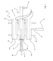
Fig. 1 eine bevorzugte Ausführungsform der Pressenanordnung in Draufsicht. - Die in
Fig. 1 dargestellte Pressenanordnung 10 umfasst insgesamt drei Pressenräume 11, die bewegbar angeordnet sind.Die Pressenräume 11 sind zu einem Zentralelement der Pressenordnung 10 zusammengefasst, fest miteinander verbunden und werden zusammen bewegt. DieBewegung der Pressenräume 11 erfolgt senkrecht zu ihrer Längsrichtung, also quer zur hier von links nach rechts verlaufenden Transferrichtung.Die Pressenräume 11 sind dabei auf Gleise 20 aufgesetzt, die die Bewegungsrichtung festlegen. ZurBewegung der Pressenräume 11 weist diePressenanordnung 10 derFig. 1 einen Linearantrieb inForm eines Elektromotors 12mit Spindeltrieb 18 auf, der aufgrund seiner Leistung in der Lage ist, diedrei Pressenräume 11 zu verschieben.Durch den Spindeltrieb 18 ist ein gut beherrschbares Anfahren und Abbremsen in einem engen Toleranzbereich möglich.Die Pressenanordnung 10 umfasst auf der inFig. 1 linken Seite zusätzlich eine ortsfest angeordnete Zuführvorrichtung 13, dieFörderelemente 14, im Ausführungsbeispiel derFig. 1 einen Gurtförderer, zum Einführen der Holzstapel 15 in den jeweils andie Zuführvorrichtung 13 angekoppelten Pressenraum 11 aufweist. Dem Pressenraum 11 vorgelagert ist einmit der Zuführvorrichtung 13verbundener Rahmen 16 zur Ausrichtung der Holzstapel 15 vor dem Pressen.Die Pressenräume 11 weisen ebenfalls Förderelemente 14 zum Transfer der Holzstapel 15 inden Pressenraum 11 und zum Ausfördern der fertig verpressten Werkstücke (inFig. 1 nicht dargestellt) zurAusführvorrichtung 17.Die Förderelemente 14, im Ausführungsbeispiel derFig. 1 als Rollengang ausgebildet, verfügen jeweils über einen eigenen Antrieb 19, der beim Ankoppeln der Zuführvorrichtung 13 anden Pressenraum 11 mitdem entsprechenden Antrieb 19der Förderelemente 14der Zuführvorrichtung 13 automatisch synchronisiert wird.Die Ausführvorrichtung 17 ist im Ausführungsbeispiel derFig. 1 auf der rechten Seite der Pressenräume 11 angeordnet, sodass hier eine Be- bzw.Entladung der Pressenräume 11 an den jeweils gegenüberliegenden Stirnseiten 21a,b der Pressenräume 11 erfolgt.
-
Fig. 1 a preferred embodiment of the press arrangement in plan view. - In the
Fig. 1 shownpress assembly 10 comprises a total of threepress rooms 11, which are arranged to be movable. Thepress rooms 11 are combined to form a central element of thepress order 10, firmly connected to each other and moved together. The movement of thepress chambers 11 takes place perpendicular to its longitudinal direction, ie transversely to the here from left to right extending transfer direction. Thepress rooms 11 are placed ontracks 20, which determine the direction of movement. To move thepress chambers 11, thepress assembly 10 of theFig. 1 a linear drive in the form of anelectric motor 12 withspindle drive 18, which is due to its power in a position to move the threepress rooms 11. By the spindle drive 18 a well controllable start and deceleration in a narrow tolerance range is possible. Thepress assembly 10 comprises on the inFig. 1 left side additionally a stationary arrangedfeed device 13, the conveyingelements 14, in the embodiment ofFig. 1 a belt conveyor, for introducing thewood stack 15 in each coupled to thefeeder 13press room 11 has. - The
press room 11 is preceded by a connected to thefeeder 13frame 16 for aligning thewood stack 15 before pressing. Thepress rooms 11 also have conveyingelements 14 for transferring the wood stacks 15 into thepress room 11 and for discharging the finished pressed workpieces (in FIGFig. 1 not shown) to theAusführvorrichtung 17. The conveyingelements 14, in the embodiment ofFig. 1 designed as a roller conveyor, each have theirown drive 19, which is automatically synchronized when coupling thesupply device 13 to thepress room 11 with the correspondingdrive 19 of theconveyor elements 14 of thefeeder 13. Theexpander 17 is in the embodiment ofFig. 1 arranged on the right side of thepress rooms 11, so that there is a loading or unloading of thepress rooms 11 at the respective opposite end faces 21a, b of thepress rooms 11.
Denkbar ist allerdings auch eine parallele Anordnung der Zuführvorrichtung 13 und der Ausführvorrichtung 17 auf einer der Stirnseiten 21 a,b der Pressenräume 11, sodass der zu entladende Pressenraum 11 jeweils vor die Ausführvorrichtung 17 verfahren wird. Der zu entladende Pressenraum 11 ist dabei so weit vom nächsten zu beladenden Pressenraum 11 beabstandet, dass simultan mit der Entladung des einen Pressenraumes 11 die Beladung des nächsten erfolgen kann. Auch die Ausführvorrichtung 17 weist entsprechende Förderelemente 14 auf, deren Antrieb 19 mit den Antrieben 19 der Förderelemente 14 der Pressenräume 11 und der Zuführvorrichtung 13 synchronisierbar ist. Durch die gezeigte Anordnung von Zuführvorrichtung 13, Pressenräumen 11 und Ausführvorrichtung 17 kann ein Holzstapel 15 bzw. ein fertiges Werkstück in Transferrichtung ohne Umlenken und/oder Richtungswechsel durch alle Produktionsstationen transportiert werden, wodurch eine nicht unerhebliche Reduzierung der Taktzeiten bei der Leimbinderherstellung einhergeht, die neben Kapazitätssteigerungen auch zu Kosteneinsparungen aufgrund besserer Anlagenauslastung führt. Diese Vorteile gelten auch für das angegebene Verfahren, das bevorzugt die vorstehend beschriebene Pressenanordnung verwendet.It is also conceivable, however, a parallel arrangement of the
- 1010
- = Pressenanordnung= Press arrangement
- 1111
- = Pressenraum= Press room
- 1212
- = Elektromotor= Electric motor
- 1313
- = Zuführvorrichtung= Feeder
- 1414
- = Förderelemente= Conveying elements
- 1515
- = Holzstapel= Woodpile
- 1616
- = Rahmen= Frame
- 1717
- = Ausführvorrichtung= Expander
- 1818
- = Spindeltrieb= Spindle drive
- 1919
- = Antrieb= Drive
- 2020
- = Gleis= Track
- 21a, b21a, b
- = Stirnseite= Front side
Claims (15)
dadurch gekennzeichnet, dass
characterized in that
dadurch gekennzeichnet, dass wenigstens eine Zuführvorrichtung (13) und wenigstens eine Ausführvorrichtung (17) jeweils an gegenüberliegenden Stirnseiten (21 a, 21 b) der Pressenräume (11) angeordnet sind.Press arrangement (10) according to claim 1,
characterized in that at least one feed device (13) and at least one delivery device (17) are respectively arranged on opposite end faces (21 a, 21 b) of the press spaces (11).
dadurch gekennzeichnet, dass die Pressenräume (11) parallel angeordnet sind.Press arrangement (10) according to claim 1 or 2,
characterized in that the press rooms (11) are arranged in parallel.
dadurch gekennzeichnet, dass die Zuführvorrichtung (13), die Pressenräume (11) und die Ausführvorrichtung (17) synchronisierbare Förderelemente (14) aufweisen.Press arrangement (10) according to one of the preceding claims,
characterized in that the feed device (13), the press chambers (11) and the delivery device (17) have synchronizable conveying elements (14).
dadurch gekennzeichnet, dass die Förderelemente (14) einen gemeinsamen Antrieb (19) aufweisen.Press arrangement (10) according to claim 4,
characterized in that the conveying elements (14) have a common drive (19).
dadurch gekennzeichnet, dass die Zuführvorrichtung (13) wenigstens ein Rahmenelement (16) für die Ausrichtung der Holz- oder Werkstoffstapel (15) aufweist.Press arrangement (10) according to one of the preceding claims,
characterized in that the feeding device (13) has at least one frame element (16) for the alignment of the wood or material stacks (15).
dadurch gekennzeichnet, dass die Zuführvorrichtung (13) und die Ausführvorrichtung (17) stationär und die Pressenräume (11) bewegbar angeordnet sind.Press arrangement (10) according to one of claims 1 to 6,
characterized in that the delivery device (13) and the delivery device (17) are stationary and the press spaces (11) are arranged to be movable.
dadurch gekennzeichnet, dass die Pressenräume (11) und/oder die Zuführvorrichtung (13) und/oder die Ausführvorrichtung (17) frei und/oder geführt, insbesondere gleisgebunden bewegbar sind.Press arrangement (10) according to one of the preceding claims,
characterized in that the press rooms (11) and / or the feed device (13) and / or the delivery device (17) are free and / or guided, in particular, can be moved in a track-bound manner.
dadurch gekennzeichnet, dass die Pressenräume (11), die Zuführvorrichtung (13) und/oder die Ausführvorrichtung (17) eine manuelle und/oder automatische Steuervorrichtung für die Bewegungen aufweisen.Press arrangement (10) according to claim 8,
characterized in that the press rooms (11), the feed device (13) and / or the delivery device (17) have a manual and / or automatic control device for the movements.
dadurch gekennzeichnet, dass die Pressenräume (11), die Zuführvorrichtung (13) und die Ausführvorrichtung (17) einen zentralen Antrieb (19) aufweisen.Press arrangement (10) according to one of claims 7 to 9,
characterized in that the press rooms (11), the feed device (13) and the delivery device (17) have a central drive (19).
dadurch gekennzeichnet, dass die Pressenräume (11) und die Zuführvorrichtung (13) und/oder die Ausführvorrichtung (17) getrennte Antriebe (19) aufweisen.Press arrangement (10) according to claim 7 to 9,
characterized in that the press rooms (11) and the feed device (13) and / or the delivery device (17) have separate drives (19).
dadurch gekennzeichnet, dass Positionierhilfen für die Pressenräume (11), die Zuführvorrichtung (13) und/oder die Ausführvorrichtung (17), insbesondere variable Anschlagkeile vorgesehen sind.Press arrangement (10) according to one of the preceding claims,
characterized in that positioning aids for the press rooms (11), the feed device (13) and / or the delivery device (17), in particular variable stop wedges are provided.
dadurch gekennzeichnet, dass die Zuführvorrichtung (13) und die Ausführvorrichtung (17) Erfassungsmittel für die Parameter der Holz- oder Werkstoffstapel (15) und des Leimbinders aufweisen.Press arrangement (10) according to one of the preceding claims,
characterized in that the feeding device (13) and the feeding device (17) comprise detecting means for the parameters of the wood or material stacks (15) and the glue binder.
dadurch gekennzeichnet, dass eine Speicher- und/oder Auswerteeinheit für die ermittelten Parameter vorgesehen ist.Press arrangement (10) according to claim 13,
characterized in that a storage and / or evaluation unit is provided for the determined parameters.
Applications Claiming Priority (1)
| Application Number | Priority Date | Filing Date | Title |
|---|---|---|---|
| DE202007011325U DE202007011325U1 (en) | 2007-08-13 | 2007-08-13 | Press arrangement |
Publications (3)
| Publication Number | Publication Date |
|---|---|
| EP2025481A2 true EP2025481A2 (en) | 2009-02-18 |
| EP2025481A3 EP2025481A3 (en) | 2010-02-17 |
| EP2025481B1 EP2025481B1 (en) | 2013-05-15 |
Family
ID=39777898
Family Applications (1)
| Application Number | Title | Priority Date | Filing Date |
|---|---|---|---|
| EP20080014262 Not-in-force EP2025481B1 (en) | 2007-08-13 | 2008-08-11 | Press device and method for producing laminated timber |
Country Status (2)
| Country | Link |
|---|---|
| EP (1) | EP2025481B1 (en) |
| DE (1) | DE202007011325U1 (en) |
Cited By (6)
| Publication number | Priority date | Publication date | Assignee | Title |
|---|---|---|---|---|
| WO2012016066A3 (en) * | 2010-07-28 | 2012-03-22 | Masonite Corporation | Automated door assembly, press, and adhesive therefor |
| US8991462B2 (en) | 2003-09-16 | 2015-03-31 | Masonite Corporation | Automated door assembly system and method |
| US9314983B2 (en) | 2010-07-28 | 2016-04-19 | Masonite Corporation | Automated door assembly, press, and adhesive therefor |
| US9511573B2 (en) | 2013-07-25 | 2016-12-06 | Masonite Corporation | Automated door assembly, press, and adhesive therefor |
| US9579818B2 (en) | 2013-03-15 | 2017-02-28 | Masonite Corporation | Automated door assembly and methods, press used therewith, and adhesive therefor |
| EP3038803A4 (en) * | 2013-08-27 | 2017-07-05 | Välinge Innovation AB | A method for producing a lamella core |
Citations (1)
| Publication number | Priority date | Publication date | Assignee | Title |
|---|---|---|---|---|
| DE10224793C1 (en) | 2002-06-04 | 2003-07-31 | Franz Binder Ges Mbh Holzindus | Laminated wood product manufacturing plant has laminated product fed to clock-controlled press or continuous press operated in parallel |
Family Cites Families (13)
| Publication number | Priority date | Publication date | Assignee | Title |
|---|---|---|---|---|
| DE1083034B (en) * | 1957-11-30 | 1960-06-09 | Eugen Siempelkamp | Multi-layer press with loading and unloading device |
| DE1653342A1 (en) * | 1966-10-26 | 1970-03-19 | Zagelow Dipl Ing Guenther | System for pressing chipboard or similar panels |
| DE2733765A1 (en) * | 1977-07-27 | 1979-02-15 | Buerkle Gmbh & Co Robert | High rate woodworking press assembly - consists of several presses displaced ensuring rapid loading and unloading |
| IT1137024B (en) * | 1981-05-22 | 1986-09-03 | Pagnoni Spa | LOADING AND UNLOADING EQUIPMENT OF A TWO-ROOM PRESS FOR THE PRODUCTION OF FIBROUS WOOD PANELS OR ITS SUBSTITUTES AND PROCEDURE FOR ITS OPERATION |
| DE3120920A1 (en) * | 1981-05-26 | 1982-12-16 | Maweg Dipl.-Ing. S. Knüpfer Maschinenfabrik GmbH & Co KG, 7303 Neuhausen | Press for producing beams or sheets from rods |
| US4776919A (en) * | 1986-01-24 | 1988-10-11 | Trus Joist Corporation | Laminated lumber press apparatus |
| DE3610287C2 (en) * | 1986-03-26 | 1996-02-08 | Alfred Meeth | Device for laminating and gluing wooden parts |
| DE8806883U1 (en) * | 1988-05-26 | 1988-10-20 | Wild, Herbert, 4831 Langenberg, De | |
| JPH03205A (en) * | 1989-05-26 | 1991-01-07 | Norin Suisansyo Shinrin Sogo Kenkyusho | High speed bonding method of wood by heating surface |
| US5470428A (en) * | 1993-06-24 | 1995-11-28 | Alfred D. Lobo Co., L.P.A. | Flow-through linear transfer system for making credit cards and the like, from synthetic resinous sheets |
| DK95096A (en) * | 1996-09-04 | 1998-03-05 | Kallesoee A S | Plant and method of laminating pressing |
| DE19835988B4 (en) * | 1997-05-03 | 2015-10-08 | Dieffenbacher GmbH Maschinen- und Anlagenbau | Method and plant for the production of wood-based panels or laminated veneer sheets |
| FI117128B (en) * | 2003-04-14 | 2006-06-30 | Vesme Systems Oy | Method of placing in a glue press a glue beam e.d. to be made and glue press |
-
2007
- 2007-08-13 DE DE202007011325U patent/DE202007011325U1/en not_active Expired - Lifetime
-
2008
- 2008-08-11 EP EP20080014262 patent/EP2025481B1/en not_active Not-in-force
Patent Citations (1)
| Publication number | Priority date | Publication date | Assignee | Title |
|---|---|---|---|---|
| DE10224793C1 (en) | 2002-06-04 | 2003-07-31 | Franz Binder Ges Mbh Holzindus | Laminated wood product manufacturing plant has laminated product fed to clock-controlled press or continuous press operated in parallel |
Cited By (13)
| Publication number | Priority date | Publication date | Assignee | Title |
|---|---|---|---|---|
| US9555609B2 (en) | 2003-09-16 | 2017-01-31 | Masonite Corporation | Automated door assembly system and method |
| US8991462B2 (en) | 2003-09-16 | 2015-03-31 | Masonite Corporation | Automated door assembly system and method |
| US10279574B2 (en) | 2003-09-16 | 2019-05-07 | Masonite Corporation | Automated door assembly system and method |
| US10232599B2 (en) | 2010-07-28 | 2019-03-19 | Masonite Corporation | Automated door assembly and methods, press used therewith, and adhesive therefor |
| US9346185B2 (en) | 2010-07-28 | 2016-05-24 | Masonite Corporation | Automated door assembly, press, and adhesive therefor |
| US10144147B2 (en) | 2010-07-28 | 2018-12-04 | Masonite Corporation | Automated door assembly, press, and adhesive therefor |
| WO2012016066A3 (en) * | 2010-07-28 | 2012-03-22 | Masonite Corporation | Automated door assembly, press, and adhesive therefor |
| US9314983B2 (en) | 2010-07-28 | 2016-04-19 | Masonite Corporation | Automated door assembly, press, and adhesive therefor |
| US10315334B2 (en) | 2010-07-28 | 2019-06-11 | Masonite Corporation | Automated door assembly, press, and adhesive therefor |
| US9579818B2 (en) | 2013-03-15 | 2017-02-28 | Masonite Corporation | Automated door assembly and methods, press used therewith, and adhesive therefor |
| US9511573B2 (en) | 2013-07-25 | 2016-12-06 | Masonite Corporation | Automated door assembly, press, and adhesive therefor |
| US10427393B2 (en) | 2013-07-25 | 2019-10-01 | Masonite Corporation | Automated door assembly, press, and adhesive therefor |
| EP3038803A4 (en) * | 2013-08-27 | 2017-07-05 | Välinge Innovation AB | A method for producing a lamella core |
Also Published As
| Publication number | Publication date |
|---|---|
| DE202007011325U1 (en) | 2008-09-25 |
| EP2025481B1 (en) | 2013-05-15 |
| EP2025481A3 (en) | 2010-02-17 |
Similar Documents
| Publication | Publication Date | Title |
|---|---|---|
| EP2025481B1 (en) | Press device and method for producing laminated timber | |
| EP2243619B1 (en) | Device and method for coating workpieces | |
| EP1792723B1 (en) | Method and device for producing a lightweight building slab | |
| EP0512503B1 (en) | Finger jointing press and combined finger jointing milling, gluing and press installation | |
| DE4035423A1 (en) | ENERGY- SPACE- AND COST-SAVING METHOD FOR THE PRODUCTION OF ENDLESS WOODS THROUGH WEDGE-JOINTING TO GLUE-PLATED WOODEN CARRIERS AND OTHER WOODEN PRODUCTS THAT, TOO WELL, TOO WELL, TOO WELL | |
| EP2025483B1 (en) | Press | |
| WO2005087464A1 (en) | Method and device for joining a sandwich plate batten frame | |
| EP3045278B1 (en) | Method for manufacturing panels and/or blocks made of wood | |
| AT400691B (en) | PRODUCTION PLANT FOR THE PRODUCTION OF A RAW PROFILE FROM ROD OR BOARD SHAPED SLATS | |
| DE10224793C1 (en) | Laminated wood product manufacturing plant has laminated product fed to clock-controlled press or continuous press operated in parallel | |
| EP2618972A1 (en) | Method for producing flat panel elements and device for carrying out such a method | |
| DE4421786C1 (en) | Method and device for producing a top layer for finished parquet | |
| DE102009021365A1 (en) | Method for producing veneer pack from layer of veneer for pressing pack in press during production of laminated veneer lumber, involves pulling out arms, and placing veneer on stack device for formation of veneer pack | |
| EP3208060B1 (en) | Method and device for manufacturing glued laminated timber | |
| DE102009021364A1 (en) | Method for producing veneer package during manufacturing laminated veneer lumber, involves moving veneer package to storage device in movement direction, where movement direction is directed against movement of laying device | |
| DE102009021368A1 (en) | Method for manufacturing laminate veneer lumber in press, involves guiding glued veneer to transport belts by two deposit stations, where veneer packets transfer storage device through piling device | |
| DE202007015954U1 (en) | Wood processing plant | |
| DE202015100323U1 (en) | Device for mounting an RFID tag | |
| WO2005009702A1 (en) | Method and device for producing wood-based panels | |
| WO2006015634A1 (en) | Device for drawing in veneer strips | |
| DE102023101981A1 (en) | Finger jointing line and connecting station for finger jointing line | |
| WO1997044168A1 (en) | Wooden blank, method of manufacturing it, and facility for implementing the method | |
| DE102021107909A1 (en) | Processing device for processing board or beam blanks and for gluing lamellas or lamella strands and method for this | |
| DE10027312A1 (en) | Fabrication method for glued laminated timbers and similar timber products heat energy required for drying is used to accelerate setting of glue | |
| DE10033155C1 (en) | Method and device for producing wooden components glued together from individual parts |
Legal Events
| Date | Code | Title | Description |
|---|---|---|---|
| PUAI | Public reference made under article 153(3) epc to a published international application that has entered the european phase |
Free format text: ORIGINAL CODE: 0009012 |
|
| AK | Designated contracting states |
Kind code of ref document: A2 Designated state(s): AT BE BG CH CY CZ DE DK EE ES FI FR GB GR HR HU IE IS IT LI LT LU LV MC MT NL NO PL PT RO SE SI SK TR |
|
| AX | Request for extension of the european patent |
Extension state: AL BA MK RS |
|
| PUAL | Search report despatched |
Free format text: ORIGINAL CODE: 0009013 |
|
| AK | Designated contracting states |
Kind code of ref document: A3 Designated state(s): AT BE BG CH CY CZ DE DK EE ES FI FR GB GR HR HU IE IS IT LI LT LU LV MC MT NL NO PL PT RO SE SI SK TR |
|
| AX | Request for extension of the european patent |
Extension state: AL BA MK RS |
|
| 17P | Request for examination filed |
Effective date: 20100817 |
|
| 17Q | First examination report despatched |
Effective date: 20100923 |
|
| AKX | Designation fees paid |
Designated state(s): AT BE BG CH CY CZ DE DK EE ES FI FR GB GR HR HU IE IS IT LI LT LU LV MC MT NL NO PL PT RO SE SI SK TR |
|
| RIC1 | Information provided on ipc code assigned before grant |
Ipc: B27D 3/02 20060101AFI20120402BHEP Ipc: B30B 15/30 20060101ALI20120402BHEP Ipc: B27M 3/00 20060101ALI20120402BHEP Ipc: B30B 7/02 20060101ALI20120402BHEP |
|
| GRAP | Despatch of communication of intention to grant a patent |
Free format text: ORIGINAL CODE: EPIDOSNIGR1 |
|
| GRAS | Grant fee paid |
Free format text: ORIGINAL CODE: EPIDOSNIGR3 |
|
| GRAA | (expected) grant |
Free format text: ORIGINAL CODE: 0009210 |
|
| AK | Designated contracting states |
Kind code of ref document: B1 Designated state(s): AT BE BG CH CY CZ DE DK EE ES FI FR GB GR HR HU IE IS IT LI LT LU LV MC MT NL NO PL PT RO SE SI SK TR |
|
| REG | Reference to a national code |
Ref country code: CH Ref legal event code: EP Ref country code: GB Ref legal event code: FG4D Free format text: NOT ENGLISH |
|
| REG | Reference to a national code |
Ref country code: AT Ref legal event code: REF Ref document number: 611885 Country of ref document: AT Kind code of ref document: T Effective date: 20130615 |
|
| REG | Reference to a national code |
Ref country code: IE Ref legal event code: FG4D Free format text: LANGUAGE OF EP DOCUMENT: GERMAN |
|
| REG | Reference to a national code |
Ref country code: DE Ref legal event code: R096 Ref document number: 502008009892 Country of ref document: DE Effective date: 20130711 |
|
| REG | Reference to a national code |
Ref country code: LT Ref legal event code: MG4D |
|
| REG | Reference to a national code |
Ref country code: NL Ref legal event code: VDEP Effective date: 20130515 |
|
| PG25 | Lapsed in a contracting state [announced via postgrant information from national office to epo] |
Ref country code: GR Free format text: LAPSE BECAUSE OF FAILURE TO SUBMIT A TRANSLATION OF THE DESCRIPTION OR TO PAY THE FEE WITHIN THE PRESCRIBED TIME-LIMIT Effective date: 20130816 Ref country code: SE Free format text: LAPSE BECAUSE OF FAILURE TO SUBMIT A TRANSLATION OF THE DESCRIPTION OR TO PAY THE FEE WITHIN THE PRESCRIBED TIME-LIMIT Effective date: 20130515 Ref country code: NO Free format text: LAPSE BECAUSE OF FAILURE TO SUBMIT A TRANSLATION OF THE DESCRIPTION OR TO PAY THE FEE WITHIN THE PRESCRIBED TIME-LIMIT Effective date: 20130815 Ref country code: ES Free format text: LAPSE BECAUSE OF FAILURE TO SUBMIT A TRANSLATION OF THE DESCRIPTION OR TO PAY THE FEE WITHIN THE PRESCRIBED TIME-LIMIT Effective date: 20130826 Ref country code: PT Free format text: LAPSE BECAUSE OF FAILURE TO SUBMIT A TRANSLATION OF THE DESCRIPTION OR TO PAY THE FEE WITHIN THE PRESCRIBED TIME-LIMIT Effective date: 20130916 Ref country code: LT Free format text: LAPSE BECAUSE OF FAILURE TO SUBMIT A TRANSLATION OF THE DESCRIPTION OR TO PAY THE FEE WITHIN THE PRESCRIBED TIME-LIMIT Effective date: 20130515 Ref country code: SI Free format text: LAPSE BECAUSE OF FAILURE TO SUBMIT A TRANSLATION OF THE DESCRIPTION OR TO PAY THE FEE WITHIN THE PRESCRIBED TIME-LIMIT Effective date: 20130515 Ref country code: IS Free format text: LAPSE BECAUSE OF FAILURE TO SUBMIT A TRANSLATION OF THE DESCRIPTION OR TO PAY THE FEE WITHIN THE PRESCRIBED TIME-LIMIT Effective date: 20130915 Ref country code: FI Free format text: LAPSE BECAUSE OF FAILURE TO SUBMIT A TRANSLATION OF THE DESCRIPTION OR TO PAY THE FEE WITHIN THE PRESCRIBED TIME-LIMIT Effective date: 20130515 |
|
| PG25 | Lapsed in a contracting state [announced via postgrant information from national office to epo] |
Ref country code: HR Free format text: LAPSE BECAUSE OF FAILURE TO SUBMIT A TRANSLATION OF THE DESCRIPTION OR TO PAY THE FEE WITHIN THE PRESCRIBED TIME-LIMIT Effective date: 20130515 Ref country code: BG Free format text: LAPSE BECAUSE OF FAILURE TO SUBMIT A TRANSLATION OF THE DESCRIPTION OR TO PAY THE FEE WITHIN THE PRESCRIBED TIME-LIMIT Effective date: 20130815 Ref country code: PL Free format text: LAPSE BECAUSE OF FAILURE TO SUBMIT A TRANSLATION OF THE DESCRIPTION OR TO PAY THE FEE WITHIN THE PRESCRIBED TIME-LIMIT Effective date: 20130515 |
|
| PGFP | Annual fee paid to national office [announced via postgrant information from national office to epo] |
Ref country code: GB Payment date: 20130816 Year of fee payment: 6 |
|
| PG25 | Lapsed in a contracting state [announced via postgrant information from national office to epo] |
Ref country code: LV Free format text: LAPSE BECAUSE OF FAILURE TO SUBMIT A TRANSLATION OF THE DESCRIPTION OR TO PAY THE FEE WITHIN THE PRESCRIBED TIME-LIMIT Effective date: 20130515 |
|
| PG25 | Lapsed in a contracting state [announced via postgrant information from national office to epo] |
Ref country code: CZ Free format text: LAPSE BECAUSE OF FAILURE TO SUBMIT A TRANSLATION OF THE DESCRIPTION OR TO PAY THE FEE WITHIN THE PRESCRIBED TIME-LIMIT Effective date: 20130515 Ref country code: DK Free format text: LAPSE BECAUSE OF FAILURE TO SUBMIT A TRANSLATION OF THE DESCRIPTION OR TO PAY THE FEE WITHIN THE PRESCRIBED TIME-LIMIT Effective date: 20130515 Ref country code: EE Free format text: LAPSE BECAUSE OF FAILURE TO SUBMIT A TRANSLATION OF THE DESCRIPTION OR TO PAY THE FEE WITHIN THE PRESCRIBED TIME-LIMIT Effective date: 20130515 Ref country code: SK Free format text: LAPSE BECAUSE OF FAILURE TO SUBMIT A TRANSLATION OF THE DESCRIPTION OR TO PAY THE FEE WITHIN THE PRESCRIBED TIME-LIMIT Effective date: 20130515 |
|
| PLBI | Opposition filed |
Free format text: ORIGINAL CODE: 0009260 |
|
| BERE | Be: lapsed |
Owner name: H.I.T. MASCHINENBAU G.M.B.H. + CO. KG Effective date: 20130831 |
|
| PG25 | Lapsed in a contracting state [announced via postgrant information from national office to epo] |
Ref country code: IT Free format text: LAPSE BECAUSE OF FAILURE TO SUBMIT A TRANSLATION OF THE DESCRIPTION OR TO PAY THE FEE WITHIN THE PRESCRIBED TIME-LIMIT Effective date: 20130515 Ref country code: NL Free format text: LAPSE BECAUSE OF FAILURE TO SUBMIT A TRANSLATION OF THE DESCRIPTION OR TO PAY THE FEE WITHIN THE PRESCRIBED TIME-LIMIT Effective date: 20130515 Ref country code: RO Free format text: LAPSE BECAUSE OF FAILURE TO SUBMIT A TRANSLATION OF THE DESCRIPTION OR TO PAY THE FEE WITHIN THE PRESCRIBED TIME-LIMIT Effective date: 20130515 |
|
| 26 | Opposition filed |
Opponent name: MINDA INDUSTRIEANLAGEN GMBH Effective date: 20140217 |
|
| PLAX | Notice of opposition and request to file observation + time limit sent |
Free format text: ORIGINAL CODE: EPIDOSNOBS2 |
|
| REG | Reference to a national code |
Ref country code: DE Ref legal event code: R026 Ref document number: 502008009892 Country of ref document: DE Effective date: 20140217 |
|
| REG | Reference to a national code |
Ref country code: IE Ref legal event code: MM4A |
|
| PG25 | Lapsed in a contracting state [announced via postgrant information from national office to epo] |
Ref country code: BE Free format text: LAPSE BECAUSE OF NON-PAYMENT OF DUE FEES Effective date: 20130831 |
|
| PG25 | Lapsed in a contracting state [announced via postgrant information from national office to epo] |
Ref country code: IE Free format text: LAPSE BECAUSE OF NON-PAYMENT OF DUE FEES Effective date: 20130811 |
|
| PLAF | Information modified related to communication of a notice of opposition and request to file observations + time limit |
Free format text: ORIGINAL CODE: EPIDOSCOBS2 |
|
| PLBB | Reply of patent proprietor to notice(s) of opposition received |
Free format text: ORIGINAL CODE: EPIDOSNOBS3 |
|
| GBPC | Gb: european patent ceased through non-payment of renewal fee |
Effective date: 20140811 |
|
| PG25 | Lapsed in a contracting state [announced via postgrant information from national office to epo] |
Ref country code: TR Free format text: LAPSE BECAUSE OF FAILURE TO SUBMIT A TRANSLATION OF THE DESCRIPTION OR TO PAY THE FEE WITHIN THE PRESCRIBED TIME-LIMIT Effective date: 20130515 Ref country code: CY Free format text: LAPSE BECAUSE OF FAILURE TO SUBMIT A TRANSLATION OF THE DESCRIPTION OR TO PAY THE FEE WITHIN THE PRESCRIBED TIME-LIMIT Effective date: 20130515 Ref country code: MT Free format text: LAPSE BECAUSE OF FAILURE TO SUBMIT A TRANSLATION OF THE DESCRIPTION OR TO PAY THE FEE WITHIN THE PRESCRIBED TIME-LIMIT Effective date: 20130515 |
|
| PG25 | Lapsed in a contracting state [announced via postgrant information from national office to epo] |
Ref country code: HU Free format text: LAPSE BECAUSE OF FAILURE TO SUBMIT A TRANSLATION OF THE DESCRIPTION OR TO PAY THE FEE WITHIN THE PRESCRIBED TIME-LIMIT; INVALID AB INITIO Effective date: 20080811 Ref country code: GB Free format text: LAPSE BECAUSE OF NON-PAYMENT OF DUE FEES Effective date: 20140811 Ref country code: LU Free format text: LAPSE BECAUSE OF NON-PAYMENT OF DUE FEES Effective date: 20130811 Ref country code: MC Free format text: LAPSE BECAUSE OF FAILURE TO SUBMIT A TRANSLATION OF THE DESCRIPTION OR TO PAY THE FEE WITHIN THE PRESCRIBED TIME-LIMIT Effective date: 20130515 |
|
| REG | Reference to a national code |
Ref country code: FR Ref legal event code: PLFP Year of fee payment: 8 |
|
| PGFP | Annual fee paid to national office [announced via postgrant information from national office to epo] |
Ref country code: CH Payment date: 20150929 Year of fee payment: 8 |
|
| PGFP | Annual fee paid to national office [announced via postgrant information from national office to epo] |
Ref country code: AT Payment date: 20150928 Year of fee payment: 8 Ref country code: FR Payment date: 20150923 Year of fee payment: 8 |
|
| PGFP | Annual fee paid to national office [announced via postgrant information from national office to epo] |
Ref country code: DE Payment date: 20151030 Year of fee payment: 8 |
|
| REG | Reference to a national code |
Ref country code: DE Ref legal event code: R119 Ref document number: 502008009892 Country of ref document: DE |
|
| REG | Reference to a national code |
Ref country code: CH Ref legal event code: PL |
|
| REG | Reference to a national code |
Ref country code: AT Ref legal event code: MM01 Ref document number: 611885 Country of ref document: AT Kind code of ref document: T Effective date: 20160811 |
|
| PG25 | Lapsed in a contracting state [announced via postgrant information from national office to epo] |
Ref country code: LI Free format text: LAPSE BECAUSE OF NON-PAYMENT OF DUE FEES Effective date: 20160831 Ref country code: CH Free format text: LAPSE BECAUSE OF NON-PAYMENT OF DUE FEES Effective date: 20160831 |
|
| REG | Reference to a national code |
Ref country code: FR Ref legal event code: ST Effective date: 20170428 |
|
| PG25 | Lapsed in a contracting state [announced via postgrant information from national office to epo] |
Ref country code: AT Free format text: LAPSE BECAUSE OF NON-PAYMENT OF DUE FEES Effective date: 20160811 |
|
| PG25 | Lapsed in a contracting state [announced via postgrant information from national office to epo] |
Ref country code: FR Free format text: LAPSE BECAUSE OF NON-PAYMENT OF DUE FEES Effective date: 20160831 Ref country code: DE Free format text: LAPSE BECAUSE OF NON-PAYMENT OF DUE FEES Effective date: 20170301 |
|
| PLBD | Termination of opposition procedure: decision despatched |
Free format text: ORIGINAL CODE: EPIDOSNOPC1 |
|
| REG | Reference to a national code |
Ref country code: DE Ref legal event code: R100 Ref document number: 502008009892 Country of ref document: DE |
|
| PLBM | Termination of opposition procedure: date of legal effect published |
Free format text: ORIGINAL CODE: 0009276 |
|
| STAA | Information on the status of an ep patent application or granted ep patent |
Free format text: STATUS: OPPOSITION PROCEDURE CLOSED |
|
| 27C | Opposition proceedings terminated |
Effective date: 20171006 |