EP2025278A1 - Vacuum cleaner filter bag - Google Patents
Vacuum cleaner filter bag Download PDFInfo
- Publication number
- EP2025278A1 EP2025278A1 EP07016207A EP07016207A EP2025278A1 EP 2025278 A1 EP2025278 A1 EP 2025278A1 EP 07016207 A EP07016207 A EP 07016207A EP 07016207 A EP07016207 A EP 07016207A EP 2025278 A1 EP2025278 A1 EP 2025278A1
- Authority
- EP
- European Patent Office
- Prior art keywords
- filter bag
- vacuum cleaner
- cleaner filter
- bag according
- inlet opening
- Prior art date
- Legal status (The legal status is an assumption and is not a legal conclusion. Google has not performed a legal analysis and makes no representation as to the accuracy of the status listed.)
- Granted
Links
Images
Classifications
-
- A—HUMAN NECESSITIES
- A47—FURNITURE; DOMESTIC ARTICLES OR APPLIANCES; COFFEE MILLS; SPICE MILLS; SUCTION CLEANERS IN GENERAL
- A47L—DOMESTIC WASHING OR CLEANING; SUCTION CLEANERS IN GENERAL
- A47L9/00—Details or accessories of suction cleaners, e.g. mechanical means for controlling the suction or for effecting pulsating action; Storing devices specially adapted to suction cleaners or parts thereof; Carrying-vehicles specially adapted for suction cleaners
- A47L9/10—Filters; Dust separators; Dust removal; Automatic exchange of filters
- A47L9/14—Bags or the like; Rigid filtering receptacles; Attachment of, or closures for, bags or receptacles
- A47L9/1427—Means for mounting or attaching bags or filtering receptacles in suction cleaners; Adapters
- A47L9/1436—Connecting plates, e.g. collars, end closures
- A47L9/1445—Connecting plates, e.g. collars, end closures with closure means
- A47L9/1454—Self-sealing closures, e.g. valves
Definitions
- the invention relates to a vacuum cleaner filter bag comprising an inlet opening, a filter bag material having an inner layer of nonwoven material at least in the region of the inlet opening, and a holding plate arranged on the filter bag outside in the region of the inlet opening and attachable to a holding device of a vacuum cleaner for holding the vacuum cleaner filter bag a closure device, in particular a closure flap, is provided for closing the inlet opening.
- Vacuum cleaner filter bags are placed inside the housing of a vacuum cleaner to pick up the sucked dust.
- vacuum cleaner filter bags For mounting the vacuum cleaner filter bag inside the housing, vacuum cleaner filter bags each comprise a holding plate, by way of which the vacuum cleaner filter bag can be fixed to a holding device provided in the interior of the housing.
- Such vacuum cleaner filter bags and holding plates have an inlet opening, through which an air flow with dust particles can enter the interior of the filter bag. For various reasons, it is desirable that this inlet opening be closed. On the one hand, it can be prevented by a closed inlet opening when disposing of a filled vacuum cleaner filter bag that emerges in the filter bag accumulated dust. Furthermore, some vacuum cleaner filter bags contain loose particles, for example for odor absorption. In order to prevent falling out of these particles, closing the inlet opening is likewise advantageous.
- the filter cake often protrudes into the pivotal region of the closure flap, so that when closing the flap, more or less material is clamped and thereby obstructing the closure function, i. the flap does not completely close the vacuum cleaner filter bag.
- the formation of the filter cake is in this case particularly strong in low-flow areas, for example in the region of the hinge of the flap to observe.
- a vacuum cleaner filter bag comprising an inlet opening, a filter bag material having an inner layer of nonwoven material at least in the region of the inlet opening, and a holding plate arranged on the filter bag outside in the region of the inlet opening, which can be attached to a holding device of a vacuum cleaner for holding the vacuum cleaner filter bag and in which a closure device is provided for closing the inlet opening, wherein the nonwoven material in the region of the inlet opening has a surface which is provided such that the formation of a filter cake on this surface is avoided.
- a surface of the nonwoven material on which no filter cake can form ie a free-lying surface, hereinafter also referred to as open space
- a free-lying surface hereinafter also referred to as open space
- the surface (free surface) can be completely or partially formed by a film, in particular a self-adhesive coated film. This is a particularly effective way to build to avoid a filter cake.
- the attachment of the film can be done for example by gluing (coated film) or welding.
- the surface (free surface) can be completely or partially formed by a paper, a cardboard or a cardboard, in particular a self-adhesive coated paper, a self-adhesive coated cardboard or a self-adhesive coated cardboard.
- a paper, a cardboard or a cardboard in particular a self-adhesive coated paper, a self-adhesive coated cardboard or a self-adhesive coated cardboard.
- the surface (free surface) may be completely or partially formed by compacted nonwoven material.
- the surface of the nonwoven fabric can be given a sheet-like character.
- This compacting can be done by ultrasonic welding or thermal welding. This provides another alternative.
- the surface (free surface) can be formed completely or partially by a liquid which dries during film formation. As a result, the nonwoven fabric is smoothed on the surface (free surface). This provides another alternative.
- the surface (free surface) may be in the form of a strip running around the inlet opening, preferably a ring.
- the circumferential strip may be open or closed, so that in the latter case, the inlet opening is completely surrounded by the strip (ring).
- Said strip or ring may be made different widths in a partial areas. As a result, it can be optimally adapted to the respective conditions.
- the strip may be annular, which offers a simple way of producing the vacuum cleaner filter bag according to the invention.
- the strip in the two alternatives mentioned above may have a width in the range of 5 mm to 150 mm, preferably 10 mm to 50 mm.
- the minimum width results from the typical extension of a filter cake of house dust beyond an edge.
- the maximum width is only limited by the fact that the loss of effective filter area should be kept as low as possible.
- a relatively large width may be necessary when the filler opening is seated close to an edge of the filter bag and the filter cake grows from the side surface into the pivotal region of the flap.
- the closure device may comprise a pivotable closure element, whereby an effective closure mechanism is provided.
- the closure element can be arranged in the filter bag interior in the region of the inlet opening.
- the above-mentioned film may continue to be useful as a sealing element between the filter bag and holding device of the vacuum cleaner, wherein the film may consist in particular of a thermoplastic elastomer.
- the film may additionally also be a sealing element to the stub out (sole or additional seal between the vacuum cleaner and filter bag).
- the vacuum cleaner filter bag according to the invention can also be the compacted nonwoven material as a sealing element between the filter bag and holding device of the vacuum cleaner be usable. In the two last developments, no separate seal is needed.
- said film may be antistatic, which additionally prevents deposition of fibers and dust on the surface (open space).
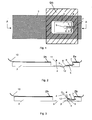
- FIG. 1 shows a schematic plan view (opposite to the opening direction) on a holding plate 2 of a vacuum cleaner filter bag according to the invention.
- This holding plate 2 is provided for example in the form of an injection molded part made of a plastic.
- an inlet opening 3 is provided, which is closed in the example shown by a closure element or a flap 4.
- Closure element 4 and retaining plate 2 are integrally formed as an injection molded part, wherein the closure element 4 is connected via a film hinge 5, through which a pivot axis is formed, with the holding plate 2.
- a spring element 6 is provided in the form of a leaf spring to hold the closure element 4 in the first position shown, the closure position.
- a longitudinal end 7 of the leaf spring 6 is connected by an embedding in the plastic fixed to the support plate 2.
- the other longitudinal end 8 is movable on the closure element 4 on.
- the leaf spring 6 is in the opening direction behind, in the plan view shown opposite to the opening direction, however, arranged in front of the closure element 4.
- a hole 9 is further provided, in which the leaf spring 6 engages upon pivoting of the closure element 4 in the opening direction.
- the leaf spring 6 is cambered, thus has transverse to the longitudinal axis on a continuous curvature. Due to this curvature, the leaf spring 6 touches the surface of the closure element 4 only at its longitudinal side edges.
- the nonwoven material not shown in this figure for the sake of clarity, has around the inlet opening 3 a provided with self-adhesive film surface 20, which prevents the construction of a filter cake on this surface.
- FIG. 2 is a schematic cross-sectional view through the retaining plate of FIG. 1 along the line AA, which runs along one of the longitudinal axes of the leaf spring 6.
- the one longitudinal end 7 of the leaf spring 6 is embedded in the plastic of the holding plate 2 and thus fixed.
- the other longitudinal end 8 touches in the region of the side edges of the leaf spring (the contact area) the closure element 4, so that is held at a suitably selected bias of the leaf spring, the closure element by the restoring force of the spring in the first position shown or closed position.
- the holding plate 2 is connected to the nonwoven fabric 10 of a vacuum cleaner filter bag, for example glued.
- the bag wall may also have fixedly connected fastening elements with which a retaining plate can then be detachably connected in a non-destructive manner, so that such a retaining plate can be reused several times.
- the bag wall may have a filter structure, as for example in the EP 0 960 645 is described.
- the nonwoven material 10 has around the inlet opening the self-adhesive film provided surface 20, which also in Fig. 1 is shown.
- the hole 9 is in the example shown in blind hole, the bottom 12 is formed by an elastic film. Such elastic cover of the hole 9 can thereby take place that a TPE (thermoplastic polymer) is sprayed in 2K process on this area of the closure element. Due to such a floor, dirt is prevented from leaking out of the bag interior through the hole.
- TPE thermoplastic polymer
- the closure element 4 is acted upon by a suction air flow with a force which acts counter to the restoring force of the leaf spring 6. If the force of the suction air flow exceeds the restoring force of the leaf spring, the closure element in the opening direction 11, see FIG. 2 , and thus pivoted in the direction of the interior of the filter bag around the pivot axis formed by the film hinge 5.
- the blind hole may also be formed by a depression in the closure element, so that the bottom is not elastic in the case of a stiff plastic.
- the hole 9 may instead be a continuous hole. The latter is particularly advantageous in a design with a hole in the holding plate and not in the closure element, since then the connection of the holding plate with the filter material of the bag wall can be selected such that the hole does not open into the interior of the bag (ie flows outside the bag wall) and thus no dirt can escape from the bag through this.
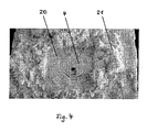
- FIG. 4 the photograph of a filter bag according to the invention is shown.
- the immediate vicinity 20 of the inlet opening, which is closed by the closure element 4, is free of filter cake 21.
- the surface 20 is realized by a film which substantially prevents the deposition of filtrate due to its smoothness and tightness.
Abstract
Description
Die Erfindung betrifft einen Staubsaugerfilterbeutel umfassend eine Einlassöffnung, ein Filterbeutelmaterial, das zumindest im Bereich der Einlassöffnung eine Innenlage aus Vliesmaterial aufweist, und eine an der Filterbeutelaußenseite im Bereich der Einlassöffnung angeordnete Halteplatte, die an einer Halteeinrichtung eines Staubsaugers zur Halterung des Staubsaugerfilterbeutels anbringbar ist und an der eine Verschlussvorrichtung, insbesondere eine Verschlussklappe, zum Verschließen der Einlassöffnung vorgesehen ist.The invention relates to a vacuum cleaner filter bag comprising an inlet opening, a filter bag material having an inner layer of nonwoven material at least in the region of the inlet opening, and a holding plate arranged on the filter bag outside in the region of the inlet opening and attachable to a holding device of a vacuum cleaner for holding the vacuum cleaner filter bag a closure device, in particular a closure flap, is provided for closing the inlet opening.
Staubsaugerfilterbeutel werden im Innern des Gehäuses eines Staubsaugers angeordnet, um den angesaugten Staub aufzunehmen. Zur Befestigung des Staubsaugerfilterbeutels im Innern des Gehäuses umfassen Staubsaugerfilterbeutel jeweils eine Halteplatte, über die der Staubsaugerfilterbeutel an einer im Innern des Gehäuses vorgesehenen Halteeinrichtung fixiert werden kann.Vacuum cleaner filter bags are placed inside the housing of a vacuum cleaner to pick up the sucked dust. For mounting the vacuum cleaner filter bag inside the housing, vacuum cleaner filter bags each comprise a holding plate, by way of which the vacuum cleaner filter bag can be fixed to a holding device provided in the interior of the housing.
Derartige Staubsaugerfilterbeutel und Halteplatten weisen eine Einlassöffnung auf, durch die ein Luftstrom mit Staubpartikeln in das Innere des Filterbeutels eintreten kann. Aus verschiedenen Gründen ist es wünschenswert, dass diese Einlassöffnung verschlossen werden kann. Zum einen kann durch eine verschlossene Einlassöffnung beim Entsorgen eines gefüllten Staubsaugerfilterbeutels verhindert werden, dass im Filterbeutel angesammelter Staub austritt. Weiterhin enthalten manche Staubsaugerfilterbeutel lose Partikel, beispielsweise zur Geruchsabsorption. Um ein Herausfallen dieser Partikel zu verhindern, ist ebenfalls ein Verschließen der Einlassöffnung von Vorteil.Such vacuum cleaner filter bags and holding plates have an inlet opening, through which an air flow with dust particles can enter the interior of the filter bag. For various reasons, it is desirable that this inlet opening be closed. On the one hand, it can be prevented by a closed inlet opening when disposing of a filled vacuum cleaner filter bag that emerges in the filter bag accumulated dust. Furthermore, some vacuum cleaner filter bags contain loose particles, for example for odor absorption. In order to prevent falling out of these particles, closing the inlet opening is likewise advantageous.
Als Materialien für Staubsaugerbeutel haben sich in den letzten Jahren Vliesstoffe durchgesetzt, die sich durch geringe Verstopfungsneigung und hohe Staubrückhaltung auszeichnen.As materials for vacuum cleaner bags nonwovens have become established in recent years, which are characterized by low tendency to clog and high dust retention.
Der Nachteil diese bekannten Staubsaugerfilterbeutel besteht darin, dass sich Hausstaub, der auch faserförmige Bestandteile, wie Teppichfasern und Haare enthält, auch im Bereich der Einlassöffnung als relativ fester Filterkuchen ablagert und dort die Verschlussfunktion der Halteplatte beeinträchtigen kann.The disadvantage of these known vacuum cleaner filter bags is that house dust, which also contains fibrous components, such as carpet fibers and hair, also deposits in the region of the inlet opening as a relatively firm filter cake and there may affect the sealing function of the retaining plate.
Insbesondere ragt der Filterkuchen oftmals in den Schwenkbereich der Verschlussklappe herein, so dass beim Schließen der Klappe mehr oder weniger viel Material eingeklemmt wird und dadurch die Verschlussfunktion behindert wird, d.h. die Verschlussklappe den Staubsaugerfilterbeutel nicht vollständig verschließt.In particular, the filter cake often protrudes into the pivotal region of the closure flap, so that when closing the flap, more or less material is clamped and thereby obstructing the closure function, i. the flap does not completely close the vacuum cleaner filter bag.
Die Ausbildung des Filterkuchens ist hierbei besonders stark in strömungsarmen Bereichen, beispielsweise im Bereich des Scharniers der Verschlussklappe, zu beobachten.The formation of the filter cake is in this case particularly strong in low-flow areas, for example in the region of the hinge of the flap to observe.
Angesichts dieses Standes der Technik ist es die Aufgabe der Erfindung, einen Staubsaugerfilterbeutel bereitzustellen, der sich durch eine verbesserte Verschlussfunktion auszeichnet.In view of this prior art, it is the object of the invention to provide a vacuum cleaner filter bag, which is characterized by an improved closure function.
Diese Aufgabe wird gelöst durch einen Staubsaugerfilterbeutel gemäß Anspruch 1.This object is achieved by a vacuum cleaner filter bag according to claim 1.
Erfindungsgemäß wird ein Staubsaugerfilterbeutel bereitgestellt, umfassend eine Einlassöffnung, ein Filterbeutelmaterial, das zumindest im Bereich der Einlassöffnung eine Innenlage aus Vliesmaterial aufweist, und eine an der Filterbeutelaußenseite im Bereich der Einlassöffnung angeordnete Halteplatte, die an einer Halteeinrichtung eines Staubsaugers zur Halterung des Staubsaugerfilterbeutels anbringbar ist und an der eine Verschlussvorrichtung zum Verschließen der Einlassöffnung vorgesehen ist, wobei das Vliesmaterial im Bereich der Einlassöffnung eine Fläche aufweist, welche derart vorgesehen ist, dass die Ausbildung eines Filterkuchens auf dieser Fläche vermieden wird.According to the invention, a vacuum cleaner filter bag is provided, comprising an inlet opening, a filter bag material having an inner layer of nonwoven material at least in the region of the inlet opening, and a holding plate arranged on the filter bag outside in the region of the inlet opening, which can be attached to a holding device of a vacuum cleaner for holding the vacuum cleaner filter bag and in which a closure device is provided for closing the inlet opening, wherein the nonwoven material in the region of the inlet opening has a surface which is provided such that the formation of a filter cake on this surface is avoided.
Das Vorsehen einer Fläche des Vliesmaterials, auf dem sich kein Filterkuchen ausbilden kann, also eine freibleibende Fläche, im folgenden auch als Freifläche bezeichnet, hat den Vorteil, dass sich keine größere Anzahl von Fasern in der Nähe der Einlassöffnung ablagern und somit die Ausbildung eines Filterkuchens in diesem Bereich verhindert wird. Der Staub ist somit nicht in der Lage, sich in der Oberfläche zu verkrallen (Formschluss) und somit Ansatzpunkte für den Aufbau eines Filterkuchens zu bilden. Als Ergebnis wird die Verschlussvorrichtung nicht durch einen Filterkuchen, der in den Bereich der Verschlussvorrichtung ragt, behindert.The provision of a surface of the nonwoven material on which no filter cake can form, ie a free-lying surface, hereinafter also referred to as open space, has the advantage that no larger number of fibers deposit in the vicinity of the inlet opening and thus the formation of a filter cake prevented in this area. The dust is therefore not able to dig into the surface (positive engagement) and thus forming starting points for the construction of a filter cake. As a result, the closure device is not obstructed by a filter cake protruding into the region of the closure device.
Bei dem erfindungsgemäßen Staubsaugerfilterbeutel kann die Fläche (Freifläche) vollständig oder teilweise durch eine Folie, insbesondere eine selbstklebend beschichtete Folie, ausgebildet sein. Dieses stellt eine besonders effektive Weise dar, um den Aufbau eines Filterkuchens zu vermeiden. Das Befestigen der Folie kann beispielsweise durch Kleben (beschichtete Folie) oder Schweißen erfolgen.In the vacuum cleaner filter bag according to the invention, the surface (free surface) can be completely or partially formed by a film, in particular a self-adhesive coated film. This is a particularly effective way to build to avoid a filter cake. The attachment of the film can be done for example by gluing (coated film) or welding.
Bei dem erfindungsgemäßen Staubsaugerfilterbeutel kann die Fläche (Freifläche) vollständig oder teilweise durch ein Papier, einen Karton oder eine Pappe, insbesondere ein selbstklebend beschichtetes Papier, einen selbstklebend beschichteten Karton oder eine selbstklebend beschichtete Pappe, ausgebildet sein. Durch die Verwendung von glattem Papier, Karton oder Pappe zur Bedeckung eines zur Einlassöffnung unmittelbar benachbarten Teils des Vliesstoffs wird eine Alternative zur Folie zur Verfügung gestellt.In the vacuum cleaner filter bag according to the invention, the surface (free surface) can be completely or partially formed by a paper, a cardboard or a cardboard, in particular a self-adhesive coated paper, a self-adhesive coated cardboard or a self-adhesive coated cardboard. By using plain paper, cardboard or paperboard to cover a portion of the nonwoven fabric immediately adjacent the inlet opening, an alternative to the film is provided.
Bei dem erfindungsgemäßen Staubsaugerfilterbeutel kann die Fläche (Freifläche) vollständig oder teilweise durch verdichtetes Vliesmaterial ausgebildet sein. Dadurch kann die Oberfläche des Vliesstoffs einen folienartigen Charakter erhalten. Dieses Verdichten kann durch Ultraschallschweißen oder thermisches Schweißen erfolgen. Dieses stellt eine andere Alternative zur Verfügung.In the vacuum cleaner filter bag according to the invention, the surface (free surface) may be completely or partially formed by compacted nonwoven material. Thereby, the surface of the nonwoven fabric can be given a sheet-like character. This compacting can be done by ultrasonic welding or thermal welding. This provides another alternative.
Bei dem erfindungsgemäßen Staubsaugerfilterbeutel kann die Fläche (Freifläche) vollständig oder teilweise durch eine unter Filmbildung abtrocknende Flüssigkeit ausgebildet sein. Dadurch wird der Vliesstoff auf der Fläche (Freifläche) geglättet. Dieses stellt eine weitere Alternative zur Verfügung.In the case of the vacuum cleaner filter bag according to the invention, the surface (free surface) can be formed completely or partially by a liquid which dries during film formation. As a result, the nonwoven fabric is smoothed on the surface (free surface). This provides another alternative.
Wenn mit einer der zuvor genannten Alternative allein kein ausreichender Effekt erzielt wird, können die Alternativen auch kombiniert werden. So ist es in vorteilhafter Weise möglich, zunächst den entsprechenden Bereich der Freifläche thermisch zu verdichten und dann noch mit einer Folie zu versehen.If one of the alternatives mentioned above alone does not achieve a sufficient effect, the alternatives can also be combined. Thus, it is advantageously possible to first thermally compress the corresponding area of the free surface and then to provide it with a film.
Bei dem erfindungsgemäßen Staubsaugerfilterbeutel kann die Fläche (Freifläche) in Form eines um die Einlassöffnung laufenden Streifens, vorzugsweise eines Rings ausgebildet sein. Dies hat den Vorteil, dass ein um die Einlassöffnung herum verlaufender Bereich frei von Filterkuchen gehalten wird. Dabei kann der umlaufende Streifen offen oder geschlossen sein, so dass im letzteren Fall die Einlassöffnung vollständig von dem Streifen umgeben ist (Ring).In the vacuum cleaner filter bag according to the invention, the surface (free surface) may be in the form of a strip running around the inlet opening, preferably a ring. This has the advantage that an area running around the inlet opening is kept free of filter cake. In this case, the circumferential strip may be open or closed, so that in the latter case, the inlet opening is completely surrounded by the strip (ring).
Der genannte Streifen oder Ring kann in einem Teilbereichen unterschiedlich breit ausgeführt sein. Dadurch kann er optimal an die jeweiligen Verhältnisse angepasst werden.Said strip or ring may be made different widths in a partial areas. As a result, it can be optimally adapted to the respective conditions.
So ist es sinnvoll den Streifen in der Nähe eines Verschlussklappenschamiers breiter auszubilden und in Bereichen in denen hohe Strömungsgeschwindigkeiten herrschen schmaler zu halten. Weil die Ablagerung von Filtrat in der Nähe der Einlassöffnung bevorzugt dort erfolgt, wo die Geschwindigkeit der Strömung gering ist, ist es von Vorteil, den Streifen dort breiter auszubilden. Dies erfolgt auch im Hinblick auf die möglichst effektive Nutzung der Filterbeutelfläche in der Weise, dass der Streifen nur so breit wie nötig ausgebildet wird, um ein Blockieren des Verschlusses zu verhindern, da in der Freifläche keine oder nur eine sehr geringe Filterung erfolgt.Thus, it makes sense to make the strip wider in the vicinity of a shutter flap hinge and narrow in areas where high flow velocities prevail. Because the deposition of filtrate in the vicinity of the inlet opening preferably occurs where the velocity of the flow is low, it is advantageous to make the strip wider there. This is also done with regard to the most effective use of the filter bag surface in such a way that the strip is formed only as wide as necessary to prevent blocking of the closure, since in the open space no or only a very low filtration.
Alternativ dazu kann der Streifen ringförmig ausgebildet sein, was eine einfache Möglichkeit zur Herstellung des erfindungsgemäßen Staubsaugerfilterbeutels bietet.Alternatively, the strip may be annular, which offers a simple way of producing the vacuum cleaner filter bag according to the invention.
Der Streifen in den beiden zuvor genannten Alternativen kann eine Breite im Bereich von 5 mm bis 150 mm, vorzugsweise 10 mm bis 50 mm, aufweisen. Die minimale Breite ergibt sich durch die typische Ausdehnung eines Filterkuchens aus Hausstaub über eine Kante hinaus. Die maximale Breite ist nur dadurch limitiert, dass der Verlust an wirksamer Filterfläche möglichst gering gehalten werden soll. Eine relativ große Breite kann dann notwendig sein, wenn die Einfüllöffnung nahe an einer Kante des Filterbeutels sitzt und der Filterkuchen von der Seitenfläche aus in den Schwenkbereich der Klappe hereinwächst.The strip in the two alternatives mentioned above may have a width in the range of 5 mm to 150 mm, preferably 10 mm to 50 mm. The minimum width results from the typical extension of a filter cake of house dust beyond an edge. The maximum width is only limited by the fact that the loss of effective filter area should be kept as low as possible. A relatively large width may be necessary when the filler opening is seated close to an edge of the filter bag and the filter cake grows from the side surface into the pivotal region of the flap.
Bei dem erfindungsgemäßen Staubsaugerfilterbeutel kann die Verschlussvorrichtung ein verschwenkbares Verschlusselement umfassen, wodurch ein wirkungsvoller Verschlussmechanismus zur Verfügung gestellt wird. Das Verschlusselement kann dabei im Filterbeutelinneren im Bereich der Einlassöffnung angeordnet sein.In the vacuum cleaner filter bag according to the invention, the closure device may comprise a pivotable closure element, whereby an effective closure mechanism is provided. The closure element can be arranged in the filter bag interior in the region of the inlet opening.
Bei dem erfindungsgemäßen Staubsaugerfilterbeutel kann die oben genannte Folie weiterhin als Dichtelement zwischen Filterbeutel und Halteeinrichtung des Staubsaugers nutzbar sein, wobei die Folie insbesondere aus einem thermoplastischen Elastomer bestehen kann. Somit kann die Folie zusätzlich auch noch ein Dichtelement zum Stutzen hin sein (alleinige oder zusätzliche Dichtung zwischen Staubsauger und Filterbeutel).In the vacuum cleaner filter bag according to the invention, the above-mentioned film may continue to be useful as a sealing element between the filter bag and holding device of the vacuum cleaner, wherein the film may consist in particular of a thermoplastic elastomer. Thus, the film may additionally also be a sealing element to the stub out (sole or additional seal between the vacuum cleaner and filter bag).
Bei dem erfindungsgemäßen Staubsaugerfilterbeutel kann auch das verdichtete Vliesmaterial als Dichtelement zwischen Filterbeutel und Halteeinrichtung des Staubsaugers nutzbar sein. In den beiden letzten Weiterbildungen wird somit keine separate Dichtung benötigt.In the vacuum cleaner filter bag according to the invention can also be the compacted nonwoven material as a sealing element between the filter bag and holding device of the vacuum cleaner be usable. In the two last developments, no separate seal is needed.
Bei dem erfindungsgemäßen Staubsaugerfilterbeutel kann die genannte Folie antistatisch ausgebildet sein, was zusätzlich eine Ablagerung von Fasern und Staub auf der Fläche (Freifläche) verhindert.In the vacuum cleaner filter bag according to the invention said film may be antistatic, which additionally prevents deposition of fibers and dust on the surface (open space).
Weitere Vorteile und Merkmale der Erfindung werden nachfolgend anhand der Figuren beispielhaft erläutert. Dabei zeigt
- Figur 1
- eine Draufsicht auf eine Halteplatte des erfindungsgemäßen Staubsaugerfilterbeutels mit geschlossener Einlassöffnung;
Figur 2- eine Querschnittsansicht der Halteplatte von
Figur 1 ; Figur 3- eine Querschnittsansicht einer Halteplatte mit geöffneter Einlassöffnung; und
Figur 4- eine fotografische Draufsicht auf einen erfindungsgemäßen Staubsaugerfilterbeutel mit Filterkuchen.
- FIG. 1
- a plan view of a holding plate of the vacuum cleaner filter bag according to the invention with closed inlet opening;
- FIG. 2
- a cross-sectional view of the holding plate of
FIG. 1 ; - FIG. 3
- a cross-sectional view of a holding plate with an opened inlet opening; and
- FIG. 4
- a photographic plan view of a vacuum cleaner filter bag according to the invention with filter cake.
Weiterhin ist ein Federelement 6 in Form einer Blattfeder vorgesehen, um das Verschlusselement 4 in der gezeigten ersten Stellung, der Verschlussstellung, zu halten. Ein Längsende 7 der Blattfeder 6 ist durch eine Einbettung in den Kunststoff fest mit der Halteplatte 2 verbunden. Das andere Längsende 8 liegt beweglich auf dem Verschlusselement 4 auf. Die Blattfeder 6 ist in Öffnungsrichtung hinter, in der gezeigten Draufsicht entgegen der Öffnungsrichtung dagegen vor dem Verschlusselement 4 angeordnet.Furthermore, a
Im Verschlusselement 4 ist weiterhin ein Loch 9 vorgesehen, in das die Blattfeder 6 bei einem Schwenken des Verschlusselements 4 in Öffnungsrichtung eingreift. Die Blattfeder 6 ist bombiert, weist also quer zur Längsachse eine durchgehende Wölbung auf. Aufgrund dieser Wölbung berührt die Blattfeder 6 die Oberfläche des Verschlusselements 4 nur an ihren längs verlaufenden Seitenkanten.In the
Das in dieser Figur der Übersichtlichkeit wegen nicht dargestellte Vliesmaterial weist um die Einlassöffnung 3 eine mit selbstklebender Folie versehene Fläche 20 auf, die den Aufbau eines Filterkuchens auf dieser Fläche verhindert.The nonwoven material not shown in this figure for the sake of clarity, has around the inlet opening 3 a provided with self-
Wie dieser Querschnittsansicht zu entnehmen ist, ist das eine Längsende 7 der Blattfeder 6 in den Kunststoff der Halteplatte 2 eingebettet und damit fixiert. Das andere Längsende 8 berührt im Bereich der Seitenkanten der Blattfeder (dem Kontaktbereich) das Verschlusselement 4, so dass bei einer geeignet gewählten Vorspannung der Blattfeder das Verschlusselement durch die Rückstellkraft der Feder in der gezeigten ersten Stellung oder Verschlussstellung gehalten wird.As this cross-sectional view can be seen, the one
Die Halteplatte 2 ist mit dem Vliesstoff 10 eines Staubsaugerfilterbeutels verbunden, beispielsweise verklebt. Alternativ kann die Beutelwand auch damit fest verbundene Befestigungselemente aufweisen, mit denen dann eine Halteplatte zerstörungsfrei lösbar verbunden werden kann, so dass eine derartige Halteplatte mehrfach verwendbar ist. Die Beutelwand kann eine Filterstruktur aufweisen, wie sie beispielsweise in der
Das Vliesmaterial 10 weist um die Einlassöffnung die mit selbstklebender Folie versehene Fläche 20 auf, die auch in
Das Loch 9 ist in dem gezeigten Beispiel in Sackloch, dessen Boden 12 durch eine elastische Folie gebildet wird. Eine solche elastische Abdeckung des Lochs 9 kann dadurch erfolgen, dass ein TPE (Thermoplastisches Polymer) im 2K-Verfahren auf diesen Bereich des Verschlusselements gespritzt wird. Aufgrund eines solchen Bodens wird verhindert, dass Schmutz durch das Loch aus dem Beutelinnern austritt.The
Im Betrieb des Staubsaugerfilterbeutels in einem Staubsaugergehäuse wird das Verschlusselement 4 durch einen Saugluftstrom mit einer Kraft beaufschlagt, die entgegen der Rückstellkraft der Blattfeder 6 wirkt. Übersteigt die Kraft des Saugluftstroms die Rückstellkraft der Blattfeder, wird das Verschlusselement in Öffnungsrichtung 11, siehe
Aufgrund dieser Schwenkbewegung verschiebt sich der Anlagebereich des Verschlusselements 4 entlang der Seitenkanten der Blattfeder 6 in Richtung des eingespannten Längsendes 7. Dies führt dazu, dass das andere Längsende 8 in das in dem Verschlusselement vorgesehene Loch 9 eingreift. Aufgrund dieses Eingreifens ist der Biegewinkel β der Blattfeder 6 geringer als der Öffnungswinkel α des Verschlusselements. Auf diese Weise wird die zum Schwenken des Verschlusselements 4 erforderliche Biegekraft gering gehalten, so dass die Einlassöffnung 3 auch bei einem schwachen Saugluftstrom zuverlässig geöffnet werden kann.As a result of this pivoting movement, the abutment region of the
Bei ausreichend tiefem Eindringen der Blattfeder 6 in das Loch 9 erreicht diese den Boden 12 in Form einer Folie, der bei weiterem Schwenken in Öffnungsrichtung deformiert wird. Auf diese Weise kann die Federkennlinie durch den elastischen Boden zusätzlich modifiziert werden.At sufficiently deep penetration of the
Alternativ zu dem gezeigten Beispiel kann das Sackloch auch durch eine Vertiefung im Verschlusselement ausgebildet sein, so dass der Boden bei einem steifen Kunststoff nicht elastisch ausgebildet ist. Weiterhin kann es sich bei dem Loch 9 stattdessen auch um ein durchgehendes Loch handeln. Letzteres ist insbesondere bei einer Ausführung mit einem Loch in der Halteplatte und nicht im Verschlusselement von Vorteil, da dann die Verbindung der Halteplatte mit dem Filtermaterial der Beutelwand derart gewählt werden kann, dass das Loch nicht in das Beutelinnere mündet (also außerhalb der Beutelwand mündet) und somit durch dieses kein Schmutz aus dem Beutel austreten kann.Alternatively to the example shown, the blind hole may also be formed by a depression in the closure element, so that the bottom is not elastic in the case of a stiff plastic. Furthermore, the
In
Es versteht sich, dass die zuvor beschriebenen Ausführungsformen beispielhaft zu verstehen sind und die gezeigten und beschriebenen Merkmale auch in anderer Weise miteinander kombiniert werden können.It is understood that the embodiments described above are to be understood by way of example and that the features shown and described can also be combined with each other in a different manner.
Claims (15)
eine Einlassöffnung (3),
ein Filterbeutelmaterial, das zumindest im Bereich der Einlassöffnung (3) eine Innenlage aus Vliesmaterial (10) aufweist, und
eine an der Filterbeutelaußenseite im Bereich der Einlassöffnung (3) angeordnete Halteplatte (2), die an einer Halteeinrichtung eines Staubsaugers zur Halterung des Staubsaugerfilterbeutels anbringbar ist und an der eine Verschlussvorrichtung (4) zum Verschließen der Einlassöffnung (3) vorgesehen ist,
dadurch gekennzeichnet, dass
das Vliesmaterial (10) im Bereich der Einlassöffnung (3) eine Fläche (20) aufweist, welche derart vorgesehen ist, dass die Ausbildung eines Filterkuchens (21) auf dieser Fläche (20) vermieden wird.Comprising a vacuum cleaner filter bag
an inlet opening (3),
a filter bag material having at least in the region of the inlet opening (3) an inner layer of nonwoven material (10), and
a holding plate (2) arranged on the filter bag outside in the region of the inlet opening (3), which can be attached to a holding device of a vacuum cleaner for holding the vacuum cleaner filter bag and on which a closure device (4) is provided for closing the inlet opening (3),
characterized in that
the nonwoven material (10) in the region of the inlet opening (3) has a surface (20) which is provided such that the formation of a filter cake (21) on this surface (20) is avoided.
Priority Applications (11)
| Application Number | Priority Date | Filing Date | Title |
|---|---|---|---|
| DE502007000741T DE502007000741D1 (en) | 2007-08-17 | 2007-08-17 | Vacuum cleaner filter bag |
| DK07016207T DK2025278T3 (en) | 2007-08-17 | 2007-08-17 | Vacuum cleaner filter bag |
| ES07016207T ES2325775T3 (en) | 2007-08-17 | 2007-08-17 | VACUUM FILTER BAG. |
| PL07016207T PL2025278T3 (en) | 2007-08-17 | 2007-08-17 | Vacuum cleaner filter bag |
| AT07016207T ATE431095T1 (en) | 2007-08-17 | 2007-08-17 | VACUUM CLEANER FILTER BAGS |
| EP07016207A EP2025278B1 (en) | 2007-08-17 | 2007-08-17 | Vacuum cleaner filter bag |
| AU2008290892A AU2008290892B2 (en) | 2007-08-17 | 2008-07-14 | Vacuum cleaner filter bag |
| CN2008801030365A CN101784218B (en) | 2007-08-17 | 2008-07-14 | Vacuum cleaner filter bag |
| US12/672,919 US8449639B2 (en) | 2007-08-17 | 2008-07-14 | Vacuum cleaner filter bag |
| RU2010104867/12A RU2415636C1 (en) | 2007-08-17 | 2008-07-14 | Bag filter for vacuum cleaner |
| PCT/EP2008/005735 WO2009024217A1 (en) | 2007-08-17 | 2008-07-14 | Vacuum cleaner filter bag |
Applications Claiming Priority (1)
| Application Number | Priority Date | Filing Date | Title |
|---|---|---|---|
| EP07016207A EP2025278B1 (en) | 2007-08-17 | 2007-08-17 | Vacuum cleaner filter bag |
Publications (2)
| Publication Number | Publication Date |
|---|---|
| EP2025278A1 true EP2025278A1 (en) | 2009-02-18 |
| EP2025278B1 EP2025278B1 (en) | 2009-05-13 |
Family
ID=38917474
Family Applications (1)
| Application Number | Title | Priority Date | Filing Date |
|---|---|---|---|
| EP07016207A Revoked EP2025278B1 (en) | 2007-08-17 | 2007-08-17 | Vacuum cleaner filter bag |
Country Status (11)
| Country | Link |
|---|---|
| US (1) | US8449639B2 (en) |
| EP (1) | EP2025278B1 (en) |
| CN (1) | CN101784218B (en) |
| AT (1) | ATE431095T1 (en) |
| AU (1) | AU2008290892B2 (en) |
| DE (1) | DE502007000741D1 (en) |
| DK (1) | DK2025278T3 (en) |
| ES (1) | ES2325775T3 (en) |
| PL (1) | PL2025278T3 (en) |
| RU (1) | RU2415636C1 (en) |
| WO (1) | WO2009024217A1 (en) |
Cited By (8)
| Publication number | Priority date | Publication date | Assignee | Title |
|---|---|---|---|---|
| EP2301402A1 (en) | 2009-09-25 | 2011-03-30 | Eurofilters Holding N.V. | Holding plate for a vacuum cleaner filter bag |
| CN102188205A (en) * | 2010-03-05 | 2011-09-21 | 日立空调·家用电器株式会社 | Dust collecting bag for electric dust collector and electric dust collector |
| DE102012008225A1 (en) * | 2012-04-25 | 2013-10-31 | Elku Bauteile GmbH | Vacuum cleaner bag for collecting e.g. dust, has aperture for retaining particles inside bag and comprising walls that are assembled from non-woven material layers, and narrow seams arranged at predetermined distance from aperture edge |
| DE102013101992A1 (en) | 2013-02-28 | 2014-08-28 | Wolf Pvg Gmbh & Co. Kg | Holding plate and method for producing a holding plate |
| EP3066968A1 (en) | 2015-03-10 | 2016-09-14 | Miele & Cie. KG | Dust filter bag with holding plate |
| EP3178360A1 (en) * | 2015-12-12 | 2017-06-14 | Eurofilters N.V. | Method for forming a strong connection between a holding plate and the wall of a vacuum cleaner filter bag and vacuum cleaner filter bag |
| DE202018102370U1 (en) | 2018-04-27 | 2018-05-04 | Eurofilters Holding N.V. | Vacuum cleaner filter bag with foil in the area of the holding plate |
| EP3560402A1 (en) | 2018-04-27 | 2019-10-30 | Eurofilters Holding N.V. | Vacuum cleaner filter bag with film in the area of the holding plate |
Families Citing this family (14)
| Publication number | Priority date | Publication date | Assignee | Title |
|---|---|---|---|---|
| ES2549756T3 (en) * | 2009-06-19 | 2015-11-02 | Eurofilters N.V. | Flat bag for dust vacuum with at least two diffusers |
| ES2716753T3 (en) * | 2009-06-19 | 2019-06-14 | Eurofilters Nv | Flat bag for vacuum cleaner |
| EP2266450B1 (en) * | 2009-06-24 | 2016-09-21 | Eurofilters N.V. | Block bottom filter bag for vacuum cleaners |
| DE202011052208U1 (en) * | 2011-12-06 | 2013-03-08 | Wolf Pvg Gmbh & Co. Kg | Holding device for a vacuum cleaner bag |
| DE102012019470B4 (en) | 2012-10-03 | 2016-02-18 | Elku Bauteile GmbH | Dust bag with a suction opening with a collar and a closure device |
| DE102013101991A1 (en) | 2013-02-28 | 2014-08-28 | Wolf Pvg Gmbh & Co. Kg | Filter bag for a vacuum cleaner |
| DE102014111249A1 (en) * | 2014-03-25 | 2015-10-01 | Vorwerk & Co. Interholding Gmbh | Dust filter bag for a vacuum cleaner and vacuum cleaner with a dust filter bag |
| CN109715024B (en) | 2016-04-15 | 2021-12-31 | 创科无线普通合伙 | Vacuum cleaner and filter for vacuum cleaner |
| DK3454710T3 (en) | 2016-05-09 | 2021-10-25 | Electrolux Ab | DUST CONTAINER FOR VACUUM CLEANERS |
| AU201712064S (en) | 2016-10-14 | 2017-04-27 | Tti Macao Commercial Offshore Ltd | Handheld vacuum cleaner |
| AU201712063S (en) | 2016-10-14 | 2017-04-26 | Tti Macao Commercial Offshore Ltd | Handheld vacuum cleaner |
| AU201812645S (en) | 2017-12-05 | 2018-07-31 | Tti Macao Commercial Offshore Ltd | Housing for a vacuum filter |
| CN112004450B (en) * | 2018-03-07 | 2022-04-12 | 创科(澳门离岸商业服务)有限公司 | Vacuum cleaner with a vacuum cleaner head |
| CN217096845U (en) | 2018-08-31 | 2022-08-02 | 米沃奇电动工具公司 | Electric tool |
Citations (3)
| Publication number | Priority date | Publication date | Assignee | Title |
|---|---|---|---|---|
| DE9016893U1 (en) * | 1990-12-14 | 1991-03-07 | Gebrueder Voit, 8500 Nuernberg, De | |
| WO2003073903A1 (en) * | 2002-03-06 | 2003-09-12 | Vorwerk & Co. Interholding Gmbh | Spring arrangement for the closing flap of a filter bag |
| DE202006019108U1 (en) * | 2006-12-19 | 2007-02-22 | Branofilter Gmbh | Method for manufacturing a vacuum cleaner dust bag with additional protection from damage has a front and back wall welded around the rectangular edges and barrier panels on the walls opposite the air inlet opening |
Family Cites Families (18)
| Publication number | Priority date | Publication date | Assignee | Title |
|---|---|---|---|---|
| US4257791A (en) * | 1976-12-21 | 1981-03-24 | Lydall, Inc. | Filter |
| US4917942A (en) * | 1988-12-22 | 1990-04-17 | Minnesota Mining And Manufacturing Company | Nonwoven filter material |
| US4948266A (en) * | 1989-06-12 | 1990-08-14 | Bencic David M | Disposable receptacle |
| PT1258277E (en) | 1998-05-11 | 2004-02-27 | Airflo Europe Nv | VACUUM BAG |
| US6063171A (en) * | 1998-11-16 | 2000-05-16 | Electrolux Llc | Bactericidal vacuum cleaner filter bag |
| US6334881B1 (en) | 1999-04-20 | 2002-01-01 | Gore Enterprise Holdings, Inc. | Filter media |
| DE19948909A1 (en) | 1999-10-11 | 2001-04-12 | Vorwerk Co Interholding | Filter bag for a vacuum cleaner |
| DE50109779D1 (en) | 2000-02-10 | 2006-06-22 | Freudenberg Carl Kg | Vacuum Cleaner Bags |
| DE20101471U1 (en) | 2001-01-27 | 2001-04-19 | Wolf Gmbh | Filter device for a vacuum cleaner |
| DE20101466U1 (en) | 2001-01-27 | 2001-04-19 | Wolf Gmbh | Filter device that can be used in a vacuum cleaner |
| DE10359948A1 (en) * | 2003-12-19 | 2005-07-14 | Eurofilters N.V. | Dust-collecting filter and method for prolonging the service life of dust-collecting filters |
| DE102005007232A1 (en) | 2005-02-17 | 2006-08-31 | Melitta Haushaltsprodukte Gmbh & Co Kommanditgesellschaft | Vacuum cleaner bag and method of making a vacuum cleaner bag |
| DE202005007503U1 (en) | 2005-05-12 | 2006-09-21 | Melitta Haushaltsprodukte Gmbh & Co. Kg | filter bag |
| DE202005021331U1 (en) | 2005-11-22 | 2007-08-30 | Eurofilters Holding N.V. | Vacuum cleaner filter bag |
| EP1787561B1 (en) * | 2005-11-22 | 2013-04-17 | Eurofilters Holding N.V. | Vacuum cleaner dust bag with closure means |
| EP2098151B1 (en) * | 2008-03-07 | 2013-10-23 | Eurofilters Holding N.V. | Vacuum cleaner filter bag |
| ES2549756T3 (en) * | 2009-06-19 | 2015-11-02 | Eurofilters N.V. | Flat bag for dust vacuum with at least two diffusers |
| EP2266450B1 (en) * | 2009-06-24 | 2016-09-21 | Eurofilters N.V. | Block bottom filter bag for vacuum cleaners |
-
2007
- 2007-08-17 ES ES07016207T patent/ES2325775T3/en active Active
- 2007-08-17 EP EP07016207A patent/EP2025278B1/en not_active Revoked
- 2007-08-17 DE DE502007000741T patent/DE502007000741D1/en active Active
- 2007-08-17 PL PL07016207T patent/PL2025278T3/en unknown
- 2007-08-17 AT AT07016207T patent/ATE431095T1/en not_active IP Right Cessation
- 2007-08-17 DK DK07016207T patent/DK2025278T3/en active
-
2008
- 2008-07-14 WO PCT/EP2008/005735 patent/WO2009024217A1/en active Application Filing
- 2008-07-14 RU RU2010104867/12A patent/RU2415636C1/en active
- 2008-07-14 US US12/672,919 patent/US8449639B2/en active Active
- 2008-07-14 CN CN2008801030365A patent/CN101784218B/en active Active
- 2008-07-14 AU AU2008290892A patent/AU2008290892B2/en active Active
Patent Citations (3)
| Publication number | Priority date | Publication date | Assignee | Title |
|---|---|---|---|---|
| DE9016893U1 (en) * | 1990-12-14 | 1991-03-07 | Gebrueder Voit, 8500 Nuernberg, De | |
| WO2003073903A1 (en) * | 2002-03-06 | 2003-09-12 | Vorwerk & Co. Interholding Gmbh | Spring arrangement for the closing flap of a filter bag |
| DE202006019108U1 (en) * | 2006-12-19 | 2007-02-22 | Branofilter Gmbh | Method for manufacturing a vacuum cleaner dust bag with additional protection from damage has a front and back wall welded around the rectangular edges and barrier panels on the walls opposite the air inlet opening |
Cited By (16)
| Publication number | Priority date | Publication date | Assignee | Title |
|---|---|---|---|---|
| WO2011035912A1 (en) | 2009-09-25 | 2011-03-31 | Eurofilters Holding N.V. | Retaining plate for a vacuum-cleaner filter bag |
| US9232879B2 (en) | 2009-09-25 | 2016-01-12 | Eurofilters Holding N.V. | Retaining plate for a vacuum cleaner filter bag |
| EP2301402A1 (en) | 2009-09-25 | 2011-03-30 | Eurofilters Holding N.V. | Holding plate for a vacuum cleaner filter bag |
| CN102188205A (en) * | 2010-03-05 | 2011-09-21 | 日立空调·家用电器株式会社 | Dust collecting bag for electric dust collector and electric dust collector |
| DE102012008225A1 (en) * | 2012-04-25 | 2013-10-31 | Elku Bauteile GmbH | Vacuum cleaner bag for collecting e.g. dust, has aperture for retaining particles inside bag and comprising walls that are assembled from non-woven material layers, and narrow seams arranged at predetermined distance from aperture edge |
| EP2772172A3 (en) * | 2013-02-28 | 2018-03-28 | Wolf PVG GmbH & Co. KG | Holding plate and method for producing a holding plate |
| DE102013101992A1 (en) | 2013-02-28 | 2014-08-28 | Wolf Pvg Gmbh & Co. Kg | Holding plate and method for producing a holding plate |
| EP2772172A2 (en) | 2013-02-28 | 2014-09-03 | Wolf PVG GmbH & Co. KG | Holding plate and method for producing a holding plate |
| EP3066968A1 (en) | 2015-03-10 | 2016-09-14 | Miele & Cie. KG | Dust filter bag with holding plate |
| EP3178360A1 (en) * | 2015-12-12 | 2017-06-14 | Eurofilters N.V. | Method for forming a strong connection between a holding plate and the wall of a vacuum cleaner filter bag and vacuum cleaner filter bag |
| WO2017098035A1 (en) * | 2015-12-12 | 2017-06-15 | Eurofilters N.V. | Method for integrally connecting a retaining plate to the wall of a vacuum-cleaner filter bag, and vacuum-cleaner filter bag |
| US10925450B2 (en) | 2015-12-12 | 2021-02-23 | Eurofilters Holding N.V. | Method for integral connection of a retaining plate to the wall of a vacuum cleaner filter bag and also vacuum cleaner filter bag |
| AU2016366505B2 (en) * | 2015-12-12 | 2022-07-14 | Eurofilters N.V. | Method for integrally connecting a retaining plate to the wall of a vacuum-cleaner filter bag, and vacuum-cleaner filter bag |
| DE202018102370U1 (en) | 2018-04-27 | 2018-05-04 | Eurofilters Holding N.V. | Vacuum cleaner filter bag with foil in the area of the holding plate |
| EP3560402A1 (en) | 2018-04-27 | 2019-10-30 | Eurofilters Holding N.V. | Vacuum cleaner filter bag with film in the area of the holding plate |
| WO2019206532A1 (en) | 2018-04-27 | 2019-10-31 | Eurofilters Holding N.V. | Vacuum cleaner filter bag with film in the region of the holding plate |
Also Published As
| Publication number | Publication date |
|---|---|
| RU2415636C1 (en) | 2011-04-10 |
| DE502007000741D1 (en) | 2009-06-25 |
| PL2025278T3 (en) | 2009-09-30 |
| ES2325775T3 (en) | 2009-09-16 |
| AU2008290892B2 (en) | 2011-03-31 |
| US8449639B2 (en) | 2013-05-28 |
| US20110203239A1 (en) | 2011-08-25 |
| CN101784218A (en) | 2010-07-21 |
| ATE431095T1 (en) | 2009-05-15 |
| WO2009024217A1 (en) | 2009-02-26 |
| EP2025278B1 (en) | 2009-05-13 |
| CN101784218B (en) | 2012-05-23 |
| DK2025278T3 (en) | 2009-08-17 |
| AU2008290892A1 (en) | 2009-02-26 |
Similar Documents
| Publication | Publication Date | Title |
|---|---|---|
| EP2025278B1 (en) | Vacuum cleaner filter bag | |
| EP2012640B1 (en) | Holding plate for a vacuum cleaner bag | |
| EP2301402B1 (en) | Holding plate for a vacuum cleaner filter bag | |
| EP1784107B1 (en) | Vacuum cleaner provided with a fine dust filter in the outgoing air flow | |
| DE102013014488A1 (en) | Filter system and filter element for a filter system | |
| EP2227307A1 (en) | Filter element and filter system | |
| EP1005893B1 (en) | Filter element | |
| DE102012012999A1 (en) | Retaining plate for vacuum cleaner bags, has elastic element that is provided to exerts force on sealing flap in closure direction and is secured at hinge whose one end is bridged at portion of frame while other end is fixed at flap | |
| EP1607034A1 (en) | Dust filter bag and associated adapter plate | |
| DE202007014164U1 (en) | Filter bag for vacuum cleaners | |
| EP2257360A1 (en) | Air filter comprising a security element | |
| DE202007007120U1 (en) | Fuel supply device, in particular for an internal combustion engine | |
| DE3990656C2 (en) | Vacuum cleaner dust bag | |
| DE102010060175A1 (en) | Dust bag filter for vacuum cleaner, particularly electric vacuum cleaner, has entry opening formed in holding plate, where closure flap is associated with entry opening | |
| DE1628583A1 (en) | For single use of certain dust bags for a vacuum cleaner or the like. | |
| DE3341458C2 (en) | Vacuum cleaner with an exhaust filter | |
| DE102014017785A1 (en) | Filter housing, filter element and filter assembly | |
| EP2873361B1 (en) | Dirt suction device with a hinged flap | |
| DE202011103174U1 (en) | Vacuum cleaner filter bag with non-woven backing plate | |
| DE102020113615A1 (en) | Filter element, cabin air filter, filter arrangement and use of a filter element | |
| DE202016106293U1 (en) | Vacuum Cleaner Bags | |
| WO2007059938A1 (en) | Vacuum cleaner filter bag comprising a sealing device | |
| DE102019102357A1 (en) | Device for blocking or controlling the flow of dirt-laden air, cleaning device and container for separating and / or collecting dirt with such a device | |
| DE202004019344U1 (en) | Dust filter bag for a vacuum cleaner, comprises a reinforcing layer which consists of a plastic foam or a fiber fleece, and is located on the inside surface of the rear wall facing the bag inlet opening | |
| DE102019113543A1 (en) | Vacuum cleaner for cleaning floor surfaces |
Legal Events
| Date | Code | Title | Description |
|---|---|---|---|
| GRAP | Despatch of communication of intention to grant a patent |
Free format text: ORIGINAL CODE: EPIDOSNIGR1 |
|
| GRAC | Information related to communication of intention to grant a patent modified |
Free format text: ORIGINAL CODE: EPIDOSCIGR1 |
|
| GRAC | Information related to communication of intention to grant a patent modified |
Free format text: ORIGINAL CODE: EPIDOSCIGR1 |
|
| PUAI | Public reference made under article 153(3) epc to a published international application that has entered the european phase |
Free format text: ORIGINAL CODE: 0009012 |
|
| 17P | Request for examination filed |
Effective date: 20080411 |
|
| AK | Designated contracting states |
Kind code of ref document: A1 Designated state(s): AT BE BG CH CY CZ DE DK EE ES FI FR GB GR HU IE IS IT LI LT LU LV MC MT NL PL PT RO SE SI SK TR |
|
| AX | Request for extension of the european patent |
Extension state: AL BA HR MK RS |
|
| GRAS | Grant fee paid |
Free format text: ORIGINAL CODE: EPIDOSNIGR3 |
|
| GRAA | (expected) grant |
Free format text: ORIGINAL CODE: 0009210 |
|
| AK | Designated contracting states |
Kind code of ref document: B1 Designated state(s): AT BE BG CH CY CZ DE DK EE ES FI FR GB GR HU IE IS IT LI LT LU LV MC MT NL PL PT RO SE SI SK TR |
|
| REG | Reference to a national code |
Ref country code: GB Ref legal event code: FG4D Free format text: NOT ENGLISH |
|
| REG | Reference to a national code |
Ref country code: CH Ref legal event code: EP |
|
| REG | Reference to a national code |
Ref country code: IE Ref legal event code: FG4D |
|
| REF | Corresponds to: |
Ref document number: 502007000741 Country of ref document: DE Date of ref document: 20090625 Kind code of ref document: P |
|
| REG | Reference to a national code |
Ref country code: SE Ref legal event code: TRGR |
|
| REG | Reference to a national code |
Ref country code: DK Ref legal event code: T3 |
|
| REG | Reference to a national code |
Ref country code: ES Ref legal event code: FG2A Ref document number: 2325775 Country of ref document: ES Kind code of ref document: T3 |
|
| REG | Reference to a national code |
Ref country code: PL Ref legal event code: T3 |
|
| AKX | Designation fees paid |
Designated state(s): AT BE BG CH CY CZ DE DK EE ES FI FR GB GR HU IE IS IT LI LT LU LV MC MT NL PL PT RO SE SI SK TR |
|
| PG25 | Lapsed in a contracting state [announced via postgrant information from national office to epo] |
Ref country code: LT Free format text: LAPSE BECAUSE OF FAILURE TO SUBMIT A TRANSLATION OF THE DESCRIPTION OR TO PAY THE FEE WITHIN THE PRESCRIBED TIME-LIMIT Effective date: 20090513 Ref country code: FI Free format text: LAPSE BECAUSE OF FAILURE TO SUBMIT A TRANSLATION OF THE DESCRIPTION OR TO PAY THE FEE WITHIN THE PRESCRIBED TIME-LIMIT Effective date: 20090513 Ref country code: PT Free format text: LAPSE BECAUSE OF FAILURE TO SUBMIT A TRANSLATION OF THE DESCRIPTION OR TO PAY THE FEE WITHIN THE PRESCRIBED TIME-LIMIT Effective date: 20090913 |
|
| PG25 | Lapsed in a contracting state [announced via postgrant information from national office to epo] |
Ref country code: SI Free format text: LAPSE BECAUSE OF FAILURE TO SUBMIT A TRANSLATION OF THE DESCRIPTION OR TO PAY THE FEE WITHIN THE PRESCRIBED TIME-LIMIT Effective date: 20090513 Ref country code: IS Free format text: LAPSE BECAUSE OF FAILURE TO SUBMIT A TRANSLATION OF THE DESCRIPTION OR TO PAY THE FEE WITHIN THE PRESCRIBED TIME-LIMIT Effective date: 20090913 Ref country code: LV Free format text: LAPSE BECAUSE OF FAILURE TO SUBMIT A TRANSLATION OF THE DESCRIPTION OR TO PAY THE FEE WITHIN THE PRESCRIBED TIME-LIMIT Effective date: 20090513 |
|
| REG | Reference to a national code |
Ref country code: IE Ref legal event code: FD4D |
|
| PG25 | Lapsed in a contracting state [announced via postgrant information from national office to epo] |
Ref country code: IE Free format text: LAPSE BECAUSE OF FAILURE TO SUBMIT A TRANSLATION OF THE DESCRIPTION OR TO PAY THE FEE WITHIN THE PRESCRIBED TIME-LIMIT Effective date: 20090513 Ref country code: EE Free format text: LAPSE BECAUSE OF FAILURE TO SUBMIT A TRANSLATION OF THE DESCRIPTION OR TO PAY THE FEE WITHIN THE PRESCRIBED TIME-LIMIT Effective date: 20090513 Ref country code: CZ Free format text: LAPSE BECAUSE OF FAILURE TO SUBMIT A TRANSLATION OF THE DESCRIPTION OR TO PAY THE FEE WITHIN THE PRESCRIBED TIME-LIMIT Effective date: 20090513 |
|
| PLBI | Opposition filed |
Free format text: ORIGINAL CODE: 0009260 |
|
| PG25 | Lapsed in a contracting state [announced via postgrant information from national office to epo] |
Ref country code: SK Free format text: LAPSE BECAUSE OF FAILURE TO SUBMIT A TRANSLATION OF THE DESCRIPTION OR TO PAY THE FEE WITHIN THE PRESCRIBED TIME-LIMIT Effective date: 20090513 |
|
| PLBI | Opposition filed |
Free format text: ORIGINAL CODE: 0009260 |
|
| PLAX | Notice of opposition and request to file observation + time limit sent |
Free format text: ORIGINAL CODE: EPIDOSNOBS2 |
|
| 26 | Opposition filed |
Opponent name: WOLF PVG GMBH & CO. KG Effective date: 20100206 |
|
| 26 | Opposition filed |
Opponent name: WOLF PVG GMBH & CO. KG Effective date: 20100206 Opponent name: BRANOFILTER GMBH Effective date: 20100215 |
|
| PG25 | Lapsed in a contracting state [announced via postgrant information from national office to epo] |
Ref country code: MC Free format text: LAPSE BECAUSE OF NON-PAYMENT OF DUE FEES Effective date: 20090831 Ref country code: BG Free format text: LAPSE BECAUSE OF FAILURE TO SUBMIT A TRANSLATION OF THE DESCRIPTION OR TO PAY THE FEE WITHIN THE PRESCRIBED TIME-LIMIT Effective date: 20090813 |
|
| PLAF | Information modified related to communication of a notice of opposition and request to file observations + time limit |
Free format text: ORIGINAL CODE: EPIDOSCOBS2 |
|
| PLBB | Reply of patent proprietor to notice(s) of opposition received |
Free format text: ORIGINAL CODE: EPIDOSNOBS3 |
|
| PG25 | Lapsed in a contracting state [announced via postgrant information from national office to epo] |
Ref country code: GR Free format text: LAPSE BECAUSE OF FAILURE TO SUBMIT A TRANSLATION OF THE DESCRIPTION OR TO PAY THE FEE WITHIN THE PRESCRIBED TIME-LIMIT Effective date: 20090814 |
|
| PG25 | Lapsed in a contracting state [announced via postgrant information from national office to epo] |
Ref country code: AT Free format text: LAPSE BECAUSE OF NON-PAYMENT OF DUE FEES Effective date: 20090817 |
|
| PG25 | Lapsed in a contracting state [announced via postgrant information from national office to epo] |
Ref country code: RO Free format text: LAPSE BECAUSE OF FAILURE TO SUBMIT A TRANSLATION OF THE DESCRIPTION OR TO PAY THE FEE WITHIN THE PRESCRIBED TIME-LIMIT Effective date: 20090513 |
|
| PG25 | Lapsed in a contracting state [announced via postgrant information from national office to epo] |
Ref country code: LU Free format text: LAPSE BECAUSE OF NON-PAYMENT OF DUE FEES Effective date: 20090817 Ref country code: MT Free format text: LAPSE BECAUSE OF FAILURE TO SUBMIT A TRANSLATION OF THE DESCRIPTION OR TO PAY THE FEE WITHIN THE PRESCRIBED TIME-LIMIT Effective date: 20090513 |
|
| PG25 | Lapsed in a contracting state [announced via postgrant information from national office to epo] |
Ref country code: HU Free format text: LAPSE BECAUSE OF FAILURE TO SUBMIT A TRANSLATION OF THE DESCRIPTION OR TO PAY THE FEE WITHIN THE PRESCRIBED TIME-LIMIT Effective date: 20091114 |
|
| PG25 | Lapsed in a contracting state [announced via postgrant information from national office to epo] |
Ref country code: TR Free format text: LAPSE BECAUSE OF FAILURE TO SUBMIT A TRANSLATION OF THE DESCRIPTION OR TO PAY THE FEE WITHIN THE PRESCRIBED TIME-LIMIT Effective date: 20090513 |
|
| PG25 | Lapsed in a contracting state [announced via postgrant information from national office to epo] |
Ref country code: CY Free format text: LAPSE BECAUSE OF FAILURE TO SUBMIT A TRANSLATION OF THE DESCRIPTION OR TO PAY THE FEE WITHIN THE PRESCRIBED TIME-LIMIT Effective date: 20090513 |
|
| REG | Reference to a national code |
Ref country code: CH Ref legal event code: PL |
|
| PG25 | Lapsed in a contracting state [announced via postgrant information from national office to epo] |
Ref country code: CH Free format text: LAPSE BECAUSE OF NON-PAYMENT OF DUE FEES Effective date: 20110831 Ref country code: LI Free format text: LAPSE BECAUSE OF NON-PAYMENT OF DUE FEES Effective date: 20110831 |
|
| APBM | Appeal reference recorded |
Free format text: ORIGINAL CODE: EPIDOSNREFNO |
|
| APBP | Date of receipt of notice of appeal recorded |
Free format text: ORIGINAL CODE: EPIDOSNNOA2O |
|
| APBM | Appeal reference recorded |
Free format text: ORIGINAL CODE: EPIDOSNREFNO |
|
| APBP | Date of receipt of notice of appeal recorded |
Free format text: ORIGINAL CODE: EPIDOSNNOA2O |
|
| APAH | Appeal reference modified |
Free format text: ORIGINAL CODE: EPIDOSCREFNO |
|
| APAW | Appeal reference deleted |
Free format text: ORIGINAL CODE: EPIDOSDREFNO |
|
| APAY | Date of receipt of notice of appeal deleted |
Free format text: ORIGINAL CODE: EPIDOSDNOA2O |
|
| APBM | Appeal reference recorded |
Free format text: ORIGINAL CODE: EPIDOSNREFNO |
|
| APBP | Date of receipt of notice of appeal recorded |
Free format text: ORIGINAL CODE: EPIDOSNNOA2O |
|
| APBQ | Date of receipt of statement of grounds of appeal recorded |
Free format text: ORIGINAL CODE: EPIDOSNNOA3O |
|
| APBQ | Date of receipt of statement of grounds of appeal recorded |
Free format text: ORIGINAL CODE: EPIDOSNNOA3O |
|
| APBQ | Date of receipt of statement of grounds of appeal recorded |
Free format text: ORIGINAL CODE: EPIDOSNNOA3O |
|
| REG | Reference to a national code |
Ref country code: FR Ref legal event code: PLFP Year of fee payment: 10 |
|
| REG | Reference to a national code |
Ref country code: FR Ref legal event code: PLFP Year of fee payment: 11 |
|
| PGFP | Annual fee paid to national office [announced via postgrant information from national office to epo] |
Ref country code: NL Payment date: 20170821 Year of fee payment: 11 |
|
| REG | Reference to a national code |
Ref country code: DE Ref legal event code: R064 Ref document number: 502007000741 Country of ref document: DE Ref country code: DE Ref legal event code: R103 Ref document number: 502007000741 Country of ref document: DE |
|
| PGFP | Annual fee paid to national office [announced via postgrant information from national office to epo] |
Ref country code: ES Payment date: 20170912 Year of fee payment: 11 Ref country code: GB Payment date: 20170821 Year of fee payment: 11 Ref country code: DE Payment date: 20170828 Year of fee payment: 11 Ref country code: FR Payment date: 20170821 Year of fee payment: 11 Ref country code: IT Payment date: 20170831 Year of fee payment: 11 |
|
| APBU | Appeal procedure closed |
Free format text: ORIGINAL CODE: EPIDOSNNOA9O |
|
| PGFP | Annual fee paid to national office [announced via postgrant information from national office to epo] |
Ref country code: BE Payment date: 20170817 Year of fee payment: 11 Ref country code: DK Payment date: 20170817 Year of fee payment: 11 Ref country code: SE Payment date: 20170821 Year of fee payment: 11 Ref country code: PL Payment date: 20170810 Year of fee payment: 11 |
|
| RDAF | Communication despatched that patent is revoked |
Free format text: ORIGINAL CODE: EPIDOSNREV1 |
|
| RDAG | Patent revoked |
Free format text: ORIGINAL CODE: 0009271 |
|
| STAA | Information on the status of an ep patent application or granted ep patent |
Free format text: STATUS: PATENT REVOKED |
|
| 27W | Patent revoked |
Effective date: 20171020 |
|
| GBPR | Gb: patent revoked under art. 102 of the ep convention designating the uk as contracting state |
Effective date: 20171020 |
|
| REG | Reference to a national code |
Ref country code: SE Ref legal event code: ECNC |