EP2023559A2 - Funkkommunikationssystem - Google Patents
Funkkommunikationssystem Download PDFInfo
- Publication number
- EP2023559A2 EP2023559A2 EP08014072A EP08014072A EP2023559A2 EP 2023559 A2 EP2023559 A2 EP 2023559A2 EP 08014072 A EP08014072 A EP 08014072A EP 08014072 A EP08014072 A EP 08014072A EP 2023559 A2 EP2023559 A2 EP 2023559A2
- Authority
- EP
- European Patent Office
- Prior art keywords
- sector
- base station
- user data
- edge
- terminal station
- Prior art date
- Legal status (The legal status is an assumption and is not a legal conclusion. Google has not performed a legal analysis and makes no representation as to the accuracy of the status listed.)
- Granted
Links
Images


Classifications
-
- H—ELECTRICITY
- H04—ELECTRIC COMMUNICATION TECHNIQUE
- H04L—TRANSMISSION OF DIGITAL INFORMATION, e.g. TELEGRAPHIC COMMUNICATION
- H04L5/00—Arrangements affording multiple use of the transmission path
- H04L5/0001—Arrangements for dividing the transmission path
- H04L5/0014—Three-dimensional division
- H04L5/0023—Time-frequency-space
-
- H—ELECTRICITY
- H04—ELECTRIC COMMUNICATION TECHNIQUE
- H04L—TRANSMISSION OF DIGITAL INFORMATION, e.g. TELEGRAPHIC COMMUNICATION
- H04L5/00—Arrangements affording multiple use of the transmission path
- H04L5/003—Arrangements for allocating sub-channels of the transmission path
-
- H—ELECTRICITY
- H04—ELECTRIC COMMUNICATION TECHNIQUE
- H04W—WIRELESS COMMUNICATION NETWORKS
- H04W72/00—Local resource management
- H04W72/50—Allocation or scheduling criteria for wireless resources
- H04W72/535—Allocation or scheduling criteria for wireless resources based on resource usage policies
-
- H—ELECTRICITY
- H04—ELECTRIC COMMUNICATION TECHNIQUE
- H04L—TRANSMISSION OF DIGITAL INFORMATION, e.g. TELEGRAPHIC COMMUNICATION
- H04L5/00—Arrangements affording multiple use of the transmission path
- H04L5/0001—Arrangements for dividing the transmission path
- H04L5/0003—Two-dimensional division
- H04L5/0005—Time-frequency
- H04L5/0007—Time-frequency the frequencies being orthogonal, e.g. OFDM(A), DMT
-
- H—ELECTRICITY
- H04—ELECTRIC COMMUNICATION TECHNIQUE
- H04W—WIRELESS COMMUNICATION NETWORKS
- H04W16/00—Network planning, e.g. coverage or traffic planning tools; Network deployment, e.g. resource partitioning or cells structures
- H04W16/24—Cell structures
Definitions
- the present invention relates to a radio communication system based on orthogonal frequency division multiple access (OFDMA).
- OFDMA orthogonal frequency division multiple access
- FIG. 1 shows a configuration of a conventional frame (downlink sub-frame) used for transmission of user data in the forward direction.
- FIG. 1 is a schematic diagram showing a configuration of a frame used in a conventional OFDMA-based radio communication system.
- the vertical axis is a frequency axis
- the horizontal axis is a time axis.
- Groups (subchannels) of a plurality of sub-carriers are arranged along the frequency axis, and OFDMA symbols are arranged along the time axis.
- a frame used in the OFDMA system includes a preamble, a frame control header (FCH), an uplink (UL) map, a downlink (DL) map, and downlink burst (DL-burst) section (including DL-burst #1, DL-burst #2, ..., DL-burst #6 and so on).
- FCH frame control header
- UL uplink
- DL downlink
- DL-burst downlink burst section
- the preamble is predetermined fixed data used for detection of a leading edge of the frame, measurement of the reception quality or the like.
- the FCH is information for informing each MS of the modulation method, the coding method or the like used for the following DL map and UL map so that those map regions can be properly read.
- the downlink burst section is a region for user data to be transmitted in the downlink direction (forward direction) to each MS.
- different user data are assigned to DL-burst #1, DL-burst #2, ..., and DL-burst #6, respectively.
- the configuration of the downlink burst section is not limited to the configuration that includes DL-burst #1, DL-burst #2, ..., and DL-burst #6 shown in FIG. 1 and can be appropriately modified depending on the number of MSs in communication, the order of priority among the MSs, the transmission rate required by each MS or the like.
- the DL map is information for designating the position (frequency region and time) of user data for each MS to be transmitted in the downlink direction (forward direction) in the downlink burst section.
- the UL map is information for designating the position (frequency region and time) of user data for each MS to be transmitted in an uplink direction (the direction from an MS to a BS) in a burst section.
- the OFDMA system including the frame configuration shown in FIG. 1 is described in detail in IEEE Standard 802. 16-2004, IEEE Standard for Local and Metropolitan Area Networks Part 16: Air interface for Fixed Broadband Wireless Access Systems (referred to as Non-patent Document 1 hereinafter) and IEEE Standard 802. 16e-2005, Amendment to IEEE Standard for Local and Metropolitan Area Networks Part 16: Air interface for Fixed Broadband Wireless Access Systems for Physical and Medium Access Control Layers for Combined Fixed and Mobile Operation in Licensed Bands (referred to as Non-patent Document 2 hereinafter).
- data transmitted from a BS in a cell is valid to the BS but becomes a source of interference for a BS in another cell adjacent to the cell.
- methods of preventing interference with an adjacent cell there are known methods of a first division type that divides the all of the channels used in a cell in terms of frequency and assigns a different frequency region to each BS, and methods of a second division type that divides the all of the channels used in a cell in terms of time and assigns a different transmission time to each BS.
- the frequency region used by each BS is switched in a random hopping pattern so that each BS equally uses a plurality of frequency regions. If the amount of load on a peripheral cell is low, this method can effectively prevent interference because the probability that the cell and the peripheral cell share the same frequency region is low. However, if the amount of load on a peripheral cell is high, this method cannot effectively prevent interference because the probability that the cell and the peripheral cell share the same frequency region is high.
- the BSs share the channel assignment information, a different transmission time is assigned to each BS, and a BS that is out of turn for transmission is assigned a frequency region different from that of an adjacent BS.
- each BS always has to monitor the channel assignment to the other BSs, and if a BS shares a channel with another BS, another channel has to be reassigned to the BS, so that the channel assignment process is complicated.
- Patent Document 1 Japanese Patent Laid-Open No. 2005-080286
- a plurality of cells are classified according to the positional relationship therebetween, a predetermined pattern is assigned to each cell based on the result of the classification, the BSs to which different patterns are assigned transmit the control information at different points in time, and the BSs to which the same pattern is assigned transmit the control information at the same point in time.
- Each BS transmits user data for each MS independently of the assigned pattern once the BS completes transmission of the control information.
- the transmission capacity of each cell can be increased.
- the BS can transmit the user data to each MS at the transmission rate required by the MS unless the MS exists in the handoff region, the MSs can equally use the transmission resource while coping with an instantaneous load increase.
- the technique described in the Patent Document 1 has a problem in which the transmission efficiency of the control information is low because each BS transmits the control information at a different point in time.
- Patent Document 1 assigns a sub-carrier to an MS that exists in the vicinity of a cell edge, which is a boundary between the cell and an adjacent cell, in such a manner that interference with another cell described above is minimized, the technique does not take into consideration a configuration in which a cell is divided into a plurality of cells. Therefore, another sector in the same cell can interfere with an MS existing in the vicinity of a sector edge which is a boundary between sectors in one cell.
- an object of the present invention is to provide a radio communication system that reduces inter-sector interference or inter-cell interference at a terminal station that exists in an interference region and that has a high transmission efficiency.
- an exemplary aspect of the invention provides a radio communication system based on an OFDMA system, comprising a base station that is provided for each sector and that communicates with a terminal station by radio, in which the base station transmits user data to the terminal station using a frame that is divided along a time axis into: a segment region used for transmission of the user data to a terminal station that exists in a sector edge or a cell edge, in which a different subchannel is assigned to each sector; and a non-segment region used for transmission of the user data to a terminal station that does not exist in the sector edge or the cell edge.
- an exemplary aspect of the invention provides a radio communication system based on an OFDMA system, comprising a base station that is provided for each sector and that communicates with a terminal station by radio, in which the base station transmits user data to the terminal station using: a segment symbol, which is a frame including a segment region used for transmission of the user data to a terminal station that exists in a sector edge or a cell edge, in which a different subchannel is assigned to each sector; and a non-segment symbol, which is a frame including a non-segment region used for transmission of the user data to a terminal station that does not exist in the sector edge or the cell edge.
- a segment symbol which is a frame including a segment region used for transmission of the user data to a terminal station that exists in a sector edge or a cell edge, in which a different subchannel is assigned to each sector
- a non-segment symbol which is a frame including a non-segment region used for transmission of the user data to a
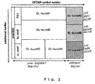
- FIG. 2 is a schematic diagram showing a configuration of a frame used in a radio communication system according to a first exemplary embodiment
- FIG. 3 includes schematic diagrams showing configurations of frames used for different sectors.
- FIGS. 2 and 3 show configurations of downlink sub-frames used for transmission of user data in the forward direction in the radio communication system that divides each cell into three sectors. However, the cell is not always divided into three sectors and can be divided into six sectors, for example.
- the frame used in the radio communication system includes a downlink burst section used for transmission of user data, and the downlink burst section is divided along the time axis into a segment region and a non-segment region.
- the segment region is a region of the downlink burst section used for transmission of user data to an MS that exists in a sector edge or a cell edge (referred to as interference region hereinafter).
- the non-segment region is a region of the downlink burst section used for transmission of user data to an MS that does not exist in the interference region.
- the non-segment region is used also for transmission of control information (a preamble, an FCH, a UL map and a DL map) to each MS.
- FIG. 2 shows an example in which DL-bursts #1 to #4 of the downlink burst section are assigned to the non-segment region, and DL-bursts #5 to #7 of the downlink burst section are assigned to the segment region.
- the sub-carriers used for the cell are divided into the number of sectors, and each sector uses a different sub-carrier.
- FIGS. 2 and 3 show an example in which DL-burst #5 of the downlink burst section is used exclusively for a first sector, DL-burst #6 of the downlink burst section is used exclusively for a second sector, and DL-burst #7 of the downlink burst section is used exclusively for a third sector. Since each sector uses a different sub-carrier in this way, an inter-sector interference or an inter-cell interference at an MS that exists in the interference region can be prevented.
- the MS can detect the control information shown in FIGS. 2 and 3 to some degree. Therefore, in the radio communication system according to the present invention, the control information is transmitted simultaneously to the sectors.
- the segment region is allocated among the sectors in such a manner that neither adjacent sectors in a cell nor adjacent sectors of adjacent cells share the same subchannel.
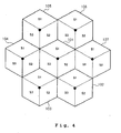
- FIG. 4 shows an arrangement of sectors that minimizes inter-sector interference or inter-cell interference.
- FIG. 4 shows an arrangement of sectors of a 3-sectors-per-cell radio communication system, in which cells 102 to 107 adjacent to each other are arranged around cell 101, and cells 101 to 107 are each divided into three sectors S1, S2 and S3.
- all the channels used for a cell are divided into three resource blocks (subchannels), one subchannel is assigned to each sector S1, S2, S3 in a one-to-one correspondence, and the sectors are arranged in such a manner that any sector of a cell does not share the same subchannel with a sector of an adjacent cell.
- sectors S1, S2 and S3 of cell 101 are not adjacent to any sector of other cells 102 to 107 that is assigned the same sector number.
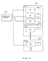
- FIG. 5 is a block diagram showing a configuration of the radio communication system.
- the radio communication system includes BSs 402 1 to 402 3 provided for three sectors forming each of cells 401 1 to 401 X (X represents a positive integer); and scheduling device 403 that is connected to BSs 402 1 to 402 3 provided in each of cells 401 1 to 401 X and that controls assignment of a subchannel used for transmission and reception of user data.
- cells 401 1 to 401 X will be generically referred to as cell 401
- BSs 402 1 to 402 3 will be generically referred to as BS 402.
- the MS (not shown) measures the reception quality of frames received from the BS that administers the service area (sector) in which the MS exists (referred to as administering BS hereinafter) and from the BS that administers an adjacent service area (sector) and informs the administering BS of the measurement result. More specifically, the MS measures the CINR (Carrier to Interference and Noise Ratio) value of the signal received from BS 402 as the reception quality. Measuring methods for the CINR value are described in Japanese Patent Laid-Open Nos. 2005-204307 and 2006-014295 and the section "8.4.11.3 CINR mean and standard deviation" of Non-patent Documents 1 and 2, for example.
- CINR Carrier to Interference and Noise Ratio
- BS 402 acquires the measurement result of the reception quality from each MS in the sector administered by the BS itself (referred to as allocated sector hereinafter) and determines whether or not there is an MS existing in the interference region in the allocated sector. Then, BS 402 calculates the number of MSs existing in the interference region and reports the calculation result to scheduling device 403 as positional statistics information.
- scheduling device 403 determines the number of subchannels in the segment region to be assigned to each BS 402 and informs each BS 402 of the number of subchannels.
- BS 402 configures the segment region and the non-segment region of the downlink burst section according to the information from scheduling device 403 and assigns the subchannels in the segment region used for the allocated sector to the MSs that exist in the interference region and the subchannels in the non-segment region to the MSs that do not exist in the interference region.
- the segment region always includes an unused frequency region (sub-carrier). Therefore, BS 402 allocates the transmission power for the sub-carrier that is not used in the BS to the sub-carrier that is used in the BS. Therefore, according to the present invention, even for the segment region, a modulation method preformed at a high transmission rate can be used for transmission of user data.
- the number of subchannels in the segment region can be equal to the number of the interfering MSs. If there is no MS existing in the interference region, or if any MS existing in the interference region does not intend to communicate with BS 402, the subchannels in the segment region can be allocated to an MS that does not exist in the interference region.
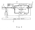
- FIG. 6 is a block diagram showing configuration of BS 402 shown in FIG. 5 .
- BS 402 includes antenna device 11, radio communication part 12, power supply device 13, memory 14 and CPU 15.
- CPU 15 controls the entire operation of the BS according to a program stored in memory 14, for example.
- Memory 14 stores data to be transmitted from the BS to an MS or data received from an MS.
- Power supply device 13 supplies a desired power supply voltage to each device (radio communication part 12, memory 14 and CPU 15) in the BS.
- Radio communication part 12 includes transmitting part 121 that modulates transmission data into a radio frequency (RF) signal by frequency conversion and transmits the RF signal by amplifying the RF signal to a power required for transmission, receiving part 122 that amplifies the received RF signal and demodulates the signal into a base band signal by frequency conversion, switching part 123 that outputs the RF signal from transmitting part 121 to antenna device 11 when transmitting data and outputs the RF signal received at antenna device 11 to receiving part 122 when receiving data, oscillator 124 that produces a local signal required for the frequency conversion conducted by transmitting part 121 and receiving part 122, and communication control part 125 that performs desired processing (coding, decoding, error correction, or the like) on transmitted or received data and that controls the communication operation of radio communication part 12 according to the OFDMA system.
- RF radio frequency
- Transmitting part 121 includes a mixer used in a well-known modulating circuit or used for frequency conversion, a power amplifier that amplifies the RF signal and the like.
- Receiving part 122 includes a mixer used in a well-known modulating circuit or used for frequency conversion, a low-noise amplifier that amplifies the received RF signal and the like.
- Communication control part 125 includes an A/D (analog to digital) converter or a D/A (digital to analog) converter, a memory, an LSI or DSP including various kinds of logic circuits, and the like. Communication control part 125 excluding the A/D converter or D/A converter can be implemented by processing performed by CPU 15 according to a program.
- the MS essentially includes the same components as the BS shown in FIG. 6 and further includes a user interface, such as a speaker, a display and a manipulation button.
- Scheduling device 403 is implemented by a computer, such as a server device.
- FIG. 7 is a flowchart for illustrating a procedure conducted by the scheduling device shown in FIG. 5 .
- scheduling device 403 first instructs BS 402 for each sector to report the positional statistics information of the allocated sector at every predetermined cycle (step 601). Then, in order to determine whether each MS in the allocated sector exists in the interference region or not, BS 402 instructs each MS to inform the BS of the CINR value of the BS and the CINR value of the BS for an adjacent sector (referred to as adjacent BS hereinafter). Specifically, BS 402 transmits a frame referred to as MOB_SCN-RSP (see the Non-patent Document 1) prescribed according to the OFDMA to each MS in the allocated sector.
- MOB_SCN-RSP see the Non-patent Document 1
- Each MS measures the CINR value of the BS that transmits the frame thereto (referred to as administering BS hereinafter) and the CINR value of the adjacent BS and reports the measurement result to the administering BS using the frame referred to as MOB_SCN-REP (see the Non-patent Document 1) prescribed according to the OFDMA.
- BS 402 determines whether the MSs exist in the interference region or not. Specifically, when the difference between the CINR values of the BS and the adjacent BS is small, or when the CINR value of the BS is smaller than the CINR value of the adjacent BS, BS 402 determines that the MS that has reported those CINR values exists in the interference region.
- BS 402 calculates the number of MSs determined to exist in the interference region (the number of the interfering MSs) and reports the calculation result to scheduling device 403 as positional statistics information.
- scheduling device 403 When scheduling device 403 receives positional statistics information from each BS 402 (step 602), scheduling device 403 determines whether or not there is an MS existing in the interference region based on the positional statistics information for each sector (step.603). For a sector for which it is determined that there is no MS existing in the interference region, scheduling device 403 sets the number of subchannels used in the segment region at "0" (step 604). For a sector for which it is determined that there is an MS existing in the interference region, scheduling device 403 calculates the number of subchannels in the segment region corresponding to the number of the interfering MSs (step 605). The number of subchannels in the segment region is equal to the number of the interfering MSs, for example.
- scheduling device 403 calculates the number of subchannels used in the segment region for each sector, scheduling device 403 informs each BS of the calculation result (step 606).
- BS 402 Based on the number of subchannels that BS 402 reported from scheduling device 403, BS 402 sets the segment region including the number of subchannels in the frame and designates the remaining region as the non-segment region. Then, BS 402 allocates the subchannels in the segment region among the MSs existing in the interference region and allocates the subchannels in the non-segment region among the remaining MSs. If any MS existing in the interference region does not communicate with BS 402 nor request a band, the subchannels in the segment region can be allocated to the MSs that do not exist in the interference region.
- BS 402 allocates the transmission power for the sub-carrier that is not used in the BS to the sub-carrier that is used in the BS.
- the CINR value at the MS in the interference region increases by about 4.8 dB. Therefore, BS 402 can transmit user data to the MS existing in the segment region using a modulation method conducted at a high transmission rate.
- the downlink sub-frame is divided into the segment region and the non-segment region along the time axis, and part of the segment region that uses a subchannel that is different from the subchannel used for the adjacent sector is assigned to an MS existing in the interference region. Therefore, in the radio communication system, the BS can separate the subchannel of the allocated sector from the subchannel of the adjacent sector, which is an interference source, along the time axis and the frequency axis.
- the segment region is allocated among sectors in such a manner that neither adjacent sectors in a cell nor adjacent sectors of adjacent cells share the same subchannel, the inter-sector interference or inter-cell interference at the MS that exists in the interference region is minimized, and therefore, the transmission capacity of each sector increases.
- the MS that does not exist in the interference region can use the non-segment region to transmit user data at a transmission rate requested by the MS.
- the segment region can be allocated to an MS that does not exist in the interference region.
- the segment region always includes a sub-carrier that is not used in the BS, even if the power for the sub-carrier is allocated to transmission of the sub-carrier that is used in the BS, there is no possibility that interference will occur because the adjacent sectors are separated along the frequency axis. Therefore, user data can be transmitted using a modulation method conducted at a high transmission rate by concentrating the transmission power on the used sub-carrier in the segment region.
- scheduling device 403 has only to inform each BS 402 of the number of sub-carriers provided in the segment region and does not have to conduct complicated information exchange with BS 402. Therefore, channels can be efficiently used according to the situation.
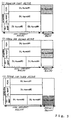
- FIG. 8 is a schematic diagram showing a configuration of a frame used in the radio communication system according to the second exemplary embodiment. As in the first exemplary embodiment, FIG. 8 shows a configuration of a downlink sub-frame used for transmission of user data in the forward direction in a 3-sectors-per-cell radio communication system.
- the radio communication system according to the second exemplary embodiment designates each frame as a segment region or a non-segment region, rather than dividing one frame into the segment region and the non-segment region as in the first exemplary embodiment. That is, the radio communication system according to the second exemplary embodiment produces a non-segment symbol, which is a frame including only a non-segment region, and a segment symbol, which is a frame including only a segment region.
- User data for an MS that exists in the interference region is assigned to the segment symbol
- user data for an MS that does not exist in the interference region is assigned to the non-segment symbol.
- a scheduling device carries out the same process as the process from steps 601 to 603 shown in FIG. 7 .
- the number of segment symbols is set at "0"
- the number of segment symbols corresponding to the number of the interfering MSs is calculated.
- the number of segment symbols is equal to the number of the interfering MSs, for example.
- the scheduling device informs each BS of the number of segment symbols for the BS and the frame number (start frame number) N at which transmission of user data using the segment symbols and the non-segment symbols is started.
- the BS Based on the number of segment symbols and the start frame number N reported by the scheduling device, the BS produces a segment symbol and a non-segment symbol. Then, as shown in FIG. 8 , the BS transmits the non-segment symbol as an N-th frame, receives user data transmitted from each MS using an uplink frame (UL sub-frame), and then, transmits the segment symbol as a (N+1)-th frame. Next, the BS repeats the same transmission/reception process until the indicated number of segment symbols are transmitted.
- the remaining configuration and operation are the same as those in the first exemplary embodiment, and therefore, descriptions thereof will be omitted.
- the BS allocates the transmission power for the sub-carrier that is not used in the BS to the sub-carrier that is used in the BS in the segment symbol.
- the CINR value at the MS in the interference region increases by about 4.8 dB. Therefore, BS 402 can transmit user data to the MS that exists in the segment region using a modulation method conducted at a high transmission rate.
- the present invention can be applied to a configuration in which the scheduling device cannot quickly assign channels to each BS, because the segment region and the non-segment region are assigned on a frame basis.
- An example 1 describes a radio communication system based on an OFDMA system, comprising a base station that is provided for each sector and that communicates with a terminal station by radio, wherein said base station transmits user data to said terminal station using a frame that is divided along a time axis into:
- An example 2 describes the radio communication system according to example 1, further comprising a scheduling device that calculates the number of interfering terminal stations, which is the number of terminal stations that exist in said sector edge or said cell edge, using positional statistics information reported by said base station that indicates the number of terminal stations that are determined to exist in said sector edge or said cell edge, that determines the number of subchannels in said segment region that are assigned to each base station based on the calculated number of interfering terminal stations, and that informs each base station of the number of subchannels.
- a scheduling device that calculates the number of interfering terminal stations, which is the number of terminal stations that exist in said sector edge or said cell edge, using positional statistics information reported by said base station that indicates the number of terminal stations that are determined to exist in said sector edge or said cell edge, that determines the number of subchannels in said segment region that are assigned to each base station based on the calculated number of interfering terminal stations, and that informs each base station of the number of subchannels.
- An example 3 describes a radio communication system based on an OFDMA system, comprising a base station that is provided for each sector and that communicates with a terminal station by radio, wherein said base station transmits user data to said terminal station using:
- An example 4 describes the radio communication system according to example 3, further comprising a scheduling device that determines the number of segment symbols assigned to each base station based on positional statistics information reported by said base station that indicates the number of terminal stations that are determined to exist in said sector edge or said cell edge, and that informs each base station of the determined number of segment symbols and a frame number at which transmission of said user data that uses said segment symbol and said non-segment symbol is started.
- An example 5 describes the radio communication system according to any one of examples 1 to 4, wherein said terminal station measures the reception quality of a frame transmitted from the base station that administers the sector in which the terminal station exists and a frame transmitted from the base station that administers a sector adjacent to the sector in which the terminal station exists, and transmits the measurement result to the base station that administers the sector in which the terminal station exists, and said base station determines whether or not the terminal station exists in said sector edge or said cell edge based on the measurement result of the reception quality received from the terminal station.
- An example 6 describes the radio communication system according to any one of examples 1 to 5, wherein said base station allocates a transmission power for a frequency region in the segment region that is not used in the base station to a frequency region that is used in the base station and transmits the user data by selecting a modulation method conducted at a higher transmission rate from among modulation methods available in the OFDMA system.
- An example 7 describes a base station that is provided for each sector and that communicates with a terminal station by radio according to an OFDMA system, comprising a radio communication part that transmits user data to said terminal station using a frame that is divided along a time axis into:
- An example 8 describes a base station that is provided for each sector and that communicates with a terminal station by radio based according to an OFDMA system, comprising a radio communication part that transmits user data to said terminal station using:
- An example 9 describes the base station according to example 7 or 8, wherein said radio communication part determines whether or not the terminal station exists in said sector edge or said cell edge based on the measurement result of the reception quality received from the terminal station.
- An example 10 describes the base station according to any one of examples 7 to 9, wherein said radio communication part allocates a transmission power for a frequency region in the segment region that is not used in the base station to a frequency region that is used in the base station and transmits the user data by selecting a modulation method conducted at a higher transmission rate from among modulation methods available in the OFDMA system.
- An example 11 describes a radio communication method for transmitting user data to a terminal station according to an OFDMA system from a base station that is provided for each sector, said method comprising:
- An example 12 describes the radio communication method according to example 11, further comprising:
- An example 13 describes a radio communication method for transmitting user data to a terminal station according to an OFDMA system from a base station that is provided for each sector, said method comprising:
- An example 14 describes the radio communication method according to example 13, further comprising:
- An example 15 describes the radio communication method according to any one of examples 11 to 14, said terminal station measures the reception quality of a frame transmitted from the base station that administers the sector in which the terminal station exists and a frame transmitted from the base station that administers a sector adjacent to the sector in which the terminal station exists, and transmits the measurement result to the base station that administers the sector in which the terminal station exists, and said base station determines whether or not the terminal station exists in said sector edge or said cell edge based on the measurement result of the reception quality received from the terminal station.
- An example 16 describes the radio communication method according to any one of examples 11 to 15, wherein said base station allocates a transmission power for a frequency region in the segment region that is not used in the base station to a frequency region that is used in the base station and transmits the user data by selecting a modulation method conducted at a higher transmission rate from among modulation methods available in the OFDMA system.
Applications Claiming Priority (1)
| Application Number | Priority Date | Filing Date | Title |
|---|---|---|---|
| JP2007206523A JP4412505B2 (ja) | 2007-08-08 | 2007-08-08 | 無線通信システム |
Publications (3)
| Publication Number | Publication Date |
|---|---|
| EP2023559A2 true EP2023559A2 (de) | 2009-02-11 |
| EP2023559A3 EP2023559A3 (de) | 2009-09-30 |
| EP2023559B1 EP2023559B1 (de) | 2011-02-23 |
Family
ID=40202093
Family Applications (1)
| Application Number | Title | Priority Date | Filing Date |
|---|---|---|---|
| EP08014072A Expired - Fee Related EP2023559B1 (de) | 2007-08-08 | 2008-08-06 | Funkkommunikationssystem |
Country Status (6)
| Country | Link |
|---|---|
| US (1) | US20090042579A1 (de) |
| EP (1) | EP2023559B1 (de) |
| JP (1) | JP4412505B2 (de) |
| CN (1) | CN101437235A (de) |
| DE (1) | DE602008005068D1 (de) |
| TW (1) | TW200922187A (de) |
Cited By (4)
| Publication number | Priority date | Publication date | Assignee | Title |
|---|---|---|---|---|
| CN101958874A (zh) * | 2010-10-25 | 2011-01-26 | 四川大学 | 基于角分复用的双正交频分多址蜂窝系统 |
| EP2579656A4 (de) * | 2010-05-26 | 2015-10-07 | Sony Corp | Drahtlose kommunikationsvorrichtung und drahtloskommunikationsverfahren |
| EP3313009A4 (de) * | 2015-06-19 | 2018-06-20 | Panasonic Intellectual Property Corporation of America | Sendeverfahren, empfangsverfahren, sendevorrichtung und empfangsvorrichtung |
| EP3313008A4 (de) * | 2015-06-17 | 2018-06-20 | Panasonic Intellectual Property Corporation of America | Sendeverfahren, empfangsverfahren, sendevorrichtung und empfangsvorrichtung |
Families Citing this family (16)
| Publication number | Priority date | Publication date | Assignee | Title |
|---|---|---|---|---|
| US8903440B2 (en) * | 2004-01-29 | 2014-12-02 | Qualcomm Incorporated | Distributed hierarchical scheduling in an ad hoc network |
| WO2009065263A1 (fr) * | 2007-11-23 | 2009-05-28 | Zte Corporation | Procédé de division de zone de permutation de sous-porteuses et système de configuration d'informations |
| WO2010100857A1 (ja) * | 2009-03-02 | 2010-09-10 | 日本電気株式会社 | 移動体通信システムの無線基地局及び干渉平準化方法 |
| KR101495247B1 (ko) | 2009-03-20 | 2015-02-24 | 삼성전자주식회사 | 펨토 기지국들을 포함하는 통신 시스템을 위한 전송 프레임및 자원 할당 방법 |
| KR101498067B1 (ko) * | 2009-04-14 | 2015-03-03 | 엘지전자 주식회사 | 무선 통신 시스템에서 데이터 전송 및 수신 방법 |
| US9178593B1 (en) * | 2009-04-21 | 2015-11-03 | Marvell International Ltd. | Directional channel measurement and interference avoidance |
| JP5205330B2 (ja) | 2009-04-27 | 2013-06-05 | 株式会社日立製作所 | 無線通信システムおよび無線通信方法ならびに基地局装置 |
| JP5249863B2 (ja) | 2009-06-12 | 2013-07-31 | 株式会社日立製作所 | 基地局装置及び干渉低減方法 |
| JP5297943B2 (ja) | 2009-08-25 | 2013-09-25 | 株式会社日立製作所 | 無線リソースの割り当て方法および基地局装置 |
| JP5279677B2 (ja) * | 2009-10-13 | 2013-09-04 | 株式会社日立製作所 | 無線通信システム、無線基地局装置及び無線通信方法 |
| JP5314584B2 (ja) | 2009-12-09 | 2013-10-16 | 株式会社日立製作所 | セルラ無線通信システム、無線基地局装置及び無線端末装置 |
| US8774848B2 (en) * | 2011-10-11 | 2014-07-08 | Fujitsu Limited | System and method for enhancing cell-edge performance in a wireless communication network |
| WO2016203723A1 (ja) * | 2015-06-17 | 2016-12-22 | パナソニック インテレクチュアル プロパティ コーポレーション オブ アメリカ | 送信方法、受信方法、送信装置、及び受信装置 |
| CN112020890A (zh) * | 2018-04-27 | 2020-12-01 | 索尼公司 | 无线通信设备和无线通信方法 |
| JP7233181B2 (ja) * | 2018-08-23 | 2023-03-06 | 日本無線株式会社 | 無線通信システム |
| US11659427B2 (en) * | 2020-04-27 | 2023-05-23 | Spirent Communications, Inc. | Efficient real-time 802.11ax OFDMA statistics logging |
Citations (4)
| Publication number | Priority date | Publication date | Assignee | Title |
|---|---|---|---|---|
| JP2005080286A (ja) | 2003-09-02 | 2005-03-24 | Korea Electronics Telecommun | Ofdma・fdd基盤の移動通信システムにおける順方向チャンネルの構成方法及び順方向チャンネルの割当て方法 |
| JP2005204307A (ja) | 2004-01-14 | 2005-07-28 | Samsung Electronics Co Ltd | 通信システムにおける干渉及び雑音推定装置及びその方法 |
| JP2006014295A (ja) | 2004-05-28 | 2006-01-12 | Matsushita Electric Ind Co Ltd | 無線通信装置及び通信品質推定方法 |
| JP2007206523A (ja) | 2006-02-03 | 2007-08-16 | Toshiba Tec Corp | 音声認識装置及び音声認識プログラム |
Family Cites Families (5)
| Publication number | Priority date | Publication date | Assignee | Title |
|---|---|---|---|---|
| US7158563B2 (en) * | 2001-06-01 | 2007-01-02 | The Board Of Trustees Of The Leland Stanford Junior University | Dynamic digital communication system control |
| US7016319B2 (en) * | 2003-03-24 | 2006-03-21 | Motorola, Inc. | Method and apparatus for reducing co-channel interference in a communication system |
| KR100965338B1 (ko) * | 2003-08-18 | 2010-06-22 | 엘지전자 주식회사 | Ofdm 셀룰러 환경에서 셀간 간섭 저감을 위한부반송파 할당방법 |
| US7395074B2 (en) * | 2004-04-08 | 2008-07-01 | Nokia Corporation | Position detection with frequency smoothing |
| US8077694B2 (en) * | 2006-11-28 | 2011-12-13 | Motorola Mobility, Inc. | Intelligent scheduling in a time division duplexing system to mitigate near/far interference scenarios |
-
2007
- 2007-08-08 JP JP2007206523A patent/JP4412505B2/ja not_active Expired - Fee Related
-
2008
- 2008-08-01 TW TW097129272A patent/TW200922187A/zh unknown
- 2008-08-05 CN CNA2008101842321A patent/CN101437235A/zh active Pending
- 2008-08-06 EP EP08014072A patent/EP2023559B1/de not_active Expired - Fee Related
- 2008-08-06 DE DE602008005068T patent/DE602008005068D1/de active Active
- 2008-08-07 US US12/187,497 patent/US20090042579A1/en not_active Abandoned
Patent Citations (4)
| Publication number | Priority date | Publication date | Assignee | Title |
|---|---|---|---|---|
| JP2005080286A (ja) | 2003-09-02 | 2005-03-24 | Korea Electronics Telecommun | Ofdma・fdd基盤の移動通信システムにおける順方向チャンネルの構成方法及び順方向チャンネルの割当て方法 |
| JP2005204307A (ja) | 2004-01-14 | 2005-07-28 | Samsung Electronics Co Ltd | 通信システムにおける干渉及び雑音推定装置及びその方法 |
| JP2006014295A (ja) | 2004-05-28 | 2006-01-12 | Matsushita Electric Ind Co Ltd | 無線通信装置及び通信品質推定方法 |
| JP2007206523A (ja) | 2006-02-03 | 2007-08-16 | Toshiba Tec Corp | 音声認識装置及び音声認識プログラム |
Cited By (8)
| Publication number | Priority date | Publication date | Assignee | Title |
|---|---|---|---|---|
| EP2579656A4 (de) * | 2010-05-26 | 2015-10-07 | Sony Corp | Drahtlose kommunikationsvorrichtung und drahtloskommunikationsverfahren |
| CN105101395A (zh) * | 2010-05-26 | 2015-11-25 | 索尼公司 | 无线通信装置和无线通信方法 |
| US9301255B2 (en) | 2010-05-26 | 2016-03-29 | Sony Corporation | Wireless communication device and wireless communication method |
| US9629086B2 (en) | 2010-05-26 | 2017-04-18 | Sony Corporation | Wireless communication device and wireless communication method |
| CN101958874A (zh) * | 2010-10-25 | 2011-01-26 | 四川大学 | 基于角分复用的双正交频分多址蜂窝系统 |
| CN101958874B (zh) * | 2010-10-25 | 2013-05-22 | 四川大学 | 基于角分复用的双正交频分多址蜂窝系统 |
| EP3313008A4 (de) * | 2015-06-17 | 2018-06-20 | Panasonic Intellectual Property Corporation of America | Sendeverfahren, empfangsverfahren, sendevorrichtung und empfangsvorrichtung |
| EP3313009A4 (de) * | 2015-06-19 | 2018-06-20 | Panasonic Intellectual Property Corporation of America | Sendeverfahren, empfangsverfahren, sendevorrichtung und empfangsvorrichtung |
Also Published As
| Publication number | Publication date |
|---|---|
| TW200922187A (en) | 2009-05-16 |
| EP2023559A3 (de) | 2009-09-30 |
| US20090042579A1 (en) | 2009-02-12 |
| JP2009044397A (ja) | 2009-02-26 |
| JP4412505B2 (ja) | 2010-02-10 |
| DE602008005068D1 (de) | 2011-04-07 |
| EP2023559B1 (de) | 2011-02-23 |
| CN101437235A (zh) | 2009-05-20 |
Similar Documents
| Publication | Publication Date | Title |
|---|---|---|
| EP2023559B1 (de) | Funkkommunikationssystem | |
| US7764649B2 (en) | Handover method and system in a broadband wireless access communication system | |
| US10772079B2 (en) | Method and system for signalling resource allocation information in an asymmetric multicarrier communication network | |
| US7299048B2 (en) | System and method for performing soft handover in broadband wireless access communication system | |
| US7515562B2 (en) | Apparatus and method for supporting soft handover in broadband wireless access communication system | |
| US7983664B2 (en) | Transmission method, wireless base station, and wireless communication method | |
| US20050288026A1 (en) | System and method for supporting soft handover in broadband wireless access communication system | |
| KR100957408B1 (ko) | 광대역 무선 분할 다중 접속 통신 시스템에서 핸드오버 지원을 위한 방법 및 장치 | |
| US8134967B2 (en) | Method and apparatus for use in wireless communications | |
| US20050288027A1 (en) | Apparatus and method for supporting soft handover in broadband wireless access communication system | |
| US20100260163A1 (en) | OFDMA communication apparatus | |
| US20060079235A1 (en) | System and method for handover in a broadband wireless access communication system | |
| US20110228798A1 (en) | System and method for using resources in a communication system | |
| KR20210094076A (ko) | 가드 대역 지시 방법 및 장치 | |
| KR20090037910A (ko) | 무선 통신 시스템에서 구성가능한 다운링크 및 업링크 채널들 | |
| TW201132039A (en) | OFDMA cellular network and method for mitigating interference | |
| EP3507920B1 (de) | Verfahren und drahtloser knot zur ermöglichung der koexistenz von kommunikationssystemen | |
| US8493930B2 (en) | Communication system, base station and mobile station used in the communication system, and base station switching method | |
| US20080159249A1 (en) | Radio communication apparatus and radio communication method | |
| US20110044214A1 (en) | Mobile communication system | |
| US10420074B2 (en) | Base station and user equipment | |
| US9706566B2 (en) | Uplink interference mitigation method and apparatus | |
| KR20080042521A (ko) | 광대역 무선 통신 시스템에서 핸드오버 장치 및 방법 | |
| KR101062053B1 (ko) | 광대역 무선 통신 시스템에서 자원 할당 장치 및 방법 | |
| KR20060056210A (ko) | 직교 주파수 분할 다중 접속 통신 시스템에서 핸드오버서비스 방법 |
Legal Events
| Date | Code | Title | Description |
|---|---|---|---|
| PUAI | Public reference made under article 153(3) epc to a published international application that has entered the european phase |
Free format text: ORIGINAL CODE: 0009012 |
|
| AK | Designated contracting states |
Kind code of ref document: A2 Designated state(s): AT BE BG CH CY CZ DE DK EE ES FI FR GB GR HR HU IE IS IT LI LT LU LV MC MT NL NO PL PT RO SE SI SK TR |
|
| AX | Request for extension of the european patent |
Extension state: AL BA MK RS |
|
| PUAL | Search report despatched |
Free format text: ORIGINAL CODE: 0009013 |
|
| AK | Designated contracting states |
Kind code of ref document: A3 Designated state(s): AT BE BG CH CY CZ DE DK EE ES FI FR GB GR HR HU IE IS IT LI LT LU LV MC MT NL NO PL PT RO SE SI SK TR |
|
| AX | Request for extension of the european patent |
Extension state: AL BA MK RS |
|
| RIC1 | Information provided on ipc code assigned before grant |
Ipc: H04W 72/12 20090101ALI20090827BHEP Ipc: H04L 5/00 20060101AFI20090827BHEP |
|
| 17P | Request for examination filed |
Effective date: 20100329 |
|
| AKX | Designation fees paid |
Designated state(s): DE FR GB IT |
|
| GRAP | Despatch of communication of intention to grant a patent |
Free format text: ORIGINAL CODE: EPIDOSNIGR1 |
|
| GRAS | Grant fee paid |
Free format text: ORIGINAL CODE: EPIDOSNIGR3 |
|
| GRAA | (expected) grant |
Free format text: ORIGINAL CODE: 0009210 |
|
| AK | Designated contracting states |
Kind code of ref document: B1 Designated state(s): DE FR GB IT |
|
| REG | Reference to a national code |
Ref country code: GB Ref legal event code: FG4D |
|
| REF | Corresponds to: |
Ref document number: 602008005068 Country of ref document: DE Date of ref document: 20110407 Kind code of ref document: P |
|
| REG | Reference to a national code |
Ref country code: DE Ref legal event code: R096 Ref document number: 602008005068 Country of ref document: DE Effective date: 20110407 |
|
| PLBE | No opposition filed within time limit |
Free format text: ORIGINAL CODE: 0009261 |
|
| STAA | Information on the status of an ep patent application or granted ep patent |
Free format text: STATUS: NO OPPOSITION FILED WITHIN TIME LIMIT |
|
| 26N | No opposition filed |
Effective date: 20111124 |
|
| REG | Reference to a national code |
Ref country code: DE Ref legal event code: R097 Ref document number: 602008005068 Country of ref document: DE Effective date: 20111124 |
|
| REG | Reference to a national code |
Ref country code: FR Ref legal event code: ST Effective date: 20120430 |
|
| PG25 | Lapsed in a contracting state [announced via postgrant information from national office to epo] |
Ref country code: IT Free format text: LAPSE BECAUSE OF FAILURE TO SUBMIT A TRANSLATION OF THE DESCRIPTION OR TO PAY THE FEE WITHIN THE PRESCRIBED TIME-LIMIT Effective date: 20110223 |
|
| REG | Reference to a national code |
Ref country code: DE Ref legal event code: R119 Ref document number: 602008005068 Country of ref document: DE Effective date: 20120301 |
|
| PG25 | Lapsed in a contracting state [announced via postgrant information from national office to epo] |
Ref country code: FR Free format text: LAPSE BECAUSE OF NON-PAYMENT OF DUE FEES Effective date: 20110831 |
|
| PGFP | Annual fee paid to national office [announced via postgrant information from national office to epo] |
Ref country code: GB Payment date: 20120801 Year of fee payment: 5 |
|
| PG25 | Lapsed in a contracting state [announced via postgrant information from national office to epo] |
Ref country code: DE Free format text: LAPSE BECAUSE OF NON-PAYMENT OF DUE FEES Effective date: 20120301 |
|
| GBPC | Gb: european patent ceased through non-payment of renewal fee |
Effective date: 20130806 |
|
| PG25 | Lapsed in a contracting state [announced via postgrant information from national office to epo] |
Ref country code: GB Free format text: LAPSE BECAUSE OF NON-PAYMENT OF DUE FEES Effective date: 20130806 |