EP2023082A1 - Gyroscope micro-électromécanique avec dispositif de lecture en circuit ouvert et son procédé de commande - Google Patents
Gyroscope micro-électromécanique avec dispositif de lecture en circuit ouvert et son procédé de commande Download PDFInfo
- Publication number
- EP2023082A1 EP2023082A1 EP07425417A EP07425417A EP2023082A1 EP 2023082 A1 EP2023082 A1 EP 2023082A1 EP 07425417 A EP07425417 A EP 07425417A EP 07425417 A EP07425417 A EP 07425417A EP 2023082 A1 EP2023082 A1 EP 2023082A1
- Authority
- EP
- European Patent Office
- Prior art keywords
- mass
- charge
- reading
- gyroscope
- resonance frequency
- Prior art date
- Legal status (The legal status is an assumption and is not a legal conclusion. Google has not performed a legal analysis and makes no representation as to the accuracy of the status listed.)
- Granted
Links
- 238000000034 method Methods 0.000 title claims description 18
- 230000010355 oscillation Effects 0.000 claims abstract description 18
- 238000006073 displacement reaction Methods 0.000 claims abstract description 17
- 230000004044 response Effects 0.000 claims abstract description 9
- 238000001514 detection method Methods 0.000 claims description 63
- 230000002596 correlated effect Effects 0.000 claims description 10
- 230000001755 vocal effect Effects 0.000 claims description 10
- 230000001276 controlling effect Effects 0.000 claims description 5
- 238000005070 sampling Methods 0.000 claims description 5
- 238000001914 filtration Methods 0.000 claims description 3
- 230000008878 coupling Effects 0.000 claims description 2
- 238000010168 coupling process Methods 0.000 claims description 2
- 238000005859 coupling reaction Methods 0.000 claims description 2
- 230000010363 phase shift Effects 0.000 claims 2
- 238000012986 modification Methods 0.000 abstract description 2
- 230000004048 modification Effects 0.000 abstract description 2
- 238000012545 processing Methods 0.000 description 8
- 230000008569 process Effects 0.000 description 6
- 238000010586 diagram Methods 0.000 description 5
- 230000000284 resting effect Effects 0.000 description 5
- 239000003990 capacitor Substances 0.000 description 4
- 230000000875 corresponding effect Effects 0.000 description 4
- 230000001133 acceleration Effects 0.000 description 3
- 238000011144 upstream manufacturing Methods 0.000 description 3
- 230000007547 defect Effects 0.000 description 2
- 238000013461 design Methods 0.000 description 2
- 230000000694 effects Effects 0.000 description 2
- 238000005516 engineering process Methods 0.000 description 2
- 230000005284 excitation Effects 0.000 description 2
- 238000004519 manufacturing process Methods 0.000 description 2
- 230000010349 pulsation Effects 0.000 description 2
- 230000003213 activating effect Effects 0.000 description 1
- 230000003321 amplification Effects 0.000 description 1
- 238000006243 chemical reaction Methods 0.000 description 1
- 238000004891 communication Methods 0.000 description 1
- 238000011161 development Methods 0.000 description 1
- 239000006185 dispersion Substances 0.000 description 1
- 230000009977 dual effect Effects 0.000 description 1
- 230000006355 external stress Effects 0.000 description 1
- 239000000284 extract Substances 0.000 description 1
- 230000006870 function Effects 0.000 description 1
- 230000003993 interaction Effects 0.000 description 1
- 239000000463 material Substances 0.000 description 1
- 238000003199 nucleic acid amplification method Methods 0.000 description 1
- 230000003534 oscillatory effect Effects 0.000 description 1
- 230000009467 reduction Effects 0.000 description 1
- 239000004065 semiconductor Substances 0.000 description 1
- 230000006641 stabilisation Effects 0.000 description 1
- 238000011105 stabilization Methods 0.000 description 1
- 238000012546 transfer Methods 0.000 description 1
Images

Classifications
-
- G—PHYSICS
- G01—MEASURING; TESTING
- G01C—MEASURING DISTANCES, LEVELS OR BEARINGS; SURVEYING; NAVIGATION; GYROSCOPIC INSTRUMENTS; PHOTOGRAMMETRY OR VIDEOGRAMMETRY
- G01C19/00—Gyroscopes; Turn-sensitive devices using vibrating masses; Turn-sensitive devices without moving masses; Measuring angular rate using gyroscopic effects
- G01C19/56—Turn-sensitive devices using vibrating masses, e.g. vibratory angular rate sensors based on Coriolis forces
- G01C19/5719—Turn-sensitive devices using vibrating masses, e.g. vibratory angular rate sensors based on Coriolis forces using planar vibrating masses driven in a translation vibration along an axis
- G01C19/5733—Structural details or topology
- G01C19/5755—Structural details or topology the devices having a single sensing mass
- G01C19/5762—Structural details or topology the devices having a single sensing mass the sensing mass being connected to a driving mass, e.g. driving frames
-
- G—PHYSICS
- G01—MEASURING; TESTING
- G01C—MEASURING DISTANCES, LEVELS OR BEARINGS; SURVEYING; NAVIGATION; GYROSCOPIC INSTRUMENTS; PHOTOGRAMMETRY OR VIDEOGRAMMETRY
- G01C19/00—Gyroscopes; Turn-sensitive devices using vibrating masses; Turn-sensitive devices without moving masses; Measuring angular rate using gyroscopic effects
- G01C19/56—Turn-sensitive devices using vibrating masses, e.g. vibratory angular rate sensors based on Coriolis forces
- G01C19/5719—Turn-sensitive devices using vibrating masses, e.g. vibratory angular rate sensors based on Coriolis forces using planar vibrating masses driven in a translation vibration along an axis
- G01C19/5726—Signal processing
Definitions
- the present invention relates to a micro-electro-mechanical gyroscope with open-loop reading device and a corresponding method for controlling a micro-electro-mechanical gyroscope.
- MEMS micro-electro-mechanical systems
- MEMS systems of this type are usually based upon micro-electro-mechanical structures comprising at least one mass, which is connected to a fixed body (stator) through springs and is movable with respect to the stator according to pre-determined degrees of freedom.
- the movable mass and the stator are capacitively coupled by a plurality of respective comb-fingered and mutually facing electrodes so as to form capacitors.
- the movement of the movable mass with respect to the stator modifies the capacitance of the capacitors. From here it is possible to trace back to the relative displacement of the movable mass with respect to the fixed body and hence to the force applied.
- MEMS gyroscopes in particular, have a more complex electro-mechanical structure, which comprises two masses, movable with respect to the stator and coupled to one another so as to have one relative degree of freedom.
- the two movable masses are both capacitively coupled to the stator.
- One of the masses is dedicated to driving and is maintained in oscillation at the resonance frequency.
- the other mass is driven in the oscillatory motion and, in the case of rotation of the microstructure with respect to a pre-determined gyroscopic axis with an angular velocity, is subject to a Coriolis' force proportional to the angular velocity itself.
- the driven mass operates as an accelerometer, which enables detection of the Coriolis' force and acceleration and hence tracing-back to the angular velocity.
- a MEMS gyroscope requires, in addition to the microstructure, a driving device, which has the task of maintaining the movable mass in oscillation at the resonance frequency, and a device for reading the displacements of the driven mass, according to the degree of freedom of the driving mass.
- Such displacements in fact, indicate the Coriolis' force and, consequently, the angular velocity and can be detected through electric reading signals correlated to the variations of the capacitive coupling between the driven mass and the stator.
- the reading signals caused by the rotation of the gyroscope and correlated to the angular velocity, are in the form of dual-side-band, suppressed-carrier signals (DSB-SC; the carrier is in this case the velocity of oscillation of the driving mass and has a frequency equal to the mechanical resonance frequency).
- DSB-SC dual-side-band, suppressed-carrier signals
- the MEMS gyroscope Since, however, the MEMS gyroscope has a complex structure and the electro-mechanical interactions between the movable masses and stator are frequently non-linear, the useful signal components are frequently superimposed on spurious components, which are not significant for measuring the angular velocity.
- the spurious components can be due to several causes. For example, reading the capacitance between the movable masses and the stator inherently perturbs the forces caused by driving and by rotation of the microstructure (producing the so-called phenomenon of "electrostatic softening", which in practice modifies the resonance frequency of the micro-electro-mechanical structure).
- the charge displacements induced and detected modify the electrostatic forces between the capacitively coupled elements and affect the dynamics of the system.
- a very common defect depends on the fact that the mass used for driving oscillates in a direction not perfectly coinciding with the degree of freedom envisaged in the design stage. In this case, the defect of driving affects the useful signal, introducing a component of unknown amplitude at the same frequency as that of the carrier and 90° out of phase.
- the amplitude of the disturbance components is in many cases significant and cannot be simply neglected without introducing unacceptable distortions.
- the aim of the invention is therefore to provide a micro-electro-mechanical gyroscope and a corresponding method for controlling a micro-electro-mechanical gyroscope that will enable a reduction in the influence of the disturbance components superimposed on signal components caused by rotation of the gyroscope itself.
- a micro-electro-mechanical gyroscope and a corresponding method for controlling a micro-electro-mechanical gyroscope are provided, as defined in Claim 1 and Claim 12, respectively.
- a micro-electro-mechanical gyroscope 100 illustrated in a simplified way in the block diagram of Figure 3 , comprises a microstructure 102, obtained using MEMS technology, a driving device 103, and a reading device 104, housed on a support 101.
- the microstructure 102 for example, of the type described in EP-A-1 253 399 , filed in the name of the present applicant, is provided with an actuation system 5 and an inertial sensor 6, including respective movable masses made of semiconductor material. More precisely, the actuation system 5 comprises a driving mass 107, which oscillates, with respect to a fixed structure or stator 109, about a resting position according to a degree of freedom, in particular along a first axis X.
- the actuation system 5 is moreover provided with reading outputs 5a (defined by two stator terminals), for detecting displacements of the driving mass 107 along the first axis X, and with actuation inputs 5b (defined by two further stator terminals), for supplying actuation signals and maintaining the driving mass 107 in oscillation at the resonance frequency ⁇ R , in a known way.
- the reading outputs 5a and the actuation inputs 5b are capacitively coupled to the driving mass 107 in a known way, by comb-fingered electrodes (here not shown).
- the inertial sensor 6 has a detection axis directed along a second axis Y perpendicular to the first axis X and comprises a detection mass 108, mechanically connected to the driving mass 107 by springs (here not shown) so as to be driven in motion with respect to the stator 109 along the first axis X when the driving mass 107 is excited.
- the detection mass 108 is movable with respect to the driving mass 107 and with respect to the stator 109 in the direction of the second axis Y and hence has a further degree of freedom.
- Two first (stator) terminals 6a and a second terminal 6b (directly connected to the detection mass 108) of the inertial sensor 6 enable, respectively, supply of reading signals V S1 , V S2 to the detection mass 108 and detection of the displacements thereof.
- the first terminals 6a are capacitively coupled to the detection mass 108 in a known way, by comb-fingered electrodes (here not shown), while the second terminal 6b is directly connected to said mass.
- the driving device 103 is connected to the microstructure 102 so as to form a feedback control loop 105, including the driving mass 107.
- the driving device 103 exploits the feedback control loop 105 to maintain the driving mass 107 in self-oscillation along the first axis X at its mechanical resonance frequency ⁇ R (for example, 25 krad/s).
- the reading device 104 is of the open-loop type and, in the embodiment described here, is configured to carry out a so-called "single-ended" reading of the displacements of the detection mass 108 along the second axis Y.
- the reading device 104 has: first inputs 104a, connected to the driving device 103 for capturing detection signals V RD1 , V RD2 (in this case voltages); a second input, connected to the second terminal 6b of the inertial sensor 6; first outputs, connected to respective first terminals 6a of the inertial sensor 6 and supplying reading signals V S1 , V S2 ; and a second output 104b, which supplies an output signal S OUT , correlated to the angular velocity ⁇ of the microstructure 102.
- the gyroscope 100 operates in the way described hereinafter.
- the driving mass 107 is set in oscillation along the first axis X by the driving device 103.
- the driving device 103 is coupled to the reading outputs 5a of the actuation system 5 for receiving detection currents I RD1 , I RD2 , which are correlated to the linear velocity of oscillation of the driving mass 107 along the first axis X.
- the driving device 103 On the basis of the detection currents I RD1 , I RD2 the driving device 103 generates feedback driving voltages V FBD1 , V FBD2 having amplitude and phase such as to ensure the conditions of oscillation of the feedback control loop 105 (unit loop gain and substantially zero phase).
- the detection mass 108 is driven in motion along the first axis X by the driving mass 107. Consequently, when the microstructure 102 rotates about a gyroscopic axis perpendicular to the plane of the axes X, Y with a certain instantaneous angular velocity, the detection mass 108 is subjected to a Coriolis' force, which is parallel to the second axis Y and is proportional to the instantaneous angular velocity of the microstructure 102 and to the linear velocity of the two masses 107, 108 along the first axis X.
- M S is the value of the detection mass 108
- ⁇ is the angular velocity of the microstructure 102
- X' is the linear velocity of the two masses 107, 108 along the first axis X.
- the detection signals caused by rotation of the gyroscope and correlated to the angular velocity, are in the form of signals with dual side band and suppressed carrier (DSB-SC; the carrier is in this case the linear velocity X' of oscillation of the driving mass and has a frequency equal to the mechanical resonance frequency ⁇ R ).
- the driving mass 107 is subjected to a Coriolis' force; however, said force is countered by the constraints that impose on the driving mass 107 movement exclusively along the first axis X.
- the Coriolis' force and acceleration to which the detection mass 108 is subjected are read through the inertial sensor 6.
- the inertial sensor 6 supplies detection charge packets Q RS , which are proportional to the capacitive unbalancing caused by the displacement of the detection mass 108 along the second axis Y.
- the detection charge packets Q RS are hence correlated to the Coriolis' force (and acceleration) and to the instantaneous angular velocity of the microstructure 102. More precisely, the charge transferred with the detection charge packets Q RS in successive reading cycles is amplitude-modulated proportionally to the instantaneous angular velocity of the microstructure 102.
- the band of frequencies associated to the modulating quantity i.e., the instantaneous angular velocity, is, however, much lower than the resonance frequency ⁇ R (for example, approximately 30 rad/s).
- detection charge packets Q RS are converted and processed by the reading device 104, which generates the output signal S OUT , as explained hereinafter.
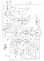
- Figure 4 shows a more detailed diagram of the microstructure 102, of the driving device 103, and of the reading device 104.
- Figure 4 shows: first differential detection capacitances 120 present between the driving mass 107 and respective reading outputs 5a of the actuation system 5; actuation capacitances 121, present between the driving mass 107 and respective actuation inputs 5b of the actuation system 5; and second detection capacitances 122, present between the detection mass 108 and the second terminal 6b of the inertial sensor 6. More precisely, the first differential detection capacitances 120 and the differential actuation capacitances 121 have respective terminals connected to one and the same actuation node 125, which is in turn coupled to the actuation mass 108.
- the driving device 103 comprises a transimpedance amplifier 110 and a feedback stage 111, in itself known.
- the transimpedance amplifier 110 is of a fully differential type and has a pair of inputs connected to the reading outputs 5a of the actuation system 5 for receiving the detection currents I RD1 , I RD2 , which are correlated to the linear velocity of oscillation of the driving mass 107 along the first axis X.
- detection voltages V RD1 , V RD2 are hence present, which also indicate the linear velocity of oscillation of the driving mass 107 along the first axis X.
- the detection voltages V RD1 , V RD2 are sinusoidal, oscillate at the resonance frequency ⁇ R , have equal amplitude and are 180° out of phase with respect to one another.
- the conditions of resonance are ensured by the feedback stage 111, which generates the feedback driving voltages V FBD1 , V FBD2 in such a way that the gain of the feedback control loop 105 is a unit gain and the its phase is zero.
- the outputs of the transimpedance amplifier 110 are moreover connected to the reading device 104, for supply of the detection voltages V RD1 , U RD2 .
- the reading device 104 is of the open-loop type and is configured for carrying out a so-called "single-ended" reading of the displacements of the detection mass 108 along the second axis Y.
- the detection mass 108 is excited by means of the two reading signals V S1 , V S2 , 180° out of phase with respect to one another (see also Figures 5a, 5b ), which are supplied to respective first terminals 6a of the inertial sensor 6.
- the inertial sensor 6 In response to the reading signals V S1 , V S2 , the inertial sensor 6 generates detection charge packets Q RS , which are supplied on the second terminal 6b.
- the detection charge packets Q RS are proportional to the capacitive unbalancing of the second detection capacitances 122, caused by the displacement of the detection mass 108 along the second axis Y.
- the reading device 104 comprises a generator of reading signals 130, a phase generator 131 and, moreover, a processing line 132, which includes a charge amplifier 133, an analog-processing stage 134, a filter 135 and a sampler 136.
- the reading device is provided with a calibration unit 138, of a numeric type, and of a calibration network 140.
- the generator of reading signals 130 is a sampler and has a clock input, connected to the phase generator 131 for receiving a clock signal CK (with a clock period T CK ), and inputs forming the first inputs 104a of the reading circuit 104.
- the inputs are connected to the outputs of the transimpedance amplifier 110 of the driving device 103 and receive respective detection voltages V RD1 , V RD2 .
- the clock signal CK is asynchronous with respect to the oscillation of the driving mass 107 (in practice, the clock frequency 2 ⁇ /T C is not correlated to the resonance frequency ⁇ R ). Also the sampling performed by the generator of reading signals 130 is hence asynchronous with respect to the resonance frequency ⁇ R .
- Outputs of the generator of reading signals 130 are connected to respective first terminals 6a of the inertial sensor 6 and supply respective reading signals V S1 , V S2 .
- the reading signals V S1 , V S2 are generated by sampling and amplification of respective detection signals V RD1 , U RD2 and hence are in the form of square-wave signals of amplitude that is sinusoidally variable with the resonance frequency ⁇ R , 180° out of phase with respect to one another, as shown in Figures 5a, 5b .
- V S ⁇ 2 t - V P sin ⁇ R ⁇ t + ⁇ + V B
- V P is a peak value
- ⁇ is the phase
- V B is a d.c. biasing voltage between the movable mass 108 and the stator 109 (which is zero in Figures 5a, 5b ).
- V P is a peak value
- ⁇ is the phase
- V B is a d.c. biasing voltage between the movable mass 108 and the stator 109 (which is zero in Figures 5a, 5b ).
- the variable t that indicates time is to be understood as being discrete.
- the charge amplifier 133 comprises an operational amplifier 133a and a capacitor 133b connected between a first input of the operational amplifier 133a and its output.
- the first input of the operational amplifier 133a which defines an input of the charge amplifier 133, is connected to the second terminal 6b of the inertial sensor 6 for receiving the detection charge packets Q RS produced by the inertial sensor 6 in response to the reading signals V S1 , V S2 and to rotation of the gyroscope 100.
- a second input of the operational amplifier 133a which defines a second input of the charge amplifier 133, is, instead, connected to the calibration network 140.
- the analog-processing stage 134, the filter 135, and the sampler 136 are cascaded to the charge amplifier 133 so as to process the detection charge packets Q RS (converted into voltage by the charge amplifier 133) and generate the output signal S OUT .
- the filter 135 is of a low-pass type and is configured to eliminate the high-frequency components (2 ⁇ R ) and thus completing the demodulation process.
- the calibration network 140 comprises a resistive divider having variable division ratio and is controlled by the calibration unit 138.
- An output 140a of the calibration network 140 is connected to the second input of the charge amplifier 133 and supplies a calibration voltage V OCAL .
- the second terminal 6b of the inertial sensor 6 is hence used as calibration terminal.
- the calibration voltage V OCAL enables determination of the d.c. biasing voltage V B between the movable mass 108 and the stator 109.
- the calibration unit 138 detects a charge-integration signal S QI in a point of the processing line 132 set downstream of the charge amplifier 133 and upstream of the filter 135.
- the charge-integration signal S QI is detected directly at output from the charge amplifier 133, upstream of the analog-processing stage 134.
- the charge-integration signal S QI may be detected at output from the analog-processing stage 134.
- the component at a frequency 2 ⁇ R which is twice the resonance frequency ⁇ R , is still present in the charge-integration signal S QI .
- the calibration unit 138 extracts the component at frequency 2 ⁇ R from the charge-integration signal S QI and, on the basis of said component, sets the division ratio of the calibration network 140 and, consequently, the value of the calibration voltage V OCAL , as explained hereinafter.
- the reading device 104 operates as follows.
- the detection charge packets Q RS are generated by the inertial sensor 6 in response to excitation of the detection mass 108 by the reading signals V S1 , V S2 and are proportional to the capacitive unbalancing of the second detection capacitances 122. Said capacitive unbalancing is caused also by the amplitude of the reading signals V S1 , V S2 , as well as by the external forces acting on the detection mass 108. Consequently, the charge transferred with the detection charge packets Q RS is correlated, in particular through a proportional component, to the reading signals V S1 , V S2 , which vary at the resonance frequency ⁇ R .
- the use of the reading signals V S1 , V S2 for exciting the detection mass 108 intrinsically enables an operation of demodulation to be carried out. Consequently, signals deriving from the voltage conversion of the detection charge packets Q RS , originally modulated with a carrier frequency given by the linear velocity X' (at the resonance frequency ⁇ R ), are signals already converted down to base band, precisely because the amplitude of the reading signals V S1 , V S2 varies at the resonance frequency ⁇ R .
- the demodulation does not need to be carried out by the processing line 132.
- the charge-integration signal S QI still contains, however, a component at frequency 2 ⁇ R , which is generated by the operation of demodulation and is eliminated only through the low-pass filtering performed by the filter 135.
- the calibration unit 138 acts on the calibration network 140 for minimizing, through the calibration voltage V OCAL , the component at frequency 2 ⁇ R because in this way it is possible to eliminate or reduce significantly at least some disturbance components superimposed on the useful signal.
- the calibration unit 138 detects that the component at frequency 2 ⁇ R has been minimized, the calibration process is interrupted.
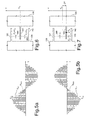
- FIGS 6 and 7 illustrate two stator electrodes 141, 142 and one detection electrode 143 of the detection mass 108.
- the detection electrode 143 is set between the stator electrodes 141, 142 so as to form two capacitors 144, 145, which have respective capacitances C 1 , C 2 .
- the detection mass 108 In a resting position ( Figure 6 ), the detection mass 108 is arranged in such a way that the detection electrode 143 is located at the same distance from the stator electrodes 141, 142, in particular at a distance Y G .
- the capacitances C 1 , C 2 are both equal to a resting capacitance C 0 .
- the capacitances C 1 , C 2 are unbalanced with respect to the resting capacitance C 0 , and a non-zero electrostatic force F E acts on the detection electrode 143 as a result of the reading signals V S1 , V S2 applied to the first terminals 6a.
- the electrostatic force F E moreover depends upon the (d.c.) biasing voltage V B between the movable mass 108 and the stator 109, which is caused by the calibration voltage V OCAL .
- the electrostatic force F E can also be expressed as follows:
- ⁇ t ⁇ V B 2 + B t ⁇ V B + ⁇ t
- the terms ⁇ (t), ⁇ (t) and ⁇ (t) are respectively given by ⁇ t ⁇ 2 ⁇ C 0 ⁇ ⁇ Y Y G 2 ⁇ t ⁇ 2 ⁇ C 0 ⁇ V P ⁇ sin ⁇ R ⁇ t + ⁇ Y G ⁇ t ⁇ 2 ⁇ C 0 ⁇ ⁇ YV P 2 ⁇ sin 2 ⁇ ⁇ R ⁇ t + ⁇ Y G 2
- the electrostatic force F E applied to each detection electrode 143 is hence determined, through the biasing voltage V B , from the calibration voltage V OCAL .
- a large number of important sources of disturbance come in the form of a quadrature component, i.e., 90° out of phase with respect to the carrier (linear velocity X'). This is the case, for example, of a less than perfect alignment between the first (driving) axis X and the second (detection) axis Y.
- the quadrature component of disturbance results in a signal at a frequency 2 ⁇ R , which is added to a d.c. signal.
- the charge variation induced by the electrostatic force F E can hence advantageously be exploited for minimizing the effects of the disturbance components at frequency 2 ⁇ R .
- the calibration voltage V OCAL is used by the calibration unit 138 for varying the biasing voltage V B , until the component at frequency 2 ⁇ R of the charge-integration signal S QI is minimized.
- the quadrature error can thus be substantially eliminated upstream of the processing line 132, and the dynamics of the charge amplifier 133 can be optimized.
- Figure 8 illustrates a portion of a system 200 according to one embodiment of the present invention.
- the system 200 can be used in devices, such as, for example, a palm-top computer (personal digital assistant, PDA), a laptop or portable computer, possibly with wireless capacity, a cellphone, a messaging device, a digital music player, a digital camera, or other devices designed to process,c store, transmit or receive information.
- PDA personal digital assistant
- the gyroscope 100 can be used in a digital camera for detecting movements and carrying out an image stabilization.
- the gyroscope 100 is included in a portable computer, a PDA, or a cellphone for detecting a free-fall condition and activating a safety configuration.
- the gyroscope 100 is included in a user interface activated by movement for computers or consoles for videogames.
- the system 200 can comprise a controller 210, an input/output (I/O) device 220 (for example, a keyboard or a display), the gyroscope 100, a wireless interface 240, and a memory 260, whether of a volatile or non-volatile type, coupled to one another through a bus 250.
- I/O input/output
- a battery 280 can be used for supply of the system 200. It is to be noted that the scope of the present invention is not limited to embodiments having necessarily one or all of the devices listed.
- the controller 210 can comprise, for example, one or more microprocessors, microcontrollers and the like.
- the I/O device 220 can be used for generating a message.
- the system 200 can use the wireless interface 240 for transmitting messages to and receiving messages from a wireless communication network with a radiofrequency (RF) signal.
- wireless interface can comprise an antenna, and a wireless transceiver , such as a dipole antenna, even though the scope of the present invention is not limited from this standpoint.
- the I/O device 220 can supply a voltage representing what is stored either in the form of digital output (if digital information has been stored) or in the form of analog information (if analog information has been stored).
Landscapes
- Engineering & Computer Science (AREA)
- Physics & Mathematics (AREA)
- General Physics & Mathematics (AREA)
- Radar, Positioning & Navigation (AREA)
- Remote Sensing (AREA)
- Signal Processing (AREA)
- Gyroscopes (AREA)
Priority Applications (4)
| Application Number | Priority Date | Filing Date | Title |
|---|---|---|---|
| DE602007009090T DE602007009090D1 (de) | 2007-07-05 | 2007-07-05 | Mikroelektromechanisches Gyroskop mit Lesevorrichtung für eine offene Schleife und Steuerverfahren dafür |
| EP07425417A EP2023082B1 (fr) | 2007-07-05 | 2007-07-05 | Gyroscope micro-électromécanique avec dispositif de lecture en circuit ouvert et son procédé de commande |
| US12/166,936 US8051698B2 (en) | 2007-07-05 | 2008-07-02 | Micro-electro-mechanical gyroscope with open-loop reading device and control method thereof |
| JP2008175699A JP5222048B2 (ja) | 2007-07-05 | 2008-07-04 | 開ループ読み出し装置を有するマイクロエレクトロメカニカルジャイロスコープ及びその制御方法 |
Applications Claiming Priority (1)
| Application Number | Priority Date | Filing Date | Title |
|---|---|---|---|
| EP07425417A EP2023082B1 (fr) | 2007-07-05 | 2007-07-05 | Gyroscope micro-électromécanique avec dispositif de lecture en circuit ouvert et son procédé de commande |
Publications (2)
| Publication Number | Publication Date |
|---|---|
| EP2023082A1 true EP2023082A1 (fr) | 2009-02-11 |
| EP2023082B1 EP2023082B1 (fr) | 2010-09-08 |
Family
ID=38729094
Family Applications (1)
| Application Number | Title | Priority Date | Filing Date |
|---|---|---|---|
| EP07425417A Active EP2023082B1 (fr) | 2007-07-05 | 2007-07-05 | Gyroscope micro-électromécanique avec dispositif de lecture en circuit ouvert et son procédé de commande |
Country Status (4)
| Country | Link |
|---|---|
| US (1) | US8051698B2 (fr) |
| EP (1) | EP2023082B1 (fr) |
| JP (1) | JP5222048B2 (fr) |
| DE (1) | DE602007009090D1 (fr) |
Families Citing this family (12)
| Publication number | Priority date | Publication date | Assignee | Title |
|---|---|---|---|---|
| EP1962054B1 (fr) * | 2007-02-13 | 2011-07-20 | STMicroelectronics Srl | Gyroscope microélectromécanique avec un dispositif de détection à boucle d'asservissement ouverte et procédé de contrôle de gyroscope microélectromécanique |
| IT1392553B1 (it) * | 2008-12-11 | 2012-03-09 | St Microelectronics Rousset | Dispositivo elettronico a capacita' variabile e dispositivo microelettromeccanico incorporante tale dispositivo elettronico |
| IT1394898B1 (it) * | 2009-06-03 | 2012-07-20 | St Microelectronics Rousset | Giroscopio microelettromeccanico con attuazione a controllo di posizione e metodo per il controllo di un giroscopio microelettromeccanico |
| US8661871B2 (en) * | 2009-07-31 | 2014-03-04 | Stmicroelectronics S.R.L. | Method for testing a microelectromechanical device, microelectromechanical device |
| EP2336717B1 (fr) | 2009-12-21 | 2012-09-19 | STMicroelectronics Srl | Dispositif micro-électro-mécanique disposant d'une masse oscillante, et procédé de contrôle d'un dispositif micro-électro-mécanique disposant d'une masse oscillante |
| US8539834B2 (en) | 2010-02-15 | 2013-09-24 | Stmicroelectronics S.R.L. | Microelectromechanical gyroscope with calibrated synchronization of actuation and method for actuating a microelectromechanical gyroscope |
| US8714012B2 (en) * | 2010-02-16 | 2014-05-06 | Stmicroelectronics S.R.L. | Microelectromechanical gyroscope with inversion of actuation forces, and method for actuating a microelectromechanical gyroscope |
| US20110284995A1 (en) * | 2010-05-21 | 2011-11-24 | Sand9, Inc. | Micromechanical membranes and related structures and methods |
| ITTO20130013A1 (it) * | 2013-01-09 | 2014-07-10 | St Microelectronics Srl | Giroscopio microelettromeccanico con compensazione di componenti di segnale di quadratura e metodo di controllo di un giroscopio microelettromeccanico |
| US20160102978A1 (en) * | 2014-10-14 | 2016-04-14 | Richtek Technology Corporation | Rotation velocity sensor and method for sensing rotation velocity |
| IT201600098502A1 (it) * | 2016-09-30 | 2018-03-30 | St Microelectronics Srl | Giroscopio mems avente elevata stabilita' nei confronti delle variazioni di temperatura e di umidita' |
| CN110590796B (zh) | 2018-06-12 | 2022-07-15 | 青岛海洋生物医药研究院股份有限公司 | 喜树碱衍生物及其制备方法和应用 |
Citations (6)
| Publication number | Priority date | Publication date | Assignee | Title |
|---|---|---|---|---|
| US5608351A (en) * | 1994-03-28 | 1997-03-04 | The Charles Stark Draper Laboratory, Inc. | Electronics for Coriolis force and other sensors |
| EP1253399A1 (fr) * | 2001-04-27 | 2002-10-30 | STMicroelectronics S.r.l. | Gyroscope intégré fabriqué en matière semi-conductrice |
| WO2003014669A2 (fr) * | 2001-08-09 | 2003-02-20 | The Boeing Company | Microgyroscope en feuille de trefle a alignement et syntonisation electrostatique |
| US6553833B1 (en) * | 1999-08-24 | 2003-04-29 | Robert Bosch Gmbh | Device for bias potential generation for an oscillating rotation speed sensor |
| US20040206176A1 (en) * | 2002-01-12 | 2004-10-21 | Rainer Willig | Rotation rate sensor |
| US20070144255A1 (en) * | 2003-12-23 | 2007-06-28 | Eberhard Handrich | Method for quadrature-bias compensation in a coriolis gyro, as well as a coriolis gyro which is suitable for this purpose |
Family Cites Families (5)
| Publication number | Priority date | Publication date | Assignee | Title |
|---|---|---|---|---|
| US4884446A (en) * | 1987-03-12 | 1989-12-05 | Ljung Per B | Solid state vibrating gyro |
| JP3095443B2 (ja) * | 1991-04-16 | 2000-10-03 | 三菱プレシジョン株式会社 | 2軸角速度・加速度信号検出器および該検出器の出力信号処理装置 |
| US5491725A (en) * | 1993-09-07 | 1996-02-13 | Rockwell International Corporation | Tracking filter and quadrature-phase reference generator |
| JP4310571B2 (ja) * | 2003-04-07 | 2009-08-12 | 株式会社村田製作所 | 静電容量検出型振動ジャイロ、および静電容量変化検出方法 |
| JP5074693B2 (ja) * | 2005-01-26 | 2012-11-14 | パナソニック株式会社 | 微小電気機械デバイス |
-
2007
- 2007-07-05 DE DE602007009090T patent/DE602007009090D1/de active Active
- 2007-07-05 EP EP07425417A patent/EP2023082B1/fr active Active
-
2008
- 2008-07-02 US US12/166,936 patent/US8051698B2/en active Active
- 2008-07-04 JP JP2008175699A patent/JP5222048B2/ja active Active
Patent Citations (6)
| Publication number | Priority date | Publication date | Assignee | Title |
|---|---|---|---|---|
| US5608351A (en) * | 1994-03-28 | 1997-03-04 | The Charles Stark Draper Laboratory, Inc. | Electronics for Coriolis force and other sensors |
| US6553833B1 (en) * | 1999-08-24 | 2003-04-29 | Robert Bosch Gmbh | Device for bias potential generation for an oscillating rotation speed sensor |
| EP1253399A1 (fr) * | 2001-04-27 | 2002-10-30 | STMicroelectronics S.r.l. | Gyroscope intégré fabriqué en matière semi-conductrice |
| WO2003014669A2 (fr) * | 2001-08-09 | 2003-02-20 | The Boeing Company | Microgyroscope en feuille de trefle a alignement et syntonisation electrostatique |
| US20040206176A1 (en) * | 2002-01-12 | 2004-10-21 | Rainer Willig | Rotation rate sensor |
| US20070144255A1 (en) * | 2003-12-23 | 2007-06-28 | Eberhard Handrich | Method for quadrature-bias compensation in a coriolis gyro, as well as a coriolis gyro which is suitable for this purpose |
Also Published As
| Publication number | Publication date |
|---|---|
| US8051698B2 (en) | 2011-11-08 |
| DE602007009090D1 (de) | 2010-10-21 |
| EP2023082B1 (fr) | 2010-09-08 |
| JP5222048B2 (ja) | 2013-06-26 |
| US20100000289A1 (en) | 2010-01-07 |
| JP2009042221A (ja) | 2009-02-26 |
Similar Documents
| Publication | Publication Date | Title |
|---|---|---|
| EP2023082B1 (fr) | Gyroscope micro-électromécanique avec dispositif de lecture en circuit ouvert et son procédé de commande | |
| EP1962054B1 (fr) | Gyroscope microélectromécanique avec un dispositif de détection à boucle d'asservissement ouverte et procédé de contrôle de gyroscope microélectromécanique | |
| US10480944B2 (en) | Microelectromechanical gyroscope with compensation of quadrature signal components | |
| USRE45439E1 (en) | Microelectromechanical gyroscope with self-test function and control method | |
| US7827864B2 (en) | Microelectromechanical gyroscope with suppression of capacitive coupling spurious signals and control method | |
| US7481111B2 (en) | Micro-electro-mechanical sensor with force feedback loop | |
| EP2360449B1 (fr) | Gyroscope microélectromécanique doté d'une inversion des forces de commande et procédé de commande d'un gyroscope microélectromécanique | |
| US11085769B2 (en) | Microelectromechanical gyroscope with rejection of disturbances and method of sensing an angular rate | |
| EP1624285B1 (fr) | Systeme et gyroscope micro-electro-mechanique resonant | |
| US8752429B2 (en) | Microelectromechanical device with position control driving and method for controlling a microelectromechanical device | |
| US20130025368A1 (en) | Microelectromechanical gyroscope with improved reading stage and method |
Legal Events
| Date | Code | Title | Description |
|---|---|---|---|
| PUAI | Public reference made under article 153(3) epc to a published international application that has entered the european phase |
Free format text: ORIGINAL CODE: 0009012 |
|
| AK | Designated contracting states |
Kind code of ref document: A1 Designated state(s): AT BE BG CH CY CZ DE DK EE ES FI FR GB GR HU IE IS IT LI LT LU LV MC MT NL PL PT RO SE SI SK TR |
|
| AX | Request for extension of the european patent |
Extension state: AL BA HR MK RS |
|
| 17P | Request for examination filed |
Effective date: 20090318 |
|
| AKX | Designation fees paid |
Designated state(s): DE FR GB IT |
|
| GRAP | Despatch of communication of intention to grant a patent |
Free format text: ORIGINAL CODE: EPIDOSNIGR1 |
|
| RAP1 | Party data changed (applicant data changed or rights of an application transferred) |
Owner name: STMICROELECTRONICS SRL |
|
| GRAS | Grant fee paid |
Free format text: ORIGINAL CODE: EPIDOSNIGR3 |
|
| GRAA | (expected) grant |
Free format text: ORIGINAL CODE: 0009210 |
|
| AK | Designated contracting states |
Kind code of ref document: B1 Designated state(s): DE FR GB IT |
|
| REG | Reference to a national code |
Ref country code: GB Ref legal event code: FG4D |
|
| REF | Corresponds to: |
Ref document number: 602007009090 Country of ref document: DE Date of ref document: 20101021 Kind code of ref document: P |
|
| PLBE | No opposition filed within time limit |
Free format text: ORIGINAL CODE: 0009261 |
|
| STAA | Information on the status of an ep patent application or granted ep patent |
Free format text: STATUS: NO OPPOSITION FILED WITHIN TIME LIMIT |
|
| 26N | No opposition filed |
Effective date: 20110609 |
|
| REG | Reference to a national code |
Ref country code: DE Ref legal event code: R097 Ref document number: 602007009090 Country of ref document: DE Effective date: 20110609 |
|
| PGFP | Annual fee paid to national office [announced via postgrant information from national office to epo] |
Ref country code: GB Payment date: 20120629 Year of fee payment: 6 |
|
| PGFP | Annual fee paid to national office [announced via postgrant information from national office to epo] |
Ref country code: IT Payment date: 20120625 Year of fee payment: 6 |
|
| PGFP | Annual fee paid to national office [announced via postgrant information from national office to epo] |
Ref country code: FR Payment date: 20130722 Year of fee payment: 7 |
|
| GBPC | Gb: european patent ceased through non-payment of renewal fee |
Effective date: 20130705 |
|
| PG25 | Lapsed in a contracting state [announced via postgrant information from national office to epo] |
Ref country code: GB Free format text: LAPSE BECAUSE OF NON-PAYMENT OF DUE FEES Effective date: 20130705 |
|
| PG25 | Lapsed in a contracting state [announced via postgrant information from national office to epo] |
Ref country code: IT Free format text: LAPSE BECAUSE OF NON-PAYMENT OF DUE FEES Effective date: 20130705 |
|
| REG | Reference to a national code |
Ref country code: FR Ref legal event code: ST Effective date: 20150331 |
|
| PG25 | Lapsed in a contracting state [announced via postgrant information from national office to epo] |
Ref country code: FR Free format text: LAPSE BECAUSE OF NON-PAYMENT OF DUE FEES Effective date: 20140731 |
|
| REG | Reference to a national code |
Ref country code: DE Ref legal event code: R082 Ref document number: 602007009090 Country of ref document: DE Representative=s name: SCHMITT-NILSON SCHRAUD WAIBEL WOHLFROM PATENTA, DE |
|
| PGFP | Annual fee paid to national office [announced via postgrant information from national office to epo] |
Ref country code: DE Payment date: 20230620 Year of fee payment: 17 |