EP2021176B1 - Thermal oxidation protective surface for steel pistons - Google Patents
Thermal oxidation protective surface for steel pistons Download PDFInfo
- Publication number
- EP2021176B1 EP2021176B1 EP07783557.7A EP07783557A EP2021176B1 EP 2021176 B1 EP2021176 B1 EP 2021176B1 EP 07783557 A EP07783557 A EP 07783557A EP 2021176 B1 EP2021176 B1 EP 2021176B1
- Authority
- EP
- European Patent Office
- Prior art keywords
- piston
- crown
- coating
- rim
- bowl
- Prior art date
- Legal status (The legal status is an assumption and is not a legal conclusion. Google has not performed a legal analysis and makes no representation as to the accuracy of the status listed.)
- Expired - Fee Related
Links
Images

Classifications
-
- C—CHEMISTRY; METALLURGY
- C23—COATING METALLIC MATERIAL; COATING MATERIAL WITH METALLIC MATERIAL; CHEMICAL SURFACE TREATMENT; DIFFUSION TREATMENT OF METALLIC MATERIAL; COATING BY VACUUM EVAPORATION, BY SPUTTERING, BY ION IMPLANTATION OR BY CHEMICAL VAPOUR DEPOSITION, IN GENERAL; INHIBITING CORROSION OF METALLIC MATERIAL OR INCRUSTATION IN GENERAL
- C23C—COATING METALLIC MATERIAL; COATING MATERIAL WITH METALLIC MATERIAL; SURFACE TREATMENT OF METALLIC MATERIAL BY DIFFUSION INTO THE SURFACE, BY CHEMICAL CONVERSION OR SUBSTITUTION; COATING BY VACUUM EVAPORATION, BY SPUTTERING, BY ION IMPLANTATION OR BY CHEMICAL VAPOUR DEPOSITION, IN GENERAL
- C23C24/00—Coating starting from inorganic powder
- C23C24/08—Coating starting from inorganic powder by application of heat or pressure and heat
-
- B—PERFORMING OPERATIONS; TRANSPORTING
- B22—CASTING; POWDER METALLURGY
- B22F—WORKING METALLIC POWDER; MANUFACTURE OF ARTICLES FROM METALLIC POWDER; MAKING METALLIC POWDER; APPARATUS OR DEVICES SPECIALLY ADAPTED FOR METALLIC POWDER
- B22F7/00—Manufacture of composite layers, workpieces, or articles, comprising metallic powder, by sintering the powder, with or without compacting wherein at least one part is obtained by sintering or compression
-
- B—PERFORMING OPERATIONS; TRANSPORTING
- B23—MACHINE TOOLS; METAL-WORKING NOT OTHERWISE PROVIDED FOR
- B23K—SOLDERING OR UNSOLDERING; WELDING; CLADDING OR PLATING BY SOLDERING OR WELDING; CUTTING BY APPLYING HEAT LOCALLY, e.g. FLAME CUTTING; WORKING BY LASER BEAM
- B23K26/00—Working by laser beam, e.g. welding, cutting or boring
- B23K26/20—Bonding
- B23K26/32—Bonding taking account of the properties of the material involved
-
- B—PERFORMING OPERATIONS; TRANSPORTING
- B23—MACHINE TOOLS; METAL-WORKING NOT OTHERWISE PROVIDED FOR
- B23K—SOLDERING OR UNSOLDERING; WELDING; CLADDING OR PLATING BY SOLDERING OR WELDING; CUTTING BY APPLYING HEAT LOCALLY, e.g. FLAME CUTTING; WORKING BY LASER BEAM
- B23K26/00—Working by laser beam, e.g. welding, cutting or boring
- B23K26/34—Laser welding for purposes other than joining
-
- B—PERFORMING OPERATIONS; TRANSPORTING
- B23—MACHINE TOOLS; METAL-WORKING NOT OTHERWISE PROVIDED FOR
- B23K—SOLDERING OR UNSOLDERING; WELDING; CLADDING OR PLATING BY SOLDERING OR WELDING; CUTTING BY APPLYING HEAT LOCALLY, e.g. FLAME CUTTING; WORKING BY LASER BEAM
- B23K35/00—Rods, electrodes, materials, or media, for use in soldering, welding, or cutting
- B23K35/22—Rods, electrodes, materials, or media, for use in soldering, welding, or cutting characterised by the composition or nature of the material
- B23K35/38—Selection of media, e.g. special atmospheres for surrounding the working area
-
- C—CHEMISTRY; METALLURGY
- C23—COATING METALLIC MATERIAL; COATING MATERIAL WITH METALLIC MATERIAL; CHEMICAL SURFACE TREATMENT; DIFFUSION TREATMENT OF METALLIC MATERIAL; COATING BY VACUUM EVAPORATION, BY SPUTTERING, BY ION IMPLANTATION OR BY CHEMICAL VAPOUR DEPOSITION, IN GENERAL; INHIBITING CORROSION OF METALLIC MATERIAL OR INCRUSTATION IN GENERAL
- C23C—COATING METALLIC MATERIAL; COATING MATERIAL WITH METALLIC MATERIAL; SURFACE TREATMENT OF METALLIC MATERIAL BY DIFFUSION INTO THE SURFACE, BY CHEMICAL CONVERSION OR SUBSTITUTION; COATING BY VACUUM EVAPORATION, BY SPUTTERING, BY ION IMPLANTATION OR BY CHEMICAL VAPOUR DEPOSITION, IN GENERAL
- C23C24/00—Coating starting from inorganic powder
- C23C24/02—Coating starting from inorganic powder by application of pressure only
- C23C24/04—Impact or kinetic deposition of particles
-
- C—CHEMISTRY; METALLURGY
- C23—COATING METALLIC MATERIAL; COATING MATERIAL WITH METALLIC MATERIAL; CHEMICAL SURFACE TREATMENT; DIFFUSION TREATMENT OF METALLIC MATERIAL; COATING BY VACUUM EVAPORATION, BY SPUTTERING, BY ION IMPLANTATION OR BY CHEMICAL VAPOUR DEPOSITION, IN GENERAL; INHIBITING CORROSION OF METALLIC MATERIAL OR INCRUSTATION IN GENERAL
- C23C—COATING METALLIC MATERIAL; COATING MATERIAL WITH METALLIC MATERIAL; SURFACE TREATMENT OF METALLIC MATERIAL BY DIFFUSION INTO THE SURFACE, BY CHEMICAL CONVERSION OR SUBSTITUTION; COATING BY VACUUM EVAPORATION, BY SPUTTERING, BY ION IMPLANTATION OR BY CHEMICAL VAPOUR DEPOSITION, IN GENERAL
- C23C4/00—Coating by spraying the coating material in the molten state, e.g. by flame, plasma or electric discharge
- C23C4/01—Selective coating, e.g. pattern coating, without pre-treatment of the material to be coated
-
- C—CHEMISTRY; METALLURGY
- C23—COATING METALLIC MATERIAL; COATING MATERIAL WITH METALLIC MATERIAL; CHEMICAL SURFACE TREATMENT; DIFFUSION TREATMENT OF METALLIC MATERIAL; COATING BY VACUUM EVAPORATION, BY SPUTTERING, BY ION IMPLANTATION OR BY CHEMICAL VAPOUR DEPOSITION, IN GENERAL; INHIBITING CORROSION OF METALLIC MATERIAL OR INCRUSTATION IN GENERAL
- C23C—COATING METALLIC MATERIAL; COATING MATERIAL WITH METALLIC MATERIAL; SURFACE TREATMENT OF METALLIC MATERIAL BY DIFFUSION INTO THE SURFACE, BY CHEMICAL CONVERSION OR SUBSTITUTION; COATING BY VACUUM EVAPORATION, BY SPUTTERING, BY ION IMPLANTATION OR BY CHEMICAL VAPOUR DEPOSITION, IN GENERAL
- C23C4/00—Coating by spraying the coating material in the molten state, e.g. by flame, plasma or electric discharge
- C23C4/04—Coating by spraying the coating material in the molten state, e.g. by flame, plasma or electric discharge characterised by the coating material
-
- C—CHEMISTRY; METALLURGY
- C23—COATING METALLIC MATERIAL; COATING MATERIAL WITH METALLIC MATERIAL; CHEMICAL SURFACE TREATMENT; DIFFUSION TREATMENT OF METALLIC MATERIAL; COATING BY VACUUM EVAPORATION, BY SPUTTERING, BY ION IMPLANTATION OR BY CHEMICAL VAPOUR DEPOSITION, IN GENERAL; INHIBITING CORROSION OF METALLIC MATERIAL OR INCRUSTATION IN GENERAL
- C23C—COATING METALLIC MATERIAL; COATING MATERIAL WITH METALLIC MATERIAL; SURFACE TREATMENT OF METALLIC MATERIAL BY DIFFUSION INTO THE SURFACE, BY CHEMICAL CONVERSION OR SUBSTITUTION; COATING BY VACUUM EVAPORATION, BY SPUTTERING, BY ION IMPLANTATION OR BY CHEMICAL VAPOUR DEPOSITION, IN GENERAL
- C23C4/00—Coating by spraying the coating material in the molten state, e.g. by flame, plasma or electric discharge
- C23C4/18—After-treatment
-
- F—MECHANICAL ENGINEERING; LIGHTING; HEATING; WEAPONS; BLASTING
- F02—COMBUSTION ENGINES; HOT-GAS OR COMBUSTION-PRODUCT ENGINE PLANTS
- F02B—INTERNAL-COMBUSTION PISTON ENGINES; COMBUSTION ENGINES IN GENERAL
- F02B23/00—Other engines characterised by special shape or construction of combustion chambers to improve operation
- F02B23/02—Other engines characterised by special shape or construction of combustion chambers to improve operation with compression ignition
- F02B23/06—Other engines characterised by special shape or construction of combustion chambers to improve operation with compression ignition the combustion space being arranged in working piston
- F02B23/0603—Other engines characterised by special shape or construction of combustion chambers to improve operation with compression ignition the combustion space being arranged in working piston at least part of the interior volume or the wall of the combustion space being made of material different from the surrounding piston part, e.g. combustion space formed within a ceramic part fixed to a metal piston head
-
- F—MECHANICAL ENGINEERING; LIGHTING; HEATING; WEAPONS; BLASTING
- F02—COMBUSTION ENGINES; HOT-GAS OR COMBUSTION-PRODUCT ENGINE PLANTS
- F02B—INTERNAL-COMBUSTION PISTON ENGINES; COMBUSTION ENGINES IN GENERAL
- F02B23/00—Other engines characterised by special shape or construction of combustion chambers to improve operation
- F02B23/02—Other engines characterised by special shape or construction of combustion chambers to improve operation with compression ignition
- F02B23/06—Other engines characterised by special shape or construction of combustion chambers to improve operation with compression ignition the combustion space being arranged in working piston
- F02B23/0696—W-piston bowl, i.e. the combustion space having a central projection pointing towards the cylinder head and the surrounding wall being inclined towards the cylinder wall
-
- F—MECHANICAL ENGINEERING; LIGHTING; HEATING; WEAPONS; BLASTING
- F02—COMBUSTION ENGINES; HOT-GAS OR COMBUSTION-PRODUCT ENGINE PLANTS
- F02B—INTERNAL-COMBUSTION PISTON ENGINES; COMBUSTION ENGINES IN GENERAL
- F02B75/00—Other engines
- F02B75/08—Engines with means for preventing corrosion in gas-swept spaces
-
- F—MECHANICAL ENGINEERING; LIGHTING; HEATING; WEAPONS; BLASTING
- F02—COMBUSTION ENGINES; HOT-GAS OR COMBUSTION-PRODUCT ENGINE PLANTS
- F02F—CYLINDERS, PISTONS OR CASINGS, FOR COMBUSTION ENGINES; ARRANGEMENTS OF SEALINGS IN COMBUSTION ENGINES
- F02F3/00—Pistons
- F02F3/10—Pistons having surface coverings
- F02F3/12—Pistons having surface coverings on piston heads
- F02F3/14—Pistons having surface coverings on piston heads within combustion chambers
-
- F—MECHANICAL ENGINEERING; LIGHTING; HEATING; WEAPONS; BLASTING
- F16—ENGINEERING ELEMENTS AND UNITS; GENERAL MEASURES FOR PRODUCING AND MAINTAINING EFFECTIVE FUNCTIONING OF MACHINES OR INSTALLATIONS; THERMAL INSULATION IN GENERAL
- F16J—PISTONS; CYLINDERS; SEALINGS
- F16J1/00—Pistons; Trunk pistons; Plungers
- F16J1/01—Pistons; Trunk pistons; Plungers characterised by the use of particular materials
-
- B—PERFORMING OPERATIONS; TRANSPORTING
- B23—MACHINE TOOLS; METAL-WORKING NOT OTHERWISE PROVIDED FOR
- B23K—SOLDERING OR UNSOLDERING; WELDING; CLADDING OR PLATING BY SOLDERING OR WELDING; CUTTING BY APPLYING HEAT LOCALLY, e.g. FLAME CUTTING; WORKING BY LASER BEAM
- B23K2101/00—Articles made by soldering, welding or cutting
- B23K2101/003—Pistons
-
- B—PERFORMING OPERATIONS; TRANSPORTING
- B23—MACHINE TOOLS; METAL-WORKING NOT OTHERWISE PROVIDED FOR
- B23K—SOLDERING OR UNSOLDERING; WELDING; CLADDING OR PLATING BY SOLDERING OR WELDING; CUTTING BY APPLYING HEAT LOCALLY, e.g. FLAME CUTTING; WORKING BY LASER BEAM
- B23K2103/00—Materials to be soldered, welded or cut
- B23K2103/50—Inorganic material, e.g. metals, not provided for in B23K2103/02 – B23K2103/26
-
- F—MECHANICAL ENGINEERING; LIGHTING; HEATING; WEAPONS; BLASTING
- F02—COMBUSTION ENGINES; HOT-GAS OR COMBUSTION-PRODUCT ENGINE PLANTS
- F02F—CYLINDERS, PISTONS OR CASINGS, FOR COMBUSTION ENGINES; ARRANGEMENTS OF SEALINGS IN COMBUSTION ENGINES
- F02F3/00—Pistons
- F02F3/26—Pistons having combustion chamber in piston head
-
- Y—GENERAL TAGGING OF NEW TECHNOLOGICAL DEVELOPMENTS; GENERAL TAGGING OF CROSS-SECTIONAL TECHNOLOGIES SPANNING OVER SEVERAL SECTIONS OF THE IPC; TECHNICAL SUBJECTS COVERED BY FORMER USPC CROSS-REFERENCE ART COLLECTIONS [XRACs] AND DIGESTS
- Y02—TECHNOLOGIES OR APPLICATIONS FOR MITIGATION OR ADAPTATION AGAINST CLIMATE CHANGE
- Y02T—CLIMATE CHANGE MITIGATION TECHNOLOGIES RELATED TO TRANSPORTATION
- Y02T10/00—Road transport of goods or passengers
- Y02T10/10—Internal combustion engine [ICE] based vehicles
- Y02T10/12—Improving ICE efficiencies
-
- Y—GENERAL TAGGING OF NEW TECHNOLOGICAL DEVELOPMENTS; GENERAL TAGGING OF CROSS-SECTIONAL TECHNOLOGIES SPANNING OVER SEVERAL SECTIONS OF THE IPC; TECHNICAL SUBJECTS COVERED BY FORMER USPC CROSS-REFERENCE ART COLLECTIONS [XRACs] AND DIGESTS
- Y10—TECHNICAL SUBJECTS COVERED BY FORMER USPC
- Y10T—TECHNICAL SUBJECTS COVERED BY FORMER US CLASSIFICATION
- Y10T29/00—Metal working
- Y10T29/49—Method of mechanical manufacture
- Y10T29/49229—Prime mover or fluid pump making
- Y10T29/49249—Piston making
Definitions
- the subject invention relates to a piston for a diesel engine and method of making such a piston having a crown specially treated to resist thermal oxidation degradation and, more particularly, to such a piston of the steel type used in fuel-injected diesel engine applications.
- a diesel engine is a reciprocating-piston engine operating on the well-known thermodynamic cycle in which air is compressed, fuel is injected into the compressed charge, the auto-combusting mixture expanded to do work on the piston, and the products exhausted at completion of the cycle.
- a multiple-orifice nozzle to inject fuel during the combustion process.
- the nozzle with multiple orifices is located as centrally as possible above the piston crown and discharges fuel in a radial spray pattern.
- a depressed bowl in the piston crown is designed to ensure that the air-fuel mixture formed from the injection spray and the rotating air during injection completely fills the combustion space for optimal performance.
- a method for improving the oxidation and corrosion resistance of a piston crown for an internal combustion engine comprises the steps of providing a piston having a crown presenting an exterior crown surface; preparing a coating material consisting essentially of a corrosion-resistant and oxidation-resistant composition; applying the coating material to the piston crown such that the coating material adheres to the crown surface having an as-applied microstructure and an as-applied porosity less than 100% full material density.
- the method further includes the step of irradiating the coating with a high energy laser beam to increase the density of the coating while simultaneously reforming the microstructure and creating a material bond between the coating and the crown surface.
- the irradiating step actually alloys the coating and the material of the crown surface, thereby generating a composite material of properties varying from both that of the original coating and crown surface material.
- a method for operating a steel piston in a fuel-injected diesel engine comprises the steps of providing an engine cylinder having a cylinder head; providing a piston having a crown including a generally annular rim and a concave bowl set below the rim, the interface between the rim and the bowl forming a generally annular lip; reciprocating the piston in the cylinder toward and away from the cylinder head; forcibly discharging liquid fuel into the cylinder and toward the lip of the piston crown; and combusting the fuel adjacent the lip of the piston crown.
- the step of providing a piston includes altering the surface composition of the lip of the piston crown by applying a coating material consisting essentially of a corrosion-resistant and oxidation-resistant composition to the lip having an as-applied microstructure and an as-applied porosity less than 100% full material density, and then irradiating the applied coating with a high energy laser beam to increase the density of the coating while simultaneously reforming its microstructure and creating a material bond between the coating and the lip.
- a coating material consisting essentially of a corrosion-resistant and oxidation-resistant composition
- a piston for a fuel-injected diesel engine comprises a generally cylindrical skirt having a pair of opposing pin bores formed transversely therein.
- a crown is affixed atop the skirt.
- the crown includes a generally annular rim and a concave bowl set below the rim.
- a generally annular lip is established along the interface between the rim and the bowl.
- the lip has a bonded surface treatment consisting essentially of an applied, corrosion-resistant and oxidation-resistant composition irradiated with a high energy laser beam.
- the subject method and piston structure overcome the shortcomings and deficiencies of prior art pistons by intentionally preparing and treating the lip region of the piston crown, comprising the interface between the annular rim and the concave bowl so that it can better withstand the abusive effects of combusting liquid fuel injected from an injector nozzle toward the lip.
- a relatively low-cost steel piston made and operated according to the subject invention can achieve substantially longer service life and is capable of maintaining long term piston emission compliance performance, as well as piston structural integrity.
- a steel piston for a fuel-injected diesel engine is generally shown at 20 in Figure 1 .
- the piston 20 is of the type adapted for use in a fuel-injected diesel engine.
- the piston 20 comprises a generally cylindrical skirt portion 22, having a pair of opposing pin bores 24 formed transversely therein.
- the skirt 22 guides and supports the piston 20 as it reciprocates in the cylinder (not shown) of a diesel engine, while the pin bores 24 receive a wrist or gudgeon pin, which attaches to the upper end of a connecting rod (not shown) and, ultimately, to the crank shaft of the engine.
- a crown, generally indicated at 26, is affixed atop the skirt 22.
- the skirt 22 and crown 26 are integrally formed of a unitary steel material.
- the composition of material can be selected from any of the known varieties, including but not limited to the relatively low-cost SAE 4140 H.
- the piston 20 could be of the so-called "articulating" type, wherein the crown 26 can pivot slightly relative to the skirt 20 through a common connection about the wrist pin.
- the crown 26 includes a plurality of ring grooves 28 to receive compression and/or oil rings (not shown).
- the ring grooves 28 are formed into the cylindrical outer, sliding surface of the crown 26 which, at its upper end, intersects a crown rim 30.
- the rim 30 is a generally flat, annular region comprising the uppermost, top portion of the piston 20.
- one or more valve pockets 32 are formed into the rim 30 to provide clearance space for the exhaust and/or intake valve heads 25 (shown in phantom in Figure 3 ) when the piston 20 is in its top dead center (“TDC") position.
- the center inner region of the crown 26, bounded by the rim 30, is known as the bowl, and is generally indicated at 34.
- the bowl 34 comprises a combustion-chamber segment formed as a cavity in the top of the piston crown 26.
- a multi-orifice nozzle 36 centered above this extended combustion recess in the crown 26, injects the fuel in a plurality of radial jets or plumes 38.
- the configuration of the nozzle 36 and its projected fuel plume 38 utilizes the depressed and swirling configuration of the bowl 34, combined with the energy in the injected fuel stream to optimize the space in which the air and fuel interact and combustion of the fuel develops.
- the bowl 34 may include a peaked or domed center, which falls away toward a recessed trough 42.
- the trough 42 is a generally annular feature whose upper, ascending face rejoins the rim 30.
- the interface between the rim 30 and the ascending face of the trough 42 comprises a generally annular lip 44, which may or may not slightly overhang the trough 42 as shown in Figure 3 .
- the plume of injected fuel 38 initiates at about 5° before top dead center (“BTDC”) and continues until about 10° after top dead center (“ATDC”) of piston movement.
- BTDC top dead center
- ATDC top dead center
- the plume 38 whose trajectory remains generally constant, strafes a surface area of the piston crown 26 which can be characterized as the plume contact zone.
- the plume contact zone is, therefore, that portion of the exposed crown surface that is targeted by the fuel injection plume 38 from about 5° BTDC to about 10° ATDC of piston movement within the cylinder, including the upper, ascending surface of the trough 42, the lip of 44, and the rim 30, together with the valve pockets 32.
- the plume contact zone generally does not include the entire exposed surface area of the bowl 34.
- the steel composition of the piston crown 26 in a prior art piston has a tendency to oxidize up to Fe 2 O 3 status.
- the oxides which result from the transformation no longer adhere to the substrate steel material and are rapidly dislodged as flakes through expansion and contraction processes.
- the expanding eroded areas significantly deteriorate the anti-polluting emission characteristics designed into the combustion bowl 34 of the piston 20. Structural integrity can, with time, be severely compromised as well. As perhaps best shown in Figure 2 , these eroded areas will be most pronounced in those regions of the lip 44 coinciding with the spray plumes 38.
- the subject invention is directed toward a piston 120 having a crown 126 whose surface is modified and enhanced in the plume contact zone so as to better withstand the intense heat released by diesel engine combustion in close vicinity to the surface of the crown 126.
- Figures 4 and 5 depict a fragmentary cross-section of the piston crown 26 as it is sprayed or otherwise treated with a corrosion-resistant and oxidation-resistant composition, such as Amdry 995C, Inconel 718, Stellite 6, nickel-chromium, chromium, or a mixture of these compositions.
- the corrosion-resistant composition can be applied as a paste-like slurry.
- the coating process is carried out as a thermal spray process of either the combustion type or the electric arc type.
- Combustion-type thermal spray processes may include, but are not limited to, powder flame spray, wire/rod flame spray, detonation spray, and high velocity oxygen fuel (“HVOF”) spray.
- Electric arc processes include, but are limited to, arc wire spray and plasma spray.
- a pressurized chamber gun 146 uses the combustion of acetylene, hydrogen, propane, propylene, or the like to produce a hot, high-pressure flame.
- the flame is forced through a DeLaval nozzle to accelerate the carrier gas to supersonic velocities.
- Feed stock powder can be fed axially into the high-pressure combustion chamber 146 or directly through the side of the nozzle. Feed stock powders may be selected from the group of materials as set forth above. While HVOF is not the only thermal spray process capable of applying a satisfactory coating of corrosion-resistant and oxidation-resistant composition over the vulnerable surfaces of the piston crown 126, it is nevertheless an acceptable example of the variety of spray processes which can be used.
- cold spray small particles in the 1-50 micron size are accelerated to supersonic velocities and applied to the surface of a work part.
- helium or nitrogen is injected at high pressure into a pressurized chamber and heated to 300°-700° C.
- Powder feed stock such as one of the above-described corrosion-resistant and oxidation-resistant compositions, is introduced into the gas stream, which is not hot enough to melt the particles.
- the solid powder/gas mixture is then passed through a DeLaval nozzle, where the particles are accelerated to supersonic velocities. The particles impact the substrate with enough kinetic energy to produce a mechanical bond without melting and/or solidification, however, it does not produce a metallurgical bond.
- Figure 5 represents the piston crown 126 whose plume contact zone is fully coated with the spray material, forming a durable coating having an as-sprayed microstructure and as-sprayed porosity less than 100% full material density.
- the composition of the spray material after it is fully applied to the relevant surface area of the crown 126, possesses a characteristic microstructure and a material density which is less than 100% fully dense. Those portions of the bowl 134 which are outside of the plume contact zone are not coated with the corrosion-resistant, oxidation-resistant material.
- a high energy laser beam is then used to irradiate the spray material coating causing a fusion of the coating material, together with the underlying steel substrate of the piston crown 126.
- a laser beam is generated by a so-called High-Power Direct Diode Laser ("HPDL").
- HPDL High-Power Direct Diode Laser
- the two materials intermix under the influence of the laser beam and alloy themselves so as to increase the density of the coating above that of its as-sprayed condition ( Figure 5 ), while simultaneously reforming the microstructure of the coating.
- a material bond between the coating and the crown substrate is established by the subsequent irradiation process.
- the resulting modified piston crown 126 is depicted in Figure 6 .
- a first mask is generally indicated at 148.
- the first mask temporarily covers the coating in the areas of the rim 30 and valve pockets 32, while exposing the coating applied in the region of the trough 142.
- a high energy laser 150 is free to irradiate that portion of the trough 142 to which the coating material has been applied (i.e., in the plume contact zone).
- the region of the trough 142 below the focal point of the laser 150 is shown as having been reformed by the fusing qualities of the laser beam so that the coating material is now alloyed and materially bonded to the substrate steel material.
- the laser 150 is moving its beam in an upwardly ascending path so that as it progresses toward the lip 144, all of the coating material applied to the trough 142 will eventually be fully irradiated and reformed into a material bond with the steel piston crown 126.
- a laser 150 is selected from the type having a rectangular beam of approximately 12 mm x 0.5 mm at focus.
- the long axis of the beam encompasses the trough 142 to the lip 144 in a vertical direction, but is fixed in this vertical position.
- the beam and piston move relative to each other around the circumference, such as by fixing the laser and rotating the piston, so that the long axis of the beam sweeps out the treated area.
- the resulting fused coating substantially enhances the physical characteristics of the crown 126, thereby avoiding the problem of oxidation and permitting the continued use of a standard piston steel material, such as SAE 4140 H. Accordingly, the subject invention represents a lower cost solution than other prior art attempts to overcome the problems associated with rim and bowl oxidation.
- the piston 120 may be rotated and/or the laser 150 may be rotated so that the entire annular region of coated surface area is adequately irradiated. Should the focal point of the laser 150 extend above the trough 142, it will contact the first mask 148 and be reflected harmlessly away from the piston crown 126. This is because the first mask 148 is made from a reflective and thermally conductive metallic material, such as polished copper.
- a second mask 152 may be used, as shown in Figure 9 .
- the second mask 152 may also be made from the reflective metallic shield-like material, such as polished copper, and be structured so as to cover the valve pockets 132. The only exposed portions of the spray coated piston crown 126 thereby comprise the rim surface 130.
- the laser 150 can be repositioned to irradiate the coated surface of the rim 130 as shown in Figure 10 .
- the piston 120 and/or the laser 150 may be rotated to cover the entire rim 130 surface in an efficient manner.
- the beam from the laser 150 strikes the second mask 152, as shown in Figure 10 , it is reflected harmlessly away from the crown 126, and any absorbed heat is quickly dissipated.
- the valve pockets 132 are protected from being irradiated by the laser 150 at a non-ideal setting.
- the second mask 152 also helps to avoid excessive melting in the corners and along the edges of the valve pockets 132.
- the trough portion 142 is protected from subsequent attack by the laser 150, which might otherwise result in unintended metallurgical reformation of the already irradiated surfaces.
- a third mask 154 is applied to the top of the piston crown 126 after the second mask 152 has been removed.
- the third mask 154 is designed to cover the already irradiated rim portion 130 and to leave open the area of the valve pockets 132.
- the position of the laser 150 can be reset so that its focal point is gauged to the depth of the valve pockets 132, as shown in Figure 12 .
- the irradiation process can again take place with relative movement between the crown 126 and the laser 150 being accomplished by rotation or other guided relative movement between the two components.
- the third mask 154 will harmlessly reflect the light energy away from the rim surface 130, thereby protecting the already reformed surfaces from further unwanted interaction with the high energy laser beam 150.
- the third mask 154 further helps to avoid excessive melting in the corners and along the edges of the valve pockets 132.
- first 148, second 152, and third 154 masks can be deployed in sequences other than those described above. Furthermore, fewer than three or more than three masks may be required during the irradiation step to effectively reform the coating material as described herein. Furthermore, while very specific coating materials have been proposed hereinabove for use, these are not the only suitable materials. Rather, any coatings suitable for use in a fusing operation using industrial layers may be employed. For example, as is may be known from the field of gas turbines, various common and proprietary powders may be known to resist high temperature oxidation. Any such known materials may be used, provided that the fused coatings conform to the contours of the plume contact zone without cracking, corrosion, or thermal oxidation.
- fused piston crown surface results in the ability to post-machine, if needed, the irradiated surfaces without chipping or flaking away the sprayed coating.
- This subject method can be accomplished in high production settings in a fast cycle time and can be demonstrated to be repeatable and amenable to very precise computerized control. The process is highly adaptable to in-line production processes as well.
Description
- The subject invention relates to a piston for a diesel engine and method of making such a piston having a crown specially treated to resist thermal oxidation degradation and, more particularly, to such a piston of the steel type used in fuel-injected diesel engine applications.
- A diesel engine is a reciprocating-piston engine operating on the well-known thermodynamic cycle in which air is compressed, fuel is injected into the compressed charge, the auto-combusting mixture expanded to do work on the piston, and the products exhausted at completion of the cycle. In large steel pistons such as used in diesel truck applications, it is common to utilize a multiple-orifice nozzle to inject fuel during the combustion process. The nozzle with multiple orifices is located as centrally as possible above the piston crown and discharges fuel in a radial spray pattern. A depressed bowl in the piston crown is designed to ensure that the air-fuel mixture formed from the injection spray and the rotating air during injection completely fills the combustion space for optimal performance. If the air-fuel mixture fails to completely fill the bowl in the piston crown, both air utilization and power output will suffer. As a result, there will be a substantial decrease in the anti-polluting emission characteristics. Likewise, if there is an overlap and the mixture extends beyond the space between the individual injection events, the resulting excessive local fuel concentration will lead to air deficiencies and increased soot formation, again, decreasing the anti-polluting emission characteristics of the engine.
- In addition to these timing issues, another problem contributes to a loss of the anti-polluting emission characteristics designed for the piston. Because the fuel injected into a diesel engine ignites spontaneously, high Cetane Number fuels are required. The burning fuel plumes generate intense heat. The bowl formed in the crown of the steel piston typically experiences oxidation in areas in close vicinity to and/or on the top edge of the combustion bowl, i.e., the lip-like interface between the bowl and the flat top rim of the piston crown. The result is a plume of radially extending torches extending from the multiple-orifice nozzle. This torching effect oxidizes the steel up to Fe2O3 status, and the resultant oxides have no adherence to the underlying, unaffected steel substrate. Mechanical expansion/contraction processes eventually dislodge this oxidized layer in a "flaking" manner. Over time, an eroded area can be seen with the naked eye. This change in the shape of the bowl lip causes disturbances in the combustion process and contributes to a loss of the anti-polluting emission characteristics designed into the combustion bowl of the piston crown. Besides, the eroded areas weaken the piston structurally. Piston flexing, expansion, and contraction may induce radial cracks which propagate and could eventually lead to piston functional failure.
- Various attempts have been proposed to address the issue of bowl lip oxidation resulting from the intense heat release by combusting fuel. For example, some have proposed to fabricate the entire piston crown from a specially formulated alloy designed to combat oxidation and corrosion. However, the piston crown in a large diameter piston for truck applications requires a significant amount of material. Such specially formulated alloys would significantly increase the cost of a diesel piston.
- Other prior art attempts to address this issue include
U.S. Patent No. 5,958,332 to Hoeg, granted September 28, 1998 . In this example, a special plate fabricated from a high temperature, corrosion resistant alloy is welded to the critical areas of a piston or other engine component. However, the loose-piece fabrication of a special alloy plate significantly increases the cost of the piston assembly, as well as adding numerous handling and assembly steps to the fabrication process. In examples, proposals have been made to shrink-fit an annulus of high temperature resistant steel or even a ceramic-based material into the combustion bowl. However, the same restrictions outlined before apply. Accordingly, there is a long-felt and as yet unsolved need to address the issue of piston crown degradation in low-cost steel pistons resulting from oxidation and the intense heat released by diesel engine combustion in close proximity to the combustion bowl lip. A commercially practical solution must be convenient to implement without increasing the overall product or manufacturing costs, while retaining long term piston emission compliance performance. - According to the subject invention, a method for improving the oxidation and corrosion resistance of a piston crown for an internal combustion engine is provided. The method comprises the steps of providing a piston having a crown presenting an exterior crown surface; preparing a coating material consisting essentially of a corrosion-resistant and oxidation-resistant composition; applying the coating material to the piston crown such that the coating material adheres to the crown surface having an as-applied microstructure and an as-applied porosity less than 100% full material density. The method further includes the step of irradiating the coating with a high energy laser beam to increase the density of the coating while simultaneously reforming the microstructure and creating a material bond between the coating and the crown surface. The irradiating step actually alloys the coating and the material of the crown surface, thereby generating a composite material of properties varying from both that of the original coating and crown surface material.
- According to yet another aspect of the subject invention, a method for operating a steel piston in a fuel-injected diesel engine is provided. The method comprises the steps of providing an engine cylinder having a cylinder head; providing a piston having a crown including a generally annular rim and a concave bowl set below the rim, the interface between the rim and the bowl forming a generally annular lip; reciprocating the piston in the cylinder toward and away from the cylinder head; forcibly discharging liquid fuel into the cylinder and toward the lip of the piston crown; and combusting the fuel adjacent the lip of the piston crown. The step of providing a piston includes altering the surface composition of the lip of the piston crown by applying a coating material consisting essentially of a corrosion-resistant and oxidation-resistant composition to the lip having an as-applied microstructure and an as-applied porosity less than 100% full material density, and then irradiating the applied coating with a high energy laser beam to increase the density of the coating while simultaneously reforming its microstructure and creating a material bond between the coating and the lip.
- According to yet another aspect of the subject invention, a piston for a fuel-injected diesel engine is provided. The piston comprises a generally cylindrical skirt having a pair of opposing pin bores formed transversely therein. A crown is affixed atop the skirt. The crown includes a generally annular rim and a concave bowl set below the rim. A generally annular lip is established along the interface between the rim and the bowl. The lip has a bonded surface treatment consisting essentially of an applied, corrosion-resistant and oxidation-resistant composition irradiated with a high energy laser beam.
- The subject method and piston structure overcome the shortcomings and deficiencies of prior art pistons by intentionally preparing and treating the lip region of the piston crown, comprising the interface between the annular rim and the concave bowl so that it can better withstand the abusive effects of combusting liquid fuel injected from an injector nozzle toward the lip. A relatively low-cost steel piston made and operated according to the subject invention can achieve substantially longer service life and is capable of maintaining long term piston emission compliance performance, as well as piston structural integrity.
- These and other features and advantages of the present invention will become more readily appreciated when considered in connection with the following detailed description and appended drawings, wherein:
-
Figure 1 is a perspective view of a prior art steel piston for a diesel engine; -
Figure 2 is a top view of a prior art piston as inFigure 1 and depicting a centrally located multiple-orifice fuel injection nozzle with a plurality of radially extending fuel injection sprays; -
Figure 3 is a fragmentary cross-sectional view taken generally along Lines 3-3 inFigure 2 ; -
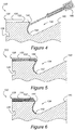
Figure 4 is a fragmentary cross-section of a steel diesel engine piston according to the subject invention illustrating the process of forcibly propelling a spray material of corrosion-resistant and oxidation-resistant composition onto the most vulnerable portions of the piston crown; -
Figure 5 is a cross-sectional view as inFigure 4 , but showing all of the vulnerable areas of the piston crown having been coated with the durable coating material; -
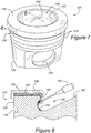
Figure 6 is a fragmentary cross-sectional view of a piston crown as inFigure 5 , but depicting the surfaces after they have been irradiated with a high energy laser beam to increase the density of the coating while simultaneously reforming its microstructure and creating a material bond between the coating and the vulnerable areas of the piston crown; -
Figure 7 is perspective view of a piston according to the subject invention and including a first annular mask applied over the rim section of the piston crown to prevent unwanted irradiation on certain portions of the coated surface; -
Figure 8 is a fragmentary cross-sectional view taken generally along Lines 8-8 inFigure 7 depicting a high energy laser beam irradiating the coating in the bowl region of the piston crown upon which the first mask is applied; -
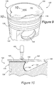
Figure 9 is a perspective view of the piston including a second mask covering the bowl region and the valve pockets so as to expose only the flat, upper rim section of the piston crown; -
Figure 10 is a fragmentary cross-sectional view taken generally along Lines 10-10 inFigure 9 and depicting a laser beam reflecting off of the second mask so as not to irradiate the valve pockets while in the process of irradiating the coating on the rim section; -
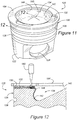
Figure 11 is a perspective view of the piston showing a third mask applied to the top of the piston crown and exposing only the valve pockets so that the coating in this region can be irradiated by the high energy laser beam; and -
Figure 12 is a fragmentary cross-sectional view taken generally along Lines 12-12 inFigure 11 and depicting the high energy laser beam irradiating the coating in the region of the valve pocket to complete the surface preparation of the crown of the piston. - Referring to the figures, wherein like numerals indicate like or corresponding parts throughout the several views, a steel piston for a fuel-injected diesel engine is generally shown at 20 in
Figure 1 . Thepiston 20 is of the type adapted for use in a fuel-injected diesel engine. Thepiston 20 comprises a generallycylindrical skirt portion 22, having a pair of opposing pin bores 24 formed transversely therein. Theskirt 22 guides and supports thepiston 20 as it reciprocates in the cylinder (not shown) of a diesel engine, while the pin bores 24 receive a wrist or gudgeon pin, which attaches to the upper end of a connecting rod (not shown) and, ultimately, to the crank shaft of the engine. A crown, generally indicated at 26, is affixed atop theskirt 22. In the preferred embodiment of this invention, theskirt 22 andcrown 26 are integrally formed of a unitary steel material. The composition of material can be selected from any of the known varieties, including but not limited to the relatively low-cost SAE 4140 H. Instead of the depicted single-piece design, thepiston 20 could be of the so-called "articulating" type, wherein thecrown 26 can pivot slightly relative to theskirt 20 through a common connection about the wrist pin. - The
crown 26 includes a plurality ofring grooves 28 to receive compression and/or oil rings (not shown). Thering grooves 28 are formed into the cylindrical outer, sliding surface of thecrown 26 which, at its upper end, intersects acrown rim 30. Therim 30 is a generally flat, annular region comprising the uppermost, top portion of thepiston 20. Commonly, although not necessarily, one or more valve pockets 32 are formed into therim 30 to provide clearance space for the exhaust and/or intake valve heads 25 (shown in phantom inFigure 3 ) when thepiston 20 is in its top dead center ("TDC") position. - The center inner region of the
crown 26, bounded by therim 30, is known as the bowl, and is generally indicated at 34. Thebowl 34 comprises a combustion-chamber segment formed as a cavity in the top of thepiston crown 26. Amulti-orifice nozzle 36, centered above this extended combustion recess in thecrown 26, injects the fuel in a plurality of radial jets orplumes 38. The configuration of thenozzle 36 and its projectedfuel plume 38 utilizes the depressed and swirling configuration of thebowl 34, combined with the energy in the injected fuel stream to optimize the space in which the air and fuel interact and combustion of the fuel develops. Thebowl 34 may include a peaked or domed center, which falls away toward a recessedtrough 42. Thetrough 42 is a generally annular feature whose upper, ascending face rejoins therim 30. The interface between therim 30 and the ascending face of thetrough 42 comprises a generallyannular lip 44, which may or may not slightly overhang thetrough 42 as shown inFigure 3 . - In the average diesel engine, the plume of injected
fuel 38 initiates at about 5° before top dead center ("BTDC") and continues until about 10° after top dead center ("ATDC") of piston movement. As such, theplume 38, whose trajectory remains generally constant, strafes a surface area of thepiston crown 26 which can be characterized as the plume contact zone. The plume contact zone is, therefore, that portion of the exposed crown surface that is targeted by thefuel injection plume 38 from about 5° BTDC to about 10° ATDC of piston movement within the cylinder, including the upper, ascending surface of thetrough 42, the lip of 44, and therim 30, together with the valve pockets 32. The plume contact zone generally does not include the entire exposed surface area of thebowl 34. Because of the intense heat released by the combustion of the fuel in close proximity to the plume contact zone, the steel composition of thepiston crown 26 in a prior art piston has a tendency to oxidize up to Fe2O3 status. The oxides which result from the transformation no longer adhere to the substrate steel material and are rapidly dislodged as flakes through expansion and contraction processes. Over time but well inside what should otherwise be the useful life of an engine, the expanding eroded areas significantly deteriorate the anti-polluting emission characteristics designed into thecombustion bowl 34 of thepiston 20. Structural integrity can, with time, be severely compromised as well. As perhaps best shown inFigure 2 , these eroded areas will be most pronounced in those regions of thelip 44 coinciding with thespray plumes 38. - Referring now to
Figures 4-12 , an improved piston and method for making and operating an improved piston according to the subject invention is shown. For convenience, reference numbers corresponding to those set forth above are applied to corresponding features of the piston, but with the prefix "1" distinguishing the subject invention from the prior art. - The subject invention is directed toward a
piston 120 having acrown 126 whose surface is modified and enhanced in the plume contact zone so as to better withstand the intense heat released by diesel engine combustion in close vicinity to the surface of thecrown 126.Figures 4 and 5 depict a fragmentary cross-section of thepiston crown 26 as it is sprayed or otherwise treated with a corrosion-resistant and oxidation-resistant composition, such as Amdry 995C, Inconel 718, Stellite 6, nickel-chromium, chromium, or a mixture of these compositions. The corrosion-resistant composition can be applied as a paste-like slurry. Preferably, however, the coating process is carried out as a thermal spray process of either the combustion type or the electric arc type. Such processes have been known by the descriptive term "metalizing." Combustion-type thermal spray processes may include, but are not limited to, powder flame spray, wire/rod flame spray, detonation spray, and high velocity oxygen fuel ("HVOF") spray. Electric arc processes include, but are limited to, arc wire spray and plasma spray. - Using the HVOF spray process as an example, a
pressurized chamber gun 146 uses the combustion of acetylene, hydrogen, propane, propylene, or the like to produce a hot, high-pressure flame. The flame is forced through a DeLaval nozzle to accelerate the carrier gas to supersonic velocities. Feed stock powder can be fed axially into the high-pressure combustion chamber 146 or directly through the side of the nozzle. Feed stock powders may be selected from the group of materials as set forth above. While HVOF is not the only thermal spray process capable of applying a satisfactory coating of corrosion-resistant and oxidation-resistant composition over the vulnerable surfaces of thepiston crown 126, it is nevertheless an acceptable example of the variety of spray processes which can be used. - In addition to the traditional thermal spraying processes described above, it is also possible and included within the intended scope of this invention to utilize a so-called "cold spray" thermal spraying process. According to a cold spray technique, small particles in the 1-50 micron size are accelerated to supersonic velocities and applied to the surface of a work part. In one configuration, helium or nitrogen is injected at high pressure into a pressurized chamber and heated to 300°-700° C. Powder feed stock, such as one of the above-described corrosion-resistant and oxidation-resistant compositions, is introduced into the gas stream, which is not hot enough to melt the particles. The solid powder/gas mixture is then passed through a DeLaval nozzle, where the particles are accelerated to supersonic velocities. The particles impact the substrate with enough kinetic energy to produce a mechanical bond without melting and/or solidification, however, it does not produce a metallurgical bond.
-
Figure 5 represents thepiston crown 126 whose plume contact zone is fully coated with the spray material, forming a durable coating having an as-sprayed microstructure and as-sprayed porosity less than 100% full material density. In other words, the composition of the spray material, after it is fully applied to the relevant surface area of thecrown 126, possesses a characteristic microstructure and a material density which is less than 100% fully dense. Those portions of thebowl 134 which are outside of the plume contact zone are not coated with the corrosion-resistant, oxidation-resistant material. To complete the transition of thispiston crown 126 to the modified robust, long-life piston crown 126 according to the subject invention, a high energy laser beam is then used to irradiate the spray material coating causing a fusion of the coating material, together with the underlying steel substrate of thepiston crown 126. One example of such a laser beam is generated by a so-called High-Power Direct Diode Laser ("HPDL"). The two materials (coating and substrate) intermix under the influence of the laser beam and alloy themselves so as to increase the density of the coating above that of its as-sprayed condition (Figure 5 ), while simultaneously reforming the microstructure of the coating. Furthermore, a material bond between the coating and the crown substrate is established by the subsequent irradiation process. The resulting modifiedpiston crown 126 is depicted inFigure 6 . - Because the surface geometry of a
piston crown 126 over its plume contact zone is complex, numerous passes and orientations of the high energy laser beam are required to fully and evenly irradiate the as-sprayed coating. In order to prevent certain areas of as-sprayed coating from being irradiated at an unintended angle of incidence relative to the laser beam, it is preferred to mask certain portions of the coating both prior to and subsequent to the irradiation process. - Turning now to
Figures 7 and 8 , a first mask is generally indicated at 148. The first mask temporarily covers the coating in the areas of therim 30 and valve pockets 32, while exposing the coating applied in the region of thetrough 142. Thus, while thefirst mask 148 is in place, ahigh energy laser 150 is free to irradiate that portion of thetrough 142 to which the coating material has been applied (i.e., in the plume contact zone). As depicted, the region of thetrough 142 below the focal point of thelaser 150 is shown as having been reformed by the fusing qualities of the laser beam so that the coating material is now alloyed and materially bonded to the substrate steel material. In this example, thelaser 150 is moving its beam in an upwardly ascending path so that as it progresses toward thelip 144, all of the coating material applied to thetrough 142 will eventually be fully irradiated and reformed into a material bond with thesteel piston crown 126. In the preferred embodiment, however, alaser 150 is selected from the type having a rectangular beam of approximately 12 mm x 0.5 mm at focus. The long axis of the beam encompasses thetrough 142 to thelip 144 in a vertical direction, but is fixed in this vertical position. The beam and piston move relative to each other around the circumference, such as by fixing the laser and rotating the piston, so that the long axis of the beam sweeps out the treated area. The resulting fused coating substantially enhances the physical characteristics of thecrown 126, thereby avoiding the problem of oxidation and permitting the continued use of a standard piston steel material, such as SAE 4140 H. Accordingly, the subject invention represents a lower cost solution than other prior art attempts to overcome the problems associated with rim and bowl oxidation. - As the
laser 150 traverses its application area within thebowl 134, thepiston 120 may be rotated and/or thelaser 150 may be rotated so that the entire annular region of coated surface area is adequately irradiated. Should the focal point of thelaser 150 extend above thetrough 142, it will contact thefirst mask 148 and be reflected harmlessly away from thepiston crown 126. This is because thefirst mask 148 is made from a reflective and thermally conductive metallic material, such as polished copper. - Once the
trough 142 region has been adequately irradiated, attention can be directed toward therim 130, which has also been coated by the spray material. However, because the valve pockets 132 are depressed below the surface of therim 130, the focal point of thelaser 150 may not be optimized to effectively irradiate the coating in the region of the valve pockets 132 at the same time as therim 130. Therefore, asecond mask 152 may be used, as shown inFigure 9 . Thesecond mask 152 may also be made from the reflective metallic shield-like material, such as polished copper, and be structured so as to cover the valve pockets 132. The only exposed portions of the spray coatedpiston crown 126 thereby comprise therim surface 130. With the unintended areas effectively shielded by thesecond mask 152, thelaser 150 can be repositioned to irradiate the coated surface of therim 130 as shown inFigure 10 . Again, thepiston 120 and/or thelaser 150 may be rotated to cover theentire rim 130 surface in an efficient manner. Whenever the beam from thelaser 150 strikes thesecond mask 152, as shown inFigure 10 , it is reflected harmlessly away from thecrown 126, and any absorbed heat is quickly dissipated. By this method, the valve pockets 132 are protected from being irradiated by thelaser 150 at a non-ideal setting. Thesecond mask 152 also helps to avoid excessive melting in the corners and along the edges of the valve pockets 132. Furthermore, thetrough portion 142 is protected from subsequent attack by thelaser 150, which might otherwise result in unintended metallurgical reformation of the already irradiated surfaces. - To complete the full irradiation of the as-sprayed coating on the
piston crown 126, athird mask 154 is applied to the top of thepiston crown 126 after thesecond mask 152 has been removed. As depicted inFigure 11 , thethird mask 154 is designed to cover the already irradiatedrim portion 130 and to leave open the area of the valve pockets 132. Thus, the position of thelaser 150 can be reset so that its focal point is gauged to the depth of the valve pockets 132, as shown inFigure 12 . The irradiation process can again take place with relative movement between thecrown 126 and thelaser 150 being accomplished by rotation or other guided relative movement between the two components. As the beam of thelaser 150 passes out of the valve pockets 132 and into the region of therim 130, thethird mask 154 will harmlessly reflect the light energy away from therim surface 130, thereby protecting the already reformed surfaces from further unwanted interaction with the highenergy laser beam 150. Thethird mask 154 further helps to avoid excessive melting in the corners and along the edges of the valve pockets 132. - Although many different types of lasers may be employed to effectively accomplish the irradiating step of the subject invention, a high powered direct diode laser has been found to produce acceptable results.
- It will be appreciated that the first 148, second 152, and third 154 masks can be deployed in sequences other than those described above. Furthermore, fewer than three or more than three masks may be required during the irradiation step to effectively reform the coating material as described herein. Furthermore, while very specific coating materials have been proposed hereinabove for use, these are not the only suitable materials. Rather, any coatings suitable for use in a fusing operation using industrial layers may be employed. For example, as is may be known from the field of gas turbines, various common and proprietary powders may be known to resist high temperature oxidation. Any such known materials may be used, provided that the fused coatings conform to the contours of the plume contact zone without cracking, corrosion, or thermal oxidation. Another advantage of the fused piston crown surface, according to this invention, results in the ability to post-machine, if needed, the irradiated surfaces without chipping or flaking away the sprayed coating. This subject method can be accomplished in high production settings in a fast cycle time and can be demonstrated to be repeatable and amenable to very precise computerized control. The process is highly adaptable to in-line production processes as well.
- Obviously, many modifications and variations of the present invention are possible in light of the above teachings. It is, therefore, to be understood that within the scope of the appended claims, the invention may be practiced otherwise than as specifically described.
Claims (15)
- A method for improving the corrosion resistance of a piston crown for an internal combustion engine, said method comprising the steps of:providing a piston having a crown presenting an exterior crown surface;preparing a coating material consisting essentially of a corrosion-resistant and oxidation-resistant composition;applying the coating material to the piston crown such that the coating material adheres to the crown surface having an as-applied microstructure and an as-applied porosity less than 100% full material density;and irradiating the coating with a high energy laser beam while masking a portion of the coating to prevent irradiation from the laser beam to increase the density of the coating while simultaneously reforming the microstructure and creating a material bond between the coating and the crown surface.
- The method of claim 1 wherein said masking step includes temporarily covering a portion of the crown with a reflective metallic shield.
- The method of claim 2 wherein the piston crown includes a generally annular rim and a concave combustion bowl set below the rim, said step of temporarily covering a portion of the crown including covering one of the rim and the bowl but not the other of the rim and the bowl.
- The method of claim 2 or 3 wherein the piston crown includes at least one valve pocket formed into the rim, said step of temporarily covering a portion of the crown including covering one of the rim and the valve pocket but not the other of the rim and the valve pocket.
- The method of one of the preceding claims wherein said step of forcibly propelling the spray material includes producing a DC electric arc.
- The method of claim 5 wherein said step of producing a DC electric arc includes ionizing an inert gas to produce a high-temperature plasma jet.
- The method of one of the preceding claims wherein said step of irradiating the coating includes employing a high-power direct diode laser.
- The method of one of the preceding claims wherein said step of forcibly propelling the spray material includes applying the spray material to less than all of the exterior crown surface.
- The method of one of the preceding claims wherein said step of providing a piston includes forming the piston from a material composition including a steel alloy.
- The method of one of the preceding claims wherein the exterior crown surface has a plume contact zone comprising that portion of the exterior crown surface to be subsequently targeted by a fuel injection plume from about 5° BTDC to about 10° ATDC of piston movement within a cylinder, and said step of forcibly propelling the spray material includes the step of coating the plume contact zone of the exterior crown surface but not the entire exterior crown surface.
- A use of a steel piston having a crown including a generally annular rim and a concave bowl set below the rim, the interface between the rim and the bowl forming a generally annular lip, the production of the piston including altering the surface composition of the lip of the piston crown by applying a coating material consisting essentially of a corrosion-resistant and oxidation-resistant composition to the lip having an as-applied microstructure and an as-applied porosity less than 100% full material density, and irradiating the coating with a high energy laser beam to increase the density of the coating while simultaneously reforming the microstructure and creating a material bond between the coating and the lip, in a fuel-injected diesel engine, comprising the steps of:providing an engine cylinder having a cylinder head;reciprocating the piston in the cylinder toward and away from the cylinder head;forcibly discharging liquid fuel into the cylinder and toward the lip of the piston crown;combusting the fuel adjacent the lip of the piston crown.
- The use of claim 11 wherein production of said piston further includes altering the surface composition of the rim of the piston crown by forcibly propelling a spray material consisting essentially of a corrosion-resistant and oxidation-resistant composition toward the rim such that the particles of spray material plastically deform upon impact with the rim, and wherein the spray material adheres to the rim as a durable coating having an as-sprayed microstructure and an as-sprayed porosity less than 100% full material density, and irradiating the coating with a high energy laser beam to increase the density of the coating while simultaneously reforming the microstructure and creating a material bond between the coating and the rim.
- The use of claim 11 or 12 wherein production of said piston further includes altering the surface composition of at least a portion of the bowl of the piston crown by forcibly propelling a spray material consisting essentially of a corrosion-resistant and oxidation-resistant composition toward the bowl such that the particles of spray material plastically deform upon impact with the bowl, and wherein the spray material adheres to the rim as a durable coating having an as-sprayed microstructure and an as-sprayed porosity less than 100% full material density, and irradiating the coating with a high energy laser beam to increase the density of the coating while simultaneously reforming the microstructure and creating a material bond between the coating and the bowl.
- A piston for a fuel-injected diesel engine, said piston comprising: a generally cylindrical skirt having a pair of opposing pin bores formed transversely therein; a crown fabricated from a base material composition consisting essentially of steel affixed. atop said skirt, said crown including a generally annular rim and a concave bowl set below said rim, and a generally annular lip along the interface between said rim
and said lip, said rim and at least a portion of said bowl having a bonded surface treatment consisting essentially of an applied corrosion-resistant and oxidation-resistant composition irradiated with a high energy laser beam. - The piston of claim 14 wherein said sprayed-on corrosion-resistant and oxidation-resistant composition of said bonded surface treatment is selected from the group consisting of: Amdry 995C, Inconel 718, Stellite 6, Nickel-Chromium, Chromium, and alloys thereof.
Applications Claiming Priority (2)
| Application Number | Priority Date | Filing Date | Title |
|---|---|---|---|
| US11/431,297 US7458358B2 (en) | 2006-05-10 | 2006-05-10 | Thermal oxidation protective surface for steel pistons |
| PCT/US2007/068633 WO2007134148A2 (en) | 2006-05-10 | 2007-05-10 | Thermal oxidation protective surface for steel pistons |
Publications (3)
| Publication Number | Publication Date |
|---|---|
| EP2021176A2 EP2021176A2 (en) | 2009-02-11 |
| EP2021176A4 EP2021176A4 (en) | 2012-06-13 |
| EP2021176B1 true EP2021176B1 (en) | 2017-07-26 |
Family
ID=38683952
Family Applications (1)
| Application Number | Title | Priority Date | Filing Date |
|---|---|---|---|
| EP07783557.7A Expired - Fee Related EP2021176B1 (en) | 2006-05-10 | 2007-05-10 | Thermal oxidation protective surface for steel pistons |
Country Status (7)
| Country | Link |
|---|---|
| US (1) | US7458358B2 (en) |
| EP (1) | EP2021176B1 (en) |
| JP (1) | JP5300150B2 (en) |
| KR (1) | KR101383098B1 (en) |
| CN (1) | CN101479102B (en) |
| BR (1) | BRPI0713095B1 (en) |
| WO (1) | WO2007134148A2 (en) |
Families Citing this family (53)
| Publication number | Priority date | Publication date | Assignee | Title |
|---|---|---|---|---|
| US20050261241A1 (en) * | 2004-05-19 | 2005-11-24 | Celsus Biopharmaceuticals, Inc. | Use of dermatan sulfates and/or desulfated heparins to treat or prevent heparinoid-induced autoimmune responses |
| DE102005006671A1 (en) * | 2005-02-15 | 2006-08-17 | Ks Kolbenschmidt Gmbh | Protective layer against hot gas combustion in the combustion chamber of an internal combustion engine |
| US20070116889A1 (en) * | 2005-11-18 | 2007-05-24 | Federal Mogul World Wide, Inc. | Laser treatment of metal |
| JP4379503B2 (en) * | 2007-08-13 | 2009-12-09 | トヨタ自動車株式会社 | Piston for internal combustion engine |
| FR2925114A1 (en) * | 2007-12-18 | 2009-06-19 | Inst Francais Du Petrole | INTERNAL COMBUSTION ENGINE WITH SELF-FLAMMING WITH TEMPERATURE STRATIFICATION OF THE CARBIDE MIXTURE AND METHOD OF MAKING SUCH A MIXTURE |
| FR2925604A1 (en) * | 2007-12-19 | 2009-06-26 | Renault Sas | COMBUSTION CHAMBER FOR THERMAL MOTOR WITH DIRECT OVERFLOW INJECTION |
| KR100920685B1 (en) * | 2009-04-06 | 2009-10-09 | 거명터빈주식회사 | Turbine diaphragm out ring inner wall coating method and the turbine diaphragm coated by the method |
| GB0907096D0 (en) * | 2009-04-24 | 2009-06-03 | Isentropic Ltd | Improved piston |
| GB201001562D0 (en) * | 2010-01-29 | 2010-03-17 | Ricardo Uk Ltd | Direct injection diesel |
| KR20120065150A (en) * | 2010-12-10 | 2012-06-20 | 현대자동차주식회사 | Piston haing bowl |
| US8677970B2 (en) | 2011-03-17 | 2014-03-25 | Cummins Intellectual Property, Inc. | Piston for internal combustion engine |
| US9464592B2 (en) * | 2011-04-18 | 2016-10-11 | Achates Power, Inc. | Piston thermal management in an opposed-piston engine |
| US20130025561A1 (en) * | 2011-07-28 | 2013-01-31 | Dieter Gabriel | Bowl rim and root protection for aluminum pistons |
| IN2014CN03942A (en) * | 2011-10-31 | 2015-07-03 | Federal Mogul Corp | |
| US9500285B2 (en) | 2012-03-09 | 2016-11-22 | Mogas Industries, Inc. | High pressure ball valve and packing |
| US9249889B1 (en) | 2012-03-09 | 2016-02-02 | Mogas Industries, Inc. | High pressure ball valve |
| DE102012204947A1 (en) * | 2012-03-28 | 2013-10-02 | Mahle International Gmbh | Method for producing an aluminum piston |
| DE102012103206B4 (en) | 2012-04-13 | 2017-08-03 | Caterpillar Energy Solutions Gmbh | Piston of an internal combustion engine |
| DE102012103212A1 (en) * | 2012-04-13 | 2013-10-17 | Mwm Gmbh | Piston of an internal combustion engine |
| DE102012103195A1 (en) | 2012-04-13 | 2013-10-17 | Mwm Gmbh | Piston of an internal combustion engine |
| US10563569B2 (en) * | 2012-05-16 | 2020-02-18 | Dalian University Of Technology | Diesel combustion system |
| CN102717243A (en) * | 2012-06-18 | 2012-10-10 | 上海交通大学 | Technique for strengthening local surface of engine piston |
| KR101924811B1 (en) * | 2012-08-29 | 2018-12-04 | 현대중공업 주식회사 | Coated exhaust valve spindle of diesel engine using the mixed coating compositions of Inconel-Co-Cr system and the coating method for improving corrosion resistance thereof |
| KR101924810B1 (en) * | 2012-08-29 | 2018-12-04 | 현대중공업 주식회사 | Coated exhaust valve spindle of diesel engine using the mixed coating compositions of Inconel-Ni-Cr system and the coating method for improving corrosion resistance thereof |
| CN105190000B (en) * | 2013-03-05 | 2018-11-20 | 费德罗-莫格尔公司 | Piston and its manufacturing method with anti-carbon coating |
| US20160138516A1 (en) * | 2013-06-14 | 2016-05-19 | Ks Kolbenschmidt Gmbh | Method for producing an oxidation protection layer for a piston for use in internal combustion engines and piston having an oxidation protection layer |
| JP5858007B2 (en) * | 2013-07-01 | 2016-02-10 | トヨタ自動車株式会社 | Overlaying method for valve seat and manufacturing method of cylinder head |
| DE102013221102A1 (en) | 2013-10-17 | 2015-05-07 | Mahle International Gmbh | Steel piston for an internal combustion engine and method for its production |
| EP2865479A1 (en) * | 2013-10-22 | 2015-04-29 | Siemens Aktiengesellschaft | Method and system for generating a component using thermal spraying and laser fusing |
| US9765727B2 (en) | 2014-03-03 | 2017-09-19 | Federal-Mogul Llc | One-piece piston featuring additive machining produced combustion bowl rim and cooling gallery |
| JP6260492B2 (en) * | 2014-08-11 | 2018-01-17 | トヨタ自動車株式会社 | Manufacturing method of piston for direct injection engine |
| WO2016028760A1 (en) | 2014-08-18 | 2016-02-25 | Woodward, Inc. | Torch igniter |
| DE102014018256A1 (en) * | 2014-12-11 | 2016-06-16 | Mahle International Gmbh | Piston for an internal combustion engine |
| US20160169152A1 (en) * | 2014-12-11 | 2016-06-16 | Caterpillar Inc. | Engine Piston |
| US10138840B2 (en) | 2015-02-20 | 2018-11-27 | Ford Global Technologies, Llc | PTWA coating on pistons and/or cylinder heads and/or cylinder bores |
| DE102015221960A1 (en) * | 2015-11-09 | 2017-05-11 | Federal-Mogul Nürnberg GmbH | Protective layer against the oxidation of the piston of an internal combustion engine |
| US10876475B2 (en) | 2015-11-20 | 2020-12-29 | Tenneco Inc. | Steel piston crown and/or combustion engine components with dynamic thermal insulation coating and method of making and using such a coating |
| US10519854B2 (en) | 2015-11-20 | 2019-12-31 | Tenneco Inc. | Thermally insulated engine components and method of making using a ceramic coating |
| US10578050B2 (en) | 2015-11-20 | 2020-03-03 | Tenneco Inc. | Thermally insulated steel piston crown and method of making using a ceramic coating |
| US10578014B2 (en) | 2015-11-20 | 2020-03-03 | Tenneco Inc. | Combustion engine components with dynamic thermal insulation coating and method of making and using such a coating |
| CN105484892A (en) * | 2015-12-02 | 2016-04-13 | 湖南江滨机器(集团)有限责任公司 | Piston, engine and piston manufacturing method |
| JP6288116B2 (en) * | 2016-01-21 | 2018-03-07 | トヨタ自動車株式会社 | Cylinder head manufacturing method |
| JP6384493B2 (en) * | 2016-01-21 | 2018-09-05 | トヨタ自動車株式会社 | Cylinder head manufacturing method |
| CN109072397B (en) | 2016-04-08 | 2021-08-31 | 沃尔沃卡车集团 | Piston for a cylinder of an internal combustion engine |
| US20170355018A1 (en) | 2016-06-09 | 2017-12-14 | Hamilton Sundstrand Corporation | Powder deposition for additive manufacturing |
| CN106435673A (en) * | 2016-12-22 | 2017-02-22 | 日照金港活塞有限公司 | Preparation technology of thermal insulation coating on internal combustion engine forging steel piston top |
| US20180238264A1 (en) * | 2017-02-19 | 2018-08-23 | GM Global Technology Operations LLC | Diesel piston with stepped bowl |
| CN107218152A (en) * | 2017-07-27 | 2017-09-29 | 叶明� | Compression ratio plug structure applied to diesel cetane-number measuring machine |
| US10471554B2 (en) | 2017-08-22 | 2019-11-12 | Caterpillar Inc. | Fuel injector bore repair |
| JP2019143497A (en) * | 2018-02-16 | 2019-08-29 | トヨタ自動車株式会社 | Compression self-ignition type internal combustion engine |
| EP3864275A1 (en) * | 2018-10-08 | 2021-08-18 | Federal-Mogul Motorparts LLC | Detonation resistant piston |
| US11421601B2 (en) | 2019-03-28 | 2022-08-23 | Woodward, Inc. | Second stage combustion for igniter |
| US11719184B1 (en) * | 2022-01-21 | 2023-08-08 | Tenneco Inc. | Piston with engineered crown coating and method of manufacturing |
Family Cites Families (54)
| Publication number | Priority date | Publication date | Assignee | Title |
|---|---|---|---|---|
| US3892207A (en) * | 1970-01-23 | 1975-07-01 | Carl A Weise | Internal combustion engine |
| JPS5948873B2 (en) * | 1980-05-14 | 1984-11-29 | ペルメレック電極株式会社 | Method for manufacturing electrode substrate or electrode provided with corrosion-resistant coating |
| US4434189A (en) * | 1982-03-15 | 1984-02-28 | The United States Of America As Represented By The Adminstrator Of The National Aeronautics And Space Administration | Method and apparatus for coating substrates using a laser |
| JPS61126360A (en) * | 1984-11-26 | 1986-06-13 | Mitsubishi Heavy Ind Ltd | Forming method of flame sprayed film on piston |
| JPS61270335A (en) | 1985-05-24 | 1986-11-29 | Toyota Motor Corp | Build-up valve for internal combustion engine |
| JPS6256562A (en) * | 1985-09-04 | 1987-03-12 | Toyota Motor Corp | Production of piston thermal sprayed with ceramics |
| US4708752A (en) | 1986-03-24 | 1987-11-24 | Smith International, Inc. | Process for laser hardening drilling bit cones having hard cutter inserts placed therein |
| US4781770A (en) | 1986-03-24 | 1988-11-01 | Smith International, Inc. | Process for laser hardfacing drill bit cones having hard cutter inserts |
| DE3773258D1 (en) | 1986-05-18 | 1991-10-31 | Daido Steel Co Ltd | WEAR-RESISTANT ITEMS MADE OF TITANIUM OR TITANIUM ALLOY. |
| JPH0684548B2 (en) | 1986-09-19 | 1994-10-26 | 吉田工業株式会社 | Coated metal body with highly corrosion-resistant amorphous surface layer and its preparation method |
| JPS63143364A (en) * | 1986-12-08 | 1988-06-15 | Mazda Motor Corp | Manufacture of piston of internal combustion engine |
| JPH0698506B2 (en) | 1986-12-08 | 1994-12-07 | トヨタ自動車株式会社 | Method for forming dispersed alloy layer on metal substrate |
| US4960643A (en) * | 1987-03-31 | 1990-10-02 | Lemelson Jerome H | Composite synthetic materials |
| JPH0649888B2 (en) | 1989-03-24 | 1994-06-29 | 新日本製鐵株式会社 | Method for producing surface-coated metal |
| EP0438971B1 (en) * | 1990-01-22 | 1994-05-11 | Sulzer Innotec Ag | Coated metallic substrate |
| US5014605A (en) * | 1990-02-21 | 1991-05-14 | Briggs & Stratton Corporation | Magnesium piston coated with a fuel ingition products adhesive |
| CA2037660C (en) | 1990-03-07 | 1997-08-19 | Tadashi Kamimura | Methods of modifying surface qualities of metallic articles and apparatuses therefor |
| DK0521821T3 (en) | 1991-07-04 | 1996-08-26 | New Sulzer Diesel Ag | Exhaust valve for a diesel combustion engine and method of manufacturing the valve |
| JPH0525655A (en) * | 1991-07-15 | 1993-02-02 | Komatsu Ltd | Method for hardening surface of aluminum base metal and surface hardened aluminum base member |
| JP3148340B2 (en) | 1991-08-27 | 2001-03-19 | 福田金属箔粉工業株式会社 | High-toughness chromium-based alloy for hard facing, powder thereof, and engine valve for automobile coated with the alloy |
| US5194304A (en) * | 1992-07-07 | 1993-03-16 | Ford Motor Company | Thermally spraying metal/solid libricant composites using wire feedstock |
| US5554415A (en) * | 1994-01-18 | 1996-09-10 | Qqc, Inc. | Substrate coating techniques, including fabricating materials on a surface of a substrate |
| DK172987B1 (en) | 1994-12-13 | 1999-11-01 | Man B & W Diesel As | Cylinder element, nickel-based alloy and application of the alloy |
| US5640667A (en) | 1995-11-27 | 1997-06-17 | Board Of Regents, The University Of Texas System | Laser-directed fabrication of full-density metal articles using hot isostatic processing |
| WO1997026388A2 (en) * | 1996-01-15 | 1997-07-24 | The University Of Tennessee Research Corporation | Laser induced surfaces |
| US6350326B1 (en) | 1996-01-15 | 2002-02-26 | The University Of Tennessee Research Corporation | Method for practicing a feedback controlled laser induced surface modification |
| US5985056A (en) | 1996-01-15 | 1999-11-16 | The University Of Tennessee Research Corporation | Method for laser induced improvement of surfaces |
| US5773078A (en) | 1996-06-24 | 1998-06-30 | General Electric Company | Method for depositing zirconium oxide on a substrate |
| US6001426A (en) * | 1996-07-25 | 1999-12-14 | Utron Inc. | High velocity pulsed wire-arc spray |
| US5715270A (en) * | 1996-09-27 | 1998-02-03 | Mcdonnell Douglas Corporation | High efficiency, high power direct diode laser systems and methods therefor |
| US5759932A (en) | 1996-11-08 | 1998-06-02 | General Electric Company | Coating composition for metal-based substrates, and related processes |
| DE19740205B4 (en) | 1997-09-12 | 2004-11-25 | Fraunhofer-Gesellschaft zur Förderung der angewandten Forschung e.V. | Process for applying a coating by means of plasma spraying |
| JP3491811B2 (en) * | 1997-10-31 | 2004-01-26 | スズキ株式会社 | Sliding member and piston |
| US6127046A (en) * | 1997-12-04 | 2000-10-03 | Cummins Engine Company, Inc. | Formation of a graphite-free surface in a ferrous material to produce an improved intermetallic bond |
| US6016227A (en) | 1998-07-31 | 2000-01-18 | The University Of Tennessee Research Corporation | Apparatus and method for producing an improved laser beam |
| US5934174A (en) * | 1998-10-02 | 1999-08-10 | Cummins Engine Company, Inc. | Lightweight articulated piston head and method of making the piston head |
| WO2000049195A1 (en) * | 1999-02-19 | 2000-08-24 | Volkswagen Aktiengesellschaft | Method for machining a component surface |
| CN1192121C (en) * | 1999-02-19 | 2005-03-09 | 大众汽车有限公司 | Method and device for treating a component surface |
| US6294225B1 (en) | 1999-05-10 | 2001-09-25 | The University Of Tennessee Research Corporation | Method for improving the wear and corrosion resistance of material transport trailer surfaces |
| US6173886B1 (en) | 1999-05-24 | 2001-01-16 | The University Of Tennessee Research Corportion | Method for joining dissimilar metals or alloys |
| US6299707B1 (en) | 1999-05-24 | 2001-10-09 | The University Of Tennessee Research Corporation | Method for increasing the wear resistance in an aluminum cylinder bore |
| US6284067B1 (en) | 1999-07-02 | 2001-09-04 | The University Of Tennessee Research Corporation | Method for producing alloyed bands or strips on pistons for internal combustion engines |
| JP2001098989A (en) * | 1999-09-29 | 2001-04-10 | Mazda Motor Corp | Controller for engine, and abnormality diagnostic device therefor |
| US6328026B1 (en) | 1999-10-13 | 2001-12-11 | The University Of Tennessee Research Corporation | Method for increasing wear resistance in an engine cylinder bore and improved automotive engine |
| US6229111B1 (en) | 1999-10-13 | 2001-05-08 | The University Of Tennessee Research Corporation | Method for laser/plasma surface alloying |
| DE10029810A1 (en) * | 2000-06-16 | 2001-12-20 | Mahle Gmbh | Piston for diesel engine; has steel base with combustion mould and has thermal sprayed NiCrAl, CoCrAl or FeCrAl alloy coating, which is thicker at mould edge |
| GB2365507B (en) * | 2000-08-02 | 2004-09-15 | Federal Mogul Technology Ltd | Engine piston and manufacture |
| US6936118B2 (en) * | 2001-08-07 | 2005-08-30 | Northeastern University | Process of forming a composite coating on a substrate |
| US6602550B1 (en) * | 2001-09-26 | 2003-08-05 | Arapahoe Holdings, Llc | Method for localized surface treatment of metal component by diffusion alloying |
| JP2003278597A (en) * | 2002-03-20 | 2003-10-02 | Mitsubishi Heavy Ind Ltd | Engine member, exhaust vale, piston crown and internal combustion engine |
| US6818532B2 (en) * | 2002-04-09 | 2004-11-16 | Oriol, Inc. | Method of etching substrates |
| JP2003343351A (en) * | 2002-05-24 | 2003-12-03 | Hitachi Unisia Automotive Ltd | Piston of internal combustion engine |
| US6749894B2 (en) * | 2002-06-28 | 2004-06-15 | Surface Engineered Products Corporation | Corrosion-resistant coatings for steel tubes |
| US6973723B2 (en) * | 2003-01-08 | 2005-12-13 | International Engine Intellectual Property Company, Llc | Piston formed by powder metallurgical methods |
-
2006
- 2006-05-10 US US11/431,297 patent/US7458358B2/en active Active
-
2007
- 2007-05-10 CN CN2007800239237A patent/CN101479102B/en active Active
- 2007-05-10 KR KR1020087029574A patent/KR101383098B1/en active IP Right Grant
- 2007-05-10 BR BRPI0713095A patent/BRPI0713095B1/en not_active IP Right Cessation
- 2007-05-10 JP JP2009510169A patent/JP5300150B2/en not_active Expired - Fee Related
- 2007-05-10 EP EP07783557.7A patent/EP2021176B1/en not_active Expired - Fee Related
- 2007-05-10 WO PCT/US2007/068633 patent/WO2007134148A2/en active Application Filing
Non-Patent Citations (1)
| Title |
|---|
| None * |
Also Published As
| Publication number | Publication date |
|---|---|
| US7458358B2 (en) | 2008-12-02 |
| WO2007134148A3 (en) | 2008-12-04 |
| JP5300150B2 (en) | 2013-09-25 |
| US20070261663A1 (en) | 2007-11-15 |
| CN101479102A (en) | 2009-07-08 |
| CN101479102B (en) | 2013-12-11 |
| JP2009536712A (en) | 2009-10-15 |
| KR101383098B1 (en) | 2014-04-08 |
| BRPI0713095B1 (en) | 2018-10-16 |
| KR20090026273A (en) | 2009-03-12 |
| WO2007134148A2 (en) | 2007-11-22 |
| BRPI0713095A2 (en) | 2012-10-16 |
| EP2021176A2 (en) | 2009-02-11 |
| EP2021176A4 (en) | 2012-06-13 |
Similar Documents
| Publication | Publication Date | Title |
|---|---|---|
| EP2021176B1 (en) | Thermal oxidation protective surface for steel pistons | |
| JP2009536712A5 (en) | ||
| US6047539A (en) | Method of protecting gas turbine combustor components against water erosion and hot corrosion | |
| JP3183724U (en) | Piston with piston ring groove coated with sprayed layer | |
| CN105904068B (en) | PTWA coating on pistons and/or cylinder heads and/or cylinder bores | |
| US20130055993A1 (en) | Cylinder liner with a thermal barrier coating | |
| CN108495946A (en) | Heat-insulated engine components and the manufacturing method using ceramic coating | |
| JP2018534479A (en) | Fabrication method using insulated steel piston crown and ceramic coating | |
| KR20030005413A (en) | Diesel engine piston | |
| GB2383833A (en) | Piston with a ceramic reinforced ring groove | |
| SG153818A1 (en) | Smooth outer coating for combustor components and coating method therefor | |
| CN110607495B (en) | Plasma spraying method for coating cylinder sleeve working surface of cylinder crankcase of internal combustion engine | |
| CN107151777B (en) | The hot-spraying coating manufacturing process that sprayed on material and bombardment particle phase are implemented in combination with | |
| CN102080601A (en) | Pilot burner of a gas turbine engine, combustor, and gas turbine engine | |
| CN109371350A (en) | A kind of micro- molten and compound method for preparing WC-12Co coating of supersonic flame spraying of laser | |
| USH1869H (en) | Valve train components having an oxidation and corrosion-resistant thermal spray coating | |
| JP6722585B2 (en) | Integrated sintering method for microcracking and erosion resistance of heat shields | |
| JPS61126360A (en) | Forming method of flame sprayed film on piston | |
| US11719184B1 (en) | Piston with engineered crown coating and method of manufacturing | |
| Fauchais et al. | Combustion Spraying Systems | |
| JPH0734215A (en) | Plasma torch | |
| JP2018009554A (en) | Cylinder head of engine |
Legal Events
| Date | Code | Title | Description |
|---|---|---|---|
| PUAI | Public reference made under article 153(3) epc to a published international application that has entered the european phase |
Free format text: ORIGINAL CODE: 0009012 |
|
| 17P | Request for examination filed |
Effective date: 20081127 |
|
| AK | Designated contracting states |
Kind code of ref document: A2 Designated state(s): AT BE BG CH CY CZ DE DK EE ES FI FR GB GR HU IE IS IT LI LT LU LV MC MT NL PL PT RO SE SI SK TR |
|
| AX | Request for extension of the european patent |
Extension state: AL BA HR MK RS |
|
| DAX | Request for extension of the european patent (deleted) | ||
| RBV | Designated contracting states (corrected) |
Designated state(s): DE FR IT |
|
| A4 | Supplementary search report drawn up and despatched |
Effective date: 20120516 |
|
| RIC1 | Information provided on ipc code assigned before grant |
Ipc: F02B 23/06 20060101ALI20120510BHEP Ipc: C23C 4/18 20060101ALI20120510BHEP Ipc: B32B 15/18 20060101AFI20120510BHEP Ipc: F02F 3/14 20060101ALI20120510BHEP Ipc: F16J 1/01 20060101ALI20120510BHEP Ipc: B23K 26/34 20060101ALI20120510BHEP Ipc: F02F 3/12 20060101ALI20120510BHEP |
|
| GRAP | Despatch of communication of intention to grant a patent |
Free format text: ORIGINAL CODE: EPIDOSNIGR1 |
|
| INTG | Intention to grant announced |
Effective date: 20170315 |
|
| GRAS | Grant fee paid |
Free format text: ORIGINAL CODE: EPIDOSNIGR3 |
|
| GRAA | (expected) grant |
Free format text: ORIGINAL CODE: 0009210 |
|
| AK | Designated contracting states |
Kind code of ref document: B1 Designated state(s): DE FR IT |
|
| REG | Reference to a national code |
Ref country code: DE Ref legal event code: R096 Ref document number: 602007051767 Country of ref document: DE |
|
| REG | Reference to a national code |
Ref country code: FR Ref legal event code: PLFP Year of fee payment: 12 |
|
| REG | Reference to a national code |
Ref country code: DE Ref legal event code: R097 Ref document number: 602007051767 Country of ref document: DE |
|
| PLBE | No opposition filed within time limit |
Free format text: ORIGINAL CODE: 0009261 |
|
| STAA | Information on the status of an ep patent application or granted ep patent |
Free format text: STATUS: NO OPPOSITION FILED WITHIN TIME LIMIT |
|
| REG | Reference to a national code |
Ref country code: DE Ref legal event code: R082 Ref document number: 602007051767 Country of ref document: DE Representative=s name: HOFFMANN - EITLE PATENT- UND RECHTSANWAELTE PA, DE Ref country code: DE Ref legal event code: R081 Ref document number: 602007051767 Country of ref document: DE Owner name: FEDERAL-MOGUL LLC (N. D. GES. D. STAATES DELAW, US Free format text: FORMER OWNER: FEDERAL-MOGUL CORPORATION, SOUTHFIELD, MICH., US |
|
| 26N | No opposition filed |
Effective date: 20180430 |
|
| PGFP | Annual fee paid to national office [announced via postgrant information from national office to epo] |
Ref country code: IT Payment date: 20190419 Year of fee payment: 9 |
|
| PGFP | Annual fee paid to national office [announced via postgrant information from national office to epo] |
Ref country code: FR Payment date: 20190417 Year of fee payment: 13 |
|
| PGFP | Annual fee paid to national office [announced via postgrant information from national office to epo] |
Ref country code: DE Payment date: 20200417 Year of fee payment: 14 |
|
| PG25 | Lapsed in a contracting state [announced via postgrant information from national office to epo] |
Ref country code: FR Free format text: LAPSE BECAUSE OF NON-PAYMENT OF DUE FEES Effective date: 20200531 |
|
| PG25 | Lapsed in a contracting state [announced via postgrant information from national office to epo] |
Ref country code: IT Free format text: LAPSE BECAUSE OF NON-PAYMENT OF DUE FEES Effective date: 20200510 |
|
| REG | Reference to a national code |
Ref country code: DE Ref legal event code: R119 Ref document number: 602007051767 Country of ref document: DE |
|
| PG25 | Lapsed in a contracting state [announced via postgrant information from national office to epo] |
Ref country code: DE Free format text: LAPSE BECAUSE OF NON-PAYMENT OF DUE FEES Effective date: 20211201 |