EP2020537A2 - Shifting unit for an electronically controlled transmission - Google Patents
Shifting unit for an electronically controlled transmission Download PDFInfo
- Publication number
- EP2020537A2 EP2020537A2 EP08012562A EP08012562A EP2020537A2 EP 2020537 A2 EP2020537 A2 EP 2020537A2 EP 08012562 A EP08012562 A EP 08012562A EP 08012562 A EP08012562 A EP 08012562A EP 2020537 A2 EP2020537 A2 EP 2020537A2
- Authority
- EP
- European Patent Office
- Prior art keywords
- selector lever
- switching unit
- unit according
- positions
- selector
- Prior art date
- Legal status (The legal status is an assumption and is not a legal conclusion. Google has not performed a legal analysis and makes no representation as to the accuracy of the status listed.)
- Withdrawn
Links
Images


Classifications
-
- F—MECHANICAL ENGINEERING; LIGHTING; HEATING; WEAPONS; BLASTING
- F16—ENGINEERING ELEMENTS AND UNITS; GENERAL MEASURES FOR PRODUCING AND MAINTAINING EFFECTIVE FUNCTIONING OF MACHINES OR INSTALLATIONS; THERMAL INSULATION IN GENERAL
- F16H—GEARING
- F16H59/00—Control inputs to control units of change-speed-, or reversing-gearings for conveying rotary motion
- F16H59/02—Selector apparatus
- F16H59/0204—Selector apparatus for automatic transmissions with means for range selection and manual shifting, e.g. range selector with tiptronic
-
- F—MECHANICAL ENGINEERING; LIGHTING; HEATING; WEAPONS; BLASTING
- F16—ENGINEERING ELEMENTS AND UNITS; GENERAL MEASURES FOR PRODUCING AND MAINTAINING EFFECTIVE FUNCTIONING OF MACHINES OR INSTALLATIONS; THERMAL INSULATION IN GENERAL
- F16H—GEARING
- F16H59/00—Control inputs to control units of change-speed-, or reversing-gearings for conveying rotary motion
- F16H59/02—Selector apparatus
- F16H59/08—Range selector apparatus
- F16H59/10—Range selector apparatus comprising levers
-
- F—MECHANICAL ENGINEERING; LIGHTING; HEATING; WEAPONS; BLASTING
- F16—ENGINEERING ELEMENTS AND UNITS; GENERAL MEASURES FOR PRODUCING AND MAINTAINING EFFECTIVE FUNCTIONING OF MACHINES OR INSTALLATIONS; THERMAL INSULATION IN GENERAL
- F16H—GEARING
- F16H61/00—Control functions within control units of change-speed- or reversing-gearings for conveying rotary motion ; Control of exclusively fluid gearing, friction gearing, gearings with endless flexible members or other particular types of gearing
- F16H61/24—Providing feel, e.g. to enable selection
-
- F—MECHANICAL ENGINEERING; LIGHTING; HEATING; WEAPONS; BLASTING
- F16—ENGINEERING ELEMENTS AND UNITS; GENERAL MEASURES FOR PRODUCING AND MAINTAINING EFFECTIVE FUNCTIONING OF MACHINES OR INSTALLATIONS; THERMAL INSULATION IN GENERAL
- F16H—GEARING
- F16H59/00—Control inputs to control units of change-speed-, or reversing-gearings for conveying rotary motion
- F16H59/02—Selector apparatus
- F16H2059/0221—Selector apparatus for selecting modes, i.e. input device
-
- F—MECHANICAL ENGINEERING; LIGHTING; HEATING; WEAPONS; BLASTING
- F16—ENGINEERING ELEMENTS AND UNITS; GENERAL MEASURES FOR PRODUCING AND MAINTAINING EFFECTIVE FUNCTIONING OF MACHINES OR INSTALLATIONS; THERMAL INSULATION IN GENERAL
- F16H—GEARING
- F16H59/00—Control inputs to control units of change-speed-, or reversing-gearings for conveying rotary motion
- F16H59/02—Selector apparatus
- F16H2059/0239—Up- and down-shift or range or mode selection by repeated movement
-
- F—MECHANICAL ENGINEERING; LIGHTING; HEATING; WEAPONS; BLASTING
- F16—ENGINEERING ELEMENTS AND UNITS; GENERAL MEASURES FOR PRODUCING AND MAINTAINING EFFECTIVE FUNCTIONING OF MACHINES OR INSTALLATIONS; THERMAL INSULATION IN GENERAL
- F16H—GEARING
- F16H59/00—Control inputs to control units of change-speed-, or reversing-gearings for conveying rotary motion
- F16H59/02—Selector apparatus
- F16H2059/0252—Selector apparatus with means for initiating skip or double gear shifts, e.g. by moving selection lever beyond a threshold
-
- F—MECHANICAL ENGINEERING; LIGHTING; HEATING; WEAPONS; BLASTING
- F16—ENGINEERING ELEMENTS AND UNITS; GENERAL MEASURES FOR PRODUCING AND MAINTAINING EFFECTIVE FUNCTIONING OF MACHINES OR INSTALLATIONS; THERMAL INSULATION IN GENERAL
- F16H—GEARING
- F16H59/00—Control inputs to control units of change-speed-, or reversing-gearings for conveying rotary motion
- F16H59/02—Selector apparatus
- F16H2059/0295—Selector apparatus with mechanisms to return lever to neutral or datum position, e.g. by return springs
-
- F—MECHANICAL ENGINEERING; LIGHTING; HEATING; WEAPONS; BLASTING
- F16—ENGINEERING ELEMENTS AND UNITS; GENERAL MEASURES FOR PRODUCING AND MAINTAINING EFFECTIVE FUNCTIONING OF MACHINES OR INSTALLATIONS; THERMAL INSULATION IN GENERAL
- F16H—GEARING
- F16H61/00—Control functions within control units of change-speed- or reversing-gearings for conveying rotary motion ; Control of exclusively fluid gearing, friction gearing, gearings with endless flexible members or other particular types of gearing
- F16H61/24—Providing feel, e.g. to enable selection
- F16H2061/247—Detents for range selectors
-
- F—MECHANICAL ENGINEERING; LIGHTING; HEATING; WEAPONS; BLASTING
- F16—ENGINEERING ELEMENTS AND UNITS; GENERAL MEASURES FOR PRODUCING AND MAINTAINING EFFECTIVE FUNCTIONING OF MACHINES OR INSTALLATIONS; THERMAL INSULATION IN GENERAL
- F16H—GEARING
- F16H63/00—Control outputs from the control unit to change-speed- or reversing-gearings for conveying rotary motion or to other devices than the final output mechanism
- F16H63/40—Control outputs from the control unit to change-speed- or reversing-gearings for conveying rotary motion or to other devices than the final output mechanism comprising signals other than signals for actuating the final output mechanisms
- F16H63/42—Ratio indicator devices
- F16H2063/423—Range indicators for automatic transmissions, e.g. showing selected range or mode
Definitions
- the invention relates to a switching unit for an electronically shifted transmission, comprising a selector lever, which is movable for selecting different gear stages to be inserted in the transmission side in different selection positions.
- the invention is therefore based on the problem to provide a switching unit, which allows the possibility of easy insertion of the P-speed and easy for the driver to use.
- a switching unit of the type mentioned that at least four different speed levels can be selected via the selector lever, wherein the selector lever is movable out of a stable basic position in two opposite directions along which at least three not latched, Selector positions defined by a pressure point are realized, from which the selector lever can be automatically reset to the basic position.
- a total of at least seven separate positions are realized, which make it possible to select the four speed levels PRND can.
- the selector lever itself when not actively moved by the driver, is always in a home position, in which it is automatically returned when moved out of it in one of the selector positions that follow it in that direction.
- the selector positions are assigned to variable speed steps as a function of the variable speed level assigned to the basic position. D.
- the switching unit according to the invention offers a number of advantages.
- the P-drive stage can be integrated into the shift pattern, specifically in the PRND sequence known per se.
- the driver the circuit diagram known to him for a long time even with electronically connected transmissions or electronic switching units.
- the monostable design in which therefore the selector lever is always in the basic position, has no "pointing effect", in contrast to known latched selector levers, which thus remain in the respective selection position.
- the selector lever or the basic position is when restarting automatically assigned the P-speed, starting from which then the selector lever can be moved in accordance with the predetermined shift pattern for selecting a different speed level. Even with a system failure, the selector lever is always in the same basic position, the driver can be warned by a display or other display.
- the selector lever can be moved against a mechanical return element in the respective direction.
- the mechanical restoring element is preferably a spring, which is tensioned accordingly when moving from the basic position into the first, second or third selection position. It is also conceivable to integrate the mechanical return element quasi in the selector lever, via a mechanical guide of the lever on a backdrop mitels a spring-loaded roller, which runs sprung on the backdrop. The scenery and the spring are designed in such a way that the spring, which loads the roller, can always bring the lever to its original position under the return of the roller on the gate.
- the selector lever can also be reset via an electrical or electro-mechanical or hydraulic or pneumatic return means.
- an electromagnet which is driven by moving the selector lever in a specific selection position and detecting the same via a suitable sensor to retract the selector lever back to the basic position.
- hydraulic or pneumatic return means for example in the form of suitable actuating cylinder, are conceivable.
- the individual pressure points themselves which are realized over the entire movement length, are expediently realized via a mechanical guidance of the selector lever, in particular a slotted guide, on or in which the selector lever slides.
- a guide has, for example, a corrugated guide profile on which the lower end of the pivotable selector lever runs, for example via a spring-loaded roller.
- Each selection position can be realized, for example, via a trough into which the guide roller enters, which can be felt haptically. To move out of the sink must be worked against the rising profile again, which is also tactile.
- the automatic return of the lever can also be done as described on the lever side integrated spring-loaded roller itself, in which case the backdrop has no sinks.
- the switching unit is expediently assigned a switching means via which the functionality of the switching unit can be reversibly switched to a manual tap-change of individual gears.
- the driver can therefore by operating a switching means, such as a button on the steering wheel, change the functionality of the switching unit from the conventional functionality, in the context of which the known driving levels PRND are selectable, to a manual tap-change, in the context of which the selector lever starting from Move up or down in the home position by moving forward to the next pressure point or in the opposite direction until the next pressure point.
- a switching means such as a button on the steering wheel
- the gear can be up or downshifted. That is, when the selector lever is pulled back by the driver in the first pressure point, is shifted down by a first gear, the selector lever is pulled further into the second pressure point, a second gear is downshifted.
- the third pressure point following in the respective direction is used as the third switching point. This allows a much faster switching in the context of the jog dial than conventional, where the selector lever for shifting each a gear from the basic position to the switching position must be moved and released again, for switching another gear, this process is carried out again.
- the driver pulls the selector lever only two or three pressure points, the transmission follows immediately.
- the switching unit according to the invention also from a first shift gate, along which the selector lever is movable to switch the speed levels, branch off a second shift gate, in which the Selector lever for a manual tap-shift individual gears is movable. So if you want to switch to jogging, so the driver has to move the selector lever again starting from the basic position, for example, a short distance to the right in the second shift gate, where then the jogging is given.
- the selector lever starting from a basic position in this second shift gate is movable in two opposite directions, along which at least two non-latched, selected via a pressure point selection positions are realized from which the selector lever automatically reset to the basic position wherein, starting from the home position when moving in at least two consecutive pressure points in one direction upon reaching each pressure point, a gear is up or downshiftable.
- a separate second jogging Kunststoffgasse can be achieved by realizing two or more pressure point a much faster switching, because the selector lever, for example, to downshift two gears only once to pull in the two successive pressure points.
- the selector lever in the basic position in which it is always located as described, the P-speed assigned, for example, at a restart of the car the following driving steps R, N and D can only by moving in one direction, namely by moving to the rear pulling the selector lever can be selected, as a result of the realization of the rigid circuit diagram PRND.
- the selector lever movement can basically be mechanically blocked from the basic position or from or to any desired selection position. D. h., About this blocking possibility, the selector lever can be moved in any direction only as far as the next respective pressure point or the next following dialing position is assigned a selectable gear at all.
- All other selector lever positions are mechanically locked, including, for example, a mechanical or electromechanical locking element is provided, for.
- a mechanical or electromechanical locking element is provided, for.
- an electromagnet which provides a pawl or the like, which engages in a corresponding guide or locking gate, the corresponding locking receptacles for the pawl, and prevents a corresponding movement of the selector lever.
- the selector lever is always movable in principle, that is also in a selectable position can be brought, which is associated with no gear, but in this case then inevitably no speed control circuit.
- the driver has not switched over to the optional manual tipping circuit to which all three pressure points or selection positions are permissible. If, for example, only two pressure points or selection positions are assigned in each direction, then the respective third position can also be mechanically locked, for example, or no switching takes place in this despite selector lever movement.
- a display means is expediently provided on the switching unit, optionally an external indicating means may also be provided here.
- the basic driving sequence PRND can be specified, for example, as a permanently installed representation on the switching unit for the basic orientation of the driver, so that he knows in which direction he has to move the lever starting from the basic position driving position shown.
- the display means may also have a plurality of display positions corresponding to the number and preferably the position at basic and selection positions for the engaged and the selectable driving steps. In this embodiment of the invention, therefore, a maximum of seven display positions are given, on which the driving steps that can be selected there in each case can be displayed. Depending on which gear position is assigned to the basic position, ultimately the display changes constantly, but there are a maximum of four displays that just indicate the ever selectable driving levels P-R-N-D. Display positions that are assigned to dialing items without the ability to select a speed level or that have the blocked dialing positions assigned are not in operation.
- either a separate switching element can be provided for this purpose, which can be activated, for example, only if the previously selected gear is the D-speed, so therefore the selector lever basic position is assigned. It would also be conceivable, however, for the selector lever, starting from the basic position, to be able to be moved into a further selector position which branches off to the left, for example, but in which case it is then optionally locked. This branch is, if a manual jogging circuit is provided with a separate second shift gate, opposite to the direction of movement in the second shift gate.
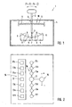
- Fig. 1 shows a switching unit 1 according to the invention, comprising a selector lever 2 which is pivotable about a pivot axis 3. It is associated with a mechanical guide 5 in the form of a slotted guide in a housing 4 of the switching unit 1, along which it runs over a loaded via a spring 6 running element 7.
- the guide 5 has seven recesses 9, each of which produces pressure points 8.
- the selector lever 2 itself is against a return element 10, here formed by way of example two springs 11, starting from the in Fig. 1 shown basic position, in which he is in the middle of the seven excellent selection positions, movable.
- This middle selection position defined via the middle pressure point 8 represents the basic position in which the selector lever 2 is automatically brought over the return element 10 when it is relieved. This position is thus stable, while all other selection positions, defined via the respective pressure point 8, are unstable, the selector lever 2 in this therefore not locked.
- Fig. 2 shows a plan view of the switching unit 1 from Fig. 1 , but here for the sake of clarity, the selector lever 2 itself is not shown, however the switching or movement scheme. Shown are the one hand, the basic position 12, defined by the middle pressure point 8 and the central recess 9 on the guide 5, and the individual selection positions 13a - 13f, of which three in the one and three in the other direction of movement, starting from the Basic position 12, are selectable. Furthermore, a second shift gate 15 is set parallel to this shift gate 14, in which the selector lever 2 can be transferred. There, a manual tipping circuit is possible, ie, the driver can hereby up or down gears by tapping forward or backward gears. In this second shift gate 15, the selector lever 2 rests, ie, it is not automatically returned to the first shift gate 14, in which the drive stages PRND can be selected. This must be done by the driver.
- a display device 16 which in the example shown has seven display positions 17a-17f, of which one of the basic position 12 or each dial position 13a-13f is assigned.
- the selector lever 2 is in the basic position 12. This can be assigned to any of the four speed steps P-R-N-D, depending on which was previously set either automatically on the transmission side or selected by the driver.
- the respective currently assigned to the basic position 12 gear is displayed on the associated display position 17, which is intuitively positioned directly next to it.
- the other selectable speed steps are represented according to the fixed shift pattern P-R-N-D by means of the display positions 17a-17f associated with the adjacent dial positions 13a-13f.
- the driver thus recognizes immediately up to which dialing position 13d, 13e, 13f he has to move the selector lever to engage the desired gear. It is assumed that the driver wants to engage the D-speed. He therefore pulls the selector lever 2 via the selection positions 13d and 13e associated pressure points 8 to the pressure point 8, which defines the selection position 13f.
- the displayed D-symbol in the display position 17f for example, lights a little brighter to signal that actually this gear is selected.
- the sensor system detects the selection of the D gear position, at the same time the selector lever 2 is returned to the basic position 12 via the return element 10. In the display position 17 then lights when the D-speed was engaged, the D-symbol.
- the result of the D-speed step selection according to Fig. 3 is in Fig. 4 shown.
- the selector lever is forced to move into one of the selector positions 13a-13c.
- the dialing position 13a would be the N-speed step
- the dialing position 13b the R-speed step
- the dialing position 13c the P-speed step.
- an "N” symbol would be displayed, in the display position 17b an "R” symbol and in the display position 17b a "P” symbol to assist the driver give.
- the dial positions 13d-13f would again be disabled in this case because they have no selectable speed levels assigned to them.
- Fig. 5 shows another dialing scheme.
- the selector lever 2 in the basic position 12, the N-speed assigned. If the driver now wants to engage the D drive position, then the selector lever would have to follow the rigid pattern PRND to move downwards into the selection position 13d; in the display position 17d, the "D" symbol would be displayed. To select the R-drive level, the selector lever would have to be moved to the selection position 13a to select the P-drive level to the selection position 13b. Corresponding "R" and "P” symbols would be shown in the associated display positions 17a, 17b.
- the circuit diagram is composed when the basic position 12, the R-speed is assigned.
- the selector lever would have to be moved to the selection position 13a, to select the N and D-speed step in the selection positions 13d or 13e.
- Corresponding "P", "R”, “N” and “D” symbols would be shown in the corresponding display positions 17a, 17d and 17e.
- Fig. 7 shows a further embodiment of a switching unit 1 according to the invention, the functionality of the choice of the driving levels PRND of the switching unit 1 from the Fig. 1 - 6 equivalent.
- a switching means 18 is provided in the form of a button, which is marked with a +/- symbol. If this switching means 18 is actuated, the functionality of the switching unit 1 is changed over from a drive level functionality to a jogging functionality, which, however, is still implemented in the shift gate 14.
- the selector lever is always in the home position 12.
- At least the selector positions 13a and 13d are provided with switching functions via which the respectively engaged gear can be manually shifted up or down. This is shown to the driver by the "+" symbol in the display position 17a and the "-" symbol in the display position 17d, ie, it recognizes in which direction he must move the selector lever 2 to upshift a gear ( +) or to downshift a gear (-).
- a first gear is downshifted, pulled further to the select position 13e, downshifted by a second gear and, if provided or permitted by the transmission, upon movement into the gearbox Select position 13f is downshifted by a third gear. That is, in a single movement, it is possible to downshift by several gears without the driver having to set down for this, as in the manual shift in accordance with Fig. 2 the case would be. If the driver leaves the selector lever after reaching positions 13e or 13f, for example, he returns to the basic position 12. If the driver now wants to shift up again, the selector lever 2 would have to be moved in the opposite direction to one of the positions 13a, 13b or 13c, it also being possible to increase one, two or three speeds in one movement movement.
- a further shift gate 19 which serves to select a sports driving gear S, is shown by dashed lines.
- the selector lever can, for example, only when the basic position is assigned to the gear D, are placed to the right in this shift gate 19, where he rests. It is then inserted the S-drive.
- a switching element 20 which is likewise shown only by dashed lines. If this switching element 20, which is activated, for example, only when the basic position 12 is assigned to the driving position D, pressed, the S-speed is automatically engaged.
- Fig. 8 shows a further embodiment of a slotted guide 5, in conjunction with the lever side arranged spring 6 and the running element 7, preferably a roller, an automatic mechanical lever return allows.
- the top of the guide 5 is profiled wavy, but points, unlike in Fig. 1 , no excellent sinks.
- the spring 6 can because of their restoring force return the lever from each selection position back to the normal position, however, a sufficient feel on the wavy surface structure is guaranteed.
Landscapes
- Engineering & Computer Science (AREA)
- General Engineering & Computer Science (AREA)
- Mechanical Engineering (AREA)
- Arrangement Or Mounting Of Control Devices For Change-Speed Gearing (AREA)
- Control Of Transmission Device (AREA)
- Gear-Shifting Mechanisms (AREA)
Abstract
Description
Die Erfindung betrifft eine Schalteinheit für ein elektronisch geschaltetes Getriebe, umfassend einen Wählhebel, der zum Anwählen von verschiedenen getriebeseitig einzulegenden Fahrstufen in verschiedene Wählpositionen bewegbar ist.The invention relates to a switching unit for an electronically shifted transmission, comprising a selector lever, which is movable for selecting different gear stages to be inserted in the transmission side in different selection positions.
In Zukunft werden Fahrzeuge mit elektronisch geschalteten Getrieben ausgerüstet, bei denen zwischen dem Getriebe und der Schalteinheit keine mechanische Verbindung mehr gegeben ist. Vielmehr werden zwischen Schalteinheit und Getriebe nur noch elektronische Signale ausgetauscht, die entweder von der Schalteinheit beim Anwählen einer gewünschten Fahrstufe über den Wählhebel erzeugt und an das Getriebesteuergerät übertragen werden, oder die getriebeseitig nach Einlegen einer gewünschten Fahrstufe an die Schalteinheit gegeben werden, wo der jeweilige Fahrstufenzustand angezeigt wird. Zum Anwählen einer Fahrstufe ist an der Schalteinheit ein Wählhebel vorgesehen, der in verschiedene Wählpositionen bewegbar ist, wobei die jeweilige Wählposition einer bestimmten einzulegenden Fahrstufe zugeordnet ist. Bekannt sind dabei zum einen lenkstockseitig angeordnete Schalteinheiten wie auch vornehmlich Schalteinheiten an der Mittelkonsole.In the future, vehicles will be equipped with electronically operated gearboxes in which there is no mechanical connection between the gearbox and the gearshift unit. Rather, between the switching unit and transmission only electronic signals are exchanged, which are generated either by the switching unit when selecting a desired gear on the selector lever and transmitted to the transmission control unit, or the transmission side are given after inserting a desired gear to the switching unit, where the respective Driving state is displayed. To select a gear, a selector lever is provided on the switching unit, which is movable in different selection positions, wherein the respective dialing position is assigned to a particular input driving level. Are known on the one hand steering column side arranged switching units as well as primarily switching units on the center console.
Mittels bekannter Schalteinheiten für elektronisch geschaltete Getriebe sind nur die Fahrstufen R (Rückwärtsfahrstufe), N (Leerlauf) und D (Dauerfahrstufe) schaltbar. Die P-Fahrstufe (Parkstufe) ist über eine separate Taste einzulegen. D. h., der Fahrer muss - anders er es von einem üblichen mechanisch geschalteten Automatikgetriebe bzw. dessen mechanischer Schalteinheit her kennt - die Parkstufe mittels einer ausgelagerten Taste einlegen und nicht wie bei mechanischen Automatikgetrieben über den Wählhebel, der hierfür bekanntlich in die vorderste Wählposition geschoben wird. Dies ist insoweit problematisch, als viele Fahrer eben das bekannte Schaltschema P-R-N-D seit langem vom mechanisch geschalteten Automatikgetriebe her kennen und Schwierigkeiten haben, wenn sie auf ein neues Fahrzeug mit elektronisch geschaltetem Getriebe umsteigen. Hier besteht die Gefahr, dass der Fahrer in sein gewohntes Bedienschema zurückfällt und den Wählhebel ganz nach vorne bewegt, in der Erwartung, dass darüber wie bisher bekannt die P-Fahrstufe eingelegt wird. Tatsächlich aber wurde der Rückwärtsgang, also die R-Fahrstufe eingelegt. Geht nun der Fahrer in der Annahme, P gewählt zu haben, von der Bremse, so setzt sich das Fahrzeug abrupt rückwärts in Bewegung, woraus schlimmstenfalls ein Unfall resultieren kann.By means of known switching units for electronically shifted transmissions only the driving steps R (reverse driving step), N (idling) and D (continuous driving step) are switchable. The P-speed (parking level) is to be inserted via a separate button. D. h., The driver must - differently he knows it of a usual mechanically switched automatic transmission or its mechanical switching unit ago - the parking stage by means of an outsourced button and not as mechanical automatic transmissions via the selector lever, the known for this purpose in the foremost selection position is pushed. This is problematic insofar as many drivers just the well-known circuit diagram PRND have long known from the mechanically-shifted automatic transmission ago and have difficulties when they switch to a new vehicle with electronically shifted transmission. There is a risk here that the driver falls back into his usual operating scheme and moves the selector lever all the way forward, in the expectation that as previously known the P-speed gear will be engaged. In fact, however, the reverse gear, so the R-drive was engaged. If the driver now assumes the brake on the assumption that he has chosen P, then the vehicle abruptly starts moving backwards, which can result in an accident in the worst case.
Der Erfindung liegt damit das Problem zu Grunde, eine Schalteinheit anzugeben, die die Möglichkeit des einfachen Einlegens der P-Fahrstufe ermöglicht und für den Fahrer einfach zu bedienen ist.The invention is therefore based on the problem to provide a switching unit, which allows the possibility of easy insertion of the P-speed and easy for the driver to use.
Zur Lösung dieses Problems ist es bei einer Schalteinheit der eingangs genannten Art erfindungsgemäß vorgesehen, dass über den Wählhebel wenigstens vier verschiedene Fahrstufen anwählbar sind, wobei der Wählhebel aus einer stabilen Grundposition heraus in zwei entgegengesetzte Richtungen bewegbar ist, entlang welcher jeweils wenigstens drei nicht rastierte, über einen Druckpunkt definierte Wählpositionen realisiert sind, aus denen der Wählhebel automatisch in die Grundposition rückstellbar ist.To solve this problem, it is provided according to the invention in a switching unit of the type mentioned that at least four different speed levels can be selected via the selector lever, wherein the selector lever is movable out of a stable basic position in two opposite directions along which at least three not latched, Selector positions defined by a pressure point are realized, from which the selector lever can be automatically reset to the basic position.
Bei der erfindungsgemäßen Schalteinheit sind insgesamt wenigstens sieben separate Positionen realisiert, die es ermöglichen, die vier Fahrstufen P-R-N-D anwählen zu können. Der Wählhebel selbst befindet sich, wenn er nicht aktiv vom Fahrer bewegt wird, stets in einer Grundposition, in die er automatisch zurückbewegt wird, wenn er aus ihr heraus in eine der ihr in der jeweiligen Richtung nachgeschalteten Wählpositionen bewegt wurde. Den Wählpositionen sind variable Fahrstufen in Abhängigkeit der der Grundposition zugeordneten variablen Fahrstufe zugeordnet. D. h., zu Beginn oder während der Fahrt befindet sich der Wählhebel in der Grundposition, der zu jedem Zeitpunkt eine bestimmte entweder zuvor vom Fahrer aktiv oder getriebeseitig automatisch eingelegte Fahrstufe zugeordnet ist, und aus der heraus der Wählhebel in die eine oder andere Richtung bewegt werden kann, je nachdem, welche Fahrstufe der Fahrer in dem in jedem Fall fest implementierten Fahrstufenschema P-R-N-D anwählen möchte. Dieses Fahrstufenschema kann bei Ausbildung von jeweils drei über Druckpunkte realisierten bzw. haptisch erfühlbaren Wählpositionen vor und hinter der Grundposition realisiert werden, jede beliebige Fahrstufe kann durch Bewegen des Wählhebels in der einen oder anderen Richtung angewählt werden, jeweils abhängig davon, welche ebenfalls variable Fahrstufe der Grundposition momentan zugeordnet ist. Der Wählhebel selbst ist monostabil, d. h., er befindet sich immer in der Grundposition, in die er automatisch über eine entsprechende Rückstelleinrichtung zurückgeführt wird.In the switching unit according to the invention a total of at least seven separate positions are realized, which make it possible to select the four speed levels PRND can. The selector lever itself, when not actively moved by the driver, is always in a home position, in which it is automatically returned when moved out of it in one of the selector positions that follow it in that direction. The selector positions are assigned to variable speed steps as a function of the variable speed level assigned to the basic position. D. h., At the beginning or while driving the selector lever is in the home position, which is assigned at any time a certain either previously active by the driver or the transmission side automatically engaged gear, and out of the selector lever in one or the other direction can be moved, depending on which speed step the driver wants to select in the fixed-speed system PRND, which is in any case permanently implemented. This gear stage scheme can be realized before and after the basic position in the formation of three each of pressure points realized or haptic feelable, any gear can be selected by moving the selector lever in one or the other direction, each depending on which also variable gear of the Basic position is currently assigned. The selector lever itself is monostable, ie, it is always in the basic position, in which it is automatically returned via a corresponding restoring device.
Die erfindungsgemäße Schalteinheit bietet eine Reihe von Vorteilen. Zum einen kann durch die Realisierung von wenigstens drei über jeweilige Druckpunkte definierte Wählpositionen in jeder Hebelbewegungsrichtung die P-Fahrstufe in das Schaltschema integriert werden, und zwar in der an sich bekannten Reihenfolge P-R-N-D. Hierüber ist es zum einen möglich, dem Fahrer das ihm seit langem bekannte Schaltschema auch bei elektronisch geschalteten Getrieben bzw. elektronischen Schalteinheiten anzubieten. Des Weiteren ist es möglich, spezifischen US-Vorschriften, die angeben, dass die P-Fahrstufe nach der R-Fahrstufe vorzusehen ist, zu erfüllen. Die monostabile Ausgestaltung, bei der also der Wählhebel stets in der Grundposition steht, hat keine "zeigende Wirkung", im Gegensatz zu bekannten rastierten Wählhebeln, die also in der jeweiligen Wählposition verbleiben. Dies hat den Vorteil, dass der Hebel nicht über eine geeignete Rückführeinrichtung aus einer rastierten Wählposition zurückgeführt werden muss, wenn der Fahrer das Fahrzeug beispielsweise in der D-Fahrstufe abstellt, das Getriebe aber automatisch die P-Fahrstufe beim Abstellen einlegt. Bei einer rastierten Hebelausführung müsste, damit die Getriebeposition der Wählhebelposition beim erneuten Anlassen entspricht, der Wählhebel aktiv in die P-Wählposition gestellt werden, was vorteilhaft bei einer monostabilen Ausgestaltung mit stets gegebener Rückstellung des Wählhebels in die Grundposition vorteilhaft entfallen kann. Vielmehr kann getriebeseitig automatisch die P-Fahrstufe eingestellt werden, ohne dass wählhebelseitig etwas zu ändern wäre. Dem Wählhebel bzw. der Grundposition wird beim erneuten Anlassen automatisch die P-Fahrstufe zugeordnet, ausgehend von welcher dann der Wählhebel gemäß dem vorgegebenen Schaltschema zum Anwählen einer anderen Fahrstufe bewegt werden kann. Auch bei einem Systemausfall befindet sich der Wählhebel stets in der selben Grundposition, der Fahrer kann über ein Display oder eine andere Anzeige gewarnt werden.The switching unit according to the invention offers a number of advantages. On the one hand, by implementing at least three selection positions defined by respective pressure points in each direction of lever movement, the P-drive stage can be integrated into the shift pattern, specifically in the PRND sequence known per se. On this it is firstly possible to offer the driver the circuit diagram known to him for a long time even with electronically connected transmissions or electronic switching units. Furthermore, it is possible to comply with specific US regulations indicating that the P-speed step should be provided after the R-speed step. The monostable design, in which therefore the selector lever is always in the basic position, has no "pointing effect", in contrast to known latched selector levers, which thus remain in the respective selection position. This has the advantage that the lever does not have to be returned via a suitable return device from a locked selection position, when the driver stops the vehicle, for example in the D-speed, but the transmission automatically inserts the P-speed level when parking. In a latched lever design would, so that the gear position corresponds to the selector lever position when restarting, the selector lever are actively placed in the P-selection position, which can advantageously be advantageously eliminated in a monostable configuration with always given provision of the selector lever in the home position. Rather, the transmission side can be automatically set the P-speed, without the selector lever side would change something. The selector lever or the basic position is when restarting automatically assigned the P-speed, starting from which then the selector lever can be moved in accordance with the predetermined shift pattern for selecting a different speed level. Even with a system failure, the selector lever is always in the same basic position, the driver can be warned by a display or other display.
Nach einer ersten Erfindungsausgestaltung kann der Wählhebel gegen ein mechanisches Rückstellelement in die jeweilige Richtung bewegbar sein. Bei dem mechanischen Rückstellelement handelt es sich bevorzugt um eine Feder, die beim Bewegen aus der Grundposition in die erste, zweite oder dritte Wählposition entsprechend gespannt wird. Denkbar ist es auch, das mechanische Rückstellelement quasi in den Wählhebel zu integrieren, und zwar über eine mechanische Führung des Hebels auf einer Kulisse mitels einer federbelasteten Rolle, die auf der Kulisse gefedert läuft. Die Kulisse und die Feder sind so ausgelegt, dass die die Rolle belastende Feder den Hebel unter Rücklauf der Rolle auf der Kulisse stets in die Grundposition bringen kann. Alternativ kann der Wählhebel auch über ein elektrisches oder elektro-mechanisches oder hydraulisches oder pneumatisches Rückstellmittel zurückgestellt werden. Denkbar ist beispielsweise ein Elektromagnet, der nach Bewegen des Wählhebels in eine bestimmte Wählposition und Erfassen der selben über eine geeignete Sensorik angesteuert wird, um den Wählhebel wieder in die Grundposition zurückzuziehen. Auch hydraulische oder pneumatische Rückstellmittel, beispielsweise in Form geeigneter Stellzylinder, sind denkbar.According to a first embodiment of the invention, the selector lever can be moved against a mechanical return element in the respective direction. The mechanical restoring element is preferably a spring, which is tensioned accordingly when moving from the basic position into the first, second or third selection position. It is also conceivable to integrate the mechanical return element quasi in the selector lever, via a mechanical guide of the lever on a backdrop mitels a spring-loaded roller, which runs sprung on the backdrop. The scenery and the spring are designed in such a way that the spring, which loads the roller, can always bring the lever to its original position under the return of the roller on the gate. Alternatively, the selector lever can also be reset via an electrical or electro-mechanical or hydraulic or pneumatic return means. It is conceivable, for example, an electromagnet, which is driven by moving the selector lever in a specific selection position and detecting the same via a suitable sensor to retract the selector lever back to the basic position. Also, hydraulic or pneumatic return means, for example in the form of suitable actuating cylinder, are conceivable.
Die einzelnen Druckpunkte selbst, die über die gesamte Bewegungslänge realisiert sind, sind zweckmäßigerweise über eine mechanische Führung des Wählhebels, insbesondere eine Kulissenführung, auf oder in welcher der Wählhebel gleitet, realisiert. Eine solche Führung weist beispielsweise ein gewelltes Führungsprofil auf, auf dem das untere Ende des schwenkbaren Wählhebels beispielsweise über eine federbelastete Rolle läuft. Jede Wählposition kann beispielsweise über ein Wellental realisiert sein, in das die Führungsrolle einläuft, was haptisch fühlbar ist. Zum Herausbewegen aus der Senke muss gegen das wieder ansteigende Profil gearbeitet werden, was ebenfalls haptisch fühlbar ist. Die automatische Rückstellung des Hebels kann wie beschrieben auch über die hebelseitig integrierte federbelastete Rolle selbst erfolgen, wobei in diesem Fall die Kulisse keine Senken aufweist.The individual pressure points themselves, which are realized over the entire movement length, are expediently realized via a mechanical guidance of the selector lever, in particular a slotted guide, on or in which the selector lever slides. Such a guide has, for example, a corrugated guide profile on which the lower end of the pivotable selector lever runs, for example via a spring-loaded roller. Each selection position can be realized, for example, via a trough into which the guide roller enters, which can be felt haptically. To move out of the sink must be worked against the rising profile again, which is also tactile. The automatic return of the lever can also be done as described on the lever side integrated spring-loaded roller itself, in which case the backdrop has no sinks.
Ferner sind Kraftfahrzeuge bekannt, die neben dem Automatikschaltmodus auch die Möglichkeit haben, einzelne Gänge manuell über eine Tippschaltung zu schalten. Um es auch bei einem Kraftfahrzeug mit einer erfindungsgemäßen Schalteinheit zu ermöglichen, ist der Schalteinheit zweckmäßigerweise ein Schaltmittel zugeordnet, über das die Funktionalität der Schalteinheit auf eine manuelle Tippschaltung einzelner Gänge reversibel umschaltbar ist. Bei dieser Erfindungsausgestaltung kann der Fahrer also durch Betätigung eines Schaltmittels, beispielsweise einer Taste am Lenkrad, die Funktionalität der Schalteinheit ändern von der herkömmlichen Funktionalität, im Rahmen welcher die bekannten Fahrstufen P-R-N-D wählbar sind, auf eine manuelle Tippschaltung, im Rahmen welcher der Wählhebel ausgehend von der Grundposition durch Bewegen nach vorne bis zum nächstfolgenden Druckpunkt oder in die entgegensetzte Richtung bis zum nächstfolgenden Druckpunkt einzelne Gänge herauf- oder heruntergeschaltet werden können. Hier wird also eine manuelle Tippschaltung in der selben Schaltgasse realisiert, in der im Rahmen der Grundfunktionalität der Schalteinheit die automatisch geschalteten Fahrstufen angewählt werden können. Dabei kann, nachdem in jeder Bewegungsrichtung ausgehend von der Grundposition drei dezidierte Druckpunkte gegeben sind, ausgehend von der Grundposition bei Bewegen in wenigstens zwei aufeinanderfolgende Druckpunkte in eine Richtung mit Erreichen jedes Druckpunkts der Gang herauf- oder herunterschaltbar sein. D. h., wenn der Wählhebel vom Fahrer in den ersten Druckpunkt nach hinten gezogen wird, wird um einen ersten Gang heruntergeschalten, wird der Wählhebel weiter in den zweiten Druckpunkt gezogen, wird ein zweiter Gang heruntergeschalten. Grundsätzlich wäre es sogar denkbar, auch den in der jeweiligen Richtung folgenden dritten Druckpunkt als dritten Schaltpunkt zu nutzen. Dies ermöglicht ein wesentlich schnelleres Schalten im Rahmen der Tippschaltung als herkömmlich, wo der Wählhebel zum Schalten jeweils eines Ganges von der Grundposition in die Schaltposition bewegt und wieder losgelassen werden muss, für das Schalten eines weiteren Gangs ist dieser Vorgang noch einmal durchzuführen. Zum schnellen Schalten zieht bei der erfindungsgemäßen Schalteinheit der Fahrer den Wählhebel lediglich über zwei oder drei Druckpunkte, das Getriebe folgt sofort.Furthermore, motor vehicles are known, which in addition to the automatic shift mode also have the ability to switch individual gears manually via a jogging circuit. In order to enable it also in a motor vehicle with a switching unit according to the invention, the switching unit is expediently assigned a switching means via which the functionality of the switching unit can be reversibly switched to a manual tap-change of individual gears. In this embodiment of the invention, the driver can therefore by operating a switching means, such as a button on the steering wheel, change the functionality of the switching unit from the conventional functionality, in the context of which the known driving levels PRND are selectable, to a manual tap-change, in the context of which the selector lever starting from Move up or down in the home position by moving forward to the next pressure point or in the opposite direction until the next pressure point. Here, therefore, a manual jogging in the same shift gate is realized in the context of the basic functionality of the switching unit, the automatically switched gears can be selected. In this case, after three distinct pressure points are given in each direction of movement starting from the basic position, starting from the basic position when moving into at least two successive pressure points in one direction upon reaching each pressure point, the gear can be up or downshifted. That is, when the selector lever is pulled back by the driver in the first pressure point, is shifted down by a first gear, the selector lever is pulled further into the second pressure point, a second gear is downshifted. In principle, it would even be conceivable to use the third pressure point following in the respective direction as the third switching point. This allows a much faster switching in the context of the jog dial than conventional, where the selector lever for shifting each a gear from the basic position to the switching position must be moved and released again, for switching another gear, this process is carried out again. For quick switching in the switching unit according to the invention, the driver pulls the selector lever only two or three pressure points, the transmission follows immediately.
Alternativ zur Verwendung der einzigen Schaltgasse sowohl zur Realisierung der herkömmlichen Fahrstufenanwahl als auch zur Realisierung der manuellen Tippschaltung kann bei der erfindungsgemäßen Schalteinheit auch eine von einer ersten Schaltgasse, längs welcher der Wählhebel zum Schalten der Fahrstufen bewegbar ist, eine zweite Schaltgasse abzweigen, in welcher der Wählhebel für eine manuelle Tippschaltung einzelner Gänge bewegbar ist. Soll also auf Tippschaltung umgeschaltet werden, so muss der Fahrer den Wählhebel wieder ausgehend von der Grundposition beispielsweise ein kurzes Stück nach rechts in die zweite Schaltgasse schieben, wo dann die Tippschaltung gegeben ist. Grundsätzlich besteht aber auch hier die Möglichkeit, dass der Wählhebel ausgehend von einer Grundposition in dieser zweiten Schaltgasse in zwei entgegengesetzte Richtungen bewegbar ist, längs welcher wenigstens zwei nicht rastierte, über einen Druckpunkt definierte Wählpositionen realisiert sind, aus denen der Wählhebel automatisch in die Grundposition rückstellbar ist, wobei ausgehend von der Grundposition bei Bewegen in wenigstens zwei aufeinanderfolgende Druckpunkte in einer Richtung mit Erreichen jedes Druckpunkts ein Gang herauf- oder herunterschaltbar ist. D. h., auch bei Verwendung einer separaten zweiten Tippschaltungs-Schaltgasse kann durch Realisierung zweier oder mehrerer Druckpunkt ein wesentlich schnelleres Schalten erreicht werden, da der Wählhebel beispielsweise zum Herunterschalten zweier Gänge lediglich ein einziges mal in die zwei aufeinanderfolgenden Druckpunkte zu ziehen ist.Alternatively to the use of the single shift gate both for the realization of the conventional speed selector as well as for the realization of the manual jogging can in the switching unit according to the invention also from a first shift gate, along which the selector lever is movable to switch the speed levels, branch off a second shift gate, in which the Selector lever for a manual tap-shift individual gears is movable. So if you want to switch to jogging, so the driver has to move the selector lever again starting from the basic position, for example, a short distance to the right in the second shift gate, where then the jogging is given. Basically, however, there is also the possibility that the selector lever, starting from a basic position in this second shift gate is movable in two opposite directions, along which at least two non-latched, selected via a pressure point selection positions are realized from which the selector lever automatically reset to the basic position wherein, starting from the home position when moving in at least two consecutive pressure points in one direction upon reaching each pressure point, a gear is up or downshiftable. D. h., Even with the use of a separate second jogging Schaltgasse can be achieved by realizing two or more pressure point a much faster switching, because the selector lever, for example, to downshift two gears only once to pull in the two successive pressure points.
Ist dem Wählhebel in der Grundposition, in der er sich wie beschrieben stets befindet, die P-Fahrstufe zugeordnet, beispielsweise bei einem Neustart des Wagens, so können die nachfolgenden Fahrstufen R, N und D nur durch Bewegen in eine Richtung, nämlich durch nach hinten ziehen des Wählhebels angewählt werden, in Folge der Realisierung des starren Schaltschemas P-R-N-D. Um eine Bewegung in die andere Richtung, in der keine Fahrstufe schaltbar ist, auszuschließen, kann die Wählhebelbewegung grundsätzlich aus der Grundposition oder aus oder in eine beliebige Wählposition mechanisch sperrbar sein. D. h., über diese Sperrmöglichkeit kann der Wählhebel egal in welche Richtung nur soweit bewegt werden, wie dem jeweils nächstfolgenden Druckpunkt bzw. der nächstfolgenden Wählposition überhaupt eine anwählbare Fahrstufe zugeordnet ist. Alle anderen Wählhebelpositionen sind mechanisch gesperrt, wozu beispielsweise ein mechanisches oder elektromechanisches Sperrelement vorgesehen ist, z. B. ein Elektromagnet, der eine Sperrklinke oder dergleichen stellt, die in eine entsprechende Führungs- oder Sperrkulisse, die entsprechende Sperraufnahmen für die Klinke aufweist, eingreift, und eine entsprechende Bewegung des Wählhebels verhindert. Alternativ zu dieser Sperrung der Wählhebelbewegung kann auch vorgesehen sein, dass der Wählhebel grundsätzlich immer bewegbar ist, also auch in eine Wählposition bringbar ist, der keine Fahrstufe zugeordnet ist, wobei in diesem Fall dann aber zwangsläufig auch keine Fahrstufenschaltung erfolgt. Dies gilt insoweit natürlich nur, als der Fahrer nicht auf die optionale manuelle Tippschaltung umgeschaltet hat, der alle drei Druckpunkte bzw. Wählpositionen zulässig zugeordnet sind. Sind beispielsweise in jeder Richtung nur zwei Druckpunkte oder Wählpositionen zugeordnet, so kann die jeweils dritte Position beispielsweise ebenfalls mechanisch gesperrt werden oder in dieser trotz Wählhebelbewegung keine Schaltung erfolgen.If the selector lever in the basic position in which it is always located as described, the P-speed assigned, for example, at a restart of the car, the following driving steps R, N and D can only by moving in one direction, namely by moving to the rear pulling the selector lever can be selected, as a result of the realization of the rigid circuit diagram PRND. In order to preclude a movement in the other direction, in which no speed step is switchable, the selector lever movement can basically be mechanically blocked from the basic position or from or to any desired selection position. D. h., About this blocking possibility, the selector lever can be moved in any direction only as far as the next respective pressure point or the next following dialing position is assigned a selectable gear at all. All other selector lever positions are mechanically locked, including, for example, a mechanical or electromechanical locking element is provided, for. As an electromagnet, which provides a pawl or the like, which engages in a corresponding guide or locking gate, the corresponding locking receptacles for the pawl, and prevents a corresponding movement of the selector lever. As an alternative to this blocking of the selector lever movement can also be provided that the selector lever is always movable in principle, that is also in a selectable position can be brought, which is associated with no gear, but in this case then inevitably no speed control circuit. Of course, this only applies if the driver has not switched over to the optional manual tipping circuit to which all three pressure points or selection positions are permissible. If, for example, only two pressure points or selection positions are assigned in each direction, then the respective third position can also be mechanically locked, for example, or no switching takes place in this despite selector lever movement.
Um den Fahrer stets mitteilen zu können, welche Fahrstufe er gerade durch die entsprechende Wählhebelbewegung angewählt hat bzw. welche Fahrstufe eingelegt ist, wenn der Wählhebel in der Grundposition ist, ist zweckmäßigerweise an der Schalteinheit ein Anzeigemittel vorgesehen, gegebenenfalls kann hier auch ein externes Anzeigemittel, z. B. im Kombiinstrument, zugeordnet sein, an dem die jeweils anwählbare und/oder eingelegte Fahrstufe darstellbar ist. Entweder kann dies nur ein einziges Anzeigemittel sein, beispielsweise ein kleines Display, das benachbart zur Grundposition angeordnet ist, und an dem bei einer Wählhebelbewegung die jeweils der gegebenen Wählhebelposition zugeordnete Fahrstufe angezeigt wird und an der nach Rückführung des Wählhebels in die Grundposition die eingelegte Fahrstufe angezeigt wird. Die grundsätzliche Fahrstufenabfolge P-R-N-D kann beispielsweise als fest installierte Darstellung an der Schalteinheit für die grundsätzliche Orientierung des Fahrers angegeben sein, so dass er also weiß, in welche Richtung er den Hebel ausgehend von der dargestellten Grundpositions-Fahrstufe bewegen muss.In order to always be able to inform the driver which driving position he has just selected by the corresponding selector lever movement or which driving position is engaged when the selector lever is in the basic position, a display means is expediently provided on the switching unit, optionally an external indicating means may also be provided here. z. B. in the instrument cluster, assigned to which the respectively selectable and / or inserted gear stage can be displayed. Either this can only be a single display means, for example, a small display which is arranged adjacent to the basic position, and on which at a selector lever movement each of the given selector lever position associated gear is displayed and at the after Return of the selector lever to the basic position, the engaged gear is displayed. The basic driving sequence PRND can be specified, for example, as a permanently installed representation on the switching unit for the basic orientation of the driver, so that he knows in which direction he has to move the lever starting from the basic position driving position shown.
Alternativ dazu kann das Anzeigemittel auch mehrere der Anzahl und vorzugsweise der Position an Grund- und Wählpositionen entsprechende Anzeigepositionen für die eingelegte und die anwählbaren Fahrstufen aufweisen. Bei dieser Erfindungsausgestaltung sind also maximal sieben Anzeigepositionen gegeben, an denen die dort jeweils grundsätzlich anwählbaren Fahrstufen angezeigt werden können. Je nachdem, welche Fahrstufe der Grundposition zugeordnet ist, ändert sich letztlich die Anzeige ständig, es leuchten jedoch maximal vier Anzeigen, die eben die überhaupt wählbaren Fahrstufen P-R-N-D anzeigen. Anzeigepositionen, die Wählpositionen ohne Möglichkeit zur Fahrstufenanwahl zugeordnet sind bzw. die gesperrten Wählpositionen zugeordnet sind, sind nicht in Betrieb.Alternatively, the display means may also have a plurality of display positions corresponding to the number and preferably the position at basic and selection positions for the engaged and the selectable driving steps. In this embodiment of the invention, therefore, a maximum of seven display positions are given, on which the driving steps that can be selected there in each case can be displayed. Depending on which gear position is assigned to the basic position, ultimately the display changes constantly, but there are a maximum of four displays that just indicate the ever selectable driving levels P-R-N-D. Display positions that are assigned to dialing items without the ability to select a speed level or that have the blocked dialing positions assigned are not in operation.
Bei bekannten Fahrzeugen ist es mitunter möglich, eine Sportfahrstufe S anwählen zu können. Um es auch bei der erfindungsgemäßen Schalteinheit zu ermöglichen, kann entweder ein separates Schaltelement hierzu vorgesehen sein, das beispielsweise nur dann aktiviert werden kann, wenn die zuvor gewählte Fahrstufe die D-Fahrstufe ist, mithin also der Wählhebel-Grundposition zugeordnet ist. Denkbar wäre es aber auch, dass der Wählhebel ausgehend von der Grundposition in eine beispielsweise nach links abzweigende weitere Wählposition, in der er dann aber gegebenenfalls rastiert ist, bewegt werden kann. Diese Abzweigung liegt, sofern eine manuelle Tippschaltung mit separater zweiter Schaltgasse vorgesehen ist, zur Bewegungsrichtung in die zweite Schaltgasse entgegengesetzt.In known vehicles, it is sometimes possible to be able to select a sports driving level S. In order to make it possible for the switching unit according to the invention, either a separate switching element can be provided for this purpose, which can be activated, for example, only if the previously selected gear is the D-speed, so therefore the selector lever basic position is assigned. It would also be conceivable, however, for the selector lever, starting from the basic position, to be able to be moved into a further selector position which branches off to the left, for example, but in which case it is then optionally locked. This branch is, if a manual jogging circuit is provided with a separate second shift gate, opposite to the direction of movement in the second shift gate.
Weitere Vorteile, Merkmale und Einzelheiten der Erfindung ergeben sich aus dem im Folgenden beschriebenen Ausführungsbeispiel sowie anhand der Zeichnung. Dabei zeigen:
- Fig. 1
- eine Prinzipdarstellung einer erfindungsgemäßen Schalteinheit einer ersten Ausführungsform,
- Fig. 2
- eine Aufsicht auf die Schalteinheit aus
Fig. 1 zur Darstellung der Wählhebelbewegbarkeit, - Fig. 3 - 6
- verschiedene Beispiele für die Zuordnung von Fahrstufen zu Wählhebelpositionen,
- Fig. 7
- eine Aufsicht auf eine erfindungsgemäße Schalteinheit einer zweiten Ausführungsform, und
- Fig. 8
- eine Prinzipdarstellung einer weiteren Möglichkeit einer mechanischen Hebelrückstellung..
- Fig. 1
- a schematic diagram of a switching unit according to the invention of a first embodiment,
- Fig. 2
- a view of the switching unit
Fig. 1 for showing the selector lever mobility, - Fig. 3 - 6
- various examples of the assignment of speed ranges to selector lever positions,
- Fig. 7
- a plan view of a switching unit according to the invention a second embodiment, and
- Fig. 8
- a schematic diagram of another way a mechanical lever reset ..
Vorgesehen ist ferner eine Anzeigevorrichtung 16, die im gezeigten Beispiel sieben Anzeigepositionen 17a - 17f aufweist, von denen jeweils eine der Grundposition 12 bzw. jeder Wählposition 13a - 13f zugeordnet ist.Also provided is a
Wie ausgeführt befindet sich der Wählhebel 2 in der Grundposition 12. Dieser kann eine beliebige der vier Fahrstufen P-R-N-D zugeordnet sein, je nachdem, welche vorher entweder getriebeseitig automatisch eingestellt oder vom Fahrer angewählt wurde. Die jeweils der Grundposition 12 momentan zugeordnete Fahrstufe wird über die ihr zugeordnete Anzeigeposition 17, die intuitiv direkt daneben positioniert ist, angezeigt. Die weiteren wählbaren Fahrstufen werden gemäß dem festen Schaltschema P-R-N-D mittels der den benachbarten Wählpositionen 13a - 13f zugeordneten Anzeigepositionen 17a - 17f dargestellt.As stated, the
Die verschiedenen Schaltmöglichkeiten sind exemplarisch in den
Mit dem Einlegen der D-Fahrstufe und der Rückstellung des Wählhebels 2 in die Grundposition 12 ändert sich zwangsläufig auch die entsprechende Belegung der Wählpositionen mit anwählbaren Fahrstufen. Das Ergebnis der D-Fahrstufenanwahl gemäß
Entsprechend setzt sich das Schaltschema zusammen, wenn der Grundposition 12 die R-Fahrstufe zugeordnet ist. Zum Anwählen der P-Fahrstufe wäre der Wählhebel in die Wählposition 13a zu bewegen, zum Anwählen der N-und der D-Fahrstufe in die Wählpositionen 13d bzw. 13e. In den entsprechenden Anzeigepositionen 17a, 17d und 17e wären entsprechende "P"-, "R"-, "N"- und "D"-Symbole dargestellt.Accordingly, the circuit diagram is composed when the
Ersichtlich kann also durch Realisierung der insgesamt sechs Wählpositionen und der siebten Grundposition ein intuitives Schaltschema realisiert werden, dass trotz monostabilem Wählhebel 2 die Anwahl sämtlicher der vier Fahrstufen ermöglicht.Obviously, by implementing the total of six selection positions and the seventh basic position, an intuitive circuit diagram can be realized that despite
Exemplarisch ist hier gestrichelt eine weitere Schaltgasse 19 dargestellt, die dem Anwählen einer Sport-Fahrstufe S dient. Der Wählhebel kann, beispielsweise nur dann, wenn der Grundstellung die Fahrstufe D zugeordnet ist, nach rechts in diese Schaltgasse 19 gelegt werden, wo er rastiert. Es wird dann die S-Fahrstufe eingelegt. Alternativ zur Vorsehung einer separaten Schaltgasse ist es auch denkbar, hierzu ein ebenfalls nur gestrichelt gezeigtes Schaltelement 20 vorzusehen. Wird dieses Schaltelement 20, das beispielsweise nur dann aktiviert ist, wenn der Grundposition 12 die Fahrstufe D zugeordnet ist, gedrückt, wird automatisch die S-Fahrstufe eingelegt.By way of example, a
Abschließend ist festzuhalten, dass bezüglich der Ausgestaltung der Schalteinheit nach den
Claims (14)
dadurch gekennzeichnet,
dass über den Wählhebel (2) wenigstens vier verschiedene Fahrstufen (R, P, N, D) anwählbar sind, wobei der Wählhebel (2) aus einer stabilen Grundposition (12) heraus in zwei entgegengesetzte Richtungen bewegbar ist, entlang welcher jeweils wenigstens drei nicht rastierte, über einen Druckpunkt (8) definierte Wählpositionen (13a, ..., 13f) realisiert sind, aus denen der Wählhebel (2) automatisch in die Grundposition (12) rückstellbar ist.Switching unit for an electronically shifted transmission, comprising a selector lever which can be moved to different selection positions for selecting different gear stages to be engaged on the transmission side,
characterized,
in that at least four different driving steps (R, P, N, D) can be selected via the selector lever (2), wherein the selector lever (2) can be moved out of a stable basic position (12) in two opposite directions, along which at least three do not latched, via a pressure point (8) defined selection positions (13a, ..., 13f) are realized, from which the selector lever (2) is automatically reset to the home position (12).
dadurch gekennzeichnet,
dass der Wählhebel (2) gegen ein mechanisches Rückstellelement (10) in die jeweilige Richtung bewegbar ist.Switching unit according to claim 1,
characterized,
that the selector lever (2) is movable against a mechanical return element (10) in the respective direction.
dadurch gekennzeichnet,
dass der Wählhebel (2) über ein elektrisches oder elektro-mechanisches oder hydraulisches oder pneumatisches Rückstellmittel ist.Switching unit according to claim 1,
characterized,
that the selector lever (2) via an electrical or electro-mechanical or hydraulic or pneumatic return means.
dadurch gekennzeichnet,
dass die Druckpunkte (8) über eine mechanische Führung (5) des Wählhebels (2), insbesondere eine Kulissenführung, auf oder in welcher der Wählhebel (2) gleitet, realisiert sind.Switching unit according to one of the preceding claims,
characterized,
that the pressure points (8) via a mechanical guide (5) of the selector lever (2), in particular a link guide, on or in which the selector lever (2) slides, are realized.
dadurch gekennzeichnet,
dass ihr ein Schaltmittel (18) zugeordnet ist, über das die Funktionalität der Schalteinheit (1) auf eine manuelle Tippschaltung einzelner Gänge reversibel umschaltbar ist.Switching unit according to one of the preceding claims,
characterized,
that a switching means (18) is associated with it, via which the functionality of the switching unit (1) can be reversibly switched over to a manual tipping circuit of individual gears.
dadurch gekennzeichnet,
dass ausgehend von der Grundposition (12) bei Bewegen in wenigstens zwei aufeinanderfolgende Wählpositionen (13a, ..., 13f) in eine Richtung mit Erreichen jeder Wählposition (13a, ..., 13f) der Gang herauf- oder herunterschaltbar ist.Switching unit according to claim 5,
characterized,
in that starting from the basic position (12) when moving into at least two consecutive selection positions (13a, ..., 13f) in one direction upon reaching each selection position (13a, ..., 13f), the gear can be shifted up or down.
dadurch gekennzeichnet,
dass von einer ersten Schaltgasse (14), längs welcher der Wählhebel (2) zum Schalten der Fahrstufen bewegbar ist, eine zweite Schaltgasse (15) abzweigt, in welcher der Wählhebel (2) für eine manuelle Tippschaltung einzelner Gänge bewegbar ist.Switching unit according to one of claims 1 to 4,
characterized,
in that a second shift gate (15) branches off from a first shift gate (14), along which the selector lever (2) is movable to shift the drive stages, in which the selector lever (2) is movable for a manual shift of individual gears.
dadurch gekennzeichnet,
dass der Wählhebel (2) ausgehend von einer Grundposition in zwei entgegengesetzte Richtungen bewegbar ist, längs welcher wenigstens zwei nicht rastierte, über einen Druckpunkt definierte Wählpositionen realisiert sind, aus denen der Wählhebel automatisch in die Grundposition rückstellbar ist, wobei ausgehend von der Grundposition bei Bewegen in wenigstens zwei aufeinanderfolgende Druckpunkte in eine Richtung mit Erreichen jedes Druckpunkts der Gang herauf- oder herunterschaltbar ist.Switching unit according to claim 6,
characterized,
in that the selector lever (2) can be moved starting from a basic position in two opposite directions along which at least two non-latched selector positions defined by a pressure point are realized, from which the selector lever is automatically reset to the home position, starting from the home position when moving in at least two consecutive pressure points in one direction upon reaching each pressure point, the gear can be up or downshifted.
dadurch gekennzeichnet,
dass die Wählhebelbewegung aus der Grundposition (12) oder aus oder in eine beliebige Wählposition (13a, ..., 13f) mechanisch sperrbar ist.Switching unit according to one of the preceding claims,
characterized,
that the selector lever movement from the basic position (12) or out of or any selection position (13a, ..., 13f) is mechanically blocked.
dadurch gekennzeichnet,
dass der Wählhebel (2) auch in eine Wählposition (13a, ..., 13f) bringbar ist, der keine Fahrstufe zugeordnet ist.Switching unit according to one of claims 1 to 8,
characterized,
in that the selector lever (2) can also be brought into a selection position (13a,..., 13f) to which no gear stage has been assigned.
dadurch gekennzeichnet, dass
dass ein Anzeigemittel (16) vorgesehen ist, an dem die jeweils anwählbare und/oder eingelegte Fahrstufe darstellbar ist.Switching unit according to one of the preceding claims,
characterized in that
in that a display means (16) is provided on which the respectively selectable and / or inserted driving stage can be displayed.
dadurch gekennzeichnet,
dass das Anzeigemittel (16) mehrere der Anzahl und vorzugsweise der Position an Grund- und Wählpositionen entsprechende Anzeigepositionen (17a, ..., 17f) für die eingelegte und die anwählbaren Fahrstufen aufweist.Switching unit according to claim 11,
characterized,
in that the display means (16) has a plurality of display positions (17a,..., 17f) corresponding to the number and preferably the position at basic and dialing positions for the engaged and the selectable driving steps.
dadurch gekennzeichnet,
dass ein Schaltelement (20) vorgesehen ist, über das eine weitere, nicht über den Wählhebel (2) anwählbare Fahrstufe anwählbar ist, oder dass der Wählhebel (2) ausgehend von der Grundposition (12) in eine seitlich zur Schaltgasse (14) abzweigende Wählposition (19) bewegbar ist.Switching unit according to one of the preceding claims,
characterized,
in that a switching element (20) is provided, via which a further gear stage that can not be selected via the selector lever (2) can be selected, or in that the selector lever (2) moves from the basic position (12) into a selector position branching laterally to the shift gate (14) (19) is movable.
Applications Claiming Priority (1)
| Application Number | Priority Date | Filing Date | Title |
|---|---|---|---|
| DE200710036086 DE102007036086A1 (en) | 2007-08-01 | 2007-08-01 | Switching unit for an electronically shifted gearbox |
Publications (2)
| Publication Number | Publication Date |
|---|---|
| EP2020537A2 true EP2020537A2 (en) | 2009-02-04 |
| EP2020537A3 EP2020537A3 (en) | 2010-08-11 |
Family
ID=39884616
Family Applications (1)
| Application Number | Title | Priority Date | Filing Date |
|---|---|---|---|
| EP08012562A Withdrawn EP2020537A3 (en) | 2007-08-01 | 2008-07-11 | Shifting unit for an electronically controlled transmission |
Country Status (2)
| Country | Link |
|---|---|
| EP (1) | EP2020537A3 (en) |
| DE (1) | DE102007036086A1 (en) |
Cited By (5)
| Publication number | Priority date | Publication date | Assignee | Title |
|---|---|---|---|---|
| EP2676051A2 (en) * | 2011-02-18 | 2013-12-25 | Bayerische Motoren Werke Aktiengesellschaft | Vehicle having a gearbox and a manually operable selector device |
| CN110630738A (en) * | 2018-06-21 | 2019-12-31 | 广州汽车集团股份有限公司 | Self-reset electronic gear shifter |
| CN111902659A (en) * | 2018-06-18 | 2020-11-06 | 宝马股份公司 | Selection device for a motor vehicle transmission, motor vehicle and method for operating such a selection device |
| CN112984105A (en) * | 2019-12-16 | 2021-06-18 | 采埃孚股份公司 | Shifting device for setting or selecting a driving state and/or a driving mode of a vehicle |
| CN115076355A (en) * | 2022-08-24 | 2022-09-20 | 杭州银轩机械有限公司 | Gear control device |
Families Citing this family (7)
| Publication number | Priority date | Publication date | Assignee | Title |
|---|---|---|---|---|
| DE102007047120B4 (en) * | 2007-10-02 | 2013-01-10 | Audi Ag | Switching unit for a particular electronically shifted transmission of a motor vehicle |
| DE102011004389A1 (en) | 2011-02-18 | 2012-08-23 | Bayerische Motoren Werke Aktiengesellschaft | Vehicle with a selection device for selecting different states of a transmission |
| DE102011018875A1 (en) * | 2011-04-28 | 2012-10-31 | Audi Ag | Operating device for controlling the operation of a motor vehicle comprising an electric motor and motor vehicle |
| DE102011087330A1 (en) * | 2011-11-29 | 2013-05-29 | Bayerische Motoren Werke Aktiengesellschaft | Actuating device for a transmission of a motor vehicle |
| CN102705503B (en) * | 2012-06-19 | 2014-12-24 | 奇瑞汽车股份有限公司 | Gear-shift speed-change device and automobile |
| DE102015120300B4 (en) * | 2015-11-24 | 2020-09-24 | Dr. Ing. H.C. F. Porsche Aktiengesellschaft | Switching device |
| CN109424740A (en) * | 2017-08-29 | 2019-03-05 | 东风(十堰)车身部件有限责任公司 | A kind of shifting operation device |
Citations (7)
| Publication number | Priority date | Publication date | Assignee | Title |
|---|---|---|---|---|
| DE19849076A1 (en) * | 1998-10-24 | 2000-04-27 | Bayerische Motoren Werke Ag | Selector for automatically changed vehicle gearbox moves selection lever from selection gate for stepwise gear changing in manual mode into preselecting gate when engine is turned off |
| EP1229272A2 (en) * | 2001-02-01 | 2002-08-07 | JSJ Corporation | Shifter apparatus |
| EP1338831A2 (en) * | 2002-02-20 | 2003-08-27 | Bayerische Motoren Werke Aktiengesellschaft | Transmission gear shifting device |
| DE10218233A1 (en) * | 2002-04-24 | 2003-11-06 | Opel Adam Ag | Operating mode control unit for an automatic transmission |
| DE102004060232A1 (en) * | 2004-12-15 | 2006-06-29 | Leopold Kostal Gmbh & Co. Kg | Electrical switch for automatic transmission, has switching limiting link movable relative to switch lever based on chosen drive-stage to block individual movements of lever that are not defined in chosen stage |
| EP1719934A2 (en) * | 2005-05-04 | 2006-11-08 | Dr.Ing. h.c.F. Porsche Aktiengesellschaft | Shift device for automated or automatic transmission |
| EP1801462A2 (en) * | 2005-12-24 | 2007-06-27 | Dr.Ing. h.c.F. Porsche Aktiengesellschaft | Shift control device for a transmission |
Family Cites Families (5)
| Publication number | Priority date | Publication date | Assignee | Title |
|---|---|---|---|---|
| DE19916924A1 (en) * | 1999-04-14 | 2000-10-19 | Bayerische Motoren Werke Ag | Motor vehicle with a selection device |
| DE10112698B4 (en) * | 2001-03-16 | 2010-02-25 | Daimler Ag | Switching device for a motor vehicle transmission |
| DE202004004151U1 (en) * | 2004-03-17 | 2004-06-03 | Zf Friedrichshafen Ag | Gear selector device for automatic transmission for motor vehicles has one selector lever only with only one stable position from which all travel conditions can be selected |
| DE202004019677U1 (en) * | 2004-12-21 | 2005-03-03 | Daimlerchrysler Ag | Actuating device for automatic gear unit of motor vehicle, has actuator/servo positioned outside automatic gear unit housing |
| DE102005043288A1 (en) * | 2005-09-09 | 2007-03-15 | Leopold Kostal Gmbh & Co. Kg | Electrical switching device for a motor vehicle |
-
2007
- 2007-08-01 DE DE200710036086 patent/DE102007036086A1/en not_active Withdrawn
-
2008
- 2008-07-11 EP EP08012562A patent/EP2020537A3/en not_active Withdrawn
Patent Citations (7)
| Publication number | Priority date | Publication date | Assignee | Title |
|---|---|---|---|---|
| DE19849076A1 (en) * | 1998-10-24 | 2000-04-27 | Bayerische Motoren Werke Ag | Selector for automatically changed vehicle gearbox moves selection lever from selection gate for stepwise gear changing in manual mode into preselecting gate when engine is turned off |
| EP1229272A2 (en) * | 2001-02-01 | 2002-08-07 | JSJ Corporation | Shifter apparatus |
| EP1338831A2 (en) * | 2002-02-20 | 2003-08-27 | Bayerische Motoren Werke Aktiengesellschaft | Transmission gear shifting device |
| DE10218233A1 (en) * | 2002-04-24 | 2003-11-06 | Opel Adam Ag | Operating mode control unit for an automatic transmission |
| DE102004060232A1 (en) * | 2004-12-15 | 2006-06-29 | Leopold Kostal Gmbh & Co. Kg | Electrical switch for automatic transmission, has switching limiting link movable relative to switch lever based on chosen drive-stage to block individual movements of lever that are not defined in chosen stage |
| EP1719934A2 (en) * | 2005-05-04 | 2006-11-08 | Dr.Ing. h.c.F. Porsche Aktiengesellschaft | Shift device for automated or automatic transmission |
| EP1801462A2 (en) * | 2005-12-24 | 2007-06-27 | Dr.Ing. h.c.F. Porsche Aktiengesellschaft | Shift control device for a transmission |
Cited By (6)
| Publication number | Priority date | Publication date | Assignee | Title |
|---|---|---|---|---|
| EP2676051A2 (en) * | 2011-02-18 | 2013-12-25 | Bayerische Motoren Werke Aktiengesellschaft | Vehicle having a gearbox and a manually operable selector device |
| CN111902659A (en) * | 2018-06-18 | 2020-11-06 | 宝马股份公司 | Selection device for a motor vehicle transmission, motor vehicle and method for operating such a selection device |
| CN110630738A (en) * | 2018-06-21 | 2019-12-31 | 广州汽车集团股份有限公司 | Self-reset electronic gear shifter |
| CN112984105A (en) * | 2019-12-16 | 2021-06-18 | 采埃孚股份公司 | Shifting device for setting or selecting a driving state and/or a driving mode of a vehicle |
| CN115076355A (en) * | 2022-08-24 | 2022-09-20 | 杭州银轩机械有限公司 | Gear control device |
| CN115076355B (en) * | 2022-08-24 | 2022-11-18 | 杭州银轩机械有限公司 | Gear control device |
Also Published As
| Publication number | Publication date |
|---|---|
| EP2020537A3 (en) | 2010-08-11 |
| DE102007036086A1 (en) | 2009-02-05 |
Similar Documents
| Publication | Publication Date | Title |
|---|---|---|
| EP2020537A2 (en) | Shifting unit for an electronically controlled transmission | |
| EP1338831B1 (en) | Transmission gear shifting device | |
| DE102009039113B4 (en) | Switching unit for a particular electronically shifted transmission of a motor vehicle | |
| DE102007010052B4 (en) | Control device for an automatic transmission | |
| EP1801463B1 (en) | Changing device for a transmission | |
| DE102005041569A1 (en) | Gear shift device and method for controlling the same | |
| DE102018204870A1 (en) | Transmission device and transmission system | |
| DE112011100277T5 (en) | switching device | |
| EP2220402A2 (en) | Operating device with gate shafts | |
| WO2008074375A1 (en) | Gear change operating element for a motor vehicle gearbox with electronically controlled gear change | |
| DE102007047120B4 (en) | Switching unit for a particular electronically shifted transmission of a motor vehicle | |
| DE19737296C2 (en) | Automatic switching device of a gear change transmission with a manual selector | |
| DE102005048875B4 (en) | Switching unit for an electronically shifted transmission of a motor vehicle | |
| DE102010060577A1 (en) | Device for selecting different switching states in automatic transmission for motor vehicle, has selector lever for actuating parking lock of transmission and push buttons for selecting other functions of transmission | |
| DE102006007008B4 (en) | Motor vehicle with at least one driver assistance system | |
| DE10315643B3 (en) | Shift by wire circuit with P position | |
| DE3337930C2 (en) | Selector switch in a shift control for automatic transmissions | |
| DE102015120300B4 (en) | Switching device | |
| EP0770802B1 (en) | Shift device for automotive vehicle transmission with means for braking the input shaft during selection of reverse gear | |
| DE102004060232A1 (en) | Electrical switch for automatic transmission, has switching limiting link movable relative to switch lever based on chosen drive-stage to block individual movements of lever that are not defined in chosen stage | |
| DE102005025888A1 (en) | Operating unit for electronically operated gearbox in motor vehicles has forward driving positions, neutral position following lowest forward driving position and reverse driving position following these positions | |
| DE102006008816B4 (en) | Switching device for an electronically shifted transmission of a motor vehicle | |
| DE19849076A1 (en) | Selector for automatically changed vehicle gearbox moves selection lever from selection gate for stepwise gear changing in manual mode into preselecting gate when engine is turned off | |
| DE10022043B4 (en) | Control device for an automatically operable transmission of a motor vehicle | |
| DE69108399T2 (en) | GEAR SHIFTER. |
Legal Events
| Date | Code | Title | Description |
|---|---|---|---|
| PUAI | Public reference made under article 153(3) epc to a published international application that has entered the european phase |
Free format text: ORIGINAL CODE: 0009012 |
|
| AK | Designated contracting states |
Kind code of ref document: A2 Designated state(s): AT BE BG CH CY CZ DE DK EE ES FI FR GB GR HR HU IE IS IT LI LT LU LV MC MT NL NO PL PT RO SE SI SK TR |
|
| AX | Request for extension of the european patent |
Extension state: AL BA MK RS |
|
| PUAL | Search report despatched |
Free format text: ORIGINAL CODE: 0009013 |
|
| AK | Designated contracting states |
Kind code of ref document: A3 Designated state(s): AT BE BG CH CY CZ DE DK EE ES FI FR GB GR HR HU IE IS IT LI LT LU LV MC MT NL NO PL PT RO SE SI SK TR |
|
| AX | Request for extension of the european patent |
Extension state: AL BA MK RS |
|
| RIC1 | Information provided on ipc code assigned before grant |
Ipc: F16H 59/10 20060101ALI20100706BHEP Ipc: F16H 61/24 20060101ALI20100706BHEP Ipc: F16H 59/02 20060101AFI20081124BHEP |
|
| STAA | Information on the status of an ep patent application or granted ep patent |
Free format text: STATUS: THE APPLICATION HAS BEEN WITHDRAWN |
|
| 18W | Application withdrawn |
Effective date: 20100929 |