EP2020201B1 - Bildverarbeitungseinrichtung - Google Patents
Bildverarbeitungseinrichtung Download PDFInfo
- Publication number
- EP2020201B1 EP2020201B1 EP07743938.8A EP07743938A EP2020201B1 EP 2020201 B1 EP2020201 B1 EP 2020201B1 EP 07743938 A EP07743938 A EP 07743938A EP 2020201 B1 EP2020201 B1 EP 2020201B1
- Authority
- EP
- European Patent Office
- Prior art keywords
- image data
- importance
- image
- data
- processing
- Prior art date
- Legal status (The legal status is an assumption and is not a legal conclusion. Google has not performed a legal analysis and makes no representation as to the accuracy of the status listed.)
- Not-in-force
Links
- 238000012545 processing Methods 0.000 title claims description 152
- 230000009467 reduction Effects 0.000 claims description 59
- 239000002775 capsule Substances 0.000 claims description 5
- 238000007781 pre-processing Methods 0.000 claims description 4
- 238000013500 data storage Methods 0.000 description 20
- 238000010586 diagram Methods 0.000 description 12
- 230000006835 compression Effects 0.000 description 10
- 238000007906 compression Methods 0.000 description 10
- 238000012546 transfer Methods 0.000 description 10
- 238000003384 imaging method Methods 0.000 description 8
- 230000007423 decrease Effects 0.000 description 5
- 238000000034 method Methods 0.000 description 5
- 210000000056 organ Anatomy 0.000 description 4
- 230000000694 effects Effects 0.000 description 2
- 230000006870 function Effects 0.000 description 2
- 230000008571 general function Effects 0.000 description 2
- 230000016776 visual perception Effects 0.000 description 2
- 230000001419 dependent effect Effects 0.000 description 1
- 238000013461 design Methods 0.000 description 1
- 238000011503 in vivo imaging Methods 0.000 description 1
- 238000012986 modification Methods 0.000 description 1
- 230000004048 modification Effects 0.000 description 1
- 230000003287 optical effect Effects 0.000 description 1
- 230000002093 peripheral effect Effects 0.000 description 1
- 238000013139 quantization Methods 0.000 description 1
- 230000000007 visual effect Effects 0.000 description 1
Images



Classifications
-
- H—ELECTRICITY
- H04—ELECTRIC COMMUNICATION TECHNIQUE
- H04N—PICTORIAL COMMUNICATION, e.g. TELEVISION
- H04N19/00—Methods or arrangements for coding, decoding, compressing or decompressing digital video signals
- H04N19/10—Methods or arrangements for coding, decoding, compressing or decompressing digital video signals using adaptive coding
- H04N19/102—Methods or arrangements for coding, decoding, compressing or decompressing digital video signals using adaptive coding characterised by the element, parameter or selection affected or controlled by the adaptive coding
- H04N19/115—Selection of the code volume for a coding unit prior to coding
-
- A—HUMAN NECESSITIES
- A61—MEDICAL OR VETERINARY SCIENCE; HYGIENE
- A61B—DIAGNOSIS; SURGERY; IDENTIFICATION
- A61B1/00—Instruments for performing medical examinations of the interior of cavities or tubes of the body by visual or photographical inspection, e.g. endoscopes; Illuminating arrangements therefor
- A61B1/04—Instruments for performing medical examinations of the interior of cavities or tubes of the body by visual or photographical inspection, e.g. endoscopes; Illuminating arrangements therefor combined with photographic or television appliances
- A61B1/041—Capsule endoscopes for imaging
-
- H—ELECTRICITY
- H04—ELECTRIC COMMUNICATION TECHNIQUE
- H04N—PICTORIAL COMMUNICATION, e.g. TELEVISION
- H04N19/00—Methods or arrangements for coding, decoding, compressing or decompressing digital video signals
- H04N19/10—Methods or arrangements for coding, decoding, compressing or decompressing digital video signals using adaptive coding
- H04N19/169—Methods or arrangements for coding, decoding, compressing or decompressing digital video signals using adaptive coding characterised by the coding unit, i.e. the structural portion or semantic portion of the video signal being the object or the subject of the adaptive coding
- H04N19/17—Methods or arrangements for coding, decoding, compressing or decompressing digital video signals using adaptive coding characterised by the coding unit, i.e. the structural portion or semantic portion of the video signal being the object or the subject of the adaptive coding the unit being an image region, e.g. an object
-
- H—ELECTRICITY
- H04—ELECTRIC COMMUNICATION TECHNIQUE
- H04N—PICTORIAL COMMUNICATION, e.g. TELEVISION
- H04N19/00—Methods or arrangements for coding, decoding, compressing or decompressing digital video signals
- H04N19/10—Methods or arrangements for coding, decoding, compressing or decompressing digital video signals using adaptive coding
- H04N19/169—Methods or arrangements for coding, decoding, compressing or decompressing digital video signals using adaptive coding characterised by the coding unit, i.e. the structural portion or semantic portion of the video signal being the object or the subject of the adaptive coding
- H04N19/186—Methods or arrangements for coding, decoding, compressing or decompressing digital video signals using adaptive coding characterised by the coding unit, i.e. the structural portion or semantic portion of the video signal being the object or the subject of the adaptive coding the unit being a colour or a chrominance component
-
- A—HUMAN NECESSITIES
- A61—MEDICAL OR VETERINARY SCIENCE; HYGIENE
- A61B—DIAGNOSIS; SURGERY; IDENTIFICATION
- A61B1/00—Instruments for performing medical examinations of the interior of cavities or tubes of the body by visual or photographical inspection, e.g. endoscopes; Illuminating arrangements therefor
- A61B1/04—Instruments for performing medical examinations of the interior of cavities or tubes of the body by visual or photographical inspection, e.g. endoscopes; Illuminating arrangements therefor combined with photographic or television appliances
- A61B1/042—Instruments for performing medical examinations of the interior of cavities or tubes of the body by visual or photographical inspection, e.g. endoscopes; Illuminating arrangements therefor combined with photographic or television appliances characterised by a proximal camera, e.g. a CCD camera
Definitions
- the present invention relates to an image processing device that processes image data.
- Patent Document 1 Japanese Unexamined Patent Application No. H06-334985
- Document WO 2006/003647 A1 relates to an in-vivo imaging device.
- the device captures an image of a portion such as a slice of a body lumen by use of an imager.
- the image is captured onto an image frame having sub-regions. Some sub-regions contain no image information and are not included in a reduced image, while a low-resolution sub-region is minimally reduced or not reduced at all and a higher-resolution sub-region is reduced. That is, the imaging area is divided into sub-regions, wherein different reduction ratios are applied to each sub-region.
- the reduction ratios may be defined in real time during an imaging session.
- the reduction rate of each sub-region may be determined based on an overall desired reduction rate desired. Spatial variations in the resolution of the frame are due to optical distortion, due to the nature of information imaged, or due to more than one type of information sampled by the imager.
- Document JP 07-222145 A relates to a picture encoding device.
- Pictures indicated by input digital picture signals are divided into plural areas by an area division part and area-divided picture signals are inputted to a hierarchizing part and an encoding part.
- the hierarchizing part performs a classification of the respective areas corresponding to a prescribed standard and outputs class identification signals corresponding to the area for the respective areas and the class identification signals are inputted to the encoding part in synchronism with the picture signals of the corresponding area.
- the picture signals are encoded.
- the present invention was achieved in view of the aforementioned circumstances, and has as its object to provide an image processing device that is capable of efficiently reducing the power consumption and required time during data transfer.
- the present invention by reducing the data amount of the second image data in accordance with the degree of importance of the first image data, it is possible to achieve greater reductions in the data amount as the degree of importance decreases, and so the effect is obtained of being able to more efficiently reduce the power consumption and time required when transferring image data after data reduction.
- An image processing device is an image processing device for a capsule endoscope. Based on the picked-up image of one field (partial region of a picked-up image in the present embodiment) among the picked-up images that are continuously imaged by the imaging element (imaging means) such as a CCD, it judges whether or not the picked-up image is important as an endoscope image for each field, and performs pixel thinning at a thinning rate in accordance with the judgment result.
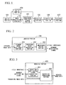
- FIG. 1 shows the constitution of the image processing device according to the present embodiment. Hereinbelow, the general functions of the constitution of the present image processing device shall be described.
- An imaging portion 101 performs image capture with a CCD or the like, and generates captured image data that is data of pixels that constitute the captured image.
- An image processing portion 102 performs spatial image processing (pre-processing) such as white balance processing and gamma processing on the captured image data, and generates processing image data that is data of the pixels that constitute the processing image.
- a processing image data storage portion 103 temporarily stores processing image data.
- a judging portion 104 judges the field importance on the basis of the characteristics of the subject using a portion of the captured image data as judgment image data for judging the field importance that shows whether or not the captured image of one field is important as an endoscope image.
- a reducing portion 105 reduces the data amount of the processing image data by performing pixel thinning of the processing image data that is read from the processing image data storage portion 103 in accordance with the field importance and obtains reduced image data.
- a compression portion 106 compresses the reduced image data to obtain compressed image data.
- a transfer portion 107 transfers the compressed image data to the outside.
- FIG. 2 shows the constitution of the judging portion 104.
- a judgment image data cutout portion 201 cuts out judgment image data from the captured image data.
- An importance index generating portion 202 generates a field importance index that is an index when judging the field importance of the captured image from the judgment image data.
- An importance judging portion 203 judges the field importance based on the field importance index.
- FIG. 3 shows the constitution of the reducing portion 105.
- a reduction rate control signal generating portion 301 generates enable in relation to the pixel thinning of the processing image data, and outputs it as a reduction rate control signal.
- a reduction processing portion 302 performs pixel thinning of the processing image data according to the reduction rate control signal, and generates reduced image data. The thinning rate of the pixel thinning is set by the reduction rate control signal.
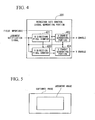
- FIG. 4 shows the constitution of the reduction rate control signal generating portion 301.
- An H direction pixel counter 401 counts the number of pixels in the H direction (horizontal direction) of the processing image.
- An H enable generating portion 402 generates an enable in relation to pixel thinning in the H direction of a processing image.
- a V direction pixel counter 403 counts the number of pixels in the V direction (perpendicular direction) of a processing image.
- a V enable generating portion 404 generates an enable in relation to pixel thinning in the V direction of a processing image.
- the present embodiment judges the field importance by this method.
- the image processing portion 102 generates the processing image data by performing predetermined image processing on the captured image data that is obtained by the imaging portion 101, and once writes the processing image data in the processing image data storage portion 103.
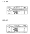
- the judgment image data cutout portion 201 of the judging portion 104 generates judgment image data that is pixel data of a judgment image in which for example the periphery of the captured image has been as shown in FIG. 5 .
- the importance index generating portion 202 after calculating the average G level of the judgment image data of one field, calculates the ratio with the average G level that is expected for an organ to be observed that is set in advance, and outputs it as a field importance index (judging original data).
- the importance judging portion 203 by comparing the field importance index and a plurality of importance judgment threshold values set in advance, outputs the field importance by judging the field importance of the captured image (for example, one of the three levels of low, medium, high) at the end of one field and generates and outputs a judgment notification signal that shows that the field importance judgment of the captured image is complete.
- the reduction rate control signal generating portion 301 in the reducing portion 105 generates a reduction rate control signal as follows in parallel with the processing image data being read out from the processing image data storage portion 103.
- pixel data of one line are read out in sequence from the pixel at the upper left of a captured image, after which the pixel data of the next line is read out in sequence from the pixel at the left end, and so on, whereby the pixel data of each line are read one by one.
- the H direction pixel counter 401 in the reduction rate control signal generating portion 301 generates an H direction pixel count value that counts the pixels in the H direction in the processing image by performing a count for each reference timing with the judgment notification signal serving as a start trigger, and performing a reset at each counting of the number of pixels in the H direction of the processing image data.
- the V direction pixel counter 403 in the same manner generates a V direction pixel count value that is a count of the pixels in the V direction in the processing image by counting at the timing at which the H direction pixel count value is reset with the judgment notification signal serving as a start trigger, and performing a reset each time the V direction pixel number of the processing image is counted.
- the H enable generating portion 402 generates an enable in relation to pixel thinning of H direction pixel data (called an H enable) from the field importance and H direction pixel count value for each pixel of the captured image.
- FIG. 6A shows the H enable generation conditions. In the case of the field importance being “low”, when the remainder of dividing the H direction pixel count value by 4 is “0", the H enable is “1", and when other than that the H enable is “0". Also, in the case of the field importance being “medium”, when the remainder of dividing the H direction pixel count value by 2 is “0", the H enable is "1", and when other than that the H enable is "0". Also, in the case of the field importance being “high”, the H enable is "1" regardless of the H direction pixel count value.
- the V enable generating portion 404 generates an enable (called a V enable) in relation to pixel thinning of V direction pixel data from the field importance and V direction pixel count value.
- FIG. 6B shows the V enable generation conditions.
- the V enable generation conditions are the same as the H enable generation conditions. By following the conditions for FIG. 6A and FIG. 6B , the enable is generated such that the lower the field importance, the higher the thinning rate.
- the reduction processing portion 302 reads the processing image data from the processing image data storage portion 103 by having the judgment notification signal serve as a start trigger and sifts through the processing image data by validating processing image data when both the H enable and V enable are "1" and otherwise invalidating the processing image data. Thereby, data reduction is performed by pixel thinning of the processing image data to obtain reduced image data.
- the compression portion 106 generates compressed image data by compressing the reduced image data using JPEG or the like.
- the transfer portion 107 transfers the compressed image data from inside the body to outside the body. Outside the body, when expanding and playing back the compressed image data, the image data of the thinned pixel positions is found by interpolation.
- the reduction rate of the processing image data is controlled according to the degree of importance of the captured image.
- the image processing device With respect to the image processing device according to the first embodiment that judges the degree of importance for each field of a captured image and performs pixel thinning at a thinning rate in accordance with the judgment result, the image processing device according to the present embodiment is one that combines the functions of performing pixel thinning at a thinning rate that differs at the center portion and peripheral portion of the captured image.
- pixel thinning of the processing image data in the present embodiment shall be described.
- a known characteristic of human visual perception is to focus more on the center portion of an image than the periphery thereof. Therefore, by utilizing this visual perception characteristic in the present embodiment, the center portion of a processing image is regarded as an important region while the periphery is regarded as a non-important region.
- Pixel thinning of the processing image data is then performed by varying the pixel thinning rate of the important region and the non-important region.
- the processing image is divided into 5 ⁇ 5 regions as shown in FIG. 8 , with each division unit being called a unit.
- the image processing device replaces the constitution of the reduction rate control signal generating portion 301 in the first embodiment shown in FIG. 3 with constitution shown in FIG. 7 , and in other respects is similar to the first embodiment. Therefore, descriptions of constitutions that are the same as the first embodiment shall be omitted, and the function of the constitution of only the reduction rate control signal generating portion 301 shall be described.
- an H direction position counter 701 counts information in relation to the position in the H direction of the processing image.
- An H enable generating portion 702 generates an enable in relation to pixel thinning in the H direction of the processing image.
- a V direction position counter 703 counts information in relation to the position in the V direction of the processing image.
- a V enable generating portion 704 generates an enable in relation to pixel thinning in the V direction of the processing image.
- the reading of processing image data from the processing image data storage portion 103 is the same as in the first embodiment, and the reduction rate control signal generating portion 301 generates a reduction rate control signal as shown below in parallel with processing image data being read from the processing image data storage portion 103.
- the H direction position counter 701 generates an H pixel count value that counts the pixels in the H direction in a unit by performing a count for each reference timing with the judgment notification signal serving as a start trigger and performing a reset at each counting of the number of pixels in the H direction of the unit. Also, the H direction position counter 701 in parallel with this generates an H unit count value that counts the units in the H direction in the processing image by performing a count at the timing at which the H pixel count value is reset with the judgment notification signal serving as a start trigger, with the H pixel count value being reset at each counting of the total number of pixels in the H direction of the processing image. Also, the H direction position counter 701 generates an increment signal that shows that the counting of the pixel number in the H direction of the processing image has been completed during resetting of the H unit count value.
- the H enable generating portion 702 generates an enable in relation to pixel thinning of H direction pixel data (called the H enable) from the field importance, the H unit count value and the H pixel count value.
- FIG. 9A shows the H enable generation conditions.
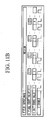
- FIG. 10A to FIG. 10C show the waveform of the H enable that is generated according to the conditions of FIG. 9A .
- FIG. 10A shows the waveform of the H enable in the case of the field importance being "low”
- FIG. 10B shows the waveform of the H enable in the case of the field importance being "medium”
- FIG. 10C shows the waveform of the H enable in the case of the field importance being "high”.
- the V direction position counter 703 generates a V pixel count value that counts the pixels in the V direction in a unit by performing a count at each increment with the judgment notification signal serving as a start trigger and performing a reset at each counting of the number of pixels in the V direction of the unit. Also, the V direction position counter 703 in parallel with this generates a V unit count value that counts the units in the V direction in the processing image by performing a count at the timing at which the V pixel count value is reset with the judgment notification signal serving as a start trigger, with the V pixel count value being reset at each counting of the total number of pixels in the V direction of the processing image.
- the V enable generating portion 704 generates an enable in relation to pixel thinning of V direction pixel data (called the V enable) from the field importance, the V unit count value and the V pixel count value.
- FIG. 9B shows the H enable generation conditions.
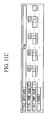
- FIG. 11A to FIG. 11C show the waveform of the V enable that is generated according to the conditions of FIG. 9B .
- FIG. 11A shows the waveform of the V enable in the case of the field importance being "low”
- FIG. 11B shows the waveform of the V enable in the case of the field importance being "medium”
- FIG. 11C shows the waveform of the V enable in the case of the field importance being "high”.
- enables are generated so that the thinning rate of the overall image increases as the field importance decreases, and in the case of the degree of importance of the image not being high, the thinning rate gradually decreases from the periphery to the center of the image. Thereafter, pixel thinning of the processing image data, generation of compressed image data, and transfer of the compressed data are performed in the same process as the first embodiment.
- the aforementioned embodiment it is possible to more efficiently reduce the power consumption and time required for transferring the image data to the outside after data reduction, similarly to the first embodiment. Also, in the case of the important region and non-important region in the captured image being known in advance (with the center portion being the important region and the periphery being the non-important region in the present embodiment), it is possible to control the reduction rate of data in accordance with the degree of importance of the captured image itself and also set a reduction rates that differ at the important region and non-important region, and so it is possible to even more efficiently reduce the power consumption and time required for transferring the image data to the outside after data reduction. Also, by gradually changing the reduction rate of the data, it is possible to smoothly alter the image quality and possible to prevent visual unnaturalness.
- the image processing device judges whether or not the capture image is important as an endoscope image for each region that divides the captured image of one field, and performs strong low pass filter (LPF) processing in accordance with the judgment result at each region.
- LPF strong low pass filter
- FIG. 12 shows the constitution of the image processing device according to the present embodiment.
- An imaging portion 1201 performs image capture with a CCD or the like, and generates captured image data that is data of pixels that constitute the captured image.
- An image processing portion 1202 performs spatial image processing such as white balance processing and gamma processing on the captured image data, and generates processing image data that is data of the pixels that constitute the processing image.
- a processing image data storage portion 1203 temporarily stores processing image data.
- a captured image data storage portion 1204 temporarily stores captured image data.
- a dividing portion 1205 divides the captured image data that is read from the captured image data storage portion 1204 and, in order to judge the degree of importance of each division region, generates a division control signal for dividing the captured image into, for example, 5 ⁇ 5 regions (areas) as shown in FIG. 13 .
- a judging portion 1206 judges the area importance that shows whether or not the captured image of the area unit is important as an endoscope image from the captured image data that is read from the captured image data storage portion 1204 and a division control signal.
- a reducing portion 1207 reduces the data amount of the processing image data by performing LPF processing of the processing image data that is read from the processing image data storage portion 1203 according to the area importance and obtains reduced image data.
- a compression portion 1208 compresses the reduced image data to obtain compressed image data.
- a transfer portion 1209 transfers the compressed image data to the outside.
- FIG. 14 shows the constitution of the dividing portion 1205.
- An H area pixel counter 1401 generates an H area pixel count value that counts the pixels in the H direction of the area.
- a V area pixel counter 1402 generates a V area pixel count value that counts the pixels in the V direction of the area.
- An H area counter 1403 generates an H area count value that counts the areas in the H direction of the captured imaged.
- a V area counter 1404 generates a V area count value that counts the areas in the V direction of the captured image.
- a count value decoder 1405 decodes the H area pixel count value, the V area pixel count value, the H area count value and the V area count value, and generates a write area coordinate signal and a read address signal described below.
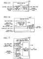
- FIG. 15 shows the constitution of the judging portion 1206.
- An importance index generating portion 1501 generates an area importance index that is an index when judging the area importance of the captured image from the judgment image data.
- An importance judging portion 1502 judges the area importance based on the area importance index.
- FIG. 16 shows the constitution of the reducing portion 1207.
- a reduction rate control signal generating portion 1601 generates an LPF coefficient when performing LPF processing on the processing image data based on the area importance, and outputs it as a reduction rate control signal.
- a reduction processing portion 1602 performs LPF processing of the processing image data in accordance with the reduction rate control signal, and generates reduced image data.
- FIG. 17 shows the constitution of the reduction rate control signal generating portion 1601.
- An importance storage portion 1701 stores the area importance corresponding to the write area coordinate signal.
- An H direction position counter 1702 generates an H direction position count value that counts the pixels in the H direction of the processing image.
- An V direction position counter 1703 generates a V direction position count value that counts the pixels in the V direction of the processing image.
- An LPF coefficient generating portion 1704 generates an LPF coefficient from the H direction position count value and the V direction position count value.
- the image processing portion 1202 generates the processing image data by performing predetermined image processing on the captured image data that is obtained by the imaging portion 1201, and once writes the processing image data in the processing image data storage portion 1203. At this time, the captured image data is also written in the captured image data storage portion 1204, and after the writing of the captured image data is completed, the captured image data storage portion 1204 generates a write complete notification signal that indicates that the writing of the captured image data has been completed:
- the dividing portion 1205 operates as shown below in parallel with the captured image data being read from the captured image data storage portion 1204.
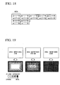
- the captured image data is read, the data of each pixel is read in sequence as shown in FIG. 18 .
- the H area pixel counter 1401 in the dividing portion 1205 generates an H area pixel count value that counts the pixels in the H direction in the area by performing a count for each reference timing with the write complete notification signal serving as a start trigger, and performing a reset at each counting of the number of pixels in the H direction of the area.
- the V area pixel counter 1402 in the same manner generates a V area pixel count value that counts the pixels in the V direction in the area by performing a count for each reference timing with the write complete notification signal serving as a start trigger, and performing a reset at each counting of the number of pixels in the V direction of the area.
- the H area counter 1403 generates an H area count value that counts the areas in the H direction in the captured image by performing a count at the timing at which the V area pixel count value is reset with the write complete notification signal serving as a start trigger, and resetting at each counting of the number of areas in the H direction.
- the V area counter 1404 in the same manner generates a V area count value that counts the areas in the V direction in the captured image by performing a count at the timing at which the H area count value is reset with the write complete notification signal serving as a start trigger, and resetting at each counting of the number of areas in the V direction.
- the count value decoder 1405 generates a read address signal for reading processing image data from the processing image data storage portion 1203 at every area similarly to FIG. 18 and a write area coordinate signal that shows the area in the captured image from the H area pixel count value, the H area count value, the V area pixel count value, and the V area count value.
- the write area coordinate signal changes at every area.
- the importance index generating portion 1501 in the judging portion 1206 generates an area importance index from the captured image data that is read from the captured image data storage portion 1204, and notifies the generated area importance index to the importance judging portion 1502 at the timing at which the write area coordinate signal changes. Also, the importance index generating portion 1501 resets the generated area importance index when notifying the area importance index to the importance judging portion 1502.
- the importance judging portion 1502 judges the area importance (for example, one of the three levels of low, medium, high) by comparing the area importance index that is notified from the importance index generating portion 1501 and a plurality of importance judgment threshold values set in advance and generates a judgment notification signal that shows that the importance judgment of all the areas is complete simultaneously with the judgment of the last area.
- the importance storage portion 1701 in the reduction rate control signal generating portion 1601 that the reducing portion 1207 is provided with stores the area importance and the write area coordinate signal in correspondence with each other. Then, the reduction rate control signal generating portion 1601 generates an LPF coefficient in the following manner in parallel with the reading of the processing image data from the processing image data storage portion 1203 in accordance with the read address signal.
- the H direction position counter 1702 generates an H pixel count value that counts the pixels in the H direction in the processing image by performing a count for each reference timing with the judgment notification signal serving as a start trigger, and performing a reset at each counting of the number of pixels in the H direction of the processing image.
- the V direction position counter 1703 in the same manner generates a V pixel count value that counts the pixels in the V direction in the processing image by performing a count at the timing at which the H pixel count value is reset with the judgment notification signal serving as a start trigger, and performing a reset at each counting of the number of pixels in the V direction of the processing image.
- the LPF coefficient generating portion 1704 generates a read area coordinate signal that shows the coordinates of the area based on the H pixel count value and the V pixel count value and reads the corresponding area importance from the importance storage portion 1701. Also, the LPF coefficient generating portion 1704 generates an in-area coordinate signal that shows the coordinates in an area based on the H pixel count value and the V pixel count value and, based on the area importance and in-area coordinate signal, generates an LPF signal that sharply changes from weak to strong from the edge to the center of the area when the area importance is "low”, generates an LPF signal that gradually changes from weak to strong from the edge to the center of the area when the area importance is "medium”, and generates an LPF signal that is uniformly weak over the entire area when the area importance is "high” (refer to FIG. 19 ).
- the reduction processing portion 1602 in the reducing portion 1207 performs data reduction by reduction of the high-frequency component of the processing image data by starting reading of the processing image data from the processing image data storage portion 1203 with the judgment notification signal serving as a trigger, and performing LPF processing of the processing image data in accordance with the LPF coefficient, and thereby obtains reduced image data.
- the compression portion 1208 generates compressed image data by compressing the reduced image data using JPEG or the like.
- the transfer portion 1209 transfers the compressed image data from inside the body to outside the body.
- LPF processing of the processing image data is executed in accordance with the degree of importance of the captured image.
- the data amount was reduced by pixel thinning and LPF processing, but the data amount may also be reduced by changing the compression rate in the compression portion 106, 1208 in accordance with the degree of importance of the image. Moreover, the data amount may be reduced by lessening the number of bits that express one pixel. For example, a pixel that was expressed with 8 bits may be expressed with 4 bits, and two pixels may be expressed with 8 bits.
- the present invention by reducing the data amount of a second image data in accordance with the degree of importance of a first image data in an image processing device that compresses image data, it is possible to achieve greater reductions in the data amount as the degree of importance decreases. As a result, it is possible to more efficiently reduce the power consumption and time required when transferring the image data after data reduction.
Landscapes
- Engineering & Computer Science (AREA)
- Multimedia (AREA)
- Signal Processing (AREA)
- Health & Medical Sciences (AREA)
- Life Sciences & Earth Sciences (AREA)
- Surgery (AREA)
- Biomedical Technology (AREA)
- Molecular Biology (AREA)
- Optics & Photonics (AREA)
- Pathology (AREA)
- Radiology & Medical Imaging (AREA)
- Biophysics (AREA)
- Physics & Mathematics (AREA)
- Heart & Thoracic Surgery (AREA)
- Medical Informatics (AREA)
- Nuclear Medicine, Radiotherapy & Molecular Imaging (AREA)
- Animal Behavior & Ethology (AREA)
- General Health & Medical Sciences (AREA)
- Public Health (AREA)
- Veterinary Medicine (AREA)
- Image Processing (AREA)
- Endoscopes (AREA)
- Measurement Of The Respiration, Hearing Ability, Form, And Blood Characteristics Of Living Organisms (AREA)
- Studio Devices (AREA)
Claims (8)
- Bildverarbeitungsvorrichtung für ein Kapselendoskop, umfassend:einen Vorverarbeitungsabschnitt (102, 1202), der eine vorbestimmte Vorverarbeitung an ersten Bilddaten durchführt und diese als zweite Bilddaten ausgibt;einen Beurteilungsabschnitt (104, 1206), der den Grad einer Relevanz der ersten Bilddaten auf Basis der Charakteristiken eines Subjekts beurteilt, das in den ersten Bilddaten enthalten ist; undeinen Reduzierungsabschnitt (105, 1207), der die Datenmenge der zweiten Bilddaten gemäß des Grades der Relevanz reduziert und diese als dritte Bilddaten ausgibt,dadurch gekennzeichnet, dass der Beurteilungsabschnitt (104, 1206) einen Beurteilungs-Original-Daten-Erzeugungs-Abschnitt (202, 1501), der Beurteilungsoriginaldaten erzeugt, und einen Relevanz-Beurteilungsabschnitt (203, 1502) aufweist, der den Grad der Relevanz durch Vergleich der Beurteilungsoriginaldaten mit einem vorab gesetzten Relevanz-Beurteilungs-Schwellwert beurteilt,wobei der Beurteilungs-Original-Daten-Erzeugungs-Abschnitt (202, 1501) ein Verhältnis von einem durchschnittlichen Grünkomponenten-Pegel der ersten Bilddaten mit einem durchschnittlichen Grünkomponenten-Pegel berechnet, der für einen vorab gesetzten Wert von Bilddaten eines zu beobachtenden Subjekts erwartet wird, und die Beurteilungs-Original-Daten erzeugt, die für die Beurteilung des Grades der Relevanz der ersten Bilddaten verwendet wird.
- Bildverarbeitungsvorrichtung nach Anspruch 1, ferner ausgestattet mit einem Teilungsabschnitt (1205), der die ersten Bilddaten in eine Mehrzahl Bereiche teilt, wobei der Beurteilungsabschnitt (104, 1206) den Grad der Relevanz eines jeden der Bereiche beurteilt und der Reduzierungsabschnitt (105, 1207) die Datenmenge von einem entsprechenden Gebiet der zweiten Bilddaten gemäß dem Grad der Relevanz eines jeden der Bereiche reduziert.
- Bildverarbeitungsvorrichtung nach Anspruch 1, ferner ausgestattet mit einem Bilddatenausschneidungsabschnitt (201), der einen bestimmten Bereich aus den ersten Bilddaten ausschneidet, wobei der Beurteilungsabschnitt (104, 1206) den Grad der Relevanz des bestimmten Bereichs beurteilt und der Reduzierungsabschnitt (105, 1207) die Datenmenge eines entsprechenden Gebiets der zweiten Bilddaten gemäß dem Grad der Relevanz des bestimmten Bereichs reduziert.
- Bildverarbeitungsvorrichtung nach Anspruch 1, bei der der Reduzierungsabschnitt (105, 1207) ausgestattet ist mit:einem Reduzierungsverarbeitungsabschnitt (302, 1602), der die Datenmenge der zweiten Bilddaten reduziert; undeinen Reduzierungsrateneinstellabschnitt (301, 1601), der eine Reduzierungsrate der Datenmenge entsprechend dem Grad der Relevanz für den Reduzierungsverarbeitungsabschnitt einstellt.
- Bildverarbeitungsvorrichtung nach Anspruch 4, bei der der Reduzierungsverarbeitungsabschnitt (302, 1602) die zweiten Bilddaten bei einem vorbestimmten Verhältnis ausdünnt und der Reduzierungsrateneinstellabschnitt (301, 1601) das vorbestimmte Verhältnis einstellt.
- Bildverarbeitungsvorrichtung gemäß Anspruch 4, bei der der Reduzierungsverarbeitungsabschnitt (302, 1602) Tiefpassfilterverarbeitung an den zweiten Bilddaten durchführt und der Reduzierungsrateneinstellabschnitt (301, 1601) einen Koeffizienten gemäß der Tiefpassfilterbearbeitung einstellt.
- Bildverarbeitungsvorrichtung gemäß einem der Ansprüche 4 bis 6, bei der der Reduzierungsrateneinstellabschnitt (301, 1601) die Reduzierungsrate von dem Äußeren eines Bildes hin zu dem Inneren graduell verändert.
- Bildverarbeitungsvorrichtung nach Anspruch 1, ferner umfassend einen Freigabeerzeugungsabschnitt (402, 404, 702, 704), der eine Freigabe in Bezug auf Pixelausdünnung von Pixeldaten für jeden Pixel eines aufgenommenen Bildes erzeugt.
Applications Claiming Priority (2)
| Application Number | Priority Date | Filing Date | Title |
|---|---|---|---|
| JP2006142416A JP2007312810A (ja) | 2006-05-23 | 2006-05-23 | 画像処理装置 |
| PCT/JP2007/060504 WO2007136087A1 (ja) | 2006-05-23 | 2007-05-23 | 画像処理装置 |
Publications (3)
| Publication Number | Publication Date |
|---|---|
| EP2020201A1 EP2020201A1 (de) | 2009-02-04 |
| EP2020201A4 EP2020201A4 (de) | 2011-11-02 |
| EP2020201B1 true EP2020201B1 (de) | 2014-10-15 |
Family
ID=38723397
Family Applications (1)
| Application Number | Title | Priority Date | Filing Date |
|---|---|---|---|
| EP07743938.8A Not-in-force EP2020201B1 (de) | 2006-05-23 | 2007-05-23 | Bildverarbeitungseinrichtung |
Country Status (5)
| Country | Link |
|---|---|
| US (1) | US8249368B2 (de) |
| EP (1) | EP2020201B1 (de) |
| JP (1) | JP2007312810A (de) |
| CN (1) | CN101448451B (de) |
| WO (1) | WO2007136087A1 (de) |
Families Citing this family (10)
| Publication number | Priority date | Publication date | Assignee | Title |
|---|---|---|---|---|
| JP5129562B2 (ja) * | 2007-12-27 | 2013-01-30 | 富士フイルム株式会社 | 光断層画像化方法およびシステム |
| JP5035987B2 (ja) * | 2008-01-28 | 2012-09-26 | 富士フイルム株式会社 | カプセル内視鏡、およびカプセル内視鏡の動作制御方法 |
| JP5031601B2 (ja) * | 2008-01-29 | 2012-09-19 | 富士フイルム株式会社 | カプセル内視鏡、およびカプセル内視鏡の動作制御方法 |
| JP5346641B2 (ja) * | 2009-03-26 | 2013-11-20 | 富士フイルム株式会社 | 超音波プローブ及び超音波診断装置 |
| JP5192591B2 (ja) * | 2012-01-16 | 2013-05-08 | 富士フイルム株式会社 | カプセル内視鏡、およびカプセル内視鏡の動作制御方法 |
| WO2014188852A1 (ja) * | 2013-05-20 | 2014-11-27 | オリンパスメディカルシステムズ株式会社 | 撮像装置 |
| JPWO2016052175A1 (ja) * | 2014-10-03 | 2017-04-27 | オリンパス株式会社 | 携帯型内視鏡システム及びプロセッサ |
| CN108135455B (zh) | 2015-10-08 | 2020-01-24 | 奥林巴斯株式会社 | 内窥镜系统 |
| CN107102714A (zh) * | 2016-02-22 | 2017-08-29 | 阿尔派株式会社 | 电子机器及电子机器的显示控制方法 |
| KR102037303B1 (ko) | 2018-10-24 | 2019-10-28 | 아주대학교 산학협력단 | 캡슐 내시경의 위치를 추정하는 방법 및 장치 |
Citations (2)
| Publication number | Priority date | Publication date | Assignee | Title |
|---|---|---|---|---|
| JPH07222145A (ja) * | 1994-01-31 | 1995-08-18 | Mitsubishi Electric Corp | 画像符号化装置 |
| US20050105807A1 (en) * | 2003-09-19 | 2005-05-19 | Tooru Suino | Delivery of moving images according to reception condition of recipient |
Family Cites Families (11)
| Publication number | Priority date | Publication date | Assignee | Title |
|---|---|---|---|---|
| JPH06334985A (ja) | 1993-05-26 | 1994-12-02 | Hitachi Ltd | 画像符号化装置 |
| US6798834B1 (en) * | 1996-08-15 | 2004-09-28 | Mitsubishi Denki Kabushiki Kaisha | Image coding apparatus with segment classification and segmentation-type motion prediction circuit |
| JPH10108197A (ja) * | 1996-09-30 | 1998-04-24 | Sony Corp | 画像符号化装置、画像符号化制御方法および画像符号化制御用プログラムを記録した媒体 |
| US6275533B1 (en) * | 1997-06-20 | 2001-08-14 | Matsushita Electric Industrial Co., Ltd. | Image processing method, image processing apparatus, and data recording medium |
| JP4493386B2 (ja) | 2003-04-25 | 2010-06-30 | オリンパス株式会社 | 画像表示装置、画像表示方法および画像表示プログラム |
| JP3810381B2 (ja) | 2003-04-25 | 2006-08-16 | オリンパス株式会社 | 画像表示装置、画像表示方法および画像表示プログラム |
| US7336833B2 (en) * | 2004-06-30 | 2008-02-26 | Given Imaging, Ltd. | Device, system, and method for reducing image data captured in-vivo |
| JP4615963B2 (ja) * | 2004-10-29 | 2011-01-19 | オリンパス株式会社 | カプセル型内視鏡装置 |
| DE102004059940A1 (de) * | 2004-12-13 | 2006-06-14 | Fraunhofer-Gesellschaft zur Förderung der angewandten Forschung e.V. | Signalkonvertierer zum Konvertieren eines Startsignals in ein Endsignal und Verfahren zum Konvertieren eines Startsignals in ein Endsignal |
| TWI300213B (en) * | 2005-05-26 | 2008-08-21 | Coretronic Corp | Image display method |
| JP4639271B2 (ja) * | 2005-12-27 | 2011-02-23 | 三星電子株式会社 | カメラ |
-
2006
- 2006-05-23 JP JP2006142416A patent/JP2007312810A/ja not_active Withdrawn
-
2007
- 2007-05-23 EP EP07743938.8A patent/EP2020201B1/de not_active Not-in-force
- 2007-05-23 CN CN200780018569.9A patent/CN101448451B/zh not_active Expired - Fee Related
- 2007-05-23 WO PCT/JP2007/060504 patent/WO2007136087A1/ja not_active Ceased
-
2008
- 2008-11-21 US US12/275,771 patent/US8249368B2/en active Active
Patent Citations (2)
| Publication number | Priority date | Publication date | Assignee | Title |
|---|---|---|---|---|
| JPH07222145A (ja) * | 1994-01-31 | 1995-08-18 | Mitsubishi Electric Corp | 画像符号化装置 |
| US20050105807A1 (en) * | 2003-09-19 | 2005-05-19 | Tooru Suino | Delivery of moving images according to reception condition of recipient |
Also Published As
| Publication number | Publication date |
|---|---|
| US8249368B2 (en) | 2012-08-21 |
| WO2007136087A1 (ja) | 2007-11-29 |
| CN101448451A (zh) | 2009-06-03 |
| CN101448451B (zh) | 2012-06-20 |
| JP2007312810A (ja) | 2007-12-06 |
| EP2020201A4 (de) | 2011-11-02 |
| US20090141989A1 (en) | 2009-06-04 |
| EP2020201A1 (de) | 2009-02-04 |
Similar Documents
| Publication | Publication Date | Title |
|---|---|---|
| US8249368B2 (en) | Image processing device | |
| CN108391035B (zh) | 一种拍摄方法、装置与设备 | |
| US9066017B2 (en) | Viewfinder display based on metering images | |
| EP1988705A1 (de) | Verbesserungen für oder in Bezug auf Bildsensoren | |
| KR101295441B1 (ko) | 기록 매체, 동화상 처리 장치 및 방법, 촬상 장치, 호스트 단말기 및 촬상 시스템 | |
| CN108989699B (zh) | 图像合成方法、装置、成像设备、电子设备以及计算机可读存储介质 | |
| JP2009118483A (ja) | オブジェクト追跡を用いたデジタル画像の手ぶれ補正装置および方法 | |
| JP7039183B2 (ja) | 画像処理装置、画像処理方法、及びプログラム | |
| US20220232173A1 (en) | Method and device of image processing, imaging system and storage medium | |
| CN101888478B (zh) | 摄像装置、数据生成装置及数据构造 | |
| JP2007124088A (ja) | 画像撮影装置 | |
| US20110157426A1 (en) | Video processing apparatus and video processing method thereof | |
| JP2007228337A (ja) | 画像撮影装置 | |
| US20100253806A1 (en) | Imaging system and imaging method thereof | |
| JP2007188126A (ja) | 画像明るさ算出装置および方法並びにプログラム | |
| US10567644B2 (en) | Image capturing device, image processing method and image processing device for stitching and blending operations | |
| JP2001292449A (ja) | 画像処理装置、画像処理方法、及び記録媒体 | |
| CN112153317A (zh) | 一种图像质量控制方法及其系统和设备 | |
| CN112422782A (zh) | 显示控制设备及其控制方法和计算机可读存储介质 | |
| JP2015132949A (ja) | 画像処理装置、画像処理方法及びプログラム | |
| US11310442B2 (en) | Display control apparatus for displaying image with/without a frame and control method thereof | |
| TWI424371B (zh) | Video processing device and processing method thereof | |
| CN100591113C (zh) | 图像处理装置 | |
| CN120711282A (zh) | 系统、摄像机、设备以及方法 | |
| JP2025058676A (ja) | 教師データ、学習済みモデル、撮像装置、学習装置、教師データの作成方法、及び学習済みモデルの生成方法 |
Legal Events
| Date | Code | Title | Description |
|---|---|---|---|
| PUAI | Public reference made under article 153(3) epc to a published international application that has entered the european phase |
Free format text: ORIGINAL CODE: 0009012 |
|
| 17P | Request for examination filed |
Effective date: 20081127 |
|
| AK | Designated contracting states |
Kind code of ref document: A1 Designated state(s): AT BE BG CH CY CZ DE DK EE ES FI FR GB GR HU IE IS IT LI LT LU LV MC MT NL PL PT RO SE SI SK TR |
|
| AX | Request for extension of the european patent |
Extension state: AL BA HR MK RS |
|
| DAX | Request for extension of the european patent (deleted) | ||
| RBV | Designated contracting states (corrected) |
Designated state(s): DE FR GB |
|
| A4 | Supplementary search report drawn up and despatched |
Effective date: 20110930 |
|
| RIC1 | Information provided on ipc code assigned before grant |
Ipc: A61B 5/07 20060101ALI20110926BHEP Ipc: A61B 1/04 20060101ALI20110926BHEP Ipc: G06T 3/40 20060101ALI20110926BHEP Ipc: G06T 5/10 20060101ALI20110926BHEP Ipc: A61B 1/00 20060101AFI20110926BHEP |
|
| 17Q | First examination report despatched |
Effective date: 20130911 |
|
| GRAP | Despatch of communication of intention to grant a patent |
Free format text: ORIGINAL CODE: EPIDOSNIGR1 |
|
| RIC1 | Information provided on ipc code assigned before grant |
Ipc: A61B 1/04 20060101ALI20140502BHEP Ipc: A61B 1/00 20060101AFI20140502BHEP Ipc: G06T 5/10 20060101ALI20140502BHEP Ipc: G06T 3/40 20060101ALI20140502BHEP |
|
| INTG | Intention to grant announced |
Effective date: 20140520 |
|
| GRAS | Grant fee paid |
Free format text: ORIGINAL CODE: EPIDOSNIGR3 |
|
| GRAA | (expected) grant |
Free format text: ORIGINAL CODE: 0009210 |
|
| AK | Designated contracting states |
Kind code of ref document: B1 Designated state(s): DE FR GB |
|
| REG | Reference to a national code |
Ref country code: GB Ref legal event code: FG4D |
|
| REG | Reference to a national code |
Ref country code: DE Ref legal event code: R096 Ref document number: 602007038910 Country of ref document: DE Effective date: 20141127 |
|
| REG | Reference to a national code |
Ref country code: DE Ref legal event code: R097 Ref document number: 602007038910 Country of ref document: DE |
|
| PLBE | No opposition filed within time limit |
Free format text: ORIGINAL CODE: 0009261 |
|
| STAA | Information on the status of an ep patent application or granted ep patent |
Free format text: STATUS: NO OPPOSITION FILED WITHIN TIME LIMIT |
|
| 26N | No opposition filed |
Effective date: 20150716 |
|
| GBPC | Gb: european patent ceased through non-payment of renewal fee |
Effective date: 20150523 |
|
| REG | Reference to a national code |
Ref country code: FR Ref legal event code: ST Effective date: 20160129 |
|
| PG25 | Lapsed in a contracting state [announced via postgrant information from national office to epo] |
Ref country code: GB Free format text: LAPSE BECAUSE OF NON-PAYMENT OF DUE FEES Effective date: 20150523 |
|
| PG25 | Lapsed in a contracting state [announced via postgrant information from national office to epo] |
Ref country code: FR Free format text: LAPSE BECAUSE OF NON-PAYMENT OF DUE FEES Effective date: 20150601 |
|
| PGFP | Annual fee paid to national office [announced via postgrant information from national office to epo] |
Ref country code: DE Payment date: 20170516 Year of fee payment: 11 |
|
| REG | Reference to a national code |
Ref country code: DE Ref legal event code: R119 Ref document number: 602007038910 Country of ref document: DE |
|
| PG25 | Lapsed in a contracting state [announced via postgrant information from national office to epo] |
Ref country code: DE Free format text: LAPSE BECAUSE OF NON-PAYMENT OF DUE FEES Effective date: 20181201 |