EP2020171A1 - Système et procédé de contrôle d'un véhicule en réponse à une limite particulière - Google Patents
Système et procédé de contrôle d'un véhicule en réponse à une limite particulière Download PDFInfo
- Publication number
- EP2020171A1 EP2020171A1 EP08158222A EP08158222A EP2020171A1 EP 2020171 A1 EP2020171 A1 EP 2020171A1 EP 08158222 A EP08158222 A EP 08158222A EP 08158222 A EP08158222 A EP 08158222A EP 2020171 A1 EP2020171 A1 EP 2020171A1
- Authority
- EP
- European Patent Office
- Prior art keywords
- vehicle
- boundary
- work area
- area
- turn
- Prior art date
- Legal status (The legal status is an assumption and is not a legal conclusion. Google has not performed a legal analysis and makes no representation as to the accuracy of the status listed.)
- Granted
Links
- 238000000034 method Methods 0.000 title claims abstract description 20
- 230000004044 response Effects 0.000 title abstract description 3
- 238000007689 inspection Methods 0.000 claims abstract description 6
- 241001092459 Rubus Species 0.000 claims description 3
- 235000017848 Rubus fruticosus Nutrition 0.000 claims description 3
- 239000011435 rock Substances 0.000 claims description 3
- XLYOFNOQVPJJNP-UHFFFAOYSA-N water Substances O XLYOFNOQVPJJNP-UHFFFAOYSA-N 0.000 claims description 3
- 238000012545 processing Methods 0.000 description 7
- 230000008569 process Effects 0.000 description 6
- 239000000463 material Substances 0.000 description 4
- 238000010586 diagram Methods 0.000 description 3
- 238000003306 harvesting Methods 0.000 description 3
- 239000010902 straw Substances 0.000 description 3
- 238000013459 approach Methods 0.000 description 2
- 238000004140 cleaning Methods 0.000 description 2
- 238000013500 data storage Methods 0.000 description 2
- 238000012546 transfer Methods 0.000 description 2
- 230000008859 change Effects 0.000 description 1
- 238000004590 computer program Methods 0.000 description 1
- 238000010276 construction Methods 0.000 description 1
- 230000001419 dependent effect Effects 0.000 description 1
- 230000000694 effects Effects 0.000 description 1
- 238000003973 irrigation Methods 0.000 description 1
- 230000002262 irrigation Effects 0.000 description 1
- 230000007246 mechanism Effects 0.000 description 1
- 238000010899 nucleation Methods 0.000 description 1
- 230000008520 organization Effects 0.000 description 1
- 230000000007 visual effect Effects 0.000 description 1
Images


Classifications
-
- A—HUMAN NECESSITIES
- A01—AGRICULTURE; FORESTRY; ANIMAL HUSBANDRY; HUNTING; TRAPPING; FISHING
- A01B—SOIL WORKING IN AGRICULTURE OR FORESTRY; PARTS, DETAILS, OR ACCESSORIES OF AGRICULTURAL MACHINES OR IMPLEMENTS, IN GENERAL
- A01B79/00—Methods for working soil
- A01B79/005—Precision agriculture
Definitions
- the present invention relates generally to the field of agricultural equipment. More particularly, the present invention relates to the use of agricultural equipment in planting, harvesting and other operations.
- Conventional agricultural combines include a header leading the combine, having a forward gathering portion and a feederhouse portion which contains elements for processing crop material and/or transferring the crop material from the gathering portion to the body of the combine.
- the grain is separated from the chaff and straw, collected, and thereafter unloaded via an auger.
- Such combines have a variety of designs.
- a display interface is configured to define a boundary around a non-traversable area within a work area based upon a prior inspection.
- a location-determining receiver determines a position of the vehicle.
- a warning alarm is generated for an operator if the determined position of the vehicle traverses the boundary.
- FIG. 1 shows an example agricultural combine 10 of the type incorporating an axial rotary crop-processing unit.
- the combine 10 comprises a supporting structure or chassis 12 mounting a ground engaging mechanism 14 shown in the form of tires. Alternatively, tracks can be used in place of tires.
- a harvesting platform 16 is used for harvesting a crop and directing the crop to a feederhouse 18. The harvested crop is directed by the feederhouse 18 to a beater 20. The beater directs the crop upwardly to a rotary crop-processing unit 24.
- the rotary crop-processing unit is located between the side sheets of the combine. The side sheets form part of the supporting structure 12.
- the rotary crop-processing unit 24 comprises a rotor housing 26 and a rotor 28 located within the housing.
- the harvested crop enters the housing through an inlet 22 at the inlet end 30 of the housing 26.
- the rotor is provided with an inlet feed portion 32, a threshing portion 33, and a separating portion 34.
- the rotor housing has a corresponding infeed section 36, a threshing section 38, and a separating section 40.
- Both the threshing portion 33 and the separating portion 34 of the rotor are provided with crop engaging members (not shown).
- the threshing section 38 of the housing is provided with a concave 46 while the separating section 40 of the housing is provided with a grate 48. Grain and chaff released from the crop mat fall through the concave 46 and grate 48.
- the concave and the grate prevent the passage of crop material larger than grain or chaff from entering the combine cleaning system 50 below the rotary crop-processing unit 24.
- Grain and chaff falling through the concave and grate is directed to the cleaning system 50 that removes the chaff from the grain.
- the clean grain is then directed by an elevator (not shown) to clean the grain tank 52 where it can be directed to a truck or grain cart by unloading the auger 54.
- Straw that reaches the end 61 of the housing is expelled through an outlet 56 to a beater 58.
- the beater propels the straw out the rear of the combine.
- the end 61 is thus the outlet end of the housing.
- the crop material moves through the rotary crop-processing unit in a crop flow direction from the inlet end 30 to the outlet end 61 of the housing.
- the operation of the combine is controlled from the operator cab 60.
- the header 16 can be lifted by use of lift cylinders 63.
- the auger 54 can be pivoted via a cylinder or motor (not shown) about a vertical axis between an inboard orientation shown and an outboard orientation, substantially perpendicular to the traveling direction of the combine, to offload grain to a body of a truck.
- the auger can be pivoted inboard, substantially parallel to the direction of travel of the combine when not in use.
- the various embodiments of the present invention may be used with a tractor that pulls an implement via a hitch, with the implement being typically powered by a tractor's power take-off shaft (PTO) that is coupled to the implement.
- PTO power take-off shaft
- various embodiments may operate in conjunction with a tractor that can raise or lower a hitch, retract a hitch, and change the speed, direction, or the on/off status of the PTO.
- the implement may comprise, for example, a planter, a cultivator, a pull-behind mower, a planter or seeding apparatus, a scraper (for leveling land or making roads, or irrigation or drainage channels), a digger or trencher (e.g., for laying drain tile), or other agricultural or construction equipment.
- a planter for example, a planter, a cultivator, a pull-behind mower, a planter or seeding apparatus, a scraper (for leveling land or making roads, or irrigation or drainage channels), a digger or trencher (e.g., for laying drain tile), or other agricultural or construction equipment.
- Various embodiments of the present invention provide a system and method by which end-turns and the execution of sequences can be automated in real-time based on approaching boundaries. In other words, no pre-planning is necessary once boundaries and a turn pattern have been defined, with both being definable in the vehicle and in the field). Once these items are defined, the system create end-turns based on what type of boundary is approaching and the turn path that has been prescribed. The system simultaneously determines which vehicle functions to execute based on pre-recorded sequences that can be defined from the cab and executes the turn and the sequence automatically based on the location (which can be determined, for example, via GPS) and speed of the vehicle and its relationship to boundaries.
- This system is capable of reacting to approaching boundaries "on the fly," and the operator can make necessary changes from the cab if necessary in order to avoid any obstacles. Additionally, as a single GPS and display system may be used to perform the necessary activities associated with the various embodiments of the present invention, can clutter can also be reduced.
- the system uses a set of four sequences that are executed separately based on the type of boundary being crossed. These sequences are (1) Enter Headlands (the area at the end of a planted field where machinery is turned); (2) Exit Headlands; (3) Enter Passable Interior Boundaries; and (4) Exit Passable Interior Boundaries. Each of these sequences can be unique and drive the system to perform different actions. For example, entering a passable interior such as a waterway, the "Enter Passable Interior Boundary" sequence can have the machine slow down and only partially raise the implement. In contrast, when entering a headland, the "Enter Headlands" sequence can have the machine turn the differential lock to OFF, slow down, and then raise the implement completely out of the ground before completing a turn.
- a special situation can exist when the vehicle approaches an impassable boundary.
- an external boundary of a field or some form of internal boundary such as a pond
- the can system realizes that an impassable area is ahead, and in turn notify the operator to be alert and take control if necessary.
- Audible and/or visual tones may be used to ensure that the alert is acknowledged.
- FIG. 2 is a flow chart showing how various embodiments of the present invention may be implemented.
- a work area is inspected prior to operating a vehicle in the work area. This inspection serves to identify non-traversable areas which cannot be safely or expediently traversed by the vehicle.
- a boundary is established around the non-traversable area within the work area based on the inspection. This boundary may be established via a user interface of the vehicle.
- a position of the vehicle is determined via a location-determining receiver such as a GPS system.
- a warning alarm is generated for an operator if the determined position of the vehicle traverses the boundary.
- the non-traversable area may contain an obstacle and may comprise, but is not limited to, a hedge, vegetation, tree growth, bushes, bramble, a wooded area, a tree, a bush, a mud slide, a rock slide, a stream, a brook, a pond, a lake, a river, flood water, and a swamp.
- the vehicle can also be prevented from executing the turn if the vehicle, and this is represented at 250.
- a turn may be associated, for example, with a headland region between an outer border of the work area and an interior border of the work area.
- the boundary may also lie within an interior of the work area or a headland of the work area.
- the system may utilize "Minimize Skip” versus “Minimize Overlap” settings. These settings may be determined by the operator and can be used to make sure one or more implements are raised ahead of an approaching boundary or only after completely traversing through the boundary.
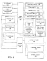
- Figures 3 and 4 are schematic diagrams of systems by which a sequence of vehicle events can be controlled according to different embodiments of the present invention.
- a data storage device 140 such as a computer memory can save information such as vehicle events 142 and established sequences 144.
- the data storage unit 140 is communicatively connected to a data processor 126.
- the data processor 126 can implement various programs, routines, sub-routines etc.
- the data processor can implement a boundary definer 128, an event definer 130, a sequence manager 132 (which may include a sequence definer, sequence editor, etc.), and an execution manager 134, with the execution manager performing functions such as adjusting speeds and compensating for changes in function.
- the data processor 126 is communicatively connected to a first databus 122.
- Other items which may be connected in some form to the first databus 122 include a timer 136 and a location-determining receiver 138.
- the location-determining receiver may comprise, for example, a Global Positioning System (GPS) receiver.
- GPS Global Positioning System
- a motion sensor 152 may also be communicatively connected to the first databus 122.
- the motion sensor 152 may comprise, for example, a velocity sensor and/or an accelerometer.
- a first sensor 110, a second sensor 112 and a third sensor 114 may also be operatively connected to the first databus 122, with these sensors comprising, for example, implement height sensors, hitch position sensors, power take-off shaft sensors, RPM sensors, etc.
- the first databus 122 can transfer data from any of these components to one of a plurality of actuators.
- a first actuator 116, a second actuator 118 and a third actuator are shown. These actuators may comprise, for example, implement actuators, hitch actuators, power take-off actuators, etc.
- Each of the first, second and third actuators 116, 118 and 120 may in turn be communicatively connected to a second databus 124, which transfer data to a vehicle controller 146 and ultimately the vehicle's propulsion system 148, braking system 150, and other systems of the vehicle that are known in the art.
Landscapes
- Life Sciences & Earth Sciences (AREA)
- Engineering & Computer Science (AREA)
- Mechanical Engineering (AREA)
- Soil Sciences (AREA)
- Environmental Sciences (AREA)
- Control Of Position, Course, Altitude, Or Attitude Of Moving Bodies (AREA)
- Position Fixing By Use Of Radio Waves (AREA)
- Guiding Agricultural Machines (AREA)
- Controls For Constant Speed Travelling (AREA)
Applications Claiming Priority (1)
| Application Number | Priority Date | Filing Date | Title |
|---|---|---|---|
| US11/831,831 US8635011B2 (en) | 2007-07-31 | 2007-07-31 | System and method for controlling a vehicle in response to a particular boundary |
Publications (2)
| Publication Number | Publication Date |
|---|---|
| EP2020171A1 true EP2020171A1 (fr) | 2009-02-04 |
| EP2020171B1 EP2020171B1 (fr) | 2018-09-12 |
Family
ID=39962729
Family Applications (1)
| Application Number | Title | Priority Date | Filing Date |
|---|---|---|---|
| EP08158222.3A Active EP2020171B1 (fr) | 2007-07-31 | 2008-06-13 | Système et procédé de contrôle d'un véhicule en réponse à une limite particulière |
Country Status (4)
| Country | Link |
|---|---|
| US (1) | US8635011B2 (fr) |
| EP (1) | EP2020171B1 (fr) |
| AU (1) | AU2008202037B2 (fr) |
| BR (1) | BRPI0803510B1 (fr) |
Cited By (3)
| Publication number | Priority date | Publication date | Assignee | Title |
|---|---|---|---|---|
| WO2012122448A1 (fr) * | 2011-03-10 | 2012-09-13 | Agco Corporation | Périmètre de gardiennage virtuel mobile pour la localisation de machines agricoles |
| EP3224734A4 (fr) * | 2014-11-24 | 2018-04-11 | Precision Planting LLC | Système et procédés pour identifier des champs et des tâches |
| CN111683517A (zh) * | 2018-02-13 | 2020-09-18 | 罗伯特·博世有限公司 | 自主农业系统和用于运行农业系统的方法 |
Families Citing this family (12)
| Publication number | Priority date | Publication date | Assignee | Title |
|---|---|---|---|---|
| WO2014105927A1 (fr) * | 2012-12-28 | 2014-07-03 | Agco Corporation | Utilisation d'une rampe virtuelle pour diriger un équipement agricole le long du bord de zones travaillées/non travaillées |
| US10180328B2 (en) * | 2013-07-10 | 2019-01-15 | Agco Coporation | Automating distribution of work in a field |
| US10251329B2 (en) | 2016-06-10 | 2019-04-09 | Cnh Industrial Canada, Ltd. | Planning and control of autonomous agricultural operations |
| US10143126B2 (en) | 2016-06-10 | 2018-12-04 | Cnh Industrial America Llc | Planning and control of autonomous agricultural operations |
| US20180341264A1 (en) * | 2017-05-24 | 2018-11-29 | Ford Global Technologies, Llc | Autonomous-vehicle control system |
| US11590522B2 (en) | 2018-02-13 | 2023-02-28 | SmartApply, Inc. | Spraying systems, kits, vehicles, and methods of use |
| US10869423B2 (en) | 2018-02-13 | 2020-12-22 | Steven R. Booher | Kits, systems, and methods for sprayers |
| US10806079B2 (en) | 2018-02-26 | 2020-10-20 | Deere & Company | Automatic product harvesting method and control system |
| US20200060061A1 (en) * | 2018-08-22 | 2020-02-27 | Cnh Industrial America Llc | Systems and methods for controlling the position of row units of an agricultural implement |
| US11178804B2 (en) | 2019-06-04 | 2021-11-23 | Cnh Industrial America Llc | Ground engaging tool positioning system |
| US12016257B2 (en) | 2020-02-19 | 2024-06-25 | Sabanto, Inc. | Methods for detecting and clearing debris from planter gauge wheels, closing wheels and seed tubes |
| US20230413711A1 (en) * | 2022-06-23 | 2023-12-28 | Deere & Company | Modifying Vehicle Behavior based on Boundary Type |
Citations (3)
| Publication number | Priority date | Publication date | Assignee | Title |
|---|---|---|---|---|
| WO1998046065A1 (fr) * | 1997-04-16 | 1998-10-22 | Carnegie Mellon University | Machine agricole de recolte commandee par robot |
| DE19921105A1 (de) | 1998-05-11 | 2000-01-05 | Caterpillar Inc | Verfahren und Vorrichtung zur Bestimmung der Lage von Sämlingen während des Ackerbaus |
| FR2800232A1 (fr) * | 1999-10-27 | 2001-05-04 | Renault Agriculture | Procede pour le guidage automatique d'un engin et dispositif correspondant |
Family Cites Families (45)
| Publication number | Priority date | Publication date | Assignee | Title |
|---|---|---|---|---|
| US3468379A (en) | 1966-03-03 | 1969-09-23 | John C Allen Jr | Automatic farming apparatus |
| US3606933A (en) | 1967-04-05 | 1971-09-21 | John Clarence Allen Jr | Automatic farming apparatus |
| NL7800648A (nl) | 1978-01-19 | 1979-07-23 | Lely Nv C Van Der | Trekker. |
| JPS58144214A (ja) | 1982-02-19 | 1983-08-27 | Kubota Ltd | テイ−チング・プレイバツク方式の自動走行車輌 |
| US4518044A (en) | 1982-03-22 | 1985-05-21 | Deere & Company | Vehicle with control system for raising and lowering implement |
| JP3673285B2 (ja) | 1992-10-09 | 2005-07-20 | 櫻護謨株式会社 | 屋外作業自動化システム |
| US5543802A (en) | 1993-03-01 | 1996-08-06 | Motorola, Inc. | Position/navigation device and method |
| DE4428824C2 (de) | 1994-08-16 | 1998-05-07 | Deere & Co | Steuereinrichtung zur Ansteuerung von Steuergeräten eines Arbeitsfahrzeuges |
| US5704546A (en) * | 1995-09-15 | 1998-01-06 | Captstan, Inc. | Position-responsive control system and method for sprayer |
| DE19629618A1 (de) | 1996-07-23 | 1998-01-29 | Claas Ohg | Routenplanungssystem für landwirtschaftliche Arbeitsfahrzeuge |
| DE19630419A1 (de) | 1996-07-27 | 1998-01-29 | Claas Ohg | Vorrichtung zur Ansteuerung mindestes eines Stellorgans eines Arbeitsfahrzeuges |
| US5978723A (en) * | 1996-11-22 | 1999-11-02 | Case Corporation | Automatic identification of field boundaries in a site-specific farming system |
| US5961573A (en) * | 1996-11-22 | 1999-10-05 | Case Corporation | Height control of an agricultural tool in a site-specific farming system |
| US5987383C1 (en) * | 1997-04-28 | 2006-06-13 | Trimble Navigation Ltd | Form line following guidance system |
| US5899950A (en) | 1997-07-07 | 1999-05-04 | Case Corporation | Sequential command repeater system for off-road vehicles |
| DE19830858A1 (de) | 1998-07-10 | 2000-01-13 | Claas Selbstfahr Erntemasch | Vorrichtung und Verfahren zur Bestimmung einer virtuellen Position |
| US6199000B1 (en) * | 1998-07-15 | 2001-03-06 | Trimble Navigation Limited | Methods and apparatus for precision agriculture operations utilizing real time kinematic global positioning system systems |
| US6141614A (en) * | 1998-07-16 | 2000-10-31 | Caterpillar Inc. | Computer-aided farming system and method |
| US6119069A (en) * | 1999-03-01 | 2000-09-12 | Case Corporation | System and method for deriving field boundaries using alpha shapes |
| US6236924B1 (en) * | 1999-06-21 | 2001-05-22 | Caterpillar Inc. | System and method for planning the operations of an agricultural machine in a field |
| US6266595B1 (en) * | 1999-08-12 | 2001-07-24 | Martin W. Greatline | Method and apparatus for prescription application of products to an agricultural field |
| US6611755B1 (en) | 1999-12-19 | 2003-08-26 | Trimble Navigation Ltd. | Vehicle tracking, communication and fleet management system |
| AU2001268181A1 (en) * | 2000-06-05 | 2001-12-17 | Ag-Chem Equipment Company, Inc. | System and method for creating demo application maps for site-specific farming |
| US6681551B1 (en) | 2002-07-11 | 2004-01-27 | Deere & Co. | Programmable function control for combine |
| DE10250694B3 (de) | 2002-10-31 | 2004-02-12 | CNH Österreich GmbH | Verfahren zur Steuerung eines landwirtschaftlichen Nutzfahrzeuges |
| US7162348B2 (en) | 2002-12-11 | 2007-01-09 | Hemisphere Gps Llc | Articulated equipment position control system and method |
| SE526913C2 (sv) * | 2003-01-02 | 2005-11-15 | Arnex Navigation Systems Ab | Förfarande i form av intelligenta funktioner för fordon och automatiska lastmaskiner gällande kartläggning av terräng och materialvolymer, hinderdetektering och styrning av fordon och arbetsredskap |
| GB0306898D0 (en) * | 2003-03-26 | 2003-04-30 | Bouchard Michel | Vehicle proximity alarm system |
| US6907336B2 (en) * | 2003-03-31 | 2005-06-14 | Deere & Company | Method and system for efficiently traversing an area with a work vehicle |
| US7010425B2 (en) * | 2003-03-31 | 2006-03-07 | Deere & Company | Path planner and a method for planning a path of a work vehicle |
| US6934615B2 (en) * | 2003-03-31 | 2005-08-23 | Deere & Company | Method and system for determining an efficient vehicle path |
| US7228214B2 (en) | 2003-03-31 | 2007-06-05 | Deere & Company | Path planner and method for planning a path plan having a spiral component |
| US7216033B2 (en) | 2003-03-31 | 2007-05-08 | Deere & Company | Path planner and method for planning a contour path of a vehicle |
| US7110881B2 (en) | 2003-10-07 | 2006-09-19 | Deere & Company | Modular path planner |
| US7079943B2 (en) | 2003-10-07 | 2006-07-18 | Deere & Company | Point-to-point path planning |
| DE102004027242A1 (de) * | 2004-06-03 | 2005-12-22 | Claas Selbstfahrende Erntemaschinen Gmbh | Routenplanungssystem für landwirtschaftliche Arbeitsmaschinen |
| US7225060B2 (en) * | 2004-07-30 | 2007-05-29 | Novariant, Inc. | Vehicle control system with user-guided calibration |
| US20060064222A1 (en) * | 2004-09-21 | 2006-03-23 | Accurtrak Systems Limited | Kit for providing an automatic steering system |
| US7451030B2 (en) * | 2005-02-04 | 2008-11-11 | Novariant, Inc. | System and method for interactive selection and determination of agricultural vehicle guide paths offset from each other with varying curvature along their length |
| DE102005008105A1 (de) * | 2005-02-21 | 2006-08-31 | Amazonen-Werke H. Dreyer Gmbh & Co. Kg | Elektronisches Maschinen-Management-System |
| US7490678B2 (en) * | 2005-04-21 | 2009-02-17 | A.I.L., Inc. | GPS controlled guidance system for farm tractor/implement combination |
| US7743591B2 (en) * | 2006-02-10 | 2010-06-29 | Syngenta Participations, Ag | Research plot harvester for continuous plot to plot grain evaluation |
| DE102006019216A1 (de) * | 2006-04-21 | 2007-10-25 | Claas Selbstfahrende Erntemaschinen Gmbh | Verfahren zur Steuerung eines landwirtschaftlichen Maschinensystems |
| US7739015B2 (en) * | 2007-07-31 | 2010-06-15 | Deere & Company | System and method for controlling a vehicle with a sequence of vehicle events |
| US8209075B2 (en) * | 2007-07-31 | 2012-06-26 | Deere & Company | Method and system for generating end turns |
-
2007
- 2007-07-31 US US11/831,831 patent/US8635011B2/en active Active
-
2008
- 2008-05-07 AU AU2008202037A patent/AU2008202037B2/en active Active
- 2008-06-13 EP EP08158222.3A patent/EP2020171B1/fr active Active
- 2008-06-30 BR BRPI0803510-5A patent/BRPI0803510B1/pt active IP Right Grant
Patent Citations (3)
| Publication number | Priority date | Publication date | Assignee | Title |
|---|---|---|---|---|
| WO1998046065A1 (fr) * | 1997-04-16 | 1998-10-22 | Carnegie Mellon University | Machine agricole de recolte commandee par robot |
| DE19921105A1 (de) | 1998-05-11 | 2000-01-05 | Caterpillar Inc | Verfahren und Vorrichtung zur Bestimmung der Lage von Sämlingen während des Ackerbaus |
| FR2800232A1 (fr) * | 1999-10-27 | 2001-05-04 | Renault Agriculture | Procede pour le guidage automatique d'un engin et dispositif correspondant |
Cited By (4)
| Publication number | Priority date | Publication date | Assignee | Title |
|---|---|---|---|---|
| WO2012122448A1 (fr) * | 2011-03-10 | 2012-09-13 | Agco Corporation | Périmètre de gardiennage virtuel mobile pour la localisation de machines agricoles |
| EP3224734A4 (fr) * | 2014-11-24 | 2018-04-11 | Precision Planting LLC | Système et procédés pour identifier des champs et des tâches |
| US10817812B2 (en) | 2014-11-24 | 2020-10-27 | The Climate Corporation | System and methods for identifying fields and tasks |
| CN111683517A (zh) * | 2018-02-13 | 2020-09-18 | 罗伯特·博世有限公司 | 自主农业系统和用于运行农业系统的方法 |
Also Published As
| Publication number | Publication date |
|---|---|
| US20090037096A1 (en) | 2009-02-05 |
| US8635011B2 (en) | 2014-01-21 |
| AU2008202037A1 (en) | 2009-02-19 |
| EP2020171B1 (fr) | 2018-09-12 |
| AU2008202037B2 (en) | 2011-11-24 |
| BRPI0803510B1 (pt) | 2019-05-14 |
| BRPI0803510A2 (pt) | 2009-08-25 |
Similar Documents
| Publication | Publication Date | Title |
|---|---|---|
| EP2020171B1 (fr) | Système et procédé de contrôle d'un véhicule en réponse à une limite particulière | |
| EP3453239B1 (fr) | Système pour optimiser les réglages de machines agricoles | |
| EP3841859B1 (fr) | Moissonneuse, système de détection de conditions environnantes, programme de détection de conditions environnantes, support d'enregistrement enregistrant le programme de détection de conditions environnantes et procédé de détection de conditions environnantes | |
| EP2020170B1 (fr) | Système et procédé de contrôle d'un véhicule avec une séquence d'événements de véhicule | |
| EP1269823B1 (fr) | Système de réglage d'une tête de récolte d'une machine de récolte | |
| CN112189227A (zh) | 地图信息生成系统以及作业援助系统 | |
| DE102014208068A1 (de) | Erntemaschine mit sensorbasierter Einstellung eines Arbeitsparameters | |
| US11350568B2 (en) | Location based chop to swath conversion for riparian buffer zone management | |
| WO2014093814A1 (fr) | Estimation de charge prédictive par vision frontale | |
| JP2016010372A (ja) | 無人操縦コンバインの自動制御装置 | |
| WO2020218464A1 (fr) | Moissonneuse, programme de détermination d'obstacle, support d'enregistrement sur lequel le programme de détermination d'obstacle est enregistré, procédé de détermination d'obstacle, machine de travail agricole, programme de commande, support d'enregistrement sur lequel est enregistré le programme de commande, et procédé de commande | |
| WO2022123448A1 (fr) | Système robotique agricole et procédé de fonctionnement | |
| US20220287216A1 (en) | Working vehicle | |
| Jotautiené et al. | Automatic steering of combine harvester for agricultural and environmental monitoring. | |
| Juostas et al. | Evaluation of combine harvester parameters using manual and auto-steering modes | |
| JP7546470B2 (ja) | 農作業機 | |
| JP2003180152A (ja) | 精密農法 | |
| JP7423443B2 (ja) | 収穫機 | |
| WO2022239779A1 (fr) | Moissonneuse-batteuse et procédé associé | |
| JP2024085050A (ja) | システム及び作業車 | |
| JP2024076610A (ja) | 作業車 | |
| JP2023005113A (ja) | 作業支援システム | |
| JP2020025517A (ja) | 作業車両 | |
| JP2019092452A (ja) | 農作業車 |
Legal Events
| Date | Code | Title | Description |
|---|---|---|---|
| PUAI | Public reference made under article 153(3) epc to a published international application that has entered the european phase |
Free format text: ORIGINAL CODE: 0009012 |
|
| AK | Designated contracting states |
Kind code of ref document: A1 Designated state(s): AT BE BG CH CY CZ DE DK EE ES FI FR GB GR HR HU IE IS IT LI LT LU LV MC MT NL NO PL PT RO SE SI SK TR |
|
| AX | Request for extension of the european patent |
Extension state: AL BA MK RS |
|
| 17P | Request for examination filed |
Effective date: 20090804 |
|
| 17Q | First examination report despatched |
Effective date: 20090827 |
|
| AKX | Designation fees paid |
Designated state(s): DE GB |
|
| GRAP | Despatch of communication of intention to grant a patent |
Free format text: ORIGINAL CODE: EPIDOSNIGR1 |
|
| INTG | Intention to grant announced |
Effective date: 20180413 |
|
| GRAS | Grant fee paid |
Free format text: ORIGINAL CODE: EPIDOSNIGR3 |
|
| GRAA | (expected) grant |
Free format text: ORIGINAL CODE: 0009210 |
|
| AK | Designated contracting states |
Kind code of ref document: B1 Designated state(s): DE GB |
|
| REG | Reference to a national code |
Ref country code: GB Ref legal event code: FG4D |
|
| REG | Reference to a national code |
Ref country code: DE Ref legal event code: R096 Ref document number: 602008056905 Country of ref document: DE |
|
| REG | Reference to a national code |
Ref country code: DE Ref legal event code: R097 Ref document number: 602008056905 Country of ref document: DE |
|
| PLBE | No opposition filed within time limit |
Free format text: ORIGINAL CODE: 0009261 |
|
| STAA | Information on the status of an ep patent application or granted ep patent |
Free format text: STATUS: NO OPPOSITION FILED WITHIN TIME LIMIT |
|
| 26N | No opposition filed |
Effective date: 20190613 |
|
| PGFP | Annual fee paid to national office [announced via postgrant information from national office to epo] |
Ref country code: GB Payment date: 20240627 Year of fee payment: 17 |
|
| PGFP | Annual fee paid to national office [announced via postgrant information from national office to epo] |
Ref country code: DE Payment date: 20240521 Year of fee payment: 17 |