EP2019537B1 - Elektronische Vorrichtung und flexible Schaltplatte - Google Patents
Elektronische Vorrichtung und flexible Schaltplatte Download PDFInfo
- Publication number
- EP2019537B1 EP2019537B1 EP08157535A EP08157535A EP2019537B1 EP 2019537 B1 EP2019537 B1 EP 2019537B1 EP 08157535 A EP08157535 A EP 08157535A EP 08157535 A EP08157535 A EP 08157535A EP 2019537 B1 EP2019537 B1 EP 2019537B1
- Authority
- EP
- European Patent Office
- Prior art keywords
- electronic module
- connecting part
- electronic
- electronic apparatus
- open state
- Prior art date
- Legal status (The legal status is an assumption and is not a legal conclusion. Google has not performed a legal analysis and makes no representation as to the accuracy of the status listed.)
- Ceased
Links
- 238000013459 approach Methods 0.000 description 4
- 238000012986 modification Methods 0.000 description 2
- 230000004048 modification Effects 0.000 description 2
- 230000007246 mechanism Effects 0.000 description 1
Images



Classifications
-
- H—ELECTRICITY
- H04—ELECTRIC COMMUNICATION TECHNIQUE
- H04M—TELEPHONIC COMMUNICATION
- H04M1/00—Substation equipment, e.g. for use by subscribers
- H04M1/02—Constructional features of telephone sets
- H04M1/0202—Portable telephone sets, e.g. cordless phones, mobile phones or bar type handsets
- H04M1/026—Details of the structure or mounting of specific components
- H04M1/0274—Details of the structure or mounting of specific components for an electrical connector module
-
- H—ELECTRICITY
- H04—ELECTRIC COMMUNICATION TECHNIQUE
- H04M—TELEPHONIC COMMUNICATION
- H04M1/00—Substation equipment, e.g. for use by subscribers
- H04M1/02—Constructional features of telephone sets
- H04M1/0202—Portable telephone sets, e.g. cordless phones, mobile phones or bar type handsets
- H04M1/0206—Portable telephones comprising a plurality of mechanically joined movable body parts, e.g. hinged housings
- H04M1/0208—Portable telephones comprising a plurality of mechanically joined movable body parts, e.g. hinged housings characterized by the relative motions of the body parts
- H04M1/0235—Slidable or telescopic telephones, i.e. with a relative translation movement of the body parts; Telephones using a combination of translation and other relative motions of the body parts
- H04M1/0239—Sliding mechanism with two degree of freedom, e.g. translation in two different directions
Definitions
- the present invention relates to an apparatus. More particularly, the present invention relates to an electronic apparatus and a flexible circuit board thereof.
- Wireless communication has become increasingly sophisticated and now most people carry a cell phone to enable them to communicate with each other.
- the cell phone has become one of the most important electronic devices for modern people.
- the cell phone is so popular today that those cell phone manufacturers make great effort to provide more functions on the cell phone in order to satisfy different user needs. However, it is not easy to integrate those functions in a small cell phone.
- some commercial cell phones can be slid open/close, e.g. a slider cell phone with a keyboard and a display device.
- the keyboard can provide a QWERTY layout to improve text entry in general
- the display device can also provide an image with an aspect ratio similar to the standard computer image.
- keyboards only having the QWERTY layout are not suitable for dialing numbers in general.
- some cell phone manufacturers further provide a kind of cell phone so-called “personal digital assistant (PDA) cell phone", which has two keyboards configured therein.
- PDA cell phone has three electronic modules stacked together.
- a display device, a dial number keyboard and a QWERTY keyboard are respectively disposed on the electronic modules.
- the PDA cell phone further includes two slider mechanisms with different sliding directions to slide open/close the display device, the dial number keyboard and the QWERTY keyboard.
- the PDA cell phone may further include two I shaped flexible circuit boards with different length directions.
- those I shaped flexible circuit boards each can provide only one degree of freedom by folding them. That is, each electronic module of the PDA cell phone can be slid in only one direction. Therefore, manufacturers have to stack three electronic modules such that the display device, the dial number keyboard and the QWERTY keyboard can be slid open/close in different directions.
- one of the most important current requirements for the cell phone is a small size, but the PDA cell phone with three electronic modules has a lager size than the conventional one, especially in thickness, and thus is not convenient for users to take with them.
- EP 1 775 596 A2 discloses a keypad for a portable terminal.
- the portable terminal comprises a first housing and a second housing coupled with the first housing so as to be able to slide in a first direction and in a second direction substantially perpendicular to the first direction. Between the two houses a flexible circuit is provided having an "L" shape.
- a mobile electronic device having a first housing and a second housing coupled to the first housing.
- the second housing is movable with respect to the first housing in two different directions.
- the first housing and the second housing are electrically connected by means of a flexible printed circuit board.
- an electronic apparatus includes a first electronic module, a second electronic module and a flexible circuit board.
- the second electronic module is disposed under the first electronic module such that the second electronic module can be slid relative to the first electronic module to form a closed state, a first open state and a second open state.
- the flexible circuit board is disposed between the first electronic module and the second electronic module.
- the flexible circuit board includes a first connecting part and a second connecting part.
- the first connecting part has a first connecting terminal electrically connected to the first electronic module.
- the second connecting part has a second connecting terminal electrically connected to the second electronic module such that the first electronic module is electrically connected to the second electronic module.
- the first connecting part and the second connecting part are not parallel.
- the flexible circuit board comprises a curved portion connecting the first connecting part and the second connecting part.
- the first connecting terminal moves relative to the second connecting part when the first electronic module is slid relative to the second electronic module between the closed state and the first open state.
- the second connecting terminal moves relative to the first connecting part when the first electronic module is slid relative to the second electronic module between the closed state and the second open state.
- the term "electronic apparatus” may be considered a personal digital assistant (PDA), an electronic dictionary, a digital camera, a cell phone or other electronic apparatus.
- PDA personal digital assistant
- the following description will take an electronic apparatus (shown in Fig. 1 A) having a first electronic module 110 and a second electronic module 120 as an illustrative example.
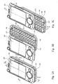
- Fig. 1A is a three-dimensional view of an electronic apparatus in a closed state according to one embodiment of the present invention.
- the electronic apparatus includes a display device 130, a first electronic module 110, a second electronic module 120 and a keyboard 140 (shown in Figs. 1B and 1C ).
- the display device 130 is configured on an upper surface 114 of the first electronic module 110.
- the keyboard 140 is configured on an upper surface 124 of the second electronic module 120.
- the first electronic module 110 partially conceals the keyboard 140 when the electronic apparatus is in the closed state.
- Figs. 1B and 1C are three-dimensional views of the electronic apparatus of Fig. 1A , showing the electronic apparatus in a first open state and a second open state, respectively.
- the keyboard 140 may include a full-text input portion 142 and a dial number input portion 144.
- the full-text input portion 142 of the keyboard 140 is exposed when the electronic apparatus is in the first open state (as shown in Fig. 1 B) .
- the dial number input portion 144 of the keyboard 140 is exposed when the electronic apparatus is in the second open state (as shown in Fig. 1 C) .
- the present embodiment provides a flexible circuit board.
- the structure and the operation of the flexible circuit board will be illustrated with reference to the drawings hereinafter.
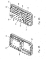
- FIG. 2A shows the electronic apparatus of Fig. 1A after its display device is removed
- Fig. 2B shows the electronic apparatus of Fig. 1A after its display device and first electronic module is removed
- a flexible circuit board 150 for the electronic apparatus includes a first connecting part 152 and a second connecting part 154.
- the first connecting part 152 has a first connecting terminal 153 electrically connected to the first electronic module 110.
- the second connecting part 154 has a second connecting terminal 155 electrically connected to the second electronic module 120.
- the first connecting part 152 and the second connecting part 154 are not parallel.
- first connecting part 152 and the second connecting part 154 are substantially vertical, but it can be easily understood that the angle between the first connecting part 152 and the second connecting part 154 may be other degree(s) as well.
- the flexible circuit board 150 may have a curved portion 159 connecting the first connecting part 152 and the second connecting part 154.
- the first connecting terminal 153 moves relative to the second connecting part 154 when the first electronic module 110 is slid relative to the second electronic module 120 between the closed state and the first open state.
- the following will illustrate how the first connecting terminal 153 moves relative to the second connecting part 154 with reference to the drawings.
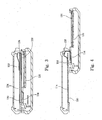
- Fig. 3 is a sectional view of the electronic apparatus of Fig. 1A taken on line 3-3
- Fig. 4 is a sectional view of the electronic apparatus of Fig. 1B taken on line 4-4.
- the first connecting terminal 153 approaches the second connecting part 154 when the first electronic module 110 is slid relative to the second electronic module 120 from the closed state to the first open state.
- the first connecting terminal 153 leaves the second connecting part 154 when the first electronic module 110 is slid relative to the second electronic module 120 from the first open state to the closed state.
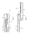
- Figs. 5 and 6 are sectional views of the electronic apparatus according to another embodiment of the present invention similar as taken on line 3-3 as shown in Fig. 1A and line 4-4 as shown in Fig. 1B , showing the electronic apparatus in the closed state and the first open state, respectively.
- the first connecting terminal 153 leaves the second connecting part 154 when the first electronic module 110 is slid relative to the second electronic module 120 from the closed state to the first open state.
- the first connecting terminal 153 approaches the second connecting part 154 when the first electronic module 110 is slid relative to the second electronic module 120 from the first open state to the closed state.
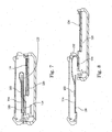
- Figs. 7 and 8 are sectional views of the electronic apparatus according to yet another embodiment of the present invention similar as taken on line 3-3 as shown in Fig. 1A and line 4-4 as shown in Fig. 1B , showing the electronic apparatus in the closed state and the first open state, respectively.
- the first connecting terminal 153 moves across the second connecting part 154 when the first electronic module 110 is slid relative to the second electronic module 120 from the closed state to the first open state.
- the first connecting terminal 153 moves across the second connecting part 154 when the first electronic module 110 is slid relative to the second electronic module 120 from the first open state to the closed state.
- the second connecting terminal 155 may also move relative to the first connecting part 152 when the first electronic module 110 is slid relative to the second electronic module 120 between the closed state and the second open state. The following will illustrate how the second connecting terminal 155 moves relative to the first connecting part 152 with reference to the drawings.
- Fig. 9 is a sectional view of the electronic apparatus of Fig. 1A taken on line 9-9
- Fig. 10 is a sectional view of the electronic apparatus of Fig. 1C taken on line 10-10.
- the second connecting terminal 155 approaches the first connecting part 152 when the first electronic module 110 is slid relative to the second electronic module 120 from the closed state to the second open state.
- the second connecting terminal 155 leaves the first connecting part 152 when the first electronic module 110 is slid relative to the second electronic module 120 from the second open state to the closed state.
- Figs. 11 and 12 are sectional views of the electronic apparatus according to another embodiment of the present invention similar as taken on line 9-9 as shown in Fig. 1A and line 10-10 as shown in Fig. 1C , showing the electronic apparatus in the closed state and the second open state, respectively.
- the second connecting terminal 155 leaves the first connecting part 152 when the first electronic module 110 is slid relative to the second electronic module 120 from the closed state to the second open state.
- the second connecting terminal 155 approaches the first connecting part 152 when the first electronic module 110 is slid relative to the second electronic module 120 from the second open state to the closed state.
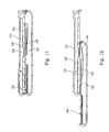
- Figs. 13 and 14 are sectional views of the electronic apparatus according to yet another embodiment of the present invention similar as taken on line 9-9 as shown in Fig. 1A and line 10-10 as shown in Fig. 1C , showing the electronic apparatus in the closed state and the second open state, respectively.
- the second connecting terminal 155 moves across the first connecting part 152 when the first electronic module 110 is slid relative to the second electronic module 120 from the closed state to the second open state.
- the second connecting terminal 155 moves across the first connecting part 152 when the first electronic module 110 is slid relative to the second electronic module 120 from the second open state to the closed state.
- the first electronic module 110 may be slid in a first direction I relative to the second electronic module 120 between the closed state and the first open state (as shown in Figs. 1A and 1B ), and length direction of the first connecting part 152 (shown in Fig. 2B ) may be substantially parallel with the first direction I.
- the first electronic module 110 may be slid in a second direction II relative to the second electronic module 120 between the closed state and the second open state (as shown in Figs. 1A and 1C ), and length direction of the second connecting part 154 (shown in Fig. 2B ) may be substantially parallel with the second direction II.
- first direction I and the second direction II may be separated at an angle of about 90°. That is, length direction of the first connecting part 152 (shown in Fig. 2B ) and length direction of the second connecting part 154 (shown in Fig. 2B ) may be separated at an angle of about 90° as well. It is simply understood that the above mentioned angle (degrees) is only an example. In fact, the angle between the first direction I and the second direction II (i.e. the angle between length direction of the first connecting part 152 and length direction of the second connecting part 154) may be other degree(s) as well.
- the first electronic module 110 may conceal the flexible circuit board to improve the aesthetic appeal of the electronic apparatus when the display device 130 is exposed and the electronic apparatus is in the closed state, the first open state or the second open state.
- Fig. 15 is a sectional view of the electronic apparatus of Fig. 1A taken on line 15-15.
- the first connecting part 152 may have a first curved part 156 providing the first connecting part 152 with a C shaped profile or a lying J shaped profile.
- the first electronic module 110 may have an opening 112, and the first connecting terminal 153 of the first connecting part 152 may be electrically connected to the first electronic module 110 through the opening 112.
- the second connecting part 154 may also have a second curved part 157 providing the second connecting part 154 with a C shaped profile or a lying J shaped profile.
- the second electronic module 120 may have an opening 122, and the second connecting terminal 155 of the second connecting part 154 may be electrically connected to the second electronic module 120 through the opening 122.
- the electronic apparatus of the above embodiments employs the flexible circuit board to be slid open/close in at least two directions. That is, the flexible circuit board can electrically connect the electronic modules of the electronic apparatus during the sliding operation. Furthermore, the first connecting part and the second connecting part of the flexible circuit board are located on the same plane, and thus only two electronic modules is needed to achieve sliding open/close in different directions. Accordingly, the electronic apparatus of the above embodiments will have a thinner thickness and a smaller size than the conventional PDA cell phone,
Landscapes
- Engineering & Computer Science (AREA)
- Signal Processing (AREA)
- Telephone Set Structure (AREA)
- Combinations Of Printed Boards (AREA)
Claims (13)
- Elektronische Vorrichtung, umfassend:ein erstes elektronisches Modul (110),ein zweites elektronisches Modul (120), das unter dem ersten elektronischen Modul (110) derart angeordnet ist, dass das zweite elektronische Modul (120) relativ zum ersten elektronischen Modul (110) verschoben werden kann, um einen geschlossenen Zustand, einen ersten offenen Zustand und einen zweiten offenen Zustand auszubilden undeine flexible Leiterplatte (150), die zwischen dem ersten elektronischen Modul (110) und dem zweiten elektronischen Modul (120) angeordnet ist und umfasst:einen ersten Verbindungsabschnitt (152), mit einem ersten Verbindungsanschluss (153), der elektrisch mit dem ersten elektronischen Modul (110) verbunden ist, und einen zweiten Verbindungsabschnitt (154), mit einem zweiten Verbindungsanschluss (155), der elektrisch mit dem zweiten elektronischen Modul (120) derart verbunden ist, dass das erste elektronisches Modul (110) elektrisch mit dem zweiten elektronischen Modul (120) verbunden ist, wobei der erste Verbindungsabschnitt (152) und der zweite Verbindungsabschnitt (154) nicht derart parallel zueinander angeordnet sind, dass sich der erste Verbindungsabschnitt (153) bzgl. des zweiten Verbindungsabschnittes (154) bewegt, wenn das erste elektronische Modul (110) bzgl. des zweiten elektronischen Moduls (120) zwischen dem geschlossenen Zustand und dem ersten offenen Zustand verschoben wird und der zweite Verbindungsanschluss (155) sich bzgl. des ersten Verbindungsabschnittes (152) bewegt, wenn das erste elektronische Modul (110) bzgl. des zweiten elektronischen Moduls (120) zwischen dem geschlossenen Zustand und dem zweiten offenen Zustand verschoben wird,dadurch gekennzeichnet,dass die flexible Leiterplatte (150) einen gebogenen Abschnitt (159) umfasst, der den ersten Verbindungsabschnitt (152) und den zweiten Verbindungsabschnitt (154) miteinander verbindet.
- Elektronische Vorrichtung gemäß Anspruch 1, wobei das erste elektronische Modul (110) in eine erste Richtung bzgl. des zweiten elektronischen Moduls (120) verschoben wird, um den geschlossenen Zustand und den ersten offenen Zustand auszubilden und das erste elektronische Modul (110) in eine zweite Richtung bzgl. des zweiten elektronischen Moduls (120) verschiebbar ist, um den geschlossenen Zustand und den zweiten offenen Zustand auszubilden.
- Elektronische Vorrichtung gemäß Anspruch 2, wobei die erste Richtung und die zweite Richtung unter einem Winkel von 90 Grad zueinander angeordnet sind.
- Elektronische Vorrichtung nach Anspruch 2 oder 3, wobei eine Längsrichtung des ersten Verbindungsabschnittes (152) im Wesentlichen parallel zur ersten Richtung ist.
- Elektronische Vorrichtung nach einem der Ansprüche 2, 3 oder 4, wobei eine Längsrichtung des zweiten Verbindungsabschnittes (154) im Wesentlichen parallel zur zweiten Richtung ist.
- Elektronische Vorrichtung nach einem der Ansprüche 1 bis 5, wobei eine Längsrichtung des ersten Verbindungsabschnittes (152) und eine Längsrichtung des zweiten Verbindungsabschnittes (154) unter einem Winkel von etwa 90 Grad zueinander angeordnet sind.
- Elektronische Vorrichtung nach einem der Ansprüche 1 bis 6, wobei der erste Verbindungsabschnitt (152) einen ersten gebogenen Abschnitt aufweist, der den ersten Verbindungsabschnitt (152) mit einem C-förmig ausgebildeten Profil oder einem liegenden J-förmigen Profil versieht.
- Elektronische Vorrichtung nach Anspruch 7, wobei das erste elektronische Modul (110) eine Öffnung aufweist und der erste Verbindungsanschluss (153) des ersten Verbindungsabschnittes (152) elektrisch mit dem ersten elektronischen Modul (110) durch die Öffnung verbunden ist.
- Elektronische Vorrichtung nach einem der Ansprüche 1 bis 8, wobei der zweite Verbindungsabschnitt (154) einen gewölbten Abschnitt aufweist, der den zweiten Verbindungsabschnitt (154) mit einem C-förmigen Profil oder einem liegenden J-förmigen Profil versieht.
- Elektronische Vorrichtung nach Anspruch 9, wobei das zweite elektronische Modul (120) eine Öffnung aufweist und der zweite Verbindungsanschluss (155) des zweiten Verbindungsabschnittes (154) über die Öffnung elektrisch mit dem zweiten elektronischen Modul (120) verbunden ist.
- Elektronische Vorrichtung nach einem der Ansprüche 1 bis 10, weiterhin umfassend, eine Anzeigeeinrichtung (130), die auf einer oberen Oberfläche des ersten elektronischen Moduls (110) ausgebildet ist, und
eine Tastatur (140), die an einer oberen Oberfläche des zweiten elektronischen Moduls (120) ausgebildet ist, wobei das erste elektronische Modul (110) teilweise die Tastatur (140) verdeckt, wenn die elektronische Vorrichtung im geschlossenen Zustand ist. - Elektronische Vorrichtung nach Anspruch 11, wobei die Tastatur (140) einen Volltexteingabeabschnitt (142) aufweist und der Volltexteingabeabschnitt der Tastatur (140) freigelegt ist, wenn die elektronische Vorrichtung im ersten offenen Zustand ist.
- Elektronische Vorrichtung nach Anspruch 11 oder 12, wobei die Tastatur (140) einen Wählnummerneingabeabschnitt (144) aufweist und der Wählnummerneingabeabschnitt der Tastatur freigelegt ist, wenn die elektronische Vorrichtung im zweiten offenen Zustand ist.
Applications Claiming Priority (1)
| Application Number | Priority Date | Filing Date | Title |
|---|---|---|---|
| TW096127144A TWI351209B (en) | 2007-07-25 | 2007-07-25 | Electronic apparatus and flexible printed circuit board thereof |
Publications (3)
| Publication Number | Publication Date |
|---|---|
| EP2019537A2 EP2019537A2 (de) | 2009-01-28 |
| EP2019537A3 EP2019537A3 (de) | 2009-03-25 |
| EP2019537B1 true EP2019537B1 (de) | 2010-05-12 |
Family
ID=39832315
Family Applications (1)
| Application Number | Title | Priority Date | Filing Date |
|---|---|---|---|
| EP08157535A Ceased EP2019537B1 (de) | 2007-07-25 | 2008-06-04 | Elektronische Vorrichtung und flexible Schaltplatte |
Country Status (4)
| Country | Link |
|---|---|
| US (1) | US7996052B2 (de) |
| EP (1) | EP2019537B1 (de) |
| DE (1) | DE602008001212D1 (de) |
| TW (1) | TWI351209B (de) |
Families Citing this family (12)
| Publication number | Priority date | Publication date | Assignee | Title |
|---|---|---|---|---|
| TWI387427B (zh) * | 2009-01-22 | 2013-02-21 | Asustek Comp Inc | 手持電子裝置 |
| TWI424804B (zh) * | 2009-09-02 | 2014-01-21 | 宏達國際電子股份有限公司 | 電子裝置及其連接機構 |
| CN102014178B (zh) * | 2009-09-04 | 2013-07-31 | 宏达国际电子股份有限公司 | 电子装置 |
| CN102014177B (zh) * | 2009-09-04 | 2013-09-11 | 宏达国际电子股份有限公司 | 电子装置 |
| US8749962B2 (en) * | 2011-02-07 | 2014-06-10 | Qualcomm Incorporated | Keypad assembly with a contoured keypad facade for a mobile computing device |
| TWI429375B (zh) * | 2011-11-18 | 2014-03-01 | Wistron Corp | 具有軟性電路板導引機構之電子裝置 |
| US20130163158A1 (en) * | 2011-12-02 | 2013-06-27 | Sony Mobile Communications Japan, Inc. | Terminal apparatus |
| KR102216674B1 (ko) * | 2014-02-10 | 2021-02-18 | 삼성디스플레이 주식회사 | 폴딩 가능한 디스플레이 장치 |
| USD896809S1 (en) * | 2018-02-28 | 2020-09-22 | Shenzhen Hastech Industries Co., Ltd. | Bluetooth keyboard |
| USD902928S1 (en) * | 2018-07-12 | 2020-11-24 | Shenzhen Hastech Industries Co., Ltd. | Bluetooth keyboard |
| USD925534S1 (en) * | 2020-02-18 | 2021-07-20 | Wen Ma | Air mouse keyboard |
| USD1038128S1 (en) * | 2021-10-08 | 2024-08-06 | Shenzhen Sqt Electronics Co., Ltd. | Keyboard |
Family Cites Families (6)
| Publication number | Priority date | Publication date | Assignee | Title |
|---|---|---|---|---|
| AUPN755196A0 (en) * | 1996-01-15 | 1996-02-08 | Benson, Keith | Improvements relating to mobile phones |
| KR100721337B1 (ko) * | 2004-12-22 | 2007-05-28 | 엘지전자 주식회사 | 사이드 슬라이딩형 전자장치 |
| US20070142101A1 (en) * | 2005-08-23 | 2007-06-21 | Sudhir Seshagiri | Mobile electronic device having a rotatable keypad |
| KR100810263B1 (ko) * | 2005-10-11 | 2008-03-07 | 삼성전자주식회사 | 휴대용 단말기의 키패드, 슬라이딩 모듈 및 그의 연성 회로 |
| US7520781B2 (en) * | 2006-03-08 | 2009-04-21 | Microelectronics Assembly Technologies | Thin multichip flex-module |
| US7596396B2 (en) * | 2006-05-26 | 2009-09-29 | Sony Ericsson Mobile Communications Ab | Flexible gaskets for wireless terminals with sliding members |
-
2007
- 2007-07-25 TW TW096127144A patent/TWI351209B/zh not_active IP Right Cessation
-
2008
- 2008-06-04 DE DE602008001212T patent/DE602008001212D1/de active Active
- 2008-06-04 EP EP08157535A patent/EP2019537B1/de not_active Ceased
- 2008-06-13 US US12/157,750 patent/US7996052B2/en not_active Expired - Fee Related
Also Published As
| Publication number | Publication date |
|---|---|
| EP2019537A3 (de) | 2009-03-25 |
| DE602008001212D1 (de) | 2010-06-24 |
| EP2019537A2 (de) | 2009-01-28 |
| US7996052B2 (en) | 2011-08-09 |
| TWI351209B (en) | 2011-10-21 |
| US20090027841A1 (en) | 2009-01-29 |
| TW200906137A (en) | 2009-02-01 |
Similar Documents
| Publication | Publication Date | Title |
|---|---|---|
| US7996052B2 (en) | Electronic apparatus and flexible circuit board | |
| EP1720326B1 (de) | Tragbares Endgerät mit zwei Gehäusen die sowohl faltbar als auch ausziehbar relativ zueinander sind | |
| EP1587284B1 (de) | Tragbares Endgerät mit touch key | |
| CN1997042B (zh) | 具有两个键区的移动通信终端 | |
| US8060155B2 (en) | Port cover opening/closing device for portable terminal | |
| EP2014063B1 (de) | Bidirektional verschiebbares mobiles endgerät | |
| EP1806909B1 (de) | Tragbares Kommunikationsendgerät für Spiele und Benutzerschnittstellenvorrichtung dafür | |
| CN100534109C (zh) | 使用柔性材料的滑动型便携式终端 | |
| EP2288119A1 (de) | Tragbares Informationsendgerät | |
| US7697270B2 (en) | Portable electronic device | |
| EP2223511A1 (de) | Gleitmechanismus | |
| EP1739931B1 (de) | Tragbares Endgerät mit verschiebbaren und klappbaren Gehäusen | |
| EP1528758B1 (de) | Synchronisierte Schiebevorrichtung für eine geteilte Tastatur eines mobilen Endgerätes und ein Verfahren zu deren Nutzung | |
| US20070115255A1 (en) | Mobile device | |
| EP1770965B1 (de) | Mobiles Endgerät mit einer Mehrzahl von ausziehbaren Tastaturen | |
| US7458833B2 (en) | Inseparable PCB module in a sub body of a device | |
| EP1843555B1 (de) | Dünnes tragbares Endgerät | |
| CN101460032B (zh) | 手持式电子装置 | |
| CN101686624B (zh) | 手持电子装置 | |
| US8253045B2 (en) | Keypad assembly and electronic device using same | |
| JP4808554B2 (ja) | 無線通信端末 | |
| US8227717B2 (en) | Key mechanism and electronic device using the same | |
| CN101355860A (zh) | 电子装置及其软性电路板 | |
| KR100754600B1 (ko) | 휴대 단말기의 표시 장치용 결합장치 | |
| US20100124944A1 (en) | Mobile communications device with slidable and pivotable screen |
Legal Events
| Date | Code | Title | Description |
|---|---|---|---|
| PUAI | Public reference made under article 153(3) epc to a published international application that has entered the european phase |
Free format text: ORIGINAL CODE: 0009012 |
|
| 17P | Request for examination filed |
Effective date: 20081031 |
|
| AK | Designated contracting states |
Kind code of ref document: A2 Designated state(s): AT BE BG CH CY CZ DE DK EE ES FI FR GB GR HR HU IE IS IT LI LT LU LV MC MT NL NO PL PT RO SE SI SK TR |
|
| AX | Request for extension of the european patent |
Extension state: AL BA MK RS |
|
| PUAL | Search report despatched |
Free format text: ORIGINAL CODE: 0009013 |
|
| AK | Designated contracting states |
Kind code of ref document: A3 Designated state(s): AT BE BG CH CY CZ DE DK EE ES FI FR GB GR HR HU IE IS IT LI LT LU LV MC MT NL NO PL PT RO SE SI SK TR |
|
| AX | Request for extension of the european patent |
Extension state: AL BA MK RS |
|
| GRAP | Despatch of communication of intention to grant a patent |
Free format text: ORIGINAL CODE: EPIDOSNIGR1 |
|
| AKX | Designation fees paid |
Designated state(s): DE FR GB NL |
|
| GRAS | Grant fee paid |
Free format text: ORIGINAL CODE: EPIDOSNIGR3 |
|
| GRAA | (expected) grant |
Free format text: ORIGINAL CODE: 0009210 |
|
| RAP1 | Party data changed (applicant data changed or rights of an application transferred) |
Owner name: HTC CORPORATION |
|
| AK | Designated contracting states |
Kind code of ref document: B1 Designated state(s): DE FR GB NL |
|
| REG | Reference to a national code |
Ref country code: GB Ref legal event code: FG4D |
|
| REF | Corresponds to: |
Ref document number: 602008001212 Country of ref document: DE Date of ref document: 20100624 Kind code of ref document: P |
|
| REG | Reference to a national code |
Ref country code: NL Ref legal event code: T3 |
|
| PLBE | No opposition filed within time limit |
Free format text: ORIGINAL CODE: 0009261 |
|
| STAA | Information on the status of an ep patent application or granted ep patent |
Free format text: STATUS: NO OPPOSITION FILED WITHIN TIME LIMIT |
|
| 26N | No opposition filed |
Effective date: 20110215 |
|
| REG | Reference to a national code |
Ref country code: DE Ref legal event code: R097 Ref document number: 602008001212 Country of ref document: DE Effective date: 20110214 |
|
| REG | Reference to a national code |
Ref country code: DE Ref legal event code: R082 Ref document number: 602008001212 Country of ref document: DE Representative=s name: PATRONUS IP PATENT- & RECHTSANWAELTE BERNHARD , DE |
|
| REG | Reference to a national code |
Ref country code: FR Ref legal event code: PLFP Year of fee payment: 9 |
|
| REG | Reference to a national code |
Ref country code: FR Ref legal event code: PLFP Year of fee payment: 10 |
|
| REG | Reference to a national code |
Ref country code: FR Ref legal event code: PLFP Year of fee payment: 11 |
|
| PGFP | Annual fee paid to national office [announced via postgrant information from national office to epo] |
Ref country code: NL Payment date: 20190515 Year of fee payment: 12 |
|
| PGFP | Annual fee paid to national office [announced via postgrant information from national office to epo] |
Ref country code: DE Payment date: 20190521 Year of fee payment: 12 |
|
| PGFP | Annual fee paid to national office [announced via postgrant information from national office to epo] |
Ref country code: FR Payment date: 20190410 Year of fee payment: 12 |
|
| PGFP | Annual fee paid to national office [announced via postgrant information from national office to epo] |
Ref country code: GB Payment date: 20190529 Year of fee payment: 12 |
|
| REG | Reference to a national code |
Ref country code: DE Ref legal event code: R119 Ref document number: 602008001212 Country of ref document: DE |
|
| REG | Reference to a national code |
Ref country code: NL Ref legal event code: MM Effective date: 20200701 |
|
| GBPC | Gb: european patent ceased through non-payment of renewal fee |
Effective date: 20200604 |
|
| PG25 | Lapsed in a contracting state [announced via postgrant information from national office to epo] |
Ref country code: FR Free format text: LAPSE BECAUSE OF NON-PAYMENT OF DUE FEES Effective date: 20200630 Ref country code: GB Free format text: LAPSE BECAUSE OF NON-PAYMENT OF DUE FEES Effective date: 20200604 Ref country code: NL Free format text: LAPSE BECAUSE OF NON-PAYMENT OF DUE FEES Effective date: 20200701 |
|
| PG25 | Lapsed in a contracting state [announced via postgrant information from national office to epo] |
Ref country code: DE Free format text: LAPSE BECAUSE OF NON-PAYMENT OF DUE FEES Effective date: 20210101 |