EP1528758B1 - Synchronisierte Schiebevorrichtung für eine geteilte Tastatur eines mobilen Endgerätes und ein Verfahren zu deren Nutzung - Google Patents
Synchronisierte Schiebevorrichtung für eine geteilte Tastatur eines mobilen Endgerätes und ein Verfahren zu deren Nutzung Download PDFInfo
- Publication number
- EP1528758B1 EP1528758B1 EP04025940A EP04025940A EP1528758B1 EP 1528758 B1 EP1528758 B1 EP 1528758B1 EP 04025940 A EP04025940 A EP 04025940A EP 04025940 A EP04025940 A EP 04025940A EP 1528758 B1 EP1528758 B1 EP 1528758B1
- Authority
- EP
- European Patent Office
- Prior art keywords
- sub
- housing
- sliding
- slide
- housings
- Prior art date
- Legal status (The legal status is an assumption and is not a legal conclusion. Google has not performed a legal analysis and makes no representation as to the accuracy of the status listed.)
- Expired - Lifetime
Links
Images


Classifications
-
- H—ELECTRICITY
- H04—ELECTRIC COMMUNICATION TECHNIQUE
- H04B—TRANSMISSION
- H04B1/00—Details of transmission systems, not covered by a single one of groups H04B3/00 - H04B13/00; Details of transmission systems not characterised by the medium used for transmission
- H04B1/38—Transceivers, i.e. devices in which transmitter and receiver form a structural unit and in which at least one part is used for functions of transmitting and receiving
- H04B1/40—Circuits
-
- H—ELECTRICITY
- H04—ELECTRIC COMMUNICATION TECHNIQUE
- H04M—TELEPHONIC COMMUNICATION
- H04M1/00—Substation equipment, e.g. for use by subscribers
- H04M1/02—Constructional features of telephone sets
- H04M1/0202—Portable telephone sets, e.g. cordless phones, mobile phones or bar type handsets
- H04M1/0206—Portable telephones comprising a plurality of mechanically joined movable body parts, e.g. hinged housings
- H04M1/0247—Portable telephones comprising a plurality of mechanically joined movable body parts, e.g. hinged housings comprising more than two body parts
-
- H—ELECTRICITY
- H04—ELECTRIC COMMUNICATION TECHNIQUE
- H04M—TELEPHONIC COMMUNICATION
- H04M1/00—Substation equipment, e.g. for use by subscribers
- H04M1/02—Constructional features of telephone sets
- H04M1/23—Construction or mounting of dials or of equivalent devices; Means for facilitating the use thereof
-
- H—ELECTRICITY
- H04—ELECTRIC COMMUNICATION TECHNIQUE
- H04M—TELEPHONIC COMMUNICATION
- H04M1/00—Substation equipment, e.g. for use by subscribers
- H04M1/02—Constructional features of telephone sets
- H04M1/0202—Portable telephone sets, e.g. cordless phones, mobile phones or bar type handsets
- H04M1/0206—Portable telephones comprising a plurality of mechanically joined movable body parts, e.g. hinged housings
- H04M1/0208—Portable telephones comprising a plurality of mechanically joined movable body parts, e.g. hinged housings characterized by the relative motions of the body parts
- H04M1/0235—Slidable or telescopic telephones, i.e. with a relative translation movement of the body parts; Telephones using a combination of translation and other relative motions of the body parts
- H04M1/0237—Sliding mechanism with one degree of freedom
Definitions
- the present invention relates to mobile terminals, such as cellular phones, PDAs (Personal Digital Assistants), HHPs (Handheld Phones), etc. More particularly, the present invention relates to a mobile terminal, which comprises a pair of sub-housings slidably movable on a main housing, and a sliding module of the mobile terminal and a method of sliding the sub-housings thereof.
- the term "mobile terminal” means an electronic apparatus, which allows a user to perform wireless communication with others in a handheld state.
- mobile terminals have been designed to achieve miniaturization, slimness, and lighter weight to increase portability.
- mobile terminals have been increasingly developed to support multimedia applications, which can provide various functions.
- the mobile terminals have been both miniaturized and reduced in weight, as well as used for multi-function and multipurpose applications.
- the mobile terminals have been adapted to be appropriate for a variety of multimedia environments or Internet environments. Regardless of users' sex or age, mobile terminals are now used worldwide, and are viewed as a necessity of life, to be carried at all times.
- the mobile terminals can be classified into various types according to appearance.
- the mobile terminals can be classified into a bar-type terminal, a flip-type terminal, or a folder-type terminal according to their appearances.
- the bar-type terminal means a terminal having a bar-shaped single housing
- the flip-type terminal means a terminal having a flip member rotatably coupled to the bar-shaped housing by a hinge member
- the folder-type terminal means a terminal having a folder rotatably coupled to the bar-shaped housing by a hinge member.
- the conventional mobile terminals can be classified into a neck wearable type terminal and a wrist wearable type terminal according to how the terminal is worn, and can be classified into a rotational type terminal and a sliding type terminal according to the opening and closing method thereof.
- These mobile terminals variously classified as mentioned above, can be easily understood by those skilled in the art of the present invention.
- the mobile terminals have been developed to have a structure that allows high-speed data communication, as well as voice communication. That is, according to the increasing demands of users, the mobile terminals will be adapted to supply various services employing wireless communication technology that transmits data at high speed.
- the conventional mobile terminal is provided with a screen that is too small for the new services offered to the users, e.g. web browsing.
- This problem of lack of space resulting of the miniaturisation of electronic devices has been addressed in document EP 1051012 , in which a portable electronic device, which has a slidingly attached touch screen and a sliding lid also slidingly installed on top of the touch screen.
- a keyboard is installed on top of the sliding lid.
- the display of the device is partly covered by the sliding lid and, thus, protected by the sliding lid against mechanical stress.
- the display can be revealed by moving the sliding lid away from the display, whereupon a cogging made on the bottom of the sliding lid rotates a cogwheel, attached inside the device that touches the cogging.
- the cogwheel transmits the movement of the sliding lid to a movement that is opposite to that of the sliding lid of the display, through a gear rack attached to the display.
- the device can again be brought to the normal state by moving the sliding lid back on top of the display or the display to underneath the sliding lid, whereupon the cogged surfaces that touch against each other cause the remaining moving element to move, and again bring the device to the normal state. Therefore, a larger display can be installed in such a device.
- the conventional mobile terminal is provided with a restricted input means, for example, a keypad.
- a restricted input means for example, a keypad.
- a solution is proposed in US Patent 2003/0103041 A1 in which, a handheld data processing device having three functional components are assembled in a sliding configuration.
- a processor module is mechanically coupled to two sliding covers.
- the processor module houses circuits for performing the functions of data processing and may also include a display and input/output functionality.
- the two sliding covers provide protection for the processor module and may include input/output transducers such as a keypad, speaker or microphone. Therefore an enriched keypad can be provided to the mobile electronic device.
- an object of the invention is to provide a mobile terminal with a pair of sub-housings slidably moving away in opposite directions, allowing an expanded keypad to be installed in the mobile terminal, and a sliding module of the mobile terminal.
- this object is accomplished by providing a sliding module for a mobile terminal comprising: a main housing; and first and second sub-housings, each slidably mounted on an upper surface of the main housing such that the first and second sub-housings can slide towards each other or away from each other to open and, therefore, uncover or close and, therefore, cover a predetermined region of the upper surface of the main housing, wherein the sliding module is provided with slide links, each being equipped on the main housing to slidably move thereon in a state that the slide links face each other and having one end fixed to one of the first and second sub-housings while being interlinked to the other slide link by means of a predetermined gear such that the one end of the slide link can move towards the other slide link or away therefrom.
- a mobile terminal comprising: a main housing having an opening, provided at the center of the main housing to allow a display apparatus to be equipped therein, and at least one pair of guide holes symmetrically elongated in a longitudinal direction at both sides of the opening centered on the opening while penetrating the main housing; first and second sub-housings, each being slidably mounted on an upper surface of the main housing with one or more guide protrusions linearly moving within the guide holes provided on one surface of each of the sub-housings, to slidably move towards the other sub-housing or away from the other sub-housing, thereby opening or closing the display apparatus equipped on the opening of the main housing; and at least one sliding module provided with slide links, each being equipped on an inside of the main housing to slidably move thereon in a state that the slide links face each other, and having one end fixed to the guide protrusions of the first or second sub-housing while being
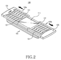
- a mobile terminal 100 having at least one sliding module 200 comprises a main housing 101, and first and second sub-housings 102a and 102b, each being slidably mounted on the upper surface of the main housing 101, to slidably move on the upper surface of the main housing 101 towards or away from each other, thereby opening (uncovering) or closing (covering) a predetermined region of the upper surface of the main housing 101.
- the first and second sub-housings 102a and 102b are mounted on the main housing 101 by means of the sliding module 200.
- a display apparatus 111 is mounted on the upper surface of the main housing 101, which is opened (uncovered) or closed (covered) by the first and second sub-housings 102a and 102b.
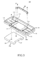
- the display apparatus 111 is mounted on the predetermined region of the upper surface of the main housing 101, specifically, on the center of the upper surface of the main housing 101. Accordingly, the main housing 101 is provided, at the center of the upper surface thereof, with an opening 113, shown in Fig. 3 , to allow the display apparatus 111 to be equipped thereto.
- the opening 113 is provided, at both sides thereof, with at least one pair of guide holes 115 symmetrically elongated in the longitudinal direction.
- the guide holes 115 penetrate the main housing 101.
- the first and second sub-housings 102a and 102b are equipped on the upper surface of the main housing 101 such that the first and second sub-housings 102a and 102b can slidably move towards each other or away from each other.
- Each of the first and second sub-housings 102a and 102b is formed, at one side thereof, with at least one guide protrusion 129.
- the guide protrusion 129 can linearly move within the corresponding guide hole 115, and has one end protruded towards an inner portion of the main housing 101.
- the first and second sub-housings 102a and 102b can slide on the upper surface of the main housing 101, respectively. Accordingly, when the first and second sub-housings 102a and 102b slide on the upper surface of the main housing 101, the predetermined region of the upper surface of the main housing 101, more specifically, the center of the main housing 101, on which the display apparatus is mounted, is opened or closed.
- Each of the first and second sub-housings 102a and 102b is provided with a keypad 121 comprising a plurality of key buttons on the upper surface of each of the first and second sub-housings. Additionally, there are provided a receiver 123 having a speaker therein, and a sender 125 having a microphone therein at preferably separate locations on the upper surface of the first and second sub-housings 102a and 102b, respectively.
- users can conduct voice communication using the mobile terminal 100.
- the users can play games using the mobile terminal 100, after opening the display apparatus 111 by sliding the first and second sub-housings 102a and 102 away from each other.
- the display apparatus 111 is provided with the keypad 121 at either side thereof, the users can conveniently operate the mobile terminal 100 with both hands to play games or to chat.
- windows 127 for exposing some portion of the display apparatus 111 may be formed on the first and second sub-housings 102a and 102b, respectively. Accordingly, with the display apparatus 111 of the mobile terminal 100 closed, the display apparatus 111 is exposed by means of the windows 127, so that the users can conveniently confirm the current time, remaining capacity of battery, existence of newly received information, and the like.
- the first and second sub-housings 102a and 102b are mounted on the main housing 101 by means of the sliding module 200.
- the sliding module 200 is mounted at an inner portion of the main housing 101, and comprises a module housing 201, slide links 204a and 204b, and a sprocket 206.
- the module housing 201 is extended in the longitudinal direction, and defines a receiving space 212, which is opened at both ends 211 of the receiving space 212.
- the module housing 201 is extended in the longitudinal direction, and is constituted by assembling first and second covers 201 a and 201b.
- each of the covers 201a and 201b is opened at both ends 211 thereof and at one side facing the opened side of the other cover. That is, the first and second covers 201a and 201b are assembled to face each other, defining the receiving space 212 of the module housing 201 opened at both ends 211.
- the first and second covers 201a and 201b are formed with coupling holes 215 and coupling protrusions 216, respectively corresponding to the coupling holes 215 to be engaged with each other, on either side thereof, respectively. Accordingly, when assembling the first and second covers 201a and 201b to face each other, the coupling holes 215 and the coupling protrusions 216 are engaged with each other, thereby completing the assembly of the module housing 201. Additionally, the first and second covers 201a and 201b are formed with grooves 213 and 214 facing each other, respectively. When assembling the first and second covers 201a and 201b, the grooves 213 and 214 are engaged with each other, forming a rotating hole 219.
- the first cover 201a is formed at one end thereof with a fastening piece 218.
- the fastening piece 218 acts to fasten the module housing 201 to an inner portion of the main housing 101. Meanwhile, although the fastening piece 218 is provided as one component in the drawings, it is noted that the shapes and the number of fastening means to fasten the module housing 201 to the main housing 101 can be variously provided.
- a pair of slide links 204a and 204b are provided to face each other within the module housing 201.
- Each of the slide links 204a and 204b is extended in the longitudinal direction, and is equipped within the module housing 201 such that the slide links 204a and 204b can be slidably moved within the module housing 201, and can be drawn from or input to the module housing 201 through both ends thereof.
- Each of the slide links 204a and 204b is formed at one end thereof with a fastening piece 241, and formed with a plurality of driving holes 243 uniformly spaced from the other end in the longitudinal direction.
- each of the slide links 204a and 204b may be formed with a supporting piece 245, which is extended in the longitudinal direction while being supported on an inner wall of the module housing 201.
- Each fastening piece 241 of the slide links 204a and 204b is fastened to the one end of the corresponding guide protrusion 129 of each of the first and second sub-housings 102a and 102b. That is, the guide protrusion 129 is exposed to the inner portion of the main housing 101 through the guide hole 115 of the main housing 101, and is then fastened to the corresponding fastening piece 241 of each of the slide links 204a and 204b. Accordingly, when the user slides the first and second sub-housings 102a and 102b, the slide links 204a and 204b slide in the longitudinal direction of the module housing 201.
- the sprocket 206 is rotatably mounted between the pair of slide links 204a and 204b, and is formed with a plurality of driving pins 261 uniformly spaced on an outer peripheral surface of the sprocket 206 to be engaged with the driving holes 243. Accordingly, when one of the slide links 204a is slidingly moved, the sprocket 206 is rotated corresponding to the sliding movement of the slide links 204a, causing the other slide link 204b to be slidingly moved.
- the sprocket 206 is formed with a rotating protrusion 263 at either side of the sprocket 206 such that the rotating protrusion 263 can be rotatably coupled to the rotating hole 219 of the module housing 201.
- the module housing 201 is formed at upper and lower surfaces thereof with receiving holes 217, respectively.
- the pairs of slide links 204a and 204b are interlinked with each other by means of a gear constituted by the driving holes 243 and the sprocket 206 having the driving pins 261 formed thereon.
- a gear constituted by the driving holes 243 and the sprocket 206 having the driving pins 261 formed thereon When one of the sub-housings 102a and 102b is slidingly moved, one of the slide links 204a and 204b coupled to the corresponding guide protrusion 129 is also slidingly moved, thereby rotating the sprocket 206.
- the sprocket 206 is rotated, the other slide link is slidingly moved according to a rotational direction of the sprocket 206, causing the other sub-housing to be rotated. For instance, as shown in Fig.
- the sliding module 200 constructed as described above is fastened to the inner portion of the main housing 101.
- a pair of sliding module 200 may be symmetrically positioned at opposite edges of the openings 113.
- the fastening pieces 241 of the slide links 204a and 204a; 204b and 204b, facing each other and symmetrically positioned at both sides of the openings 113 are fastened to supporting pieces 119, so that the fastening pieces 241 of the slide links 204a and 204a; 204b and 204b are connected to each other by means of each of the supporting piece 119.
- the mobile terminal of the present invention is provided with the first and second sub-housings designed to slide on the main housing towards each other or away from each other to open or close the display apparatus, thereby allowing easy operation of the keypads provided at both sides of the display apparatus with both hands when the display apparatus is open, resulting in convenience of playing games or chatting.
- the first and second sub-housings are interlinked with each other though the sliding modules, such that, when moving only one sub-housing, the other sub-housing can also be moved, thereby allowing easy opening closing of the display apparatus.
Landscapes
- Engineering & Computer Science (AREA)
- Signal Processing (AREA)
- Computer Networks & Wireless Communication (AREA)
- Telephone Set Structure (AREA)
- Casings For Electric Apparatus (AREA)
Claims (19)
- Schiebermodul (200) für ein mobiles Endgerät (100), aufweisend:ein Hauptgehäuse (101);ein erstes und ein zweites Untergehäuse (102a, 102b), die jeweils verschiebbar auf einer oberen Oberfläche des Hauptgehäuses (101) befestigt sind, so dass das erste und das zweite Untergehäuse (102a, 102b) eingerichtet sind, zueinander oder voneinander weg verschoben zu werden, um einen vorbestimmten Bereich der oberen Oberfläche des Hauptgehäuses (101) zu öffnen oder zu schließen,wobei das Schiebermodul (200) mit Schiebergliedern (204a, 204b) versehen ist, die jeweils auf dem Hauptgehäuse (101) ausgestattet sind, um darauf verschiebbar sich zu bewegen in einem Zustand, in dem die Schieberglieder (204a, 204b) sich gegenüberliegen, und eines der Schieberglieder (204a oder 204b) mit einem Ende befestigt ist an einem des ersten und des zweiten Untergehäuses (102a, 102b), während es mit dem anderen Schieberglied verkettet ist über ein vorbestimmtes Ritzel bzw. Getriebe, sodass das eine Ende des Schiebergliedes sich zu dem anderen Schieberglied hinbewegen oder von dem anderen Schieberglied wegbewegen kann,dadurch gekennzeichnet, dassdas Schiebermodul (200) ferner mit einem Modulgehäuse 201 versehen ist, das sich in die Längsrichtung erstreckt und zu beiden Enden (211) des Modulgehäuses (201) geöffnet ist, wobei jedes der Schieberglieder (204a, 204b) sich durch eines der Enden (211) hindurch erstreckt und angeordnet ist, sich innerhalb des Modulgehäuses verschiebbar zu bewegen.
- Schiebermodul (200) nach Anspruch 1, worin jedes der Schieberglieder (204a, 204b) an einem Ende davon mit einem Befestigungsstück (218) gebildet ist, das an das erste (102a) oder das zweite Untergehäuse (1 02b) befestigt ist.
- Schiebermodul (200) nach Anspruch 1, worin das Getriebe aufweist:eine Mehrzahl von Antriebslöchem (243), gleichförmig beabstandet von dem anderen Ende von jedem der Schieberglieder (204a, 204b) in einer Längsrichtung; undein Zahnrad (206), das drehbar befestigt ist zwischen dem Paar von Schiebergliedern (204a, 204b), ausgebildet mit einer Vielzahl von Antriebsstiften (261), die gleichförmig beabstandet sind an einer äußeren Umfangsfläche des Zahnrads (206), um in die Antriebslöcher einzugreifen, so dass, wenn eines der Schieberglieder (204a, 204b) verschiebend bewegt wird, das Zahnrad (206) entsprechend einer Verschiebebewegung des Schiebergliedes gedreht wird, was verursacht, dass das andere Schieberglied verschiebend bewegt wird.
- Schiebermodul (200) nach Anspruch 1, worin das Modulgehäuse (201) mit einer ersten und einer zweiten Abdeckung (201a, 201b) versehen ist, die sich jeweils in der Längsrichtung erstrecken und einen Aufnahmeraum (212) definieren, der an beiden Enden (211) der Abdeckung und an einer Seite der Abdeckung, welche der geöffneten Seite der anderen Abdeckung gegenüberliegt, geöffnet sind, wobei die erste und die zweite Abdeckung (201 a, 201b) miteinander gekoppelt sind in einem Zustand, in dem die erste und die zweite Abdeckung (201a, 201b) einander gegenüberliegen.
- Schiebermodul (200) nach Anspruch 1, worin das Schiebermodul (200) mit Drehlöchern (219) in der Mitte von beiden Seiten davon ausgebildet ist und das Zahnrad (206) an beiden Seiten davon mit Drehvorsprüngen (263) ausgebildet ist, wobei jeder Drehvorsprung (263) durch eines der Drehlöcher (219) getragen wird.
- Schiebermodul (200) nach Anspruch 1, worin das Modulgehäuse (201) ferner versehen ist mit zumindest einem Befestigungsstück (218), das sich an einer vorherbestimmten Position erstreckt und mit einem Befestigungsloch ausgebildet ist.
- Schiebermodul (200) nach Anspruch 1, worin jedes der Schiebeglieder (204a, 204b) ferner versehen ist mit einem Tragestück 1245), das an einer inneren Wand des Modulgehäuses (201) getragen wird.
- Schiebermodul (200) nach Anspruch 1, worin das Modulgehäuse (201) an der Mitte von beiden Seiten davon mit Empfangslöchern gebildet ist, welches jeweils Räume bereitstellt, um es den Antriebsstiften (263) des Zahnrads (206) zu erlauben, darin gedreht zu werden.
- Mobiles Endgerät (100), aufweisend:zumindest ein Schiebermodul (200) nach Anspruch 1;wobei das Hauptgehäuse (101) eine Öffnung aufweist, die an der Mitte des Hauptgehäuses (101) bereitgestellt ist, um es zu erlauben, dass eine Anzeigevorrichtung (111) damit ausgestattet wird, um zumindest ein Paar von Führungslöchern (115), die symmetrisch verlängert sind in einer Längsrichtung an beiden Seiten der Öffnung, zentriert auf der Öffnung, während sie das Hauptgehäuse (101) penetrieren; und wobeidas erste und das zweite Untergehäuse (102a, 102b) mit zumindest einem Führungsvorsprung I129) eingerichtet sind, sich linear innerhalb der Führungslöcher (115) zu bewegen, die bereitgestellt sind auf einer Oberfläche jedes der Untergehäuse (102a, 102b), um sich verschiebbar zu bewegen in Richtung des anderen Untergehäuses oder von dem anderen Untergehäuse weg, wodurch die Anzeigevorrichtung (111), die in der Öffnung des Hauptgehäuses (101) ausgestattet ist, geöffnet oder geschloßen wird.
- Mobiles Endgerät (100) nach Anspruch 9, worin ein Paar von Schiebermodulen (200) an gegenüberliegenden Kanten der Öffnung symmetrisch bereitgestellt ist
- Mobiles Endgerät (100) nach Anspruch 9, worin das Getriebe aufweist:eine Mehrzahl von Antriebslöchem (243), die gleichförmig beabstandet sind von dem anderen Ende von jedem der Schieberglieder (204a, 204b) in einer Längsrichtung; undein Zahnrad (206), drehbar befestigt zwischen dem Paar von Schiebergliedern (204a, 204b), ausgebildet mit einer Vielzahl von Antriebsstiften (261), die gleichförmig beabstandet auf einer äußeren Umfangsfläche des Zahnrads (206) ausgebildet sind, zum Eingreifen in die Antriebslöcher (243), eingerichtet dazu, wenn eines der Schieberglieder (204a, 204b) verschiebbar bewegt wird, das Zahnrad (206) gemäß einer Verschiebebewegung des Schieberglieds zu drehen, wodurch das andere Schieberglied verschiebend bewegt wird.
- Mobiles Endgerät (100) nach Anspruch 11, worin das Schiebermodul (200) aufweist:das Modulgehäuse (201), welches einen Aufnahmeraum (212) definiert, geöffnet an beiden Enden (211) des Aufnahmeraums (212);das Paar von Schiebergliedern (204a, 204b), bei denen jeweils ein Befestigungsstück (218) an den Führungsvorsprung (129) an einem Ende des Schiebergliedes befestigt ist und eine Vielzahl von Antriebslöchem (243) aufweist, die gleichförmig beabstandet sind in der Längsrichtung von dem anderen Ende des Schiebergliedes, wobei die Schieberglieder dazu eingerichtet sind, verschiebbar bewegt zu werden in einem Zustand, in dem die Schieberglieder einander gegenüberliegen, so dass die Schieberglieder (204a, 204b) dazu eingerichtet sind, aus dem Modulgehäuse (201) herausgezogen oder in dieses eingeführt zu werden durch beide Enden (211) des Modulgehäuses (201); und das Getriebe weist ein Zahnrad (206) auf, das drehbar befestigt ist zwischen den Schiebergliedern (204a, 204b), ausgebildet mit einer Vielzahl von Antriebsstiften (261), die gleichförmig beabstandet auf einer äußeren Umfangsfläche des Zahnrads (206) ausgebildet sind, dazu bestimmt, in die Antriebslöcher (243) einzugreifen, so dass, wenn eines der Schieberglieder (204a, 204b) verschiebend bewegt wird, das Zahnrad (206) gedreht wird entsprechend einer Verschiebebewegung des Schiebergliedes, wodurch das andere Schieberglied verschiebend bewegt wird.
- Mobiles Endgerät (100) nach Anspruch 9, worin ein Paar von Schiebemodulen (200) symmetrisch bereitgestellt ist an gegenüberliegenden Enden der Öffnung, um sich gegenüberzuliegen, und jeweils ein Paar von Tragestücken (245) aufweisen, um die jeweils sich gegenüberliegenden Enden der Schiebemodule (200) zu verbinden.
- Mobiles Endgerät (100) nach Anspruch 9, worin das erste und das zweite Untergehäuse (102a, 102b) geöffnet sind an einem Abschnitt von einem Ende davon, um jeweils ein sich gegenüberliegendes Fenster (127) bereitzustellen, und ein Abschnitt der Anzeigevorrichtung (111) wird durch die Fenster (127) in einem geschlossenen Zustand des ersten und des zweiten Untergehäuses (102a, 102b) freigelegt.
- Mobiles Endgerät (100) nach Anspruch 9, worin der Führungsvorsprung (129) in einen inneren Abschnitt des Hauptgehäuses (101) durch das entsprechende Führungsloch (115) vorsteht.
- Mobiles Endgerät (100) nach Anspruch 9, worin das erste und das zweite Untergehäuse (102a, 102b) mit Tastenfeldern (121) auf einer oberen Oberfläche davon jeweils ausgestattet sind.
- Mobiles Endgerät (100) nach Anspruch 9, ferner aufweisend einen Empfänger 123 mit einem Lautsprecher, der an einem Ende von einem des ersten und des zweiten Untergehäuses (102a, 102b) ausgestattet ist, und einem Sender (125) mit einem Mikrophon, das an dem anderen Ende des anderen Untergehäuses ausgestattet ist.
- Verfahren zum Öffnen und Schließen einer Abdeckung über einer Anzeigevorrichtung (111) eines mobilen Endgeräts (100), welches die Schritte aufweist:Verbinden von zumindest zwei Untergehäusen (102a, 102b) miteinander unter Verwendung von zumindest einem Schieberglied mit einer Mehrzahl von Antriebslöchern (243), in die durch eine Mehrzahl von Antriebsstiften (245) eingegriffen wird, welche sich auf einem Zahnrad (206) befinden;Verschieben eines (102a) der zumindest zwei Untergehäuse (102a, 102b) weg von dem anderen Untergehäuse (102b);Drehen des Zahnrads (206), um in die Antriebslöcher (243) des zumindest einen Schiebergliedes durch die Antriebsstifte (246) einzugreifen;Bewegen durch Drehung des Zahnrads (206) des anderen Untergehäuses der zwei Untergehäuse (102a, 102b) weg von dem einen Untergehäuse, das verschoben wird in dem Verschiebeschritt, wodurch die Abdeckung über der Anzeigevorrichtung (111) geöffnet wird;Zurückschieben eines der zumindest zwei Untergehäuse (102a, 102b) in Richtung zu dem anderen Untergehäuse;Drehen des Zahnrads (206), um mit den Antriebsstiften (261) in die Antriebslöcher (243) des zumindest einen Schiebergliedes einzugreifen; undBewegen durch Drehen des Zahnrads (206) des anderen Untergehäuses der zwei Untergehäuse (102a, 102b) in Richtung auf das Untergehäuse, das in dem zurückschiebenden Schritt ist, wodurch die Abdeckung über der Anzeigevorrichtung (111) geschlossen wird;dadurch gekennzeichnet, dassdie Schieberglieder (204a, 204b) herausgezogen werden aus dem oder eingegeben werden in das Modulgehäuse (201) erstreckt in die Längsrichtung durch beide Öffnungsenden (211) des Modulgehäuses.
- Verfahren nach Anspruch 18, worin die zumindest zwei Untergehäuse (102a, 102b) aufweisen:eine Tastatur (121) zum Eingeben von Daten oder zum Steuern einer Aktivität, die auf der Anzeigevorrichtung (111) sichtbar ist.
Applications Claiming Priority (2)
| Application Number | Priority Date | Filing Date | Title |
|---|---|---|---|
| KR1020030077122A KR100640379B1 (ko) | 2003-11-01 | 2003-11-01 | 휴대용 단말기 및 그의 슬라이딩 모듈 |
| KR2003077122 | 2003-11-01 |
Publications (2)
| Publication Number | Publication Date |
|---|---|
| EP1528758A1 EP1528758A1 (de) | 2005-05-04 |
| EP1528758B1 true EP1528758B1 (de) | 2010-07-28 |
Family
ID=34420698
Family Applications (1)
| Application Number | Title | Priority Date | Filing Date |
|---|---|---|---|
| EP04025940A Expired - Lifetime EP1528758B1 (de) | 2003-11-01 | 2004-11-02 | Synchronisierte Schiebevorrichtung für eine geteilte Tastatur eines mobilen Endgerätes und ein Verfahren zu deren Nutzung |
Country Status (5)
| Country | Link |
|---|---|
| US (1) | US7330548B2 (de) |
| EP (1) | EP1528758B1 (de) |
| KR (1) | KR100640379B1 (de) |
| CN (1) | CN100553158C (de) |
| DE (1) | DE602004028325D1 (de) |
Families Citing this family (18)
| Publication number | Priority date | Publication date | Assignee | Title |
|---|---|---|---|---|
| US20060003708A1 (en) * | 2004-06-30 | 2006-01-05 | Joni Jantti | Slide able keypad |
| US7397658B2 (en) | 2005-05-24 | 2008-07-08 | Nokia Corporation | Multi-function electronic device with split cover |
| KR100744295B1 (ko) | 2005-09-27 | 2007-07-30 | 삼성전자주식회사 | 휴대용 단말기 |
| EP1796349A1 (de) * | 2005-12-07 | 2007-06-13 | Motorola, Inc. | Elektronisches Gerät mit zwei verschiebbaren Gehäuseteilen und einer internen Anzeige |
| KR100708607B1 (ko) * | 2006-01-03 | 2007-04-18 | 삼성전자주식회사 | 양쪽 키패드를 갖는 이동 통신 단말기 |
| FI7318U1 (fi) * | 2006-08-11 | 2006-11-29 | Nokia Corp | Modulaarinen viestinlaite |
| WO2008025367A1 (en) * | 2006-08-29 | 2008-03-06 | Nokia Corporation | Electronic device with movable housing parts |
| TWI323861B (en) * | 2007-03-13 | 2010-04-21 | Benq Corp | Dual display devices |
| EP2318896A1 (de) * | 2008-08-29 | 2011-05-11 | Nokia Corporation | Einrichtung mit autoschiebe-tastenfeld |
| US8385992B2 (en) * | 2008-12-19 | 2013-02-26 | Nokia Corporation | User interfaces and associated apparatus and methods |
| KR101578430B1 (ko) * | 2009-07-13 | 2015-12-18 | 엘지전자 주식회사 | 이동 단말기 |
| US20130080932A1 (en) | 2011-09-27 | 2013-03-28 | Sanjiv Sirpal | Secondary single screen mode activation through user interface toggle |
| CN102594949A (zh) * | 2012-02-24 | 2012-07-18 | 康佳集团股份有限公司 | 一种滑盖手机 |
| TWI660662B (zh) * | 2017-05-23 | 2019-05-21 | 仁寶電腦工業股份有限公司 | 電子裝置 |
| CN110324448B (zh) | 2018-03-31 | 2021-06-15 | Oppo广东移动通信有限公司 | 电子装置和电子装置的控制方法 |
| CN110324447B (zh) * | 2018-03-31 | 2021-05-28 | Oppo广东移动通信有限公司 | 电子装置和电子装置的控制方法 |
| CN112118332B (zh) * | 2019-06-20 | 2022-11-22 | 中兴通讯股份有限公司 | 一种提高音频质量的全面屏终端 |
| US12526936B2 (en) * | 2021-05-17 | 2026-01-13 | Lg Electronics Inc. | Display device |
Family Cites Families (4)
| Publication number | Priority date | Publication date | Assignee | Title |
|---|---|---|---|---|
| US5440629A (en) | 1993-07-02 | 1995-08-08 | Gray; Robert R. | Changeable contour construction of wireless telephone |
| FI991007L (fi) | 1999-05-03 | 2000-11-04 | Nokia Mobile Phones Ltd | Liukukannellinen elektroninen laite |
| US7187363B2 (en) | 2001-11-30 | 2007-03-06 | Palm, Inc. | Integrated handheld data processing device having a sliding form factor |
| TW557050U (en) | 2002-08-12 | 2003-10-01 | Lite On Technology Corp | Two-part keyboard |
-
2003
- 2003-11-01 KR KR1020030077122A patent/KR100640379B1/ko not_active Expired - Fee Related
-
2004
- 2004-10-08 US US10/960,030 patent/US7330548B2/en not_active Expired - Fee Related
- 2004-11-01 CN CNB2004100848869A patent/CN100553158C/zh not_active Expired - Fee Related
- 2004-11-02 EP EP04025940A patent/EP1528758B1/de not_active Expired - Lifetime
- 2004-11-02 DE DE602004028325T patent/DE602004028325D1/de not_active Expired - Lifetime
Also Published As
| Publication number | Publication date |
|---|---|
| EP1528758A1 (de) | 2005-05-04 |
| KR100640379B1 (ko) | 2006-10-30 |
| CN1612487A (zh) | 2005-05-04 |
| DE602004028325D1 (de) | 2010-09-09 |
| CN100553158C (zh) | 2009-10-21 |
| US20050095928A1 (en) | 2005-05-05 |
| KR20050042303A (ko) | 2005-05-09 |
| US7330548B2 (en) | 2008-02-12 |
Similar Documents
| Publication | Publication Date | Title |
|---|---|---|
| EP1528758B1 (de) | Synchronisierte Schiebevorrichtung für eine geteilte Tastatur eines mobilen Endgerätes und ein Verfahren zu deren Nutzung | |
| EP1720326B1 (de) | Tragbares Endgerät mit zwei Gehäusen die sowohl faltbar als auch ausziehbar relativ zueinander sind | |
| KR100630102B1 (ko) | 슬라이딩 팝 업 타입 키패드를 구비한 휴대 통신 장치 | |
| EP2134065B1 (de) | Tragbares Endgerät | |
| EP1775596B1 (de) | Tastatur für ein verschiebbares Mobilgerät | |
| EP1587284B1 (de) | Tragbares Endgerät mit touch key | |
| EP1806909B1 (de) | Tragbares Kommunikationsendgerät für Spiele und Benutzerschnittstellenvorrichtung dafür | |
| KR100800843B1 (ko) | 휴대용 통신 장치 및 그의 슬라이딩 모듈 | |
| EP1748628B1 (de) | Schlankes tragbares Terminal | |
| KR100800769B1 (ko) | 멀티미디어 휴대 통신 장치 | |
| US7532916B2 (en) | Slide-type portable terminal using flexible material | |
| US7697270B2 (en) | Portable electronic device | |
| EP1739931B1 (de) | Tragbares Endgerät mit verschiebbaren und klappbaren Gehäusen | |
| US7450968B2 (en) | Mobile communication device with slide portion | |
| EP1758343A2 (de) | Scharniervorrichtung und tragbares Endgerät mit dieser Scharniervorrichtung | |
| EP1594290B1 (de) | Doppelklappbares Endgerät | |
| EP1843555B1 (de) | Dünnes tragbares Endgerät | |
| KR100754605B1 (ko) | 폴딩형 키패드를 구비한 게임 겸용 휴대 통신 단말기 | |
| KR100365797B1 (ko) | 슬라이딩 타입 휴대용 단말기 | |
| KR20040029705A (ko) | 휴대용 단말기의 키패드 결합장치 | |
| KR100790187B1 (ko) | 게임 겸용 휴대 통신 단말기의 힌지 장치 | |
| CN101150613A (zh) | 用于双滑动型便携式通信终端的滑动模块 | |
| KR100754600B1 (ko) | 휴대 단말기의 표시 장치용 결합장치 | |
| KR100819241B1 (ko) | 휴대 단말기의 키패드 | |
| KR20080067864A (ko) | 이중 슬라이딩 타입 휴대용 통신 장치의 슬라이딩 장치 |
Legal Events
| Date | Code | Title | Description |
|---|---|---|---|
| PUAI | Public reference made under article 153(3) epc to a published international application that has entered the european phase |
Free format text: ORIGINAL CODE: 0009012 |
|
| 17P | Request for examination filed |
Effective date: 20041102 |
|
| AK | Designated contracting states |
Kind code of ref document: A1 Designated state(s): AT BE BG CH CY CZ DE DK EE ES FI FR GB GR HU IE IS IT LI LU MC NL PL PT RO SE SI SK TR |
|
| AX | Request for extension of the european patent |
Extension state: AL HR LT LV MK YU |
|
| AKX | Designation fees paid |
Designated state(s): DE FR GB |
|
| GRAP | Despatch of communication of intention to grant a patent |
Free format text: ORIGINAL CODE: EPIDOSNIGR1 |
|
| GRAS | Grant fee paid |
Free format text: ORIGINAL CODE: EPIDOSNIGR3 |
|
| GRAA | (expected) grant |
Free format text: ORIGINAL CODE: 0009210 |
|
| AK | Designated contracting states |
Kind code of ref document: B1 Designated state(s): DE FR GB |
|
| REG | Reference to a national code |
Ref country code: GB Ref legal event code: FG4D |
|
| REF | Corresponds to: |
Ref document number: 602004028325 Country of ref document: DE Date of ref document: 20100909 Kind code of ref document: P |
|
| PLBE | No opposition filed within time limit |
Free format text: ORIGINAL CODE: 0009261 |
|
| STAA | Information on the status of an ep patent application or granted ep patent |
Free format text: STATUS: NO OPPOSITION FILED WITHIN TIME LIMIT |
|
| 26N | No opposition filed |
Effective date: 20110429 |
|
| REG | Reference to a national code |
Ref country code: DE Ref legal event code: R097 Ref document number: 602004028325 Country of ref document: DE Effective date: 20110429 |
|
| REG | Reference to a national code |
Ref country code: DE Ref legal event code: R082 Ref document number: 602004028325 Country of ref document: DE Representative=s name: GRUENECKER, KINKELDEY, STOCKMAIR & SCHWANHAEUS, DE Ref country code: DE Ref legal event code: R082 Ref document number: 602004028325 Country of ref document: DE Representative=s name: GRUENECKER PATENT- UND RECHTSANWAELTE PARTG MB, DE |
|
| REG | Reference to a national code |
Ref country code: FR Ref legal event code: PLFP Year of fee payment: 13 |
|
| REG | Reference to a national code |
Ref country code: FR Ref legal event code: PLFP Year of fee payment: 14 |
|
| REG | Reference to a national code |
Ref country code: FR Ref legal event code: PLFP Year of fee payment: 15 |
|
| PGFP | Annual fee paid to national office [announced via postgrant information from national office to epo] |
Ref country code: DE Payment date: 20181022 Year of fee payment: 15 |
|
| PGFP | Annual fee paid to national office [announced via postgrant information from national office to epo] |
Ref country code: GB Payment date: 20181023 Year of fee payment: 15 Ref country code: FR Payment date: 20181029 Year of fee payment: 15 |
|
| REG | Reference to a national code |
Ref country code: DE Ref legal event code: R119 Ref document number: 602004028325 Country of ref document: DE |
|
| GBPC | Gb: european patent ceased through non-payment of renewal fee |
Effective date: 20191102 |
|
| PG25 | Lapsed in a contracting state [announced via postgrant information from national office to epo] |
Ref country code: GB Free format text: LAPSE BECAUSE OF NON-PAYMENT OF DUE FEES Effective date: 20191102 Ref country code: FR Free format text: LAPSE BECAUSE OF NON-PAYMENT OF DUE FEES Effective date: 20191130 Ref country code: DE Free format text: LAPSE BECAUSE OF NON-PAYMENT OF DUE FEES Effective date: 20200603 |