EP2018993A2 - Véhicule et son procédé de fonctionnement - Google Patents
Véhicule et son procédé de fonctionnement Download PDFInfo
- Publication number
- EP2018993A2 EP2018993A2 EP20080104830 EP08104830A EP2018993A2 EP 2018993 A2 EP2018993 A2 EP 2018993A2 EP 20080104830 EP20080104830 EP 20080104830 EP 08104830 A EP08104830 A EP 08104830A EP 2018993 A2 EP2018993 A2 EP 2018993A2
- Authority
- EP
- European Patent Office
- Prior art keywords
- machine
- vehicle
- towing
- drive circuit
- permanent
- Prior art date
- Legal status (The legal status is an assumption and is not a legal conclusion. Google has not performed a legal analysis and makes no representation as to the accuracy of the status listed.)
- Withdrawn
Links
- 238000000034 method Methods 0.000 title claims abstract description 16
- 238000001816 cooling Methods 0.000 claims description 14
- 239000000110 cooling liquid Substances 0.000 claims 2
- 230000004907 flux Effects 0.000 description 4
- 230000007547 defect Effects 0.000 description 2
- 230000002950 deficient Effects 0.000 description 2
- 238000010438 heat treatment Methods 0.000 description 2
- 230000003137 locomotive effect Effects 0.000 description 2
- 238000013021 overheating Methods 0.000 description 2
- 230000001360 synchronised effect Effects 0.000 description 2
- 238000004378 air conditioning Methods 0.000 description 1
- 239000003990 capacitor Substances 0.000 description 1
- 239000002826 coolant Substances 0.000 description 1
- 230000001419 dependent effect Effects 0.000 description 1
- 238000004804 winding Methods 0.000 description 1
Images

Classifications
-
- B—PERFORMING OPERATIONS; TRANSPORTING
- B60—VEHICLES IN GENERAL
- B60L—PROPULSION OF ELECTRICALLY-PROPELLED VEHICLES; SUPPLYING ELECTRIC POWER FOR AUXILIARY EQUIPMENT OF ELECTRICALLY-PROPELLED VEHICLES; ELECTRODYNAMIC BRAKE SYSTEMS FOR VEHICLES IN GENERAL; MAGNETIC SUSPENSION OR LEVITATION FOR VEHICLES; MONITORING OPERATING VARIABLES OF ELECTRICALLY-PROPELLED VEHICLES; ELECTRIC SAFETY DEVICES FOR ELECTRICALLY-PROPELLED VEHICLES
- B60L1/00—Supplying electric power to auxiliary equipment of vehicles
- B60L1/003—Supplying electric power to auxiliary equipment of vehicles to auxiliary motors, e.g. for pumps, compressors
-
- B—PERFORMING OPERATIONS; TRANSPORTING
- B60—VEHICLES IN GENERAL
- B60L—PROPULSION OF ELECTRICALLY-PROPELLED VEHICLES; SUPPLYING ELECTRIC POWER FOR AUXILIARY EQUIPMENT OF ELECTRICALLY-PROPELLED VEHICLES; ELECTRODYNAMIC BRAKE SYSTEMS FOR VEHICLES IN GENERAL; MAGNETIC SUSPENSION OR LEVITATION FOR VEHICLES; MONITORING OPERATING VARIABLES OF ELECTRICALLY-PROPELLED VEHICLES; ELECTRIC SAFETY DEVICES FOR ELECTRICALLY-PROPELLED VEHICLES
- B60L2200/00—Type of vehicles
- B60L2200/26—Rail vehicles
Definitions
- the invention relates to a vehicle having at least one permanently excited machine as the drive motor and an electrical drive circuit for feeding drive energy into the permanent-magnet machine during driving operation.
- Such vehicles are known for example from the field of rail transport and serve there as locomotives or multiple units.
- the invention has for its object to improve a vehicle of the type specified in that this during towing, so for example in the case of a vehicle defect or in the case of a transfer drive, a better performance than previous vehicles.
- the invention provides that between the drive circuit and the permanent-magnet machine, a switch device is connected with the drive circuit and the permanent-magnet machine for driving can be electrically interconnect and separate for towing the vehicle, and that indirectly to the switch means or a consumption device is connected directly, which can be electrically connected by the switch means with the permanent-magnet machine during towing of the vehicle.
- a significant advantage of the vehicle according to the invention is the fact that it is also very operator-friendly during a towing process - in the case of a vehicle defect.
- the vehicle in addition to the feed or normal operating branch formed by the drive circuit, the vehicle also has an emergency branch or generator branch for the towing operation of the vehicle.
- This emergency branch or generator branch can be connected to the permanently excited machine by the switch device provided according to the invention.
- the electrical feed branch may no longer be suitable in order to be able to operate the electrical consumption devices necessary or helpful for towing operation, such as cooling devices.
- the invention begins by an additional emergency branch is provided according to the invention, which is fed during the towing of the vehicle electrically from the permanent-magnet machine and at least one, preferably useful for the towing operation, electrical consumption device comprises.
- the switch device provided according to the invention, therefore, the permanent-magnet machine can be used as a generator during towing operation, the output energy of which is used to power the emergency branch or generator branch and thus to operate at least one consumption device.
- a permanent-magnet machine is mechanically driven, as is the case when towing, then an electrical voltage is induced in the windings of the machine, which is speed-dependent and is applied to the motor terminals.
- the permanent-magnet machine but also eddy current and Ummagnetleitershuse in the stator of the machine, especially in the stator block, caused.
- the maximum towing speed when towing the vehicle must be reduced or limited in order to avoid overheating the machine.
- a cooling device which is suitable to cool the machine during towing operation of the vehicle. The idea of this advantageous embodiment is therefore to use the electrical emergency branch or the electric towing branch for cooling the machine, so that the heating occurring during towing due to the induced losses in the stator of the machine is deliberately dissipated.
- a fan or fan can be used, with which the machine is cooled by an air flow.
- a circulation pump can be used, with which a coolant cooling the machine is circulated.
- the permanent-magnet machine of the vehicle can be, for example, a permanent-magnet synchronous machine, a permanently excited transverse flux machine or a permanently excited transverse flux reluctance machine.
- the switch means may comprise, for example, mechanically acting switches and / or electronically acting switches, for example transistors, e.g. As IGBT's (Insulated Gate Bipolar Transistors), or thyristors, z. B. GTO's (Gate turn-off thyristors).
- IGBT's Insulated Gate Bipolar Transistors
- thyristors z. B. GTO's (Gate turn-off thyristors).
- the switch device for switching from feed branch to the towing or emergency branch may comprise a first switching unit and a second switching unit, wherein the first switching unit between the drive circuit and the machine and the second switching unit between the machine and the electrical consuming device is switched.
- the vehicle may, for example, be a rail vehicle such as a locomotive or a train set.
- the invention further relates to a method for operating a vehicle with a permanent-magnet machine as a drive motor and an electrical drive circuit, with which during normal driving operation driving energy is fed into the machine.
- the permanent-magnet machine is operated as a generator and its electrical energy is fed into a consumption device.
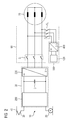
- FIG. 1 one recognizes a rail vehicle 10, of which the sake of clarity in the FIG. 1 only a wheel 20 and an electric current collector 30 are shown for connection to a contact wire 40, not shown.
- a drive circuit 50 which is connected via a switching device 60 with a drive motor in the form of a permanent-magnet machine 70, for example a permanent magnet synchronous machine, transverse flux machine or transversal flux reluctance machine.
- the drive circuit 50 and the switching device 60 form a feed branch for the machine 70, which is used during normal driving operation for operating the rail vehicle 10.
- FIG. 1 In addition, one recognizes an emergency or towing 100, which is also connected to the switching device 60 and thus to the machine 70.
- the emergency or towing branch 100 has an inverter unit 110 and a consuming device 120 connected thereto. Consumption device 120 is therefore not directly connected to machine 70, but only indirectly.
- the vehicle 10 according to FIG. 1 can be operated, for example, as follows:
- the drive circuit 50 is equipped with an input circuit 200, an intermediate circuit capacitor C and an inverter 220.
- a first switching unit S1 of the switching device 60 is closed, so that the machine 70 is electrically connected to the inverter 220 of the drive circuit 50. Since the emergency or towing branch 100 is not required in normal operation, a second switching unit S2 of the switching device 60 is opened, so that neither the converter unit 110 nor the consuming device 120 are connected to the machine 70.
- the switching device 60 is switched by the first switching unit S1, which is formed for example by a mechanical switch or an electronic switch is turned off. As a result, the engine 70 is electrically disconnected from the inverter 220 of the drive circuit 50.
- the second switching unit S2 which is also formed for example by a mechanical switch or an electronic switch, the switching device 60 is turned on, so that the inverter unit 110 and the consuming device 120 are connected to the machine 70 , The machine 70 will generate electrical voltage during towing, which is fed via the converter unit 110 in the consuming device 120.
- the energy generated by the machine 70 may be used by the consuming device 120 to cool the machine 70.
- the consumption device 120 is formed for this purpose, for example, by a fan, fan or a circulation pump or other cooling system. Cooling the machine 70 during towing ensures that it does not overheat the machine 70 can come. Namely, such overheating would occur, for example, when the rail vehicle is towed at too high a speed and the eddy current losses generated in the stator of the machine 70 lead to an unduly high heating of the machine.
- the consumption device 120 is thus preferably used to avoid a towing speed limitation in towing operation, which would otherwise have to be maintained in the case without cooling.
- a lighting device or an air conditioning system of the rail vehicle can be fed by the machine 70.
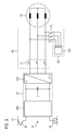
- FIG. 2 a second embodiment of a vehicle 10 is shown.
- the consumption device 120 is connected via a rectifier 400 to the second switching unit S2 of the switching device 60; an inverter unit as in the first embodiment according to FIG. 1 is therefore not available.
- the second embodiment corresponds to FIG. 2 according to the first embodiment FIG. 1 ,
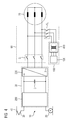
- FIG. 3 a third embodiment of a vehicle is shown.
- the consumption device 120 is electrically connected directly to the second switching unit S2 of the switching device 50 and is thus applied or operated in the event of a towing of the rail vehicle by the machine 70 directly with AC.
- FIG. 4 a fourth embodiment of a vehicle is shown.
- the consuming device 120 is connected via a transformer 410 to the second switching unit S2 of the switching device 60.
- the fourth embodiment corresponds to the other embodiments according to the FIGS. 1 to 3 ,
Landscapes
- Engineering & Computer Science (AREA)
- Power Engineering (AREA)
- Transportation (AREA)
- Mechanical Engineering (AREA)
- Electric Propulsion And Braking For Vehicles (AREA)
Applications Claiming Priority (1)
| Application Number | Priority Date | Filing Date | Title |
|---|---|---|---|
| DE200710034395 DE102007034395A1 (de) | 2007-07-24 | 2007-07-24 | Fahrzeug und Verfahren zu dessen Betrieb |
Publications (1)
| Publication Number | Publication Date |
|---|---|
| EP2018993A2 true EP2018993A2 (fr) | 2009-01-28 |
Family
ID=40032379
Family Applications (1)
| Application Number | Title | Priority Date | Filing Date |
|---|---|---|---|
| EP20080104830 Withdrawn EP2018993A2 (fr) | 2007-07-24 | 2008-07-22 | Véhicule et son procédé de fonctionnement |
Country Status (2)
| Country | Link |
|---|---|
| EP (1) | EP2018993A2 (fr) |
| DE (1) | DE102007034395A1 (fr) |
Families Citing this family (1)
| Publication number | Priority date | Publication date | Assignee | Title |
|---|---|---|---|---|
| DE102024211379B3 (de) * | 2024-11-28 | 2026-01-15 | Siemens Mobility GmbH | Verfahren und Einrichtung zum Betreiben eines Fahrzeugs während eines Bergungsbetriebs |
Family Cites Families (1)
| Publication number | Priority date | Publication date | Assignee | Title |
|---|---|---|---|---|
| DE102004003533A1 (de) * | 2004-01-23 | 2005-08-18 | Siemens Ag | Kühlsystem |
-
2007
- 2007-07-24 DE DE200710034395 patent/DE102007034395A1/de not_active Withdrawn
-
2008
- 2008-07-22 EP EP20080104830 patent/EP2018993A2/fr not_active Withdrawn
Also Published As
| Publication number | Publication date |
|---|---|
| DE102007034395A1 (de) | 2009-01-29 |
Similar Documents
| Publication | Publication Date | Title |
|---|---|---|
| DE102012205109B4 (de) | Verfahren zum Betreiben einer Energiespeichereinrichtung, Energiespeichereinrichtung zum Erzeugen einer Versorgungsspannung für eine elektrische Maschine sowie Sytem mit einer Energiespeichereinrichtung | |
| DE102008023332B4 (de) | Dieselelektrisches Antriebssystem | |
| EP2941363B2 (fr) | Alimentation en énergie électrique de moteurs électriques de propulsion d'un véhicule ferroviaire à l'aide d'une pluralité de moteurs à combustion | |
| DE102006010537A1 (de) | Dieselelektrisches Antriebssystem mit einem permanent erregten Synchrongenerator | |
| DE102016103041A1 (de) | Leistungsumwandlungsvorrichtung | |
| DE102009046617A1 (de) | Wechselrichter | |
| DE102022121516A1 (de) | Erregerschaltung für eine fremderregte Synchronmaschine, Kraftfahrzeug und Verfahren zur Entregung einer Erregerwicklung | |
| DE102022123264A1 (de) | Erregerschaltung für eine fremderregte Synchronmaschine, Kraftfahrzeug und Verfahren zur Entregung einer Erregerwicklung | |
| DE102021003587A1 (de) | Verfahren zum Betrieb eines batterieelektrischen Fahrzeugs | |
| DE10234594A1 (de) | Generator/Motor-System und Verfahren zum Betreiben dieses Generator/Motor-Systems | |
| EP2220738B1 (fr) | Système d'entraînement et procédé de commande correspondant | |
| EP2018993A2 (fr) | Véhicule et son procédé de fonctionnement | |
| DE102021003621A1 (de) | Verfahren zum Betrieb eines batterieelektrischen Fahrzeugs | |
| EP3893386B1 (fr) | Appareil de commande, circuit de commande et véhicule automobile | |
| DE102021102334A1 (de) | Überspannungsschutz für eine fremderregte Synchronmaschine | |
| DE102023117057A1 (de) | Stromrichter, elektrische Maschineneinheit und Verfahren zum Stromrichten | |
| WO2013092043A2 (fr) | Circuit convertisseur de courant | |
| DE112011103684T5 (de) | Elektrische Maschine mit einem integrierten Wechselrichter | |
| DE112011103683T5 (de) | Elektrisches Maschinensystem umfassend eine elektrische Wechselstrommaschine mit einem Schaltmodul | |
| DE102021103023A1 (de) | Invertereinrichtung und elektrische Antriebsanordnung | |
| DE102020201409A1 (de) | Elektromotor-Inverter und Fahrzeugbordnetz mit Traktionsantrieb | |
| DE102020126340A1 (de) | Wechselrichter für eine Antriebseinrichtung eines elektrisch antreibbaren Kraftfahrzeugs | |
| DE102014209868A1 (de) | Steuerverfahren und Schaltungsanordnung zum Betrieb einer Antriebsmaschine | |
| DE102023133323B4 (de) | Wechselrichterschaltung und elektromotorisches Antriebssystem | |
| DE102020207856A1 (de) | Inverter für eine elektrische Maschine, elektrische Maschine mit solch einem Inverter sowie Lenksystem mit solch einer elektrischen Maschine |
Legal Events
| Date | Code | Title | Description |
|---|---|---|---|
| PUAI | Public reference made under article 153(3) epc to a published international application that has entered the european phase |
Free format text: ORIGINAL CODE: 0009012 |
|
| AK | Designated contracting states |
Kind code of ref document: A2 Designated state(s): AT BE BG CH CY CZ DE DK EE ES FI FR GB GR HR HU IE IS IT LI LT LU LV MC MT NL NO PL PT RO SE SI SK TR |
|
| AX | Request for extension of the european patent |
Extension state: AL BA MK RS |
|
| RAP1 | Party data changed (applicant data changed or rights of an application transferred) |
Owner name: SIEMENS AKTIENGESELLSCHAFT |
|
| STAA | Information on the status of an ep patent application or granted ep patent |
Free format text: STATUS: THE APPLICATION IS DEEMED TO BE WITHDRAWN |
|
| 18D | Application deemed to be withdrawn |
Effective date: 20160202 |