EP2941363B2 - Alimentation en énergie électrique de moteurs électriques de propulsion d'un véhicule ferroviaire à l'aide d'une pluralité de moteurs à combustion - Google Patents
Alimentation en énergie électrique de moteurs électriques de propulsion d'un véhicule ferroviaire à l'aide d'une pluralité de moteurs à combustion Download PDFInfo
- Publication number
- EP2941363B2 EP2941363B2 EP14700139.0A EP14700139A EP2941363B2 EP 2941363 B2 EP2941363 B2 EP 2941363B2 EP 14700139 A EP14700139 A EP 14700139A EP 2941363 B2 EP2941363 B2 EP 2941363B2
- Authority
- EP
- European Patent Office
- Prior art keywords
- electrical
- machine
- internal combustion
- rectifier
- power converter
- Prior art date
- Legal status (The legal status is an assumption and is not a legal conclusion. Google has not performed a legal analysis and makes no representation as to the accuracy of the status listed.)
- Active
Links
- 238000002485 combustion reaction Methods 0.000 title claims description 97
- 238000000034 method Methods 0.000 claims description 25
- 238000004146 energy storage Methods 0.000 description 24
- 239000000446 fuel Substances 0.000 description 6
- 230000003137 locomotive effect Effects 0.000 description 5
- 239000003990 capacitor Substances 0.000 description 2
- 238000012983 electrochemical energy storage Methods 0.000 description 2
- 238000009499 grossing Methods 0.000 description 2
- 238000012986 modification Methods 0.000 description 2
- 230000004048 modification Effects 0.000 description 2
- 230000001133 acceleration Effects 0.000 description 1
- 230000003213 activating effect Effects 0.000 description 1
- 238000004378 air conditioning Methods 0.000 description 1
- 230000000903 blocking effect Effects 0.000 description 1
- 238000010276 construction Methods 0.000 description 1
- 238000001816 cooling Methods 0.000 description 1
- 238000005516 engineering process Methods 0.000 description 1
- 238000010438 heat treatment Methods 0.000 description 1
- 238000009434 installation Methods 0.000 description 1
- 238000004519 manufacturing process Methods 0.000 description 1
- 230000001172 regenerating effect Effects 0.000 description 1
- 230000001360 synchronised effect Effects 0.000 description 1
Images

Classifications
-
- B—PERFORMING OPERATIONS; TRANSPORTING
- B60—VEHICLES IN GENERAL
- B60L—PROPULSION OF ELECTRICALLY-PROPELLED VEHICLES; SUPPLYING ELECTRIC POWER FOR AUXILIARY EQUIPMENT OF ELECTRICALLY-PROPELLED VEHICLES; ELECTRODYNAMIC BRAKE SYSTEMS FOR VEHICLES IN GENERAL; MAGNETIC SUSPENSION OR LEVITATION FOR VEHICLES; MONITORING OPERATING VARIABLES OF ELECTRICALLY-PROPELLED VEHICLES; ELECTRIC SAFETY DEVICES FOR ELECTRICALLY-PROPELLED VEHICLES
- B60L3/00—Electric devices on electrically-propelled vehicles for safety purposes; Monitoring operating variables, e.g. speed, deceleration or energy consumption
- B60L3/0092—Electric devices on electrically-propelled vehicles for safety purposes; Monitoring operating variables, e.g. speed, deceleration or energy consumption with use of redundant elements for safety purposes
-
- B—PERFORMING OPERATIONS; TRANSPORTING
- B60—VEHICLES IN GENERAL
- B60L—PROPULSION OF ELECTRICALLY-PROPELLED VEHICLES; SUPPLYING ELECTRIC POWER FOR AUXILIARY EQUIPMENT OF ELECTRICALLY-PROPELLED VEHICLES; ELECTRODYNAMIC BRAKE SYSTEMS FOR VEHICLES IN GENERAL; MAGNETIC SUSPENSION OR LEVITATION FOR VEHICLES; MONITORING OPERATING VARIABLES OF ELECTRICALLY-PROPELLED VEHICLES; ELECTRIC SAFETY DEVICES FOR ELECTRICALLY-PROPELLED VEHICLES
- B60L50/00—Electric propulsion with power supplied within the vehicle
- B60L50/10—Electric propulsion with power supplied within the vehicle using propulsion power supplied by engine-driven generators, e.g. generators driven by combustion engines
- B60L50/13—Electric propulsion with power supplied within the vehicle using propulsion power supplied by engine-driven generators, e.g. generators driven by combustion engines using AC generators and AC motors
-
- B—PERFORMING OPERATIONS; TRANSPORTING
- B60—VEHICLES IN GENERAL
- B60L—PROPULSION OF ELECTRICALLY-PROPELLED VEHICLES; SUPPLYING ELECTRIC POWER FOR AUXILIARY EQUIPMENT OF ELECTRICALLY-PROPELLED VEHICLES; ELECTRODYNAMIC BRAKE SYSTEMS FOR VEHICLES IN GENERAL; MAGNETIC SUSPENSION OR LEVITATION FOR VEHICLES; MONITORING OPERATING VARIABLES OF ELECTRICALLY-PROPELLED VEHICLES; ELECTRIC SAFETY DEVICES FOR ELECTRICALLY-PROPELLED VEHICLES
- B60L15/00—Methods, circuits, or devices for controlling the traction-motor speed of electrically-propelled vehicles
- B60L15/007—Physical arrangements or structures of drive train converters specially adapted for the propulsion motors of electric vehicles
-
- B—PERFORMING OPERATIONS; TRANSPORTING
- B60—VEHICLES IN GENERAL
- B60K—ARRANGEMENT OR MOUNTING OF PROPULSION UNITS OR OF TRANSMISSIONS IN VEHICLES; ARRANGEMENT OR MOUNTING OF PLURAL DIVERSE PRIME-MOVERS IN VEHICLES; AUXILIARY DRIVES FOR VEHICLES; INSTRUMENTATION OR DASHBOARDS FOR VEHICLES; ARRANGEMENTS IN CONNECTION WITH COOLING, AIR INTAKE, GAS EXHAUST OR FUEL SUPPLY OF PROPULSION UNITS IN VEHICLES
- B60K5/00—Arrangement or mounting of internal-combustion or jet-propulsion units
- B60K5/08—Arrangement or mounting of internal-combustion or jet-propulsion units comprising more than one engine
-
- B—PERFORMING OPERATIONS; TRANSPORTING
- B60—VEHICLES IN GENERAL
- B60L—PROPULSION OF ELECTRICALLY-PROPELLED VEHICLES; SUPPLYING ELECTRIC POWER FOR AUXILIARY EQUIPMENT OF ELECTRICALLY-PROPELLED VEHICLES; ELECTRODYNAMIC BRAKE SYSTEMS FOR VEHICLES IN GENERAL; MAGNETIC SUSPENSION OR LEVITATION FOR VEHICLES; MONITORING OPERATING VARIABLES OF ELECTRICALLY-PROPELLED VEHICLES; ELECTRIC SAFETY DEVICES FOR ELECTRICALLY-PROPELLED VEHICLES
- B60L2200/00—Type of vehicles
- B60L2200/26—Rail vehicles
-
- B—PERFORMING OPERATIONS; TRANSPORTING
- B60—VEHICLES IN GENERAL
- B60L—PROPULSION OF ELECTRICALLY-PROPELLED VEHICLES; SUPPLYING ELECTRIC POWER FOR AUXILIARY EQUIPMENT OF ELECTRICALLY-PROPELLED VEHICLES; ELECTRODYNAMIC BRAKE SYSTEMS FOR VEHICLES IN GENERAL; MAGNETIC SUSPENSION OR LEVITATION FOR VEHICLES; MONITORING OPERATING VARIABLES OF ELECTRICALLY-PROPELLED VEHICLES; ELECTRIC SAFETY DEVICES FOR ELECTRICALLY-PROPELLED VEHICLES
- B60L2210/00—Converter types
- B60L2210/30—AC to DC converters
-
- B—PERFORMING OPERATIONS; TRANSPORTING
- B60—VEHICLES IN GENERAL
- B60L—PROPULSION OF ELECTRICALLY-PROPELLED VEHICLES; SUPPLYING ELECTRIC POWER FOR AUXILIARY EQUIPMENT OF ELECTRICALLY-PROPELLED VEHICLES; ELECTRODYNAMIC BRAKE SYSTEMS FOR VEHICLES IN GENERAL; MAGNETIC SUSPENSION OR LEVITATION FOR VEHICLES; MONITORING OPERATING VARIABLES OF ELECTRICALLY-PROPELLED VEHICLES; ELECTRIC SAFETY DEVICES FOR ELECTRICALLY-PROPELLED VEHICLES
- B60L2210/00—Converter types
- B60L2210/40—DC to AC converters
-
- B—PERFORMING OPERATIONS; TRANSPORTING
- B60—VEHICLES IN GENERAL
- B60L—PROPULSION OF ELECTRICALLY-PROPELLED VEHICLES; SUPPLYING ELECTRIC POWER FOR AUXILIARY EQUIPMENT OF ELECTRICALLY-PROPELLED VEHICLES; ELECTRODYNAMIC BRAKE SYSTEMS FOR VEHICLES IN GENERAL; MAGNETIC SUSPENSION OR LEVITATION FOR VEHICLES; MONITORING OPERATING VARIABLES OF ELECTRICALLY-PROPELLED VEHICLES; ELECTRIC SAFETY DEVICES FOR ELECTRICALLY-PROPELLED VEHICLES
- B60L2220/00—Electrical machine types; Structures or applications thereof
- B60L2220/40—Electrical machine applications
- B60L2220/42—Electrical machine applications with use of more than one motor
-
- H—ELECTRICITY
- H02—GENERATION; CONVERSION OR DISTRIBUTION OF ELECTRIC POWER
- H02J—CIRCUIT ARRANGEMENTS OR SYSTEMS FOR SUPPLYING OR DISTRIBUTING ELECTRIC POWER; SYSTEMS FOR STORING ELECTRIC ENERGY
- H02J1/00—Circuit arrangements for dc mains or dc distribution networks
- H02J1/10—Parallel operation of dc sources
- H02J1/108—Parallel operation of dc sources using diodes blocking reverse current flow
-
- H—ELECTRICITY
- H02—GENERATION; CONVERSION OR DISTRIBUTION OF ELECTRIC POWER
- H02M—APPARATUS FOR CONVERSION BETWEEN AC AND AC, BETWEEN AC AND DC, OR BETWEEN DC AND DC, AND FOR USE WITH MAINS OR SIMILAR POWER SUPPLY SYSTEMS; CONVERSION OF DC OR AC INPUT POWER INTO SURGE OUTPUT POWER; CONTROL OR REGULATION THEREOF
- H02M1/00—Details of apparatus for conversion
- H02M1/0067—Converter structures employing plural converter units, other than for parallel operation of the units on a single load
- H02M1/008—Plural converter units for generating at two or more independent and non-parallel outputs, e.g. systems with plural point of load switching regulators
-
- Y—GENERAL TAGGING OF NEW TECHNOLOGICAL DEVELOPMENTS; GENERAL TAGGING OF CROSS-SECTIONAL TECHNOLOGIES SPANNING OVER SEVERAL SECTIONS OF THE IPC; TECHNICAL SUBJECTS COVERED BY FORMER USPC CROSS-REFERENCE ART COLLECTIONS [XRACs] AND DIGESTS
- Y02—TECHNOLOGIES OR APPLICATIONS FOR MITIGATION OR ADAPTATION AGAINST CLIMATE CHANGE
- Y02T—CLIMATE CHANGE MITIGATION TECHNOLOGIES RELATED TO TRANSPORTATION
- Y02T10/00—Road transport of goods or passengers
- Y02T10/60—Other road transportation technologies with climate change mitigation effect
- Y02T10/64—Electric machine technologies in electromobility
-
- Y—GENERAL TAGGING OF NEW TECHNOLOGICAL DEVELOPMENTS; GENERAL TAGGING OF CROSS-SECTIONAL TECHNOLOGIES SPANNING OVER SEVERAL SECTIONS OF THE IPC; TECHNICAL SUBJECTS COVERED BY FORMER USPC CROSS-REFERENCE ART COLLECTIONS [XRACs] AND DIGESTS
- Y02—TECHNOLOGIES OR APPLICATIONS FOR MITIGATION OR ADAPTATION AGAINST CLIMATE CHANGE
- Y02T—CLIMATE CHANGE MITIGATION TECHNOLOGIES RELATED TO TRANSPORTATION
- Y02T10/00—Road transport of goods or passengers
- Y02T10/60—Other road transportation technologies with climate change mitigation effect
- Y02T10/70—Energy storage systems for electromobility, e.g. batteries
-
- Y—GENERAL TAGGING OF NEW TECHNOLOGICAL DEVELOPMENTS; GENERAL TAGGING OF CROSS-SECTIONAL TECHNOLOGIES SPANNING OVER SEVERAL SECTIONS OF THE IPC; TECHNICAL SUBJECTS COVERED BY FORMER USPC CROSS-REFERENCE ART COLLECTIONS [XRACs] AND DIGESTS
- Y02—TECHNOLOGIES OR APPLICATIONS FOR MITIGATION OR ADAPTATION AGAINST CLIMATE CHANGE
- Y02T—CLIMATE CHANGE MITIGATION TECHNOLOGIES RELATED TO TRANSPORTATION
- Y02T10/00—Road transport of goods or passengers
- Y02T10/60—Other road transportation technologies with climate change mitigation effect
- Y02T10/7072—Electromobility specific charging systems or methods for batteries, ultracapacitors, supercapacitors or double-layer capacitors
-
- Y—GENERAL TAGGING OF NEW TECHNOLOGICAL DEVELOPMENTS; GENERAL TAGGING OF CROSS-SECTIONAL TECHNOLOGIES SPANNING OVER SEVERAL SECTIONS OF THE IPC; TECHNICAL SUBJECTS COVERED BY FORMER USPC CROSS-REFERENCE ART COLLECTIONS [XRACs] AND DIGESTS
- Y02—TECHNOLOGIES OR APPLICATIONS FOR MITIGATION OR ADAPTATION AGAINST CLIMATE CHANGE
- Y02T—CLIMATE CHANGE MITIGATION TECHNOLOGIES RELATED TO TRANSPORTATION
- Y02T10/00—Road transport of goods or passengers
- Y02T10/60—Other road transportation technologies with climate change mitigation effect
- Y02T10/72—Electric energy management in electromobility
Definitions
- the invention relates to an arrangement for supplying electric traction motors in a rail vehicle with electrical energy, the arrangement having at least two internal combustion engines.
- An associated electrical machine for generating the electrical energy is provided for each of the at least two internal combustion engines, wherein the electrical machine is mechanically coupled to the internal combustion engine so that it is driven by the internal combustion engine when the electrical machine is operating as a generator.
- At least a first and a second internal combustion engine-machine combination are thus formed.
- the at least one electric traction motor of the rail vehicle can be electrically connected to at least one of the electric machines via at least one traction connection.
- the invention further relates to a method for supplying electric traction motors in a rail vehicle with electrical energy, wherein at least two internal combustion engines are each operated in combination with an associated electric machine, so that at least a first and a second internal combustion engine-machine combination are operated.
- a first operating state of the machine at least a first of the electric machines generates alternating current driven by the associated internal combustion engine during generator operation of the respective electric machine, which is used to operate at least one electric traction motor.
- a second one of the electrical machines is supplied with alternating current from a second machine power converter assigned to it and drives the internal combustion engine assigned to it.
- the rail vehicle is, for example, a locomotive.
- the invention is not limited to this. Rather, the rail vehicle can also be a train set, for example.
- the electrical energy generated by the internal combustion engines is available in the rail vehicle not only to supply the at least one traction motor, but also to supply other electrical consumers.
- the other consumers are in particular so-called auxiliary operations, which do not directly generate traction, but may be absolutely necessary for the running of the rail vehicle.
- Auxiliary operations can generally be defined by the fact that they are supplied with electrical energy from the usually existing DC intermediate circuit via their own auxiliary operation inverter or a plurality of their own auxiliary operation inverters.
- the auxiliary operations include, for example, fans and other cooling devices that cool the combustion engines, the traction motors and/or other devices required for driving (e.g. power converters).
- a braking system is required for driving and components of the braking system such as air compressors are therefore auxiliary operations.
- auxiliary operations are a fire extinguishing device of the rail vehicle, electronic devices for controlling the operation of the rail vehicle, battery chargers, heaters required at least temporarily for driving operation, e.g. window heating of the windshield, and / or lighting device in the driver's compartment.
- auxiliary operations can be distinguished from electrical devices that are only available for the comfort of passengers, such as lights in vehicle compartments. Such electrical devices are usually supplied with electrical energy in trains via the so-called train busbar.
- the train busbar is not connected to the DC link via the auxiliary power inverter or one of the auxiliary power inverters, but rather via its own inverter.
- the electrical energy generated by the electrical machines can also be fed into a DC intermediate circuit in the present invention via at least one rectifier (hereinafter: generator rectifier, since alternating current generated by the generator is rectified).
- generator rectifier since alternating current generated by the generator is rectified.
- inverters are connected to the DC intermediate circuit, which in turn generate the alternating current at the desired electrical voltage level or in the desired electrical voltage range that is required for the consumers and systems connected on the alternating voltage side.
- DC-voltage converters can be provided on their DC voltage side and/or transformers on their AC voltage side in order to change the voltage level.
- Other electrical converters can also be connected to the DC link either directly or indirectly.
- auxiliary operations in addition to the auxiliary operations mentioned, other electrical consumers, such as electrical devices such as lighting, air conditioning and information systems that are available for the comfort of passengers, can also be supplied with electrical energy from the DC intermediate circuit, e.g. B. via a different inverter than the auxiliary operations required for driving.
- a plurality of traction motors of the rail vehicle via one or more traction inverters; a train current busbar via an additional converter or directly; Auxiliary operations required for driving via an auxiliary operations inverter.
- further converters can be connected to the intermediate circuit, for example for the purpose of converting unnecessary energy that occurs when Braking of the rail vehicle is fed into the intermediate circuit, in heat.
- An example of such an arrangement is in WO 2009/077184 A1 described.
- a plurality of combustion engine-machine combinations therefore enables part-load operation of the rail vehicle, i.e. operation in which the maximum possible electrical power is not required.
- Part-load operation is therefore understood to mean an operation in which the mechanical power of only part of the internal combustion engines is sufficient to provide the required electrical power.
- part-load operation also has the advantage that the noise pollution in the environment is lower.
- there may be four internal combustion engine-machine combinations with each combination preferably being able to be operated either at idle or at the optimal power point, independently of the other combinations.
- more than two operating modes can be set for each combination, e.g. in addition to the two operating modes mentioned, operation with medium power of the electrical machine operated as a generator.
- Electrical auxiliary operations which are present in addition to the electric traction motors and are supplied with electrical energy from the DC intermediate circuit, include in particular those auxiliary operations which, as mentioned above, are required for the driving operation of the rail vehicle. If the auxiliary power inverter, via which these auxiliary power are electrically connected to the DC link, fails or has to be switched off, driving cannot continue. This applies even though the DC intermediate circuit and the supply of the traction motors from the intermediate circuit may still be functional.
- One, more or all of the engine-engine combinations could be shut down, so that in due course it becomes necessary to start one or more shut-down engine-engine combinations.
- the combustion engine of the combination must be started, which requires appropriate energy.
- at least one internal combustion engine is started with the help of the associated electrical machine, in that the electrical machine drives the internal combustion engine that is mechanically coupled to it.
- the fuel supply to the internal combustion engine can be started, so that the internal combustion engine begins to work under its own power.
- the internal combustion engine has started, although the starting process can continue until the internal combustion engine reaches a speed at which it can be operated permanently without load without stopping and is ready at any time to increase its speed and also work under load.
- This speed is commonly referred to as an idle speed.
- the internal combustion engine drives the electric machine, which, however, does not supply energy to an electrical load or to a small extent. If the speed is increased further, the internal combustion engine increases the power with which the electric machine generates alternating current, so that electrical consumers can be supplied with electrical energy from the electric machine.
- the energy for starting at least one of the internal combustion engines is expediently obtained from an energy storage device of the rail vehicle, in particular an electrical or electrochemical energy storage device, in particular the vehicle battery.
- an energy storage device of the rail vehicle in particular an electrical or electrochemical energy storage device, in particular the vehicle battery.
- the start of several internal combustion engines and the frequent repetition of starting processes after switching off the internal combustion engines places considerable strain on the vehicle's energy storage system.
- the storage capacity of the energy storage can be increased. However, this is associated with additional costs and/or an increase in the weight and construction volume of the energy storage device, whereby the energy storage device can also consist of units distributed throughout the vehicle.
- a machine inverter which is supplied with direct current from the energy storage or the voltage converter in order to supply the electrical machine with alternating current, is designed for a direct voltage of the order of 750 V or 1 kV.
- US 2011/0080040 A1 describes a drive device with diesel engines, each of which supplies rotational energy to a generator in order to generate an alternating current which is supplied to a corresponding rectifier.
- Each rectifier is electrically connected to one of the generators to produce a direct current that is supplied to a DC link.
- Inverters connected to the DC link convert the DC signal on the DC link into alternating current to drive a drive motor.
- a control is connected to the generators.
- WO 2006/020587 A2 describes methods for regenerative braking of a hybrid locomotive.
- the locomotive can have several engines.
- an internal combustion engine-machine combination that has already started or is in operation is used to start at least one further internal combustion engine-machine combination.
- alternating current which is generated by the electrical machine of the first, already operated combination, i.e. is passed from the first electrical machine to the second electrical machine of the not yet started combination in order to operate the second electrical machine and thereby the internal combustion engine of the second to start the combination.
- the same procedure can be followed if a need for the second electrical machine to be supplied with electrical energy arises or exists during the further course of the starting process or during other operation of the second combination.
- This can be the case in particular if the internal combustion engine is to be operated at idle (i.e. at idle speed) with reduced fuel supply or switched off fuel supply.
- this can also be the case if the operation of the second internal combustion engine is disrupted and the second electrical machine therefore drives the second internal combustion engine, for example in order to avoid an undesirable standstill of the second internal combustion engine.
- a machine power converter is assigned to both the first and second electrical machines, the alternating current side of which is electrically connected to the associated electrical machine.
- the machine power converters each have a DC side, with the DC sides of the machine power converters being electrically connected to one another via a DC voltage connection (i.e. line).
- the DC sides of the machine power converters are therefore directly connected to one another, without additional power converters (e.g. voltage converters).
- At least one of the machine power converters and preferably all machine power converters, the DC sides of which are directly connected to one another via the DC voltage line, are connected to an electrical capacitance (e.g. a capacitor or an arrangement of capacitors).
- an electrical capacitance e.g. a capacitor or an arrangement of capacitors.
- One connection of the capacity is connected to the first potential of the DC voltage connection of the machine power converter and the second, opposite connection of the capacity is connected to the second potential of the DC voltage connection of the machine power converter.
- each of the DC voltage sides of the machine power converters is coupled to a capacitance in this way.
- This has the advantage that fluctuations in the direct voltage are compensated for. But even a single capacitance, whose poles are connected to the two potentials of the DC voltage line, leads to a smoothing of DC voltage fluctuations.
- a capacity or the majority of such capacities has the advantage that electrical energy is stored therein as soon as the capacity is charged.
- this has the advantage that a higher power is briefly available for starting or operating at least one of the internal combustion engine-machine combinations.
- the capacity or the plurality of capacities can be charged before, during and/or after the start of the first internal combustion engine-machine combinations and only then can the second internal combustion engine-machine combinations be started.
- the invention has the advantage that the vehicle's energy storage is placed under less strain because it is only needed to start the first combination. In addition, the reliability of the rail vehicle is increased, although a redundant voltage converter for converting the voltage level at the output of the energy storage is not absolutely necessary.
- the electrical machines of the combinations feed electrical energy into a DC intermediate circuit of the vehicle via at least one rectifier.
- the additional machine power converters which are connected to each other via the DC voltage connection, save overall weight and volume.
- the reason for this is that the at least one rectifier between the electrical machines and the DC link is designed for very high power and therefore requires a correspondingly large weight and volume. If the rectifier is also to be operated as an inverter, the weight and volume will increase.
- the additional machine power converters are designed for relatively small electrical powers, particularly in the case of at least one additional electrical capacity. The additional effort for the machine power converters is therefore low.
- At least one electrical switch is provided and optionally several electrical switches are provided, which are controlled, opened and opened by a control arrangement can be closed.
- This makes it possible to electrically isolate at least one of the machine power converters from the other machine power converters (in this case, at least one electrical switch is provided in the DC voltage connection or is provided at the connection of the machine power converter to the DC voltage connection) and/or to disconnect at least one of the machine power converters from the electrical machine assigned to it (in this case the additional electrical switch is arranged in the connection between the AC voltage side of the machine power converter and the electrical machine).
- An electrical switch is provided with which the at least one rectifier or one of the rectifiers (also called generator rectifier) can be separated from the associated electrical machine or machines and/or the DC intermediate circuit.
- an electrical machine is electrically isolated from the DC intermediate circuit while it supplies energy (in particular for starting an internal combustion engine of a different combination) via the DC voltage connection to an electrical machine of a different combination.
- a first of the electrical machines is electrically isolated from the DC intermediate circuit, while it supplies a second of the electrical machines with electrical energy via the DC voltage line.
- the control arrangement is designed such that the first electrical machine is electrically isolated from the DC intermediate circuit by means of an electrical switch, while it supplies the second electrical machine with electrical energy via the DC line.
- at least one electrical machine is supplied via the DC voltage connection without using the DC intermediate circuit.
- the following also refers to a traction connection, via which a traction motor of the rail vehicle is supplied.
- the electric machine supplies energy (in particular for starting an internal combustion engine of a different combination) via the DC connection to an electric machine of a different combination
- it does not supply any traction motor with electrical energy.
- an electrical switch that is open is provided either between the electric machine and the traction connection or between the traction connection and the traction motor.
- a diode is usually referred to as a freewheeling diode.
- the electrical one-way valves are preferably designed so that they can carry the electrical current required to supply other internal combustion engine-machine combinations.
- a method for supplying electric traction motors in a rail vehicle with electrical energy is proposed, which has the features of claim 3.
- Both the previously defined arrangement and the previously defined method allow, in the presence of more than one internal combustion engine-machine combination, not only the supply of one of the machine converters with direct current that has been rectified from alternating current from the electrical machine of another combination. Rather, a majority of the machine converters can also be supplied with direct current, which is rectified at least from alternating current from the electrical machine of another of the combinations. Furthermore, it is also possible to supply one or more machine power converters of one or more other combinations with rectified alternating current from a plurality of electrical machines.
- the DC voltage line (preferably electrically disconnectable via at least one electrical switch) is connected to an electrical connection via which an electrical or electrochemical energy storage device (in particular the vehicle battery) of the vehicle can feed electrical energy into the DC voltage line during operation of the vehicle.
- an electrical or electrochemical energy storage device in particular the vehicle battery
- the DC voltage line can therefore be used in particular to start at least one of the internal combustion engines.
- the energy storage device feeds electrical energy into the DC voltage line and this electrical energy can be used to start the internal combustion engine by the machine converter generating alternating current and using it to operate the electrical machine of the combination.
- the electrical energy from the vehicle's energy storage can be used to charge an electrical capacity whose poles are connected between the potentials of the DC voltage line.
- first operating state refers to the electrical machine of a specific combination or to the combination. This also applies to the term “second operating state”. Other operating states can occur, for example the combustion engine is at a standstill. In the first operating state, the electric machine is driven by the associated internal combustion engine and generates an alternating electrical voltage, due to which an alternating current can flow. In the second operating state, the electric machine drives the associated internal combustion engine while being supplied with alternating current from the associated machine power converter (also called machine inverter). This means that in the case of several internal combustion engine-machine combinations, the different electrical machines or combinations can be in different operating states at the same time.
- machine power converter also called machine inverter
- the machine of the second combination While, for example, the electric machine of the first combination is in the first operating state, the machine of the second combination, for example, is in the second operating state. However, it cannot be ruled out that all electrical machines can be in the same operating state at a certain point in time. If this is the second operating state, energy for operating the electrical machines can be supplied to consumers, in particular via a DC intermediate circuit of the arrangement. This also applies if none or not all of the electrical machines are in the second operating state.
- the energy from the DC intermediate circuit for supplying the electrical machine(s) can, for example, be generated as AC energy by the at least one traction motor during a braking process of the rail vehicle and fed into the DC intermediate circuit via the associated traction inverter.
- the traction connection can in particular be an AC voltage connection on the AC voltage side of a traction inverter or the DC voltage connection of the traction inverter.
- the electrical machines can supply the alternating current they generate to at least one rectifier (generator-rectifier) and the current rectified by the rectifier can be fed into a DC intermediate circuit.
- At least one traction inverter is connected to this DC intermediate circuit in a manner known per se.
- At least one of the machine power converters also forms the generator rectifier.
- this is not in accordance with the patent claims and is not preferred, in particular for the reasons already mentioned above.
- the arrangement therefore has, in addition to the machine power converters, at least one generator rectifier for rectifying alternating currents that are generated by the electrical machines during generator operation of the respective electrical machine, with the at least one generator rectifier on its AC voltage side having at least one of the electric machines is connected and is connected on its DC voltage side to a DC intermediate circuit, via which the electric traction motor can be supplied with electrical energy.
- this corresponds to rectifying, in the first operating state of the electrical machine or the electrical machines, the alternating current generated by at least one generator rectifier, which is present in addition to the machine power converters, and feeding it into a DC intermediate circuit from which the at least one electrical Traction motor is supplied with electrical energy.
- a generator rectifier is connected to the first electrical machine on its AC voltage side and is connected to the DC intermediate circuit on its DC voltage side.
- At least one electrical capacitance which is connected between the electrical potentials of the DC link, can first be charged with electrical energy, and only then can the alternating current generated be fed into the DC link by the at least one generator rectifier.
- the rectifier via which the electrical machine is connected to the DC intermediate circuit, does not feed any direct current into the DC intermediate circuit at the beginning of the starting process. The reason for this is that at the beginning of the starting process, the machine power converter should deliver a high alternating voltage to operate the electrical machine. This would in turn lead to high currents in the DC link and also reduce the power of the machine converter that is available for the starting process.
- control arrangement can have a plurality of control units which are designed to control the power converters and optionally other devices of the supply arrangement.
- control units are in particular for each of the power converters (generator rectifier, machine power converter, auxiliary power inverter, traction inverter), for the combustion engines and optionally for the controllable electrical switches mentioned above.
- the control units are preferably connected to one another and/or to a higher-level control unit in terms of control technology.
- the machine power converters are controlled in particular by the control arrangement mentioned in such a way that they enable at least one of the internal combustion engines to be started and/or driven by the associated electrical machine, the associated electrical machine drawing energy from another electrical machine of one of the combinations.
- the first machine power converter rectifies an alternating current generated by the assigned first electrical machine and supplies this alternating current to the second machine power converter, which inverts it and thus the second electrical machine provided.
- the first machine power converter is preferably not actively controlled, i.e. H.
- the control for switching electronic switches on and off during inverter operation of the machine power converter does not take place and the alternating current is passively rectified, i.e. e.g.
- the electrical one-way valves e.g. diodes
- the electrical one-way valves form a three-phase half-bridge circuit.
- the second machine power converter which inverts the direct current from the first machine power converter, is preferably actively controlled, in particular by switching its electronic switches on and off accordingly.
- At least one electrical capacitance which is connected between the electrical potentials of the DC voltage line, is first charged with electrical energy, and only then is an electrical machine supplied with converted direct current from the DC voltage line and/or from the at least one capacity (i.e. with alternating current). .
- This has the advantage that more energy is available to supply the electrical machine(s) from the DC voltage line and fluctuations in the voltage of the DC voltage line are smoothed out. This is particularly advantageous when starting the first internal combustion engine with energy from the vehicle's energy storage.
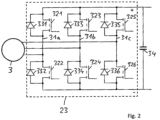
- the exemplary embodiment shown has four internal combustion engine-machine combinations 1, 3, the internal combustion engines 1a, 1b, 1c, 1d preferably being diesel engines.
- the electrical machines 3a, 3b, 3c, 3d are, for example, permanent magnet synchronous motors.
- Each of the combinations 1, 3 is connected via a three-phase connection line 4a, 4b, 4c, 4d to a generator-rectifier 5a, 5b, 5c, 5d assigned to the combination 1, 3.
- the three-phase connection line 4 of each of the combinations runs via a controllable three-phase disconnector 14a, 14b, 14c, 14d.
- the three-phase electrical connection between the electrical machine 3 and the generator rectifier 5 can be interrupted controlled by a control unit (not shown), in particular when the electrical machine 3 of the combination 1, 3 is operated as a motor, but also during a starting process Combination 1, 3.
- the rectifiers 5 are connected to the DC intermediate circuit with the lines 8, 10 via connecting lines 33, 34, which are designed as bus lines for all rectifiers 5.
- inverters that are connected to the lines 8, 10, for example at least one traction inverter, one auxiliary power inverter and one inverter for the traction power supply.
- each of the combinations there is an associated machine inverter 23a, 23b; 23c, 23d provided.
- the AC voltage sides of the machine inverters 23 are each connected to the three-phase connection line 4 of the combination via a switch 24a, 24b, 24c, 24d that can be controlled by a control unit (not shown).
- a capacitance CD is connected between the lines 8, 10 of the intermediate circuit in order to compensate for fluctuations in the direct voltage and/or to absorb energy.
- the DC voltage sides of the machine inverters 23 are connected to one another via a DC voltage connection 18.
- the DC voltage connection 18 is shown by individual lines, although it is a two-pole connection. However, it is possible for the DC voltage sides to be connected to one another, for example via a single-wire electrical line and also via vehicle ground. Since several combinations 1, 3 are present, the DC voltage connection 18 is branched.
- another electrical line 28 is connected to the DC voltage connection 18 in particular is designed as two-pole and allows energy to be taken from an electrical energy storage device 19 (eg vehicle battery) via a switch 27 and a voltage converter 26 as well as via an optional circuit breaker 25.
- the operation of at least one of the machine inverters 23 is therefore also possible with energy from the electrical energy storage 19.
- energy is taken from the electrical energy storage 19 to start the first internal combustion engine and used to start at least one combination 1, 3.
- the combination 1a, 3a is first started, then its electrical machine 3a is operated as a generator and the electrical energy generated is fed into the intermediate circuit 8, 10 via the generator rectifier 5b. It is therefore available for the operation of at least one traction motor and optionally other consumers from the intermediate circuit.
- the energy generated by the electric machine 3a can be fed into the DC voltage connection 18 via the associated machine inverter 23a and is available for the start of one or more other combinations 1, 3.
- the voltage converter 26 is also connected via an electrical line to the line 10 at the higher electrical potential of the intermediate circuit, namely via a resistor 29 and a diode 30.
- the line 22 can be separated from the voltage converter 26 by the switch 27.
- the DC intermediate circuit (in particular the capacitance CD) can be precharged via line 22, i.e. a corresponding electrical voltage can be generated between line 10 and line 8. As a result, very high electrical currents are avoided when the generators 3 are switched on by closing the switches 14.
- Fig. 1 Numerous modifications are possible in the arrangement shown. For example, there may be a different number of combinations 1, 3. Alternatively or additionally, several DC intermediate circuits can be provided, from which at least one traction motor is supplied with electrical energy. Alternatively or additionally, modifications can be made to the devices for feeding energy from the energy storage 19 into the DC voltage connection 18, for example at least one further voltage converter can be connected in parallel to the voltage converter 26 shown in FIG or can simultaneously provide electrical energy via one or more voltage converters.
- Fig. 2 shows an exemplary embodiment of a machine power converter or machine inverter, in particular each of the in Fig. 1 machine inverter 23 shown can be. Left in Fig. 2 the associated electrical machine 3 is shown, with the optional electrical switch 24 off Fig. 1 in Fig. 2 is not shown.
- the electrical machine 3 is connected via a three-phase electrical line which is in Fig. 1 is shown as a branch of line 4, connected to the AC voltage side of the machine converter 23.
- the power converter 23 is made up of three half-bridges 31a, 31b, 31c, each of which is formed by a series connection of two parallel connections, each of a controllable electronic switch 321-326 and a diode 331-336 connected in anti-parallel to it.
- the contact of the AC voltage connection between the parallel circuits connected in series is located in each half bridge 31a, 31b, 31c.
- the opposite ends of the half bridges 31 are each routed to one of two common poles of the DC voltage connection, which are in Fig. 2 are marked with a plus sign and a minus sign.
- a capacitance 34 is connected between these poles or different electrical potentials.
- the two poles of the DC voltage connection are connected to a DC voltage connection, via which the power converter 23 can be supplied with direct current and can preferably also supply other devices with direct current, depending on the operating state in which the electrical machine is.
- the control of the electronic valves 321-326 (which are preferably IGBTs) is also carried out or not carried out.
- the inverter operation of the power converter 23 is blocked (in particular, the electronic valves are then all switched off) when the electrical machine 3 cannot be supplied with alternating current from the power converter 23.
- the alternating current is due to the diodes 331-336 of the power converter 23 rectified and, in accordance with the linked alternating voltages of the three phases, a direct current results on the direct voltage side of the converter 23, the voltage fluctuations of which are smoothed out by the capacitance 34.
- the electrical potentials at the respective contacts of the AC voltage connection of the power converter 23 are temporarily greater than the electrical potentials at the positive pole of the DC voltage connection in each period of the alternating current, so that the diodes 331, 333, 335 become correspondingly electrically conductive.
- the electrical potential at the AC voltage contacts is temporarily lower in each period than the electrical potential at the second pole of the DC voltage connection, so that the diodes 332, 334, 336 temporarily become electrically conductive.
- each of the machine power converters 23 a capacitance is connected between the poles of the DC voltage connection, the capacitances preferably being chosen to be the same size.
- the total capacity present in the DC voltage connection of the machine converters is therefore at least as large as the number of connected machine converters multiplied by the individual capacity. Significant energy can therefore be stored in the capacities and is available to supply the machine power converters to one another.
- the smoothing of voltage fluctuations in the DC voltage connection is improved.
- energy is preferably not only drawn from the capacities of the DC voltage connection, but energy is additionally fed into the DC voltage connection from at least one of the other combinations during the starting process.
- the voltage level can be higher due to the supply of electrical energy from at least one of the electrical machines of the combinations in the DC voltage connection than if the DC voltage connection exclusively draws energy from the energy storage 19 of the vehicle.
- the voltage level at the storage-side input of the voltage converter 26 is approximately 110 V and the voltage converter increases this voltage at its output to a voltage level in the range of 750 V.
- this increased voltage level is in particular lower than the later voltage level in the DC voltage connection 18, which can be achieved when energy is fed in via one or more of the machine converters 23.
- Starting processes or other supplies of the various combinations 1, 3 to each other can therefore take place at a higher voltage level and thus faster and with higher energy flows than when supplied exclusively from the vehicle's energy storage. In particular, all existing combinations can therefore be started faster and more effectively than if starting energy is obtained exclusively from the energy storage 19.
- the electrical switches 14 are open and the electrical machines 3 are therefore still electrically isolated from the DC intermediate circuit 8, 10.
- the switch 27 is preferably first closed in order to connect the output of the voltage converter 26 to the DC voltage connections of the machine power converter 23 and at the same time to the DC intermediate circuit 8, 10.
- the blocking diode 30 is located in the electrical line 22 in order to protect against excessive voltage when the intermediate circuit is in operation after the internal combustion engines have started.
- the at least one voltage converter 26 can be switched on and after switching on the optional circuit breaker 25, the energy storage 19 or the voltage converter 26 loads the capacitances CD into the intermediate circuit 8, 10 and not into them Fig. 1 Capacitances shown at the connections of the DC voltage connection 18.
- the capacity CD By charging the capacity CD, the arrangement is protected from excessive currents that could occur without precharging the capacity after at least one of the switches 14 is switched on.
- the direct voltage at the output of the voltage converter 26 can initially be low and then increased over time.
- the starting process of a first internal combustion engine begins.
- the switch 25 in the electrical line between the machine power converter 23 of the combination is closed and the machine power converter 23 is controlled so that an alternating voltage is generated on its AC voltage side and an alternating current flows to the associated electrical machine 3.
- the control of the internal combustion engine can be put into a ready-to-start state.
- the machine converter 23 of the combination to be started is controlled in such a way that the alternating current generated by it generates a rotating field in the associated electrical machine 3 in the direction of rotation in which the coupled operation of the internal combustion engine and the electrical machine is to take place.
- the frequency of this alternating current is preferably increased over time in order to first set the internal combustion engine in motion from rest and then accelerate it.
- the internal combustion engine control unit automatically begins supplying fuel to the internal combustion engine, so that the internal combustion engine itself contributes to further acceleration.
- the motor inverter 23 is blocked, ie it no longer generates alternating current.
- the electronic switches are permanently switched off.
- the switch 27 can be opened again, so that no further energy is drawn from the energy storage 19. At the same time or alternatively, the voltage converter 26 is switched off.
- the starting process is continued by the internal combustion engine independently increasing its speed, in particular until an idling speed is reached.
- the first predetermined speed value is, for example, 120 per minute
- the second predetermined speed value is, for example, 400 per minute
- the idle speed is, for example, approximately 600 per minute.
- the alternating voltage generated by the associated electrical machine also increases. Therefore, if the switch 24 remains closed or is closed again, the alternating electrical voltage at the alternating voltage terminal of the machine power converter increases and causes the electrical one-way valves (in particular the diodes 331-336 in Fig. 2 ) become cyclically conductive, so that the machine power converter 23 generates a direct current on its DC voltage side. The corresponding electrical energy is now available for further charging of the capacities in the DC voltage connection and in particular at the same time or later for starting at least one further internal combustion engine. By closing the respective electrical switch 24 and activating the associated machine power converter 23, in particular in the same or similar manner as described above, the internal combustion engine of the respective combination 1, 3 is started.
- the electrical switches 14 can be closed either when all internal combustion engines have been started or when those combinations intended for operation have been started. Electrical energy then begins to be fed from the respective electrical machine 3 via the closed switch 14 and the associated rectifier 5 into the DC intermediate circuit 8, 10. Alternatively, at least one of the electrical switches 14 can be closed earlier. This can happen in particular if the capacitance CD in the DC intermediate circuit 8, 10 has already been precharged and, for example, one or more of the combinations 1, 3 have already been started and are generating electrical energy. Alternatively, this can also happen at an earlier point in time when the electrical alternating voltage generated by the electric machine 3 of a started combination 1, 3 is still low, i.e. the speed of the internal combustion engine 1 is still low. In this case too, excessive currents are prevented by charging the still empty capacity CD.
- At least one further combination 1, 3 can be started again with energy from the energy storage 19 and/or at least one combination 1, 3 that has not yet been started can be started with energy from an already started combination.
- both the switch 24 of the already started combination and the switch 24 of the combination to be started are closed and the machine power converter 23 of the combination to be started is supplied with direct current which was generated from alternating current which was generated by the electric machine of the already started combination .
- this at least one further combination is preferably started with energy from a combination that has already been started.
Claims (4)
- Ensemble servant à alimenter en énergie électrique des moteurs de traction électriques dans un véhicule sur rails, dans lequel l'ensemble présente :- au moins deux moteurs à combustion interne (1),- pour les au moins deux moteurs à combustion interne (1), respectivement une machine électrique (3) associée servant à produire de l'énergie électrique, dans lequel la machine électrique (3) est couplée de manière mécanique au moteur à combustion interne (1) de sorte qu'elle soit entraînée par le moteur à combustion interne (1) lors d'un mode de fonctionnement en générateur de la machine électrique (3) de sorte qu'au moins une première et une deuxième combinaison de machines de moteur à combustion interne soient formées,- au moins un raccordement de traction électrique, par l'intermédiaire duquel un moteur de traction du véhicule sur rails peut être relié de manière électrique à au moins une première des machines électriques (3), dans lequel le moteur de traction peut être alimenté en énergie électrique par la première machine électrique (3) par l'intermédiaire d'un circuit intermédiaire de tension continue (8, 10) de l'ensemble,- pour les machines électriques (3), respectivement un convertisseur de puissance de machine (23) associé servant à alimenter en énergie électrique la machine électrique (3) au cours d'un mode de fonctionnement en moteur de la machine électrique (3), dans lequel un raccordement de tension alternative du convertisseur de puissance de machine (23) est relié à la machine électrique (3), et- un ensemble de commande servant à commander au moins le fonctionnement des convertisseurs de puissance de machine, dans lequel la première machine électrique (3a) est reliée de manière électrique à un raccordement de tension alternative d'un redresseur (23a),dans lequel l'ensemble présente en plus des convertisseurs de puissance de machines (23) un redresseur de générateur (5a) destiné à redresser des courants alternatifs, qui sont produits par la première machine électrique (3a) au cours d'un mode de fonctionnement en générateur de la première machine électrique (3a), dans lequel le redresseur de générateur (5a) est relié, sur son côté de tension alternative, à la première machine électrique (3a) et est relié, sur son côté de tension continue, au circuit intermédiaire de tension continu (8, 10),le redresseur (23a) est le premier convertisseur de puissance de machine associé à la première machine électrique et présente des commutateurs électroniques pouvant être commandés, dans lequel respectivement au moins une soupape unidirectionnelle électrique est disposée de manière antiparallèle par rapport aux commutateurs électroniques pouvant être commandés du premier convertisseur de puissance de machine (23a), qui permettent la fonction d'onduleur de sorte que les soupapes unidirectionnelles électriques redressent le courant alternatif produit par la première machine électrique (3a),dans lequel un raccordement de tension continue du redresseur (23a) est relié de manière électrique, par l'intermédiaire d'une ligne de tension continue électrique (18), à un côté de tension continue d'un deuxième (23b) des convertisseurs de puissance de machine, qui est associé à une deuxième (3b) des machines électriques,dans lequel le redresseur (23a) redresse le courant alternatif électrique produit par la première machine électrique (3a) et l'amène, par l'intermédiaire de la ligne de tension continue (18), au deuxième convertisseur de puissance de machine (23b), et l'ensemble de commande est configuré de telle manière qu'il fait fonctionner le deuxième convertisseur de puissance de machine (23b) en tant qu'onduleur afin d'alimenter en courant alternatif la deuxième machine électrique (3b), tandis que le deuxième convertisseur de puissance de machine (23b) est alimenté en courant continu par le redresseur (23a),et la première machine électrique (3a) est séparée de manière électrique du circuit intermédiaire de tension continue (8, 10) au moyen d'un commutateur électrique (14a), tandis qu'elle alimente en énergie électrique la deuxième machine électrique (3b) par l'intermédiaire de la ligne de tension continue (18).
- Ensemble selon la revendication 1, dans lequel au moins une capacité électrique est branchée entre les différents potentiels électriques de la ligne de tension continue (18) et/ou entre les différents potentiels électriques d'un raccordement de tension continue du redresseur (23a) et/ou d'un raccordement de tension continue au moins d'un des convertisseurs de puissance de machine (23).
- Procédé servant à alimenter en énergie électrique des moteurs de traction électriques dans un véhicule sur rails, dans lequel :- au moins deux moteurs à combustion interne (1) fonctionnent respectivement en combinaison avec une machine électrique (3) associée de sorte qu'au moins une première et une deuxième combinaison de machines de moteur à combustion interne fonctionnent,- au moins une première (3a) des machines électriques (3) produit, entraînée par le moteur à combustion interne, un courant alternatif dans un premier état de fonctionnement de la machine au cours d'un mode de générateur de la machine électrique (3) respective, lequel courant alternatif est redressé par un redresseur de générateur (5a) et est utilisé pour un mode de fonctionnement au moins d'un moteur de traction électrique par l'intermédiaire d'un circuit intermédiaire de tension continue (8, 10),au moins une deuxième (3b) des machines électriques (3) est alimentée en courant alternatif par un convertisseur de puissance de machine (23b) qui lui est associé dans un deuxième état de fonctionnement de la machine et entraîne le moteur à combustion interne (1) qui lui est associé, au moins le convertisseur de puissance de machine (23b) associé à la deuxième machine électrique (3b) est alimenté, par l'intermédiaire d'une ligne de tension continue (18) électrique en courant continu par un redresseur (23a) associé à la première machine électrique (3a) alors que la machine électrique associée se trouve dans le deuxième état de fonctionnement,dans lequel le redresseur (23a) est un premier convertisseur de puissance de machine associé à la première machine électrique, présente des commutateurs électroniques pouvant être commandés, dans lequel respectivement au moins une soupape unidirectionnelle électrique est disposée de manière antiparallèle par rapport aux commutateurs électroniques pouvant être commandés du premier convertisseur de puissance de machine (23a), qui permettent la fonction d'onduleur de sorte que les soupapes unidirectionnelles redressent le courant alternatif produit par la première machine électrique (3a), et produit à partir du courant alternatif le courant continu, qui est produit par la première machine électrique (3a), etdans lequel la première machine électrique (3a) est séparée de manière électrique du circuit intermédiaire de tension continue (8, 10), tandis qu'elle alimente en énergie électrique la deuxième machine électrique (3b) par l'intermédiaire de la ligne de tension continue (18).
- Procédé selon la revendication 3, dans lequel dans un premier temps au moins une capacité électrique, qui est branchée entre les potentiels électriques de la ligne de tension continue (18), est chargée en énergie électrique, et seulement après une machine électrique (3) est alimentée en un courant continu inversé provenant de la ligne de tension continue (18) et/ou provenant de l'au moins une capacité.
Applications Claiming Priority (2)
| Application Number | Priority Date | Filing Date | Title |
|---|---|---|---|
| DE102013200019.7A DE102013200019B4 (de) | 2013-01-02 | 2013-01-02 | Versorgung von elektrischen Traktionsmotoren eines Schienenfahrzeugs mit elektrischer Energie unter Verwendung einer Mehrzahl von Verbrennungsmotoren |
| PCT/EP2014/050029 WO2014106637A2 (fr) | 2013-01-02 | 2014-01-02 | Alimentation en énergie électrique de moteurs électriques de propulsion d'un véhicule ferroviaire à l'aide d'une pluralité de moteurs à combustion |
Publications (3)
| Publication Number | Publication Date |
|---|---|
| EP2941363A2 EP2941363A2 (fr) | 2015-11-11 |
| EP2941363B1 EP2941363B1 (fr) | 2016-12-21 |
| EP2941363B2 true EP2941363B2 (fr) | 2023-09-13 |
Family
ID=49949656
Family Applications (1)
| Application Number | Title | Priority Date | Filing Date |
|---|---|---|---|
| EP14700139.0A Active EP2941363B2 (fr) | 2013-01-02 | 2014-01-02 | Alimentation en énergie électrique de moteurs électriques de propulsion d'un véhicule ferroviaire à l'aide d'une pluralité de moteurs à combustion |
Country Status (7)
| Country | Link |
|---|---|
| US (1) | US9637007B2 (fr) |
| EP (1) | EP2941363B2 (fr) |
| BR (1) | BR112015015247A2 (fr) |
| DE (1) | DE102013200019B4 (fr) |
| ES (1) | ES2617695T3 (fr) |
| PL (1) | PL2941363T5 (fr) |
| WO (1) | WO2014106637A2 (fr) |
Families Citing this family (7)
| Publication number | Priority date | Publication date | Assignee | Title |
|---|---|---|---|---|
| DE102011012164A1 (de) * | 2011-02-23 | 2012-08-23 | Bombardier Transportation Gmbh | Anordnung und Verfahren zum Versorgen von elektrischen Traktionsmotoren in einem Schienenfahrzeug, insbesondere in einem Zugverband, mit elektrischer Energie |
| US9346363B2 (en) * | 2012-08-13 | 2016-05-24 | Mitsubishi Electric Corporation | Propulsion control apparatus of engine hybrid railroad vehicle |
| CN105720830A (zh) * | 2014-12-02 | 2016-06-29 | 永济新时速电机电器有限责任公司 | 带母线电压接地保护分压采样电路的牵引变流器 |
| DE102015203137A1 (de) * | 2015-02-20 | 2016-08-25 | Mtu Friedrichshafen Gmbh | Kraftfahrzeug mit wenigstens zwei Leistungserzeugern zur Erzeugung von Antriebsleistung und Verfahren zum Betreiben eines solchen Kraftfahrzeugs |
| DE102015115649A1 (de) * | 2015-09-16 | 2017-03-16 | Claas Tractor Sas | Landwirtschaftliches Arbeitsfahrzeug |
| CN110341454A (zh) * | 2019-07-11 | 2019-10-18 | 山西成功汽车制造有限公司 | 一种双发动机混合动力重型车驱动系统及其使用方法 |
| WO2021121890A1 (fr) * | 2019-12-16 | 2021-06-24 | Siemens Mobility GmbH | Procédé de commande de la sortie de courant d'une batterie |
Family Cites Families (13)
| Publication number | Priority date | Publication date | Assignee | Title |
|---|---|---|---|---|
| US7231877B2 (en) * | 2001-03-27 | 2007-06-19 | General Electric Company | Multimode hybrid energy railway vehicle system and method |
| WO2005086910A2 (fr) * | 2004-03-08 | 2005-09-22 | Railpower Technologies Corp. | Configuration de locomotive hybride |
| US7940016B2 (en) | 2004-08-09 | 2011-05-10 | Railpower, Llc | Regenerative braking methods for a hybrid locomotive |
| US7304445B2 (en) * | 2004-08-09 | 2007-12-04 | Railpower Technologies Corp. | Locomotive power train architecture |
| US7518254B2 (en) | 2005-04-25 | 2009-04-14 | Railpower Technologies Corporation | Multiple prime power source locomotive control |
| US20080082247A1 (en) * | 2006-08-31 | 2008-04-03 | National Railway Equipment Co. | Engine start/stop control for multiple engine ohv based on operating statistics |
| DE102006042945B4 (de) * | 2006-09-13 | 2011-07-21 | Siemens AG, 80333 | Verfahren zur Effizienzsteigerung von dieselelektrisch getriebenen Fahrzeugen und Fahrzeug zur Durchführung des Verfahrens |
| US7710081B2 (en) * | 2006-10-27 | 2010-05-04 | Direct Drive Systems, Inc. | Electromechanical energy conversion systems |
| US7667347B2 (en) * | 2007-01-24 | 2010-02-23 | Railpower, Llc | Multi-power source locomotive control method and system |
| DE102007060893A1 (de) | 2007-12-14 | 2009-06-25 | Bombardier Transportation Gmbh | Anordnung zur Versorgung von Einrichtungen einer Lokomotive mit elektrischer Energie und Verfahren zum Betreiben der Anordnung |
| US8330291B2 (en) * | 2009-10-02 | 2012-12-11 | General Electric Company | Power generation apparatus |
| DE102011012164A1 (de) | 2011-02-23 | 2012-08-23 | Bombardier Transportation Gmbh | Anordnung und Verfahren zum Versorgen von elektrischen Traktionsmotoren in einem Schienenfahrzeug, insbesondere in einem Zugverband, mit elektrischer Energie |
| DE102012211543A1 (de) * | 2012-07-03 | 2014-01-09 | Bombardier Transportation Gmbh | Versorgung von elektrischen Traktionsmotoren und zusätzlichen elektrischen Hilfsbetrieben eines Schienenfahrzeugs mit elektrischer Energie |
-
2013
- 2013-01-02 DE DE102013200019.7A patent/DE102013200019B4/de active Active
-
2014
- 2014-01-02 US US14/655,221 patent/US9637007B2/en active Active
- 2014-01-02 ES ES14700139.0T patent/ES2617695T3/es active Active
- 2014-01-02 BR BR112015015247A patent/BR112015015247A2/pt not_active IP Right Cessation
- 2014-01-02 WO PCT/EP2014/050029 patent/WO2014106637A2/fr active Application Filing
- 2014-01-02 EP EP14700139.0A patent/EP2941363B2/fr active Active
- 2014-01-02 PL PL14700139.0T patent/PL2941363T5/pl unknown
Also Published As
| Publication number | Publication date |
|---|---|
| US20150343910A1 (en) | 2015-12-03 |
| ES2617695T3 (es) | 2017-06-19 |
| DE102013200019A1 (de) | 2014-07-03 |
| US9637007B2 (en) | 2017-05-02 |
| PL2941363T3 (pl) | 2017-07-31 |
| EP2941363B1 (fr) | 2016-12-21 |
| PL2941363T5 (pl) | 2024-01-03 |
| EP2941363A2 (fr) | 2015-11-11 |
| WO2014106637A3 (fr) | 2015-01-08 |
| DE102013200019B4 (de) | 2021-09-30 |
| WO2014106637A2 (fr) | 2014-07-10 |
| BR112015015247A2 (pt) | 2017-07-11 |
Similar Documents
| Publication | Publication Date | Title |
|---|---|---|
| EP2941363B2 (fr) | Alimentation en énergie électrique de moteurs électriques de propulsion d'un véhicule ferroviaire à l'aide d'une pluralité de moteurs à combustion | |
| DE19857645B4 (de) | Elektrisches System für Elektrofahrzeug | |
| EP2870020B1 (fr) | Alimentation en énergie électrique de moteurs électriques de traction et d'auxiliaires électriques additionnels d'un véhicule ferroviaire | |
| DE102011089297B4 (de) | Energiespeichereinrichtung, System mit Energiespeichereinrichtung und Verfahren zum Ansteuern einer Energiespeichereinrichtung | |
| EP2996898B1 (fr) | Unité d'entraînement pour la commande d'un moteur | |
| DE102016114101A1 (de) | Transformatorloses stromisoliertes bordladegerät mit festkörper-schaltersteuerung | |
| EP2678184B1 (fr) | Système et procédé d'alimentation en énergie électrique de moteurs de traction électriques dans un véhicule sur rails, en particulier dans un convoi | |
| DE10244229A1 (de) | Stromversorgungssystem und Stromversorgungsverfahren | |
| WO2010069830A1 (fr) | Agencement de propulsion pour véhicule à propulsion électrique | |
| DE102016103041A1 (de) | Leistungsumwandlungsvorrichtung | |
| DE112008000378T5 (de) | Generatorantriebsvorrichtung, Hybridfahrzeug und Steuerungsverfahren für die Generatorantriebsvorrichtung | |
| EP3634803B1 (fr) | Source de puissance pour un vehicule ferroviare | |
| DE102008026852A1 (de) | Wechselrichter mit zwei Quellen | |
| EP2707245B1 (fr) | Dispositif électronique de puissance et procédé de commande pour un moteur électrique et des accumulateurs d'énergie électriques | |
| WO2014140068A2 (fr) | Procédé et dispositif de fonctionnement d'un réseau de bord | |
| DE102012007158A1 (de) | Pulswechselrichter mit Stromzwischenkreis zum Fahren und Laden eines batteriebetriebenen Elektrofahrzeugs | |
| DE102010047338B4 (de) | Kraftfahrzeug mit Schaltungsanordnung sowie Verfahren zum Betreiben eines solchen Kraftfahrzeugs | |
| DE102010025266A1 (de) | Transportfahrzeug mit einer Mehrzahl elektrischer Maschinen | |
| WO2023006729A1 (fr) | Système d'entraînement électrique pour véhicule et procédé pour faire fonctionner un système d'entraînement électrique correspondant | |
| WO2011101195A1 (fr) | Prolongateur d'autonomie pour un véhicule entraîné par un moteur électrique | |
| WO2016180699A1 (fr) | Module de commutation de réseau de bord, dispositif d'assistance de réseau de bord et branche de réseau de bord | |
| EP3184349A1 (fr) | Systeme d'alimentation en energie d'un vehicule et vehicule comprenant un systeme de traction electrique | |
| WO2017220233A1 (fr) | Réseau électrique de bord de véhicule à moteur, doté d'au moins deux accumulateurs d'énergie, procédé pour faire fonctionner un réseau électrique de bord et moyens pour sa mise en oeuvre | |
| DE102018214830A1 (de) | Verfahren zum Betreiben eines Bordnetzes | |
| AT15560U1 (de) | Elektronischer Leistungswandler |
Legal Events
| Date | Code | Title | Description |
|---|---|---|---|
| PUAI | Public reference made under article 153(3) epc to a published international application that has entered the european phase |
Free format text: ORIGINAL CODE: 0009012 |
|
| 17P | Request for examination filed |
Effective date: 20150630 |
|
| AK | Designated contracting states |
Kind code of ref document: A2 Designated state(s): AL AT BE BG CH CY CZ DE DK EE ES FI FR GB GR HR HU IE IS IT LI LT LU LV MC MK MT NL NO PL PT RO RS SE SI SK SM TR |
|
| AX | Request for extension of the european patent |
Extension state: BA ME |
|
| DAX | Request for extension of the european patent (deleted) | ||
| RIC1 | Information provided on ipc code assigned before grant |
Ipc: H02J 1/10 20060101ALI20160519BHEP Ipc: B60L 15/00 20060101ALI20160519BHEP Ipc: H02J 1/00 20060101ALI20160519BHEP Ipc: B60L 15/32 20060101ALI20160519BHEP Ipc: B61C 3/00 20060101ALI20160519BHEP Ipc: B60L 11/08 20060101AFI20160519BHEP Ipc: H02M 1/00 20060101ALI20160519BHEP Ipc: B60L 3/00 20060101ALI20160519BHEP Ipc: B60W 10/08 20060101ALI20160519BHEP Ipc: B60K 5/08 20060101ALI20160519BHEP Ipc: B60W 10/06 20060101ALI20160519BHEP Ipc: B60K 6/20 20071001ALI20160519BHEP |
|
| GRAP | Despatch of communication of intention to grant a patent |
Free format text: ORIGINAL CODE: EPIDOSNIGR1 |
|
| INTG | Intention to grant announced |
Effective date: 20160713 |
|
| GRAS | Grant fee paid |
Free format text: ORIGINAL CODE: EPIDOSNIGR3 |
|
| STAA | Information on the status of an ep patent application or granted ep patent |
Free format text: STATUS: GRANT OF PATENT IS INTENDED |
|
| GRAA | (expected) grant |
Free format text: ORIGINAL CODE: 0009210 |
|
| STAA | Information on the status of an ep patent application or granted ep patent |
Free format text: STATUS: THE PATENT HAS BEEN GRANTED |
|
| AK | Designated contracting states |
Kind code of ref document: B1 Designated state(s): AL AT BE BG CH CY CZ DE DK EE ES FI FR GB GR HR HU IE IS IT LI LT LU LV MC MK MT NL NO PL PT RO RS SE SI SK SM TR |
|
| REG | Reference to a national code |
Ref country code: GB Ref legal event code: FG4D Free format text: NOT ENGLISH |
|
| REG | Reference to a national code |
Ref country code: CH Ref legal event code: EP |
|
| REG | Reference to a national code |
Ref country code: IE Ref legal event code: FG4D Free format text: LANGUAGE OF EP DOCUMENT: GERMAN |
|
| REG | Reference to a national code |
Ref country code: AT Ref legal event code: REF Ref document number: 855158 Country of ref document: AT Kind code of ref document: T Effective date: 20170115 |
|
| REG | Reference to a national code |
Ref country code: FR Ref legal event code: PLFP Year of fee payment: 4 |
|
| REG | Reference to a national code |
Ref country code: DE Ref legal event code: R096 Ref document number: 502014002256 Country of ref document: DE |
|
| REG | Reference to a national code |
Ref country code: DE Ref legal event code: R026 Ref document number: 502014002256 Country of ref document: DE |
|
| PLBI | Opposition filed |
Free format text: ORIGINAL CODE: 0009260 |
|
| PG25 | Lapsed in a contracting state [announced via postgrant information from national office to epo] |
Ref country code: LV Free format text: LAPSE BECAUSE OF FAILURE TO SUBMIT A TRANSLATION OF THE DESCRIPTION OR TO PAY THE FEE WITHIN THE PRESCRIBED TIME-LIMIT Effective date: 20161221 |
|
| 26 | Opposition filed |
Opponent name: STADLER RAIL AG Effective date: 20170208 |
|
| REG | Reference to a national code |
Ref country code: SE Ref legal event code: TRGR |
|
| REG | Reference to a national code |
Ref country code: LT Ref legal event code: MG4D |
|
| REG | Reference to a national code |
Ref country code: NL Ref legal event code: MP Effective date: 20161221 |
|
| PG25 | Lapsed in a contracting state [announced via postgrant information from national office to epo] |
Ref country code: NO Free format text: LAPSE BECAUSE OF FAILURE TO SUBMIT A TRANSLATION OF THE DESCRIPTION OR TO PAY THE FEE WITHIN THE PRESCRIBED TIME-LIMIT Effective date: 20170321 Ref country code: LT Free format text: LAPSE BECAUSE OF FAILURE TO SUBMIT A TRANSLATION OF THE DESCRIPTION OR TO PAY THE FEE WITHIN THE PRESCRIBED TIME-LIMIT Effective date: 20161221 Ref country code: GR Free format text: LAPSE BECAUSE OF FAILURE TO SUBMIT A TRANSLATION OF THE DESCRIPTION OR TO PAY THE FEE WITHIN THE PRESCRIBED TIME-LIMIT Effective date: 20170322 |
|
| PG25 | Lapsed in a contracting state [announced via postgrant information from national office to epo] |
Ref country code: FI Free format text: LAPSE BECAUSE OF FAILURE TO SUBMIT A TRANSLATION OF THE DESCRIPTION OR TO PAY THE FEE WITHIN THE PRESCRIBED TIME-LIMIT Effective date: 20161221 Ref country code: RS Free format text: LAPSE BECAUSE OF FAILURE TO SUBMIT A TRANSLATION OF THE DESCRIPTION OR TO PAY THE FEE WITHIN THE PRESCRIBED TIME-LIMIT Effective date: 20161221 Ref country code: BE Free format text: LAPSE BECAUSE OF NON-PAYMENT OF DUE FEES Effective date: 20170131 Ref country code: HR Free format text: LAPSE BECAUSE OF FAILURE TO SUBMIT A TRANSLATION OF THE DESCRIPTION OR TO PAY THE FEE WITHIN THE PRESCRIBED TIME-LIMIT Effective date: 20161221 |
|
| REG | Reference to a national code |
Ref country code: ES Ref legal event code: FG2A Ref document number: 2617695 Country of ref document: ES Kind code of ref document: T3 Effective date: 20170619 |
|
| PG25 | Lapsed in a contracting state [announced via postgrant information from national office to epo] |
Ref country code: NL Free format text: LAPSE BECAUSE OF FAILURE TO SUBMIT A TRANSLATION OF THE DESCRIPTION OR TO PAY THE FEE WITHIN THE PRESCRIBED TIME-LIMIT Effective date: 20161221 |
|
| PG25 | Lapsed in a contracting state [announced via postgrant information from national office to epo] |
Ref country code: SK Free format text: LAPSE BECAUSE OF FAILURE TO SUBMIT A TRANSLATION OF THE DESCRIPTION OR TO PAY THE FEE WITHIN THE PRESCRIBED TIME-LIMIT Effective date: 20161221 Ref country code: RO Free format text: LAPSE BECAUSE OF FAILURE TO SUBMIT A TRANSLATION OF THE DESCRIPTION OR TO PAY THE FEE WITHIN THE PRESCRIBED TIME-LIMIT Effective date: 20161221 Ref country code: IS Free format text: LAPSE BECAUSE OF FAILURE TO SUBMIT A TRANSLATION OF THE DESCRIPTION OR TO PAY THE FEE WITHIN THE PRESCRIBED TIME-LIMIT Effective date: 20170421 Ref country code: EE Free format text: LAPSE BECAUSE OF FAILURE TO SUBMIT A TRANSLATION OF THE DESCRIPTION OR TO PAY THE FEE WITHIN THE PRESCRIBED TIME-LIMIT Effective date: 20161221 Ref country code: CZ Free format text: LAPSE BECAUSE OF FAILURE TO SUBMIT A TRANSLATION OF THE DESCRIPTION OR TO PAY THE FEE WITHIN THE PRESCRIBED TIME-LIMIT Effective date: 20161221 |
|
| PG25 | Lapsed in a contracting state [announced via postgrant information from national office to epo] |
Ref country code: BG Free format text: LAPSE BECAUSE OF FAILURE TO SUBMIT A TRANSLATION OF THE DESCRIPTION OR TO PAY THE FEE WITHIN THE PRESCRIBED TIME-LIMIT Effective date: 20170321 Ref country code: PT Free format text: LAPSE BECAUSE OF FAILURE TO SUBMIT A TRANSLATION OF THE DESCRIPTION OR TO PAY THE FEE WITHIN THE PRESCRIBED TIME-LIMIT Effective date: 20170421 Ref country code: SM Free format text: LAPSE BECAUSE OF FAILURE TO SUBMIT A TRANSLATION OF THE DESCRIPTION OR TO PAY THE FEE WITHIN THE PRESCRIBED TIME-LIMIT Effective date: 20161221 |
|
| REG | Reference to a national code |
Ref country code: CH Ref legal event code: PL |
|
| PG25 | Lapsed in a contracting state [announced via postgrant information from national office to epo] |
Ref country code: MC Free format text: LAPSE BECAUSE OF FAILURE TO SUBMIT A TRANSLATION OF THE DESCRIPTION OR TO PAY THE FEE WITHIN THE PRESCRIBED TIME-LIMIT Effective date: 20161221 |
|
| PG25 | Lapsed in a contracting state [announced via postgrant information from national office to epo] |
Ref country code: LI Free format text: LAPSE BECAUSE OF NON-PAYMENT OF DUE FEES Effective date: 20170131 Ref country code: CH Free format text: LAPSE BECAUSE OF NON-PAYMENT OF DUE FEES Effective date: 20170131 |
|
| REG | Reference to a national code |
Ref country code: IE Ref legal event code: MM4A |
|
| PLAX | Notice of opposition and request to file observation + time limit sent |
Free format text: ORIGINAL CODE: EPIDOSNOBS2 |
|
| PG25 | Lapsed in a contracting state [announced via postgrant information from national office to epo] |
Ref country code: DK Free format text: LAPSE BECAUSE OF FAILURE TO SUBMIT A TRANSLATION OF THE DESCRIPTION OR TO PAY THE FEE WITHIN THE PRESCRIBED TIME-LIMIT Effective date: 20161221 Ref country code: LU Free format text: LAPSE BECAUSE OF NON-PAYMENT OF DUE FEES Effective date: 20170102 |
|
| REG | Reference to a national code |
Ref country code: FR Ref legal event code: PLFP Year of fee payment: 5 |
|
| REG | Reference to a national code |
Ref country code: BE Ref legal event code: MM Effective date: 20170131 |
|
| PG25 | Lapsed in a contracting state [announced via postgrant information from national office to epo] |
Ref country code: SI Free format text: LAPSE BECAUSE OF FAILURE TO SUBMIT A TRANSLATION OF THE DESCRIPTION OR TO PAY THE FEE WITHIN THE PRESCRIBED TIME-LIMIT Effective date: 20161221 Ref country code: IE Free format text: LAPSE BECAUSE OF NON-PAYMENT OF DUE FEES Effective date: 20170102 |
|
| PLBB | Reply of patent proprietor to notice(s) of opposition received |
Free format text: ORIGINAL CODE: EPIDOSNOBS3 |
|
| GBPC | Gb: european patent ceased through non-payment of renewal fee |
Effective date: 20180102 |
|
| PG25 | Lapsed in a contracting state [announced via postgrant information from national office to epo] |
Ref country code: MT Free format text: LAPSE BECAUSE OF FAILURE TO SUBMIT A TRANSLATION OF THE DESCRIPTION OR TO PAY THE FEE WITHIN THE PRESCRIBED TIME-LIMIT Effective date: 20161221 |
|
| REG | Reference to a national code |
Ref country code: DE Ref legal event code: R079 Ref document number: 502014002256 Country of ref document: DE Free format text: PREVIOUS MAIN CLASS: B60L0011080000 Ipc: B60L0050130000 |
|
| PG25 | Lapsed in a contracting state [announced via postgrant information from national office to epo] |
Ref country code: GB Free format text: LAPSE BECAUSE OF NON-PAYMENT OF DUE FEES Effective date: 20180102 |
|
| RIC2 | Information provided on ipc code assigned after grant |
Ipc: B60L 11/08 20060101AFI20160519BHEP Ipc: B60W 10/08 20060101ALI20160519BHEP Ipc: B60K 5/08 20060101ALI20160519BHEP Ipc: B60L 15/32 20060101ALI20160519BHEP Ipc: B60L 15/00 20060101ALI20160519BHEP Ipc: B60L 3/00 20190101ALI20160519BHEP Ipc: H02J 1/00 20060101ALI20160519BHEP Ipc: H02M 1/00 20060101ALI20160519BHEP Ipc: B61C 3/00 20060101ALI20160519BHEP Ipc: B60W 10/06 20060101ALI20160519BHEP Ipc: H02J 1/10 20060101ALI20160519BHEP Ipc: B60K 6/20 20071001ALI20160519BHEP |
|
| PG25 | Lapsed in a contracting state [announced via postgrant information from national office to epo] |
Ref country code: HU Free format text: LAPSE BECAUSE OF FAILURE TO SUBMIT A TRANSLATION OF THE DESCRIPTION OR TO PAY THE FEE WITHIN THE PRESCRIBED TIME-LIMIT; INVALID AB INITIO Effective date: 20140102 |
|
| RIC2 | Information provided on ipc code assigned after grant |
Ipc: B60K 5/08 20060101ALI20190612BHEP Ipc: B60L 50/13 20190101AFI20190612BHEP Ipc: H02M 1/00 20060101ALI20190612BHEP Ipc: B60L 15/00 20060101ALI20190612BHEP Ipc: H02J 1/10 20060101ALI20190612BHEP Ipc: B60L 3/00 20190101ALI20190612BHEP |
|
| PG25 | Lapsed in a contracting state [announced via postgrant information from national office to epo] |
Ref country code: CY Free format text: LAPSE BECAUSE OF FAILURE TO SUBMIT A TRANSLATION OF THE DESCRIPTION OR TO PAY THE FEE WITHIN THE PRESCRIBED TIME-LIMIT Effective date: 20161221 |
|
| PG25 | Lapsed in a contracting state [announced via postgrant information from national office to epo] |
Ref country code: MK Free format text: LAPSE BECAUSE OF FAILURE TO SUBMIT A TRANSLATION OF THE DESCRIPTION OR TO PAY THE FEE WITHIN THE PRESCRIBED TIME-LIMIT Effective date: 20161221 |
|
| APBM | Appeal reference recorded |
Free format text: ORIGINAL CODE: EPIDOSNREFNO |
|
| APBP | Date of receipt of notice of appeal recorded |
Free format text: ORIGINAL CODE: EPIDOSNNOA2O |
|
| APAH | Appeal reference modified |
Free format text: ORIGINAL CODE: EPIDOSCREFNO |
|
| REG | Reference to a national code |
Ref country code: AT Ref legal event code: MM01 Ref document number: 855158 Country of ref document: AT Kind code of ref document: T Effective date: 20190102 |
|
| PG25 | Lapsed in a contracting state [announced via postgrant information from national office to epo] |
Ref country code: TR Free format text: LAPSE BECAUSE OF FAILURE TO SUBMIT A TRANSLATION OF THE DESCRIPTION OR TO PAY THE FEE WITHIN THE PRESCRIBED TIME-LIMIT Effective date: 20161221 |
|
| APBQ | Date of receipt of statement of grounds of appeal recorded |
Free format text: ORIGINAL CODE: EPIDOSNNOA3O |
|
| PG25 | Lapsed in a contracting state [announced via postgrant information from national office to epo] |
Ref country code: AT Free format text: LAPSE BECAUSE OF NON-PAYMENT OF DUE FEES Effective date: 20190102 |
|
| PG25 | Lapsed in a contracting state [announced via postgrant information from national office to epo] |
Ref country code: AL Free format text: LAPSE BECAUSE OF FAILURE TO SUBMIT A TRANSLATION OF THE DESCRIPTION OR TO PAY THE FEE WITHIN THE PRESCRIBED TIME-LIMIT Effective date: 20161221 |
|
| APBU | Appeal procedure closed |
Free format text: ORIGINAL CODE: EPIDOSNNOA9O |
|
| PGFP | Annual fee paid to national office [announced via postgrant information from national office to epo] |
Ref country code: FR Payment date: 20230124 Year of fee payment: 10 |
|
| PGFP | Annual fee paid to national office [announced via postgrant information from national office to epo] |
Ref country code: SE Payment date: 20230119 Year of fee payment: 10 Ref country code: IT Payment date: 20230120 Year of fee payment: 10 |
|
| PGFP | Annual fee paid to national office [announced via postgrant information from national office to epo] |
Ref country code: ES Payment date: 20230405 Year of fee payment: 10 |
|
| PUAH | Patent maintained in amended form |
Free format text: ORIGINAL CODE: 0009272 |
|
| STAA | Information on the status of an ep patent application or granted ep patent |
Free format text: STATUS: PATENT MAINTAINED AS AMENDED |
|
| 27A | Patent maintained in amended form |
Effective date: 20230913 |
|
| AK | Designated contracting states |
Kind code of ref document: B2 Designated state(s): AL AT BE BG CH CY CZ DE DK EE ES FI FR GB GR HR HU IE IS IT LI LT LU LV MC MK MT NL NO PL PT RO RS SE SI SK SM TR |
|
| REG | Reference to a national code |
Ref country code: DE Ref legal event code: R102 Ref document number: 502014002256 Country of ref document: DE |
|
| P01 | Opt-out of the competence of the unified patent court (upc) registered |
Effective date: 20230822 |
|
| REG | Reference to a national code |
Ref country code: SE Ref legal event code: RPEO |
|
| PGFP | Annual fee paid to national office [announced via postgrant information from national office to epo] |
Ref country code: PL Payment date: 20231222 Year of fee payment: 11 |
|
| PGFP | Annual fee paid to national office [announced via postgrant information from national office to epo] |
Ref country code: ES Payment date: 20240223 Year of fee payment: 11 |
|
| PG25 | Lapsed in a contracting state [announced via postgrant information from national office to epo] |
Ref country code: ES Free format text: LAPSE BECAUSE OF FAILURE TO SUBMIT A TRANSLATION OF THE DESCRIPTION OR TO PAY THE FEE WITHIN THE PRESCRIBED TIME-LIMIT Effective date: 20230913 |
|
| PG25 | Lapsed in a contracting state [announced via postgrant information from national office to epo] |
Ref country code: ES Free format text: LAPSE BECAUSE OF FAILURE TO SUBMIT A TRANSLATION OF THE DESCRIPTION OR TO PAY THE FEE WITHIN THE PRESCRIBED TIME-LIMIT Effective date: 20230913 |
|
| PGFP | Annual fee paid to national office [announced via postgrant information from national office to epo] |
Ref country code: DE Payment date: 20240119 Year of fee payment: 11 |