EP2018592B1 - System und verfahren zur ortung von geräten an kundenstandorten - Google Patents
System und verfahren zur ortung von geräten an kundenstandorten Download PDFInfo
- Publication number
- EP2018592B1 EP2018592B1 EP07760622.6A EP07760622A EP2018592B1 EP 2018592 B1 EP2018592 B1 EP 2018592B1 EP 07760622 A EP07760622 A EP 07760622A EP 2018592 B1 EP2018592 B1 EP 2018592B1
- Authority
- EP
- European Patent Office
- Prior art keywords
- cpe
- bts
- information
- timing
- location
- Prior art date
- Legal status (The legal status is an assumption and is not a legal conclusion. Google has not performed a legal analysis and makes no representation as to the accuracy of the status listed.)
- Not-in-force
Links
Images
Classifications
-
- H—ELECTRICITY
- H04—ELECTRIC COMMUNICATION TECHNIQUE
- H04W—WIRELESS COMMUNICATION NETWORKS
- H04W64/00—Locating users or terminals or network equipment for network management purposes, e.g. mobility management
-
- G—PHYSICS
- G01—MEASURING; TESTING
- G01S—RADIO DIRECTION-FINDING; RADIO NAVIGATION; DETERMINING DISTANCE OR VELOCITY BY USE OF RADIO WAVES; LOCATING OR PRESENCE-DETECTING BY USE OF THE REFLECTION OR RERADIATION OF RADIO WAVES; ANALOGOUS ARRANGEMENTS USING OTHER WAVES
- G01S5/00—Position-fixing by co-ordinating two or more direction or position line determinations; Position-fixing by co-ordinating two or more distance determinations
- G01S5/02—Position-fixing by co-ordinating two or more direction or position line determinations; Position-fixing by co-ordinating two or more distance determinations using radio waves
- G01S5/12—Position-fixing by co-ordinating two or more direction or position line determinations; Position-fixing by co-ordinating two or more distance determinations using radio waves by co-ordinating position lines of different shape, e.g. hyperbolic, circular, elliptical or radial
Definitions
- One of the value-added services supplied by wireless network service providers is to provide personalized services based on the location of a subscriber.
- the coordinates for a mobile customer premises equipment (CPE), obtained by using the Global Positioning System (GPS), are often shown in a latitude and longitude. This location information is valuable to network service providers.
- CPE mobile customer premises equipment
- GPS Global Positioning System
- network service providers can manage network resources more efficiently, support traffic monitoring more effectively, and develop a more economic frequency reuse plan.
- network service providers can deploy location-based applications, such as navigation services, E911 services, and real-time advertisement, based on the geographic location of a CPE.
- a session in the subscription-based wireless network defines a communication task between a base station (BTS) and a CPE.
- a session profile contains all but location information related to the session between the BTS and the CPE.
- the session profile includes information such as the power level of the physical layer, the frequency allocation of the medium access control layer, the provisioning parameters of quality of service, and accounting information.
- the CPE may support multiple sessions simultaneously.
- GPS coordinates for a location, the session profile, and the statistics information about the CPE facilitate the creation of new services, which, in turn, generate more revenues for network service providers.
- a conventional wireless communication system that provides location-based services requires multiple BTSs to gather information about a CPE and it also requires a back-end server to collect information about the CPE from all participating BTSs and determine the GPS location of the CPE. There are many ways to determine the location of a CPE, based on the information collected by multiple BTSs.
- An advantage of the invention is that it improves the prior art solutions by offering a better way to determine the GPS location of a CPE while the system only requires one BTS.
- US 6489923 discloses a system for estimating the position of a mobile station in terms of its bearing and range from a cell site.
- US 2003/0117320 discloses a method for determining a mobile station's location based on measuring the distance between a wireless base station and the mobile station and determining the mobile station's azimuth and elevation angles.
- a plurality of antennas in a base transceiver station receives signals transmitted from a customer premises equipment.
- a timing detection module extracts the timing offset from the receiving signals and a first calculation module calculates the distance between the BTS and the CPE based on the timing offset.
- a signal detection module detects magnitudes and phases of the receiving signals and a second calculation module determines a dominant beam according to the antenna pattern and calculates the direction of arrival of the dominant beam.
- a third calculation module calculates the location of the CPE relative to the BTS based on the distance and the direction of arrival.
- the present invention discloses a system for detecting locations of a CPE in a wireless communication system with one or more BTSs and one is sufficient.
- the present invention also discloses a method to more accurately determine the GPS coordinates for a CPE using one BTS equipped with an array of antennas.
- One of the embodiments of the present invention is a location-based service system adopting the disclosed method.
- the location-based service system utilizes the GPS location information about a CPE to provide better services and operate more efficiently.
- the method disclosed in the present invention determines the GPS coordinates for a CPE by deriving the DOA from the antenna beam pattern of a BTS and mapping the absolute Cartesian coordinates to the GPS coordinates for the CPE.
- the absolute Cartesian coordinates are determined by the following parameters: the distance between the BTS and the CPE, the DOA of the antenna beam, and the Cartesian coordinates for the BTS.
- the location-based service system described in the present invention only requires a single BTS to determine the GPS location of a CPE, facilitates the extracting of the data from the location information based on the GPS, and generates innovative applications to better serve the subscribers of the wireless network.
- the accuracy of the estimated GPS location will be improved with more BTSs participating in the process, but unlike a conventional system, the system disclosed in the invention does not require additional BTS.
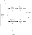
- FIG. 1 is a block diagram illustrating a system for detecting locations of a CPE.
- Block 110 is a plurality of antennas on a BTS. The plurality of antennas on the BTS receives signals transmitted from the CPE.
- Block 120 is a timing detection module that extracts a timing offset from receiving signals.
- Block 125 is a distance calculator that calculates the distance between the BTS and the CPE based on timing offset information.
- Block 130 is a signal detection module that detects magnitudes and phases of the antenna pattern of the receiving signals.
- Block 135 is a DOA calculator that determines a dominant beam of the antenna pattern and calculates the direction of arrival (DOA) of the signal from the dominant beam.
- Block 140 is a location server that calculates the location of the CPE relative to the BTS based on the data produced by blocks 125 and 135.
- FIG. 2 is a flow diagram illustrating the determination of the GPS coordinates for a CPE by a location server. There are four steps in the flow diagram.
- the CPE calculates a timing offset adjustment, which represents the sum of an open-loop timing adjustment and a close-loop timing adjustment, and subsequently reports it to the BTS.
- FIG. 3 further describes a method to calculate the timing offset of the CPE.
- the BTS collects magnitude and phase information about the receiving signal, transmitted from an array of antennas by the CPE.
- the BTS determines the DOA of the receiving signal based on the magnitude and phase information about the antenna beam pattern.
- the beam with the largest amplitude in the antenna beam pattern is designated as the dominant beam, the direction of which determines the DOA.
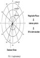
- FIG. 4 is a diagram of an antenna beam pattern.
- step 230 the BTS sends to a location server (LS) the timing offset, DOA, and session profile information about the CPE.
- the LS calculates the two dimensional Cartesian coordinates for the CPE based on the timing offset and DOA information.
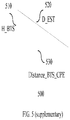
- FIG. 5 further describes the procedure to calculate the two dimensional Cartesian coordinates for the CPE.
- the location server maps the two dimensional Cartesian coordinates to the GPS coordinates; namely, latitude and longitude, for the CPE.
- the mapping involves geographic mathematics. Because the shape of the earth is slightly oblate, many approximation methods can be used to map the two dimensional Cartesian coordinates to the GPS coordinates for a location.
- One embodiment of the approximation is to let the longitude of the CPE equal to X_CPE_absolute and the latitude of the CPE equal to Y_CPE_absolute.
- the accuracy of the GPS coordinates for the CPE depends on the accuracy of the estimation of the distance between the BTS and the CPE and DOA.
- Several postprocessing procedures can be adopted to remove the erroneous information that is less accurate.
- SNR signal-to-noise-ratio
- the SNR filtering module eliminates the calculated DOA and distance information if the corresponding SNR is less than a given threshold.
- the beamforming filtering module eliminates the calculated DOA and distance information if the ratio of the amplitude of the dominant beam to the average amplitude of the rest of the beams is less than a given threshold.
- the speed filtering module it eliminates the calculated DOA and distance information if the speed of the CPE derived from the consecutive records is lager than a given threshold.
- the three filtering modules can be used individually or consecutively in a predetermined order.
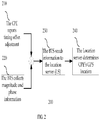
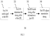
- FIG. 3 is a flow diagram of a close-loop adjustment.
- a CPE transmits a signal to the BTS at a scheduled time.
- the BTS determines the timing offset of the CPE.
- the BTS sends a timing offset adjustment message to the CPE.
- the CPE makes a timing correction by adjusting its transmission timing according to the received adjustment message when sending signals to the BTS afterwards.
- the CPE adjusts the timing offset according to some internal references. For example, if the downlink timing of the receiving signal is advanced by ⁇ t, the CPE will delay the uplink timing by the same amount ⁇ t. The CPE sums up the open-loop and close-loop timing offset adjustments and reports the result to the BTS.
- a conventional method to obtain DOA information is to apply the eigenvalue decomposition method to an antenna input correlation matrix.
- eigenvalue decomposition methods such as the Min-Norm method, the Multiple Signal Classification (MUSIC), and the Estimation of Signal Parameters via Rotational Invariance Techniques (ESPRIT).
- the method in the present invention obtains DOA information using the signals received by multiple antennas on a BTS.
- FIG. 4 is a diagram illustrating an antenna beam pattern of a BTS with respect to a CPE.
- the diagram shows the magnitude and direction of the detected beams.
- the beam with the largest amplitude is designated as the dominant beam whose direction is DOA.
- the DOA is 250 degrees.
- FIG. 5 is a supplementary diagram to explain how a location server calculates the two dimensional Cartesian coordinates for a CPE.
- the relative Cartesian coordinates for the CPE are determined by two values, and they are the distance between the BTS and the CPE and DOA.
- the accuracy of the estimation of a CPE location can be further improved by reporting the CPE location collaboratively by multiple BTSs.
- the BTSs in such a system could establish communication channels among themselves to exchange the location information about the CPE.
- the CPE communicates with one or more BTSs simultaneously.
- the geographic mathematics can also be applied to the estimation process to improve the accuracy of the estimation of the CPE location.
- the system disclosed in the invention comprises of multiple CPEs and one or more BTSs, one or more servers.
- the BTS gathers the distance and DOA information about the CPE and the associated session profile and send them to a server, for example a location server, to determine the CPE location.
- the server calculates the GPS coordinates for the CPE and modify the associated session profile and sends them to a server with development tools, for example an application server.
- the development tools in the server use the updated session profile and the GPS location information about the CPE to extract data that facilitates the creation of new services.
- One example of the data extracted from the session profile and the GPS location information is the moving-path of the CPE.
- An application can generate a plot to display the estimated and actual moving-paths of the CPE.
- the moving-path plot can help wireless network service providers to improve network resource planning.
- Wireless network service providers can develop numerous applications to exploit the data embedded in the GPS location information. For example, the space division multiple access (SDMA), the drop call analysis, the SNR/ traffic density geographic analysis, the geographic-information based power/bandwidth allocation, and the handoff assistance.
- SDMA space division multiple access
- the drop call analysis the SNR/ traffic density geographic analysis
- the geographic-information based power/bandwidth allocation the handoff assistance.
- New businesses can also be developed based on the information about the movement of CPEs to benefit the subscribers of the wireless network. These new businesses include, but not limited to, the CPE location-based Google map, the local business search, the advertisement, the E911, the navigation, and the real-time highway traffic report.
Landscapes
- Engineering & Computer Science (AREA)
- Computer Networks & Wireless Communication (AREA)
- Signal Processing (AREA)
- Physics & Mathematics (AREA)
- General Physics & Mathematics (AREA)
- Radar, Positioning & Navigation (AREA)
- Remote Sensing (AREA)
- Mobile Radio Communication Systems (AREA)
- Position Fixing By Use Of Radio Waves (AREA)
Claims (9)
- Drahtloses Kommunikationssystem, das aufweist:eine Vielzahl von Antennen (110) auf einer Basissendeempfängerstation bzw. Base Transceiver Station (BTS) zum Empfangen eines Signals, das von einem Endgerät beim Kunden bzw. Customer Premises Equipment (CPE) gesendet wird, die ein Antennenstrahlmuster mit einer Vielzahl von Strahlen hat;ein Timing-Detektionsmodul (120), das dazu konfiguriert ist, wenigstens einen Timing-Versatz aus wenigstens einem der Vielzahl von Strahlen zu extrahieren, wobei der Timing-Versatz durch Austauschen von Timing-Informationen zwischen der BTS und dem CPE erzeugt wird;ein erstes Berechnungsmodul (125), das dazu konfiguriert ist, einen Abstand zwischen dem BTS und dem CPE basierend auf dem Timing-Versatz zu berechnen;ein Signal-Detektionsmodul (130), das dazu konfiguriert ist, Größen und Phasen der Vielzahl von Strahlen zu erkennen;ein zweites Berechnungsmodul (135), das dazu konfiguriert ist, einen Strahl, der die größte Amplitude hat, als dominanten Strahl aus der Vielzahl von Strahlen auszuwählen und eine Ankunftsrichtung (Direction of Arrivial DOA) des Signals aus dem dominanten Strahl zu berechnen;ein drittes Berechnungsmodul (140), das dazu konfiguriert ist, den Standort des CPE bezüglich der BTS basierend auf der DOA zu berechnen; unddadurch gekennzeichnet, dass das System des Weiteren ein Strahlformungs-Filtermodul aufweist, das dazu konfiguriert ist, die berechneten DOA- und Abstandsinformationen zu entfernen, wenn das Verhältnis der Amplitude des dominanten Strahls zur Durchschnittsamplitude des Rests der Vielzahl von Strahlen kleiner als ein gegebener Schwellenwert ist.
- Drahtloses Kommunikationssystem nach Anspruch 1, wobei das Timing-Detektionsmodul den Timing-Versatz durch Verwenden von Timing-Anpassungsinformationen mit offener Schleife und geschlossener Schleife extrahiert.
- Drahtloses Kommunikationssystem nach Anspruch 1, das des Weiteren ein viertes Berechnungsmodul aufweist, das dazu konfiguriert ist, den relativen Standort des CPE in einen Satz von Breiten- und Längenkoordinaten basierend auf einem Standort der BTS umzuwandeln.
- Drahtloses Kommunikationssystem nach Anspruch 3, wobei die Umwandlung aufweist:Berechnen der absoluten kartesischen Koordinaten für das CPE; undAbbilden der absoluten kartesischen Koordinaten auf die Breiten- und Längenkoordinaten.
- Verfahren zum Ermitteln des Standorts eines Endgeräts beim Kunden bzw. Customer Premises Equipment (CPE) in einem drahtlosen Kommunikationsnetzwerk unter Verwendung einer empfangenen Vielzahl von Strahlen eines von dem CPE gesendeten Signals, wobei das Verfahren aufweist:Auswählen eines Strahls, der die größte Amplitude hat, als dominanten Strahl aus der Vielzahl von Strahlen;Bestimmen einer Ankunftsrichtung des Signals von dem dominanten Strahl;Bestimmen von Timing-Versatzdaten für das Endgerät beim Kunden , wobei die Timing-Versatzdaten durch Austauschen von Timing-Informationen zwischen einer Basissendeempfängerstation bzw. Base Transceiver Station (BTS) und dem CPE erzeugt werden;Berechnen eines Abstands zwischen der Basissendeempfängerstation und dem Endgerät beim Kunden basierend auf den Timing-Versatzdaten;Erhalten des Standorts des Endgeräts beim Kunden bezüglich der Basissendeempfängerstation basierend auf den Ankunftsrichtungs- und den Abstandsinformationen; unddadurch gekennzeichnet, dass das Verfahren des Weiteren aufweist:
Entfernen der berechneten Ankunftsrichtungs- und Abstandsinformationen, wenn das Verhältnis der Amplitude des dominanten Strahls zur Durchschnittsamplitude des Rests der Vielzahl von Strahlen kleiner als ein gegebener Schwellenwert ist. - Verfahren nach Anspruch 5, wobei die Timing-Versatzinformationen über das CPE des Weiteren Timing-Schätzungen mit offener Schleife und geschlossener Schleife aufweisen.
- Verfahren nach Anspruch 5, das des Weiteren aufweist:Berechnen der absoluten kartesischen Koordinaten für das CPE; undAbbilden der absoluten kartesischen Koordinaten auf Breiten- und Längenkoordinaten.
- Verfahren nach Anspruch 7, wobei das Berechnen der absoluten kartesischen Koordinaten auf Abstands- und Ankunftsrichtungsinformationen basiert.
- Verfahren nach Anspruch 7, wobei das Abbilden der absoluten kartesischen Koordinaten auf die Breiten- und Längenkoordinaten des Weiteren geographisches Berechnen beinhaltet.
Applications Claiming Priority (3)
| Application Number | Priority Date | Filing Date | Title |
|---|---|---|---|
| US80193606P | 2006-05-19 | 2006-05-19 | |
| US11/734,670 US7706812B2 (en) | 2006-05-19 | 2007-04-12 | System and method for detecting locations of a customer premises equipment |
| PCT/US2007/066603 WO2007136945A2 (en) | 2006-05-19 | 2007-04-13 | System and method for detecting locations of a customer premises equipment |
Publications (3)
| Publication Number | Publication Date |
|---|---|
| EP2018592A2 EP2018592A2 (de) | 2009-01-28 |
| EP2018592A4 EP2018592A4 (de) | 2011-01-05 |
| EP2018592B1 true EP2018592B1 (de) | 2018-10-24 |
Family
ID=38723940
Family Applications (1)
| Application Number | Title | Priority Date | Filing Date |
|---|---|---|---|
| EP07760622.6A Not-in-force EP2018592B1 (de) | 2006-05-19 | 2007-04-13 | System und verfahren zur ortung von geräten an kundenstandorten |
Country Status (3)
| Country | Link |
|---|---|
| US (1) | US7706812B2 (de) |
| EP (1) | EP2018592B1 (de) |
| WO (1) | WO2007136945A2 (de) |
Families Citing this family (11)
| Publication number | Priority date | Publication date | Assignee | Title |
|---|---|---|---|---|
| EP2071355B1 (de) | 2007-12-13 | 2015-07-29 | Swisscom AG | System und Verfahren zur Bestimmung des Positionsbereichs eines mobilen Benutzers |
| EP2374310B1 (de) * | 2008-12-17 | 2018-05-09 | Telefonaktiebolaget LM Ericsson (publ) | Positionsbestimmung in telekommunikationssystemen |
| EP2534867B1 (de) * | 2010-02-11 | 2018-09-12 | Telefonaktiebolaget LM Ericsson (publ) | Verfahren und anordnung in einem drahtlosen kommunikationssystem |
| RU2549186C2 (ru) | 2010-04-28 | 2015-04-20 | Телефонактиеболагет Л М Эрикссон (Пабл) | Способ и устройство для получения опорного времени для определения местоположения опорных сигналов в беспроводной сети связи |
| WO2013163658A1 (en) * | 2012-04-28 | 2013-10-31 | Eden Rock Communications, Llc | Method and system for measuring availability in a communications network |
| JP6427205B2 (ja) * | 2014-06-18 | 2018-11-21 | エルジー・ケム・リミテッド | リガンド化合物、有機クロム化合物、オレフィンオリゴマー化用触媒システム、およびこれを用いたオレフィンのオリゴマー化方法 |
| US9615262B1 (en) | 2015-11-30 | 2017-04-04 | At&T Intellectual Property I, L.P. | Antenna placement determination device |
| JP2018054416A (ja) | 2016-09-28 | 2018-04-05 | パナソニック インテレクチュアル プロパティ コーポレーション オブ アメリカPanasonic Intellectual Property Corporation of America | 位置推定システム及び位置推定方法 |
| JP6813386B2 (ja) * | 2017-02-21 | 2021-01-13 | パナソニック インテレクチュアル プロパティ コーポレーション オブ アメリカPanasonic Intellectual Property Corporation of America | 基地局制御装置及び位置推定方法 |
| CN110244336A (zh) * | 2019-06-11 | 2019-09-17 | Oppo广东移动通信有限公司 | 一种定位方法、设备及计算机存储介质 |
| WO2025196801A1 (en) * | 2024-03-21 | 2025-09-25 | Jio Platforms Limited | A method and system for determining a relocation of a customer premises equipment |
Family Cites Families (11)
| Publication number | Priority date | Publication date | Assignee | Title |
|---|---|---|---|---|
| US6148195A (en) * | 1997-02-18 | 2000-11-14 | Itt Manufacturing Enterprises, Inc. | Phase agile antenna for use in position determination |
| US6489923B1 (en) | 1999-09-16 | 2002-12-03 | Nortel Networks Limited | Position location method and apparatus for a mobile telecommunications system |
| US6255992B1 (en) * | 2000-04-13 | 2001-07-03 | The United States Of America As Represented By The Secretary Of The Air Force | Self-calibrating large baseline interferometer for very precise emitter location using time difference of arrival and time difference of arrival rate |
| JP2001305202A (ja) * | 2000-04-24 | 2001-10-31 | Toyota Central Res & Dev Lab Inc | Musicスペクトラム計算方法、その装置及び媒体 |
| US6810028B1 (en) * | 2000-09-06 | 2004-10-26 | L-3 Communications Corp. | Open loop timing control for synchronous CDA systems |
| KR100447411B1 (ko) | 2001-12-26 | 2004-09-04 | 한국전자통신연구원 | 이동 단말기의 위치 추적 장치 및 방법 |
| US7499391B2 (en) * | 2002-02-19 | 2009-03-03 | Samsung Electronics Co., Ltd. | Apparatus and method for allocating walsh codes to mobile stations in an adaptive antenna array wireless network |
| CN1157969C (zh) * | 2002-12-13 | 2004-07-14 | 大唐移动通信设备有限公司 | 一种移动通信系统中的切换方法 |
| US20050042988A1 (en) * | 2003-08-18 | 2005-02-24 | Alcatel | Combined open and closed loop transmission diversity system |
| WO2006039117A2 (en) * | 2004-09-21 | 2006-04-13 | Skyfence Inc. | Positioning system that uses signals from a point source |
| KR100943474B1 (ko) * | 2005-04-18 | 2010-02-22 | 삼성전자주식회사 | 멀티 캐리어를 사용하는 통신 시스템에서 데이터 송수신 시스템 및 방법 |
-
2007
- 2007-04-12 US US11/734,670 patent/US7706812B2/en active Active
- 2007-04-13 WO PCT/US2007/066603 patent/WO2007136945A2/en not_active Ceased
- 2007-04-13 EP EP07760622.6A patent/EP2018592B1/de not_active Not-in-force
Non-Patent Citations (1)
| Title |
|---|
| None * |
Also Published As
| Publication number | Publication date |
|---|---|
| WO2007136945A2 (en) | 2007-11-29 |
| EP2018592A2 (de) | 2009-01-28 |
| WO2007136945A3 (en) | 2008-11-27 |
| US7706812B2 (en) | 2010-04-27 |
| US20080020785A1 (en) | 2008-01-24 |
| EP2018592A4 (de) | 2011-01-05 |
Similar Documents
| Publication | Publication Date | Title |
|---|---|---|
| EP2018592B1 (de) | System und verfahren zur ortung von geräten an kundenstandorten | |
| CN101860958B (zh) | 无线移动通信网络内使用移动站确定基站位置参数 | |
| KR100553305B1 (ko) | 이동국 위치 픽스를 유효화하는 방법 및 시스템 | |
| EP2553990B1 (de) | Verfahren und vorrichtung zur verwendung von leistungsverlaufsdaten bei der auswahl von positionierungsverfahren | |
| US8692715B2 (en) | Method and arrangement of determining timing uncertainty | |
| US7057556B2 (en) | Method and apparatus for geolocating a wireless communications device | |
| US9462482B2 (en) | Geo-location in a wireless communication network | |
| US11733342B2 (en) | Mobile-based positioning using assistance data provided by onboard micro-BSA | |
| Margolies et al. | Can you find me now? Evaluation of network-based localization in a 4G LTE network | |
| US20170064515A1 (en) | Method and arrangement for locating a moble device | |
| EP1182897A1 (de) | Erfassung und Analyse von Signalverbreitungsdaten in einem drahtlosen System | |
| US5929806A (en) | Method for estimating a location of a mobile unit based on at least two fixed transceivers | |
| US12339383B2 (en) | Mobile-based positioning using assistance data provided by onboard micro-BSA | |
| WO2013191602A1 (en) | Method and network node for enabling position determination of a user equipment measurement | |
| WO2010107356A1 (en) | An arrangement and a method in a communication network node, an arrangement and a method in a user equipment in a radio communications system | |
| JP2023510936A (ja) | 無線ネットワーク内における信号ソースの位置特定のための方法 | |
| GB2613407A (en) | UE location information | |
| CN106796277B (zh) | 移动通信网络中的位置调整 | |
| US11991661B2 (en) | Determining geolocation of devices in a communication network | |
| AU2022327109B2 (en) | Determining geolocation of devices in a communication network | |
| CN102783227B (zh) | 确定定时不确定性的方法和装置 | |
| GB2416461A (en) | System and method for tracing the whereabouts of mobile terminals in mobile communications system | |
| US11758351B2 (en) | Determining geolocation of devices in a communication network | |
| Kafafy et al. | BRAG: Blind region-agnostic geolocation of LTE mobile users in urban areas | |
| Raja | Critical analysis and modelling of location finding services |
Legal Events
| Date | Code | Title | Description |
|---|---|---|---|
| PUAI | Public reference made under article 153(3) epc to a published international application that has entered the european phase |
Free format text: ORIGINAL CODE: 0009012 |
|
| 17P | Request for examination filed |
Effective date: 20080825 |
|
| AK | Designated contracting states |
Kind code of ref document: A2 Designated state(s): AT BE BG CH CY CZ DE DK EE ES FI FR GB GR HU IE IS IT LI LT LU LV MC MT NL PL PT RO SE SI SK TR |
|
| AX | Request for extension of the european patent |
Extension state: AL BA HR MK RS |
|
| DAX | Request for extension of the european patent (deleted) | ||
| A4 | Supplementary search report drawn up and despatched |
Effective date: 20101206 |
|
| 17Q | First examination report despatched |
Effective date: 20150402 |
|
| STAA | Information on the status of an ep patent application or granted ep patent |
Free format text: STATUS: EXAMINATION IS IN PROGRESS |
|
| REG | Reference to a national code |
Ref country code: DE Ref legal event code: R079 Ref document number: 602007056596 Country of ref document: DE Free format text: PREVIOUS MAIN CLASS: G02C0005000000 Ipc: G01S0005120000 |
|
| GRAP | Despatch of communication of intention to grant a patent |
Free format text: ORIGINAL CODE: EPIDOSNIGR1 |
|
| STAA | Information on the status of an ep patent application or granted ep patent |
Free format text: STATUS: GRANT OF PATENT IS INTENDED |
|
| RIC1 | Information provided on ipc code assigned before grant |
Ipc: G01S 5/12 20060101AFI20180312BHEP Ipc: H04W 64/00 20090101ALI20180312BHEP |
|
| INTG | Intention to grant announced |
Effective date: 20180416 |
|
| GRAS | Grant fee paid |
Free format text: ORIGINAL CODE: EPIDOSNIGR3 |
|
| GRAJ | Information related to disapproval of communication of intention to grant by the applicant or resumption of examination proceedings by the epo deleted |
Free format text: ORIGINAL CODE: EPIDOSDIGR1 |
|
| GRAL | Information related to payment of fee for publishing/printing deleted |
Free format text: ORIGINAL CODE: EPIDOSDIGR3 |
|
| STAA | Information on the status of an ep patent application or granted ep patent |
Free format text: STATUS: EXAMINATION IS IN PROGRESS |
|
| GRAR | Information related to intention to grant a patent recorded |
Free format text: ORIGINAL CODE: EPIDOSNIGR71 |
|
| STAA | Information on the status of an ep patent application or granted ep patent |
Free format text: STATUS: GRANT OF PATENT IS INTENDED |
|
| INTC | Intention to grant announced (deleted) | ||
| GRAA | (expected) grant |
Free format text: ORIGINAL CODE: 0009210 |
|
| STAA | Information on the status of an ep patent application or granted ep patent |
Free format text: STATUS: THE PATENT HAS BEEN GRANTED |
|
| AK | Designated contracting states |
Kind code of ref document: B1 Designated state(s): AT BE BG CH CY CZ DE DK EE ES FI FR GB GR HU IE IS IT LI LT LU LV MC MT NL PL PT RO SE SI SK TR |
|
| INTG | Intention to grant announced |
Effective date: 20180918 |
|
| REG | Reference to a national code |
Ref country code: GB Ref legal event code: FG4D |
|
| REG | Reference to a national code |
Ref country code: CH Ref legal event code: EP |
|
| REG | Reference to a national code |
Ref country code: IE Ref legal event code: FG4D |
|
| REG | Reference to a national code |
Ref country code: AT Ref legal event code: REF Ref document number: 1057334 Country of ref document: AT Kind code of ref document: T Effective date: 20181115 |
|
| REG | Reference to a national code |
Ref country code: DE Ref legal event code: R096 Ref document number: 602007056596 Country of ref document: DE |
|
| REG | Reference to a national code |
Ref country code: NL Ref legal event code: MP Effective date: 20181024 |
|
| REG | Reference to a national code |
Ref country code: LT Ref legal event code: MG4D |
|
| REG | Reference to a national code |
Ref country code: AT Ref legal event code: MK05 Ref document number: 1057334 Country of ref document: AT Kind code of ref document: T Effective date: 20181024 |
|
| PG25 | Lapsed in a contracting state [announced via postgrant information from national office to epo] |
Ref country code: NL Free format text: LAPSE BECAUSE OF FAILURE TO SUBMIT A TRANSLATION OF THE DESCRIPTION OR TO PAY THE FEE WITHIN THE PRESCRIBED TIME-LIMIT Effective date: 20181024 |
|
| PG25 | Lapsed in a contracting state [announced via postgrant information from national office to epo] |
Ref country code: ES Free format text: LAPSE BECAUSE OF FAILURE TO SUBMIT A TRANSLATION OF THE DESCRIPTION OR TO PAY THE FEE WITHIN THE PRESCRIBED TIME-LIMIT Effective date: 20181024 Ref country code: LV Free format text: LAPSE BECAUSE OF FAILURE TO SUBMIT A TRANSLATION OF THE DESCRIPTION OR TO PAY THE FEE WITHIN THE PRESCRIBED TIME-LIMIT Effective date: 20181024 Ref country code: BG Free format text: LAPSE BECAUSE OF FAILURE TO SUBMIT A TRANSLATION OF THE DESCRIPTION OR TO PAY THE FEE WITHIN THE PRESCRIBED TIME-LIMIT Effective date: 20190124 Ref country code: PL Free format text: LAPSE BECAUSE OF FAILURE TO SUBMIT A TRANSLATION OF THE DESCRIPTION OR TO PAY THE FEE WITHIN THE PRESCRIBED TIME-LIMIT Effective date: 20181024 Ref country code: LT Free format text: LAPSE BECAUSE OF FAILURE TO SUBMIT A TRANSLATION OF THE DESCRIPTION OR TO PAY THE FEE WITHIN THE PRESCRIBED TIME-LIMIT Effective date: 20181024 Ref country code: FI Free format text: LAPSE BECAUSE OF FAILURE TO SUBMIT A TRANSLATION OF THE DESCRIPTION OR TO PAY THE FEE WITHIN THE PRESCRIBED TIME-LIMIT Effective date: 20181024 Ref country code: AT Free format text: LAPSE BECAUSE OF FAILURE TO SUBMIT A TRANSLATION OF THE DESCRIPTION OR TO PAY THE FEE WITHIN THE PRESCRIBED TIME-LIMIT Effective date: 20181024 Ref country code: IS Free format text: LAPSE BECAUSE OF FAILURE TO SUBMIT A TRANSLATION OF THE DESCRIPTION OR TO PAY THE FEE WITHIN THE PRESCRIBED TIME-LIMIT Effective date: 20190224 |
|
| PG25 | Lapsed in a contracting state [announced via postgrant information from national office to epo] |
Ref country code: SE Free format text: LAPSE BECAUSE OF FAILURE TO SUBMIT A TRANSLATION OF THE DESCRIPTION OR TO PAY THE FEE WITHIN THE PRESCRIBED TIME-LIMIT Effective date: 20181024 Ref country code: PT Free format text: LAPSE BECAUSE OF FAILURE TO SUBMIT A TRANSLATION OF THE DESCRIPTION OR TO PAY THE FEE WITHIN THE PRESCRIBED TIME-LIMIT Effective date: 20190224 Ref country code: GR Free format text: LAPSE BECAUSE OF FAILURE TO SUBMIT A TRANSLATION OF THE DESCRIPTION OR TO PAY THE FEE WITHIN THE PRESCRIBED TIME-LIMIT Effective date: 20190125 |
|
| REG | Reference to a national code |
Ref country code: DE Ref legal event code: R097 Ref document number: 602007056596 Country of ref document: DE |
|
| PG25 | Lapsed in a contracting state [announced via postgrant information from national office to epo] |
Ref country code: DK Free format text: LAPSE BECAUSE OF FAILURE TO SUBMIT A TRANSLATION OF THE DESCRIPTION OR TO PAY THE FEE WITHIN THE PRESCRIBED TIME-LIMIT Effective date: 20181024 Ref country code: IT Free format text: LAPSE BECAUSE OF FAILURE TO SUBMIT A TRANSLATION OF THE DESCRIPTION OR TO PAY THE FEE WITHIN THE PRESCRIBED TIME-LIMIT Effective date: 20181024 Ref country code: CZ Free format text: LAPSE BECAUSE OF FAILURE TO SUBMIT A TRANSLATION OF THE DESCRIPTION OR TO PAY THE FEE WITHIN THE PRESCRIBED TIME-LIMIT Effective date: 20181024 |
|
| PG25 | Lapsed in a contracting state [announced via postgrant information from national office to epo] |
Ref country code: SK Free format text: LAPSE BECAUSE OF FAILURE TO SUBMIT A TRANSLATION OF THE DESCRIPTION OR TO PAY THE FEE WITHIN THE PRESCRIBED TIME-LIMIT Effective date: 20181024 Ref country code: EE Free format text: LAPSE BECAUSE OF FAILURE TO SUBMIT A TRANSLATION OF THE DESCRIPTION OR TO PAY THE FEE WITHIN THE PRESCRIBED TIME-LIMIT Effective date: 20181024 Ref country code: RO Free format text: LAPSE BECAUSE OF FAILURE TO SUBMIT A TRANSLATION OF THE DESCRIPTION OR TO PAY THE FEE WITHIN THE PRESCRIBED TIME-LIMIT Effective date: 20181024 |
|
| PLBE | No opposition filed within time limit |
Free format text: ORIGINAL CODE: 0009261 |
|
| STAA | Information on the status of an ep patent application or granted ep patent |
Free format text: STATUS: NO OPPOSITION FILED WITHIN TIME LIMIT |
|
| 26N | No opposition filed |
Effective date: 20190725 |
|
| PG25 | Lapsed in a contracting state [announced via postgrant information from national office to epo] |
Ref country code: SI Free format text: LAPSE BECAUSE OF FAILURE TO SUBMIT A TRANSLATION OF THE DESCRIPTION OR TO PAY THE FEE WITHIN THE PRESCRIBED TIME-LIMIT Effective date: 20181024 |
|
| REG | Reference to a national code |
Ref country code: CH Ref legal event code: PL |
|
| REG | Reference to a national code |
Ref country code: BE Ref legal event code: MM Effective date: 20190430 |
|
| PG25 | Lapsed in a contracting state [announced via postgrant information from national office to epo] |
Ref country code: LU Free format text: LAPSE BECAUSE OF NON-PAYMENT OF DUE FEES Effective date: 20190413 Ref country code: MC Free format text: LAPSE BECAUSE OF FAILURE TO SUBMIT A TRANSLATION OF THE DESCRIPTION OR TO PAY THE FEE WITHIN THE PRESCRIBED TIME-LIMIT Effective date: 20181024 |
|
| PG25 | Lapsed in a contracting state [announced via postgrant information from national office to epo] |
Ref country code: LI Free format text: LAPSE BECAUSE OF NON-PAYMENT OF DUE FEES Effective date: 20190430 Ref country code: CH Free format text: LAPSE BECAUSE OF NON-PAYMENT OF DUE FEES Effective date: 20190430 |
|
| PG25 | Lapsed in a contracting state [announced via postgrant information from national office to epo] |
Ref country code: BE Free format text: LAPSE BECAUSE OF NON-PAYMENT OF DUE FEES Effective date: 20190430 |
|
| PG25 | Lapsed in a contracting state [announced via postgrant information from national office to epo] |
Ref country code: TR Free format text: LAPSE BECAUSE OF FAILURE TO SUBMIT A TRANSLATION OF THE DESCRIPTION OR TO PAY THE FEE WITHIN THE PRESCRIBED TIME-LIMIT Effective date: 20181024 |
|
| PG25 | Lapsed in a contracting state [announced via postgrant information from national office to epo] |
Ref country code: IE Free format text: LAPSE BECAUSE OF NON-PAYMENT OF DUE FEES Effective date: 20190413 |
|
| PG25 | Lapsed in a contracting state [announced via postgrant information from national office to epo] |
Ref country code: CY Free format text: LAPSE BECAUSE OF FAILURE TO SUBMIT A TRANSLATION OF THE DESCRIPTION OR TO PAY THE FEE WITHIN THE PRESCRIBED TIME-LIMIT Effective date: 20181024 |
|
| PG25 | Lapsed in a contracting state [announced via postgrant information from national office to epo] |
Ref country code: HU Free format text: LAPSE BECAUSE OF FAILURE TO SUBMIT A TRANSLATION OF THE DESCRIPTION OR TO PAY THE FEE WITHIN THE PRESCRIBED TIME-LIMIT; INVALID AB INITIO Effective date: 20070413 Ref country code: MT Free format text: LAPSE BECAUSE OF FAILURE TO SUBMIT A TRANSLATION OF THE DESCRIPTION OR TO PAY THE FEE WITHIN THE PRESCRIBED TIME-LIMIT Effective date: 20181024 |
|
| P01 | Opt-out of the competence of the unified patent court (upc) registered |
Effective date: 20230525 |
|
| PGFP | Annual fee paid to national office [announced via postgrant information from national office to epo] |
Ref country code: GB Payment date: 20240429 Year of fee payment: 18 |
|
| PGFP | Annual fee paid to national office [announced via postgrant information from national office to epo] |
Ref country code: DE Payment date: 20240411 Year of fee payment: 18 |
|
| PGFP | Annual fee paid to national office [announced via postgrant information from national office to epo] |
Ref country code: FR Payment date: 20240424 Year of fee payment: 18 |
|
| REG | Reference to a national code |
Ref country code: DE Ref legal event code: R119 Ref document number: 602007056596 Country of ref document: DE |
|
| GBPC | Gb: european patent ceased through non-payment of renewal fee |
Effective date: 20250413 |
|
| PG25 | Lapsed in a contracting state [announced via postgrant information from national office to epo] |
Ref country code: DE Free format text: LAPSE BECAUSE OF NON-PAYMENT OF DUE FEES Effective date: 20251104 |
|
| PG25 | Lapsed in a contracting state [announced via postgrant information from national office to epo] |
Ref country code: GB Free format text: LAPSE BECAUSE OF NON-PAYMENT OF DUE FEES Effective date: 20250413 |
|
| PG25 | Lapsed in a contracting state [announced via postgrant information from national office to epo] |
Ref country code: FR Free format text: LAPSE BECAUSE OF NON-PAYMENT OF DUE FEES Effective date: 20250430 |