EP2018530B1 - Messvorrichtung mit einer magnetoelastischen legierungsschicht und herstellungsverfahren - Google Patents
Messvorrichtung mit einer magnetoelastischen legierungsschicht und herstellungsverfahren Download PDFInfo
- Publication number
- EP2018530B1 EP2018530B1 EP07709481.1A EP07709481A EP2018530B1 EP 2018530 B1 EP2018530 B1 EP 2018530B1 EP 07709481 A EP07709481 A EP 07709481A EP 2018530 B1 EP2018530 B1 EP 2018530B1
- Authority
- EP
- European Patent Office
- Prior art keywords
- layer
- less
- range
- alloy
- load
- Prior art date
- Legal status (The legal status is an assumption and is not a legal conclusion. Google has not performed a legal analysis and makes no representation as to the accuracy of the status listed.)
- Not-in-force
Links
Images


Classifications
-
- H—ELECTRICITY
- H10—SEMICONDUCTOR DEVICES; ELECTRIC SOLID-STATE DEVICES NOT OTHERWISE PROVIDED FOR
- H10N—ELECTRIC SOLID-STATE DEVICES NOT OTHERWISE PROVIDED FOR
- H10N35/00—Magnetostrictive devices
- H10N35/101—Magnetostrictive devices with mechanical input and electrical output, e.g. generators, sensors
-
- G—PHYSICS
- G01—MEASURING; TESTING
- G01L—MEASURING FORCE, STRESS, TORQUE, WORK, MECHANICAL POWER, MECHANICAL EFFICIENCY, OR FLUID PRESSURE
- G01L3/00—Measuring torque, work, mechanical power, or mechanical efficiency, in general
- G01L3/02—Rotary-transmission dynamometers
- G01L3/04—Rotary-transmission dynamometers wherein the torque-transmitting element comprises a torsionally-flexible shaft
- G01L3/10—Rotary-transmission dynamometers wherein the torque-transmitting element comprises a torsionally-flexible shaft involving electric or magnetic means for indicating
- G01L3/101—Rotary-transmission dynamometers wherein the torque-transmitting element comprises a torsionally-flexible shaft involving electric or magnetic means for indicating involving magnetic or electromagnetic means
- G01L3/102—Rotary-transmission dynamometers wherein the torque-transmitting element comprises a torsionally-flexible shaft involving electric or magnetic means for indicating involving magnetic or electromagnetic means involving magnetostrictive means
- G01L3/103—Details about the magnetic material used
-
- H—ELECTRICITY
- H10—SEMICONDUCTOR DEVICES; ELECTRIC SOLID-STATE DEVICES NOT OTHERWISE PROVIDED FOR
- H10N—ELECTRIC SOLID-STATE DEVICES NOT OTHERWISE PROVIDED FOR
- H10N35/00—Magnetostrictive devices
- H10N35/01—Manufacture or treatment
Definitions
- the present invention relates to a measuring device including a layer of a magnetoelastic alloy formed on a load-carrying member, which layer is intended for measuring stresses induced by a force applied to the load-carrying member, and a method for production thereof.
- the force applied to the load-carrying member is, for example, a tensile force, a compressive force, or a torque.
- the method according to the invention is useful for all types of measuring devices having a measuring layer on a load-carrying member.
- the measuring device measures stresses and/or strain in the layer, for example, induced by tensile forces, compressive forces, and torque applied to the load-carrying member.
- a measuring device according to the present invention may be used as a separate component in all such applications where for different reasons it is of interest to measure forces on a load-carrying member.
- the measuring device may, for example, be used to measure forces in, but not limited to, engines, cars, airplanes, jet engines, bicycles, gear boxes, power steering in cars, tools, propeller engines or helicopters.
- Torque sensors of the type having a stress-measuring magnetoelastic or magnetostrictive layer formed on the surface of a load-carrying member, for example a shaft are well known in the art.
- the purpose of the load-carrying member is to transfer load to the stress-measuring layer.
- a magnetoelastic material is a material that changes its permeability when it is loaded by a force. Examples of magnetoelastic materials are iron, nickel, cobalt and rare earth metals or alloys thereof. In this application the terms magnetoelastic and magnetostrictive are used synonymously.
- the magnetoelastic layer is formed on the surface of the member by different methods, for example by plating, thermal spraying, metal spraying, gun coating, welding, or gluing.
- WO0144770 shows an example of a magnetostrictive sensor for measuring torque in a shaft, wherein the sensor comprises at least one active magnetostrictive region of the shaft.
- the magnetostrictive region includes one or more layers of a magnetostrictive material.
- the application of the layer is performed by plating.
- the plating may be followed by a stabilizing heat treatment at between 150°C and 300°C. In certain applications a higher temperature may also be considered.
- This patent application refers to magnetostrictive material such as pure nickel, where a heating above 300°C would lead to an increased linearity deviation as a consequence. Therefore, heating above 300°C should be avoided for this type of sensor.
- US 5,142,227 describes a method and apparatus for measuring strain in a substrate by attaching thereto a magnetic circuit comprising a ferromagnetic element and sensing a change in the coercive field of the element caused by strain therewith.
- the object of the present invention is to provide a method for producing a layer on a load-carrying member, which makes it possible to manufacture an improved device for measuring stresses induced in the layer, with respect to one or more of the above-mentioned desires and without significantly altering important properties of the load carrying member.
- Such a method comprises: forming a nanocrystalline layer of a magnetoelastic alloy having an average grain size less than 50nm on a surface of a member, and heat treating the layer until a crystallization of the alloy occurs and the average grain size becomes in the range of 100nm to 10 000nm.
- the energy density of magnetoelastic interaction with external stress is proportional to the energy density of magnetic interaction with an external magnetic field. This proportionality depends on magnetic properties such as saturation magnetic induction, saturation magnetostriction, the magnetizing field, stress, and furthermore the size of the magnetic domains.
- the magnetic domain size is proportional to the permeability.
- To design a material with a moderate permeability a small domain size must be achieved. One way to obtain this is to tailor a microstructure of the material with a grain size large enough to accommodate a single domain, but small enough to accommodate just one, or a few. The smallest grain size when this occurs is in the order of fractions of micrometers.
- a nanocrystalline layer having an average grain size less than 50nm provides favorable conditions for crystallization and tailoring the mentioned microstructure.
- the average grain size of said layer is in the range of 100 nm to 5000nm, preferably 100 nm to 1000nm, most preferably 200 nm to 500nm.
- the layer is heat-treated to a temperature above 300°C but less than the melting point of the layer, preferably to a temperature in the range of 350°C to 1000°C, most preferably to a temperature in the range of to 400°C to 800°C.
- the layer In order to achieve the desired crystallization, the layer must be heat-treated to a temperature above the crystallization temperature of the alloy.
- the temperature of the heat-treatment depends on the composition of the alloy. For example, for Ni-Fe-compositions of interest the crystallization temperature is in the range of 350°C-450°C, and thus the temperature of the heat treatment must exceed this temperature. If the layer is heat-treated to a temperature in the range of 400°C to 800°C, the preferred grain structure is easier to obtain.
- the alloy includes iron in the range of 23 - 65 wt% (percent by weight), preferably 30 - 60 wt%, and most preferably 35 - 55 wt%. It has been proven that heat treatment of alloys, including iron in the range of 23 - 65 wt%, to a temperature above 350°C reduces the linearity deviation of the layer and thereby improves its measuring properties. Heat treatment of alloys, including iron in the range of 30 - 60 wt%, to a temperature above 350°C further reduces the linearity deviation and further improves the measuring properties of the alloy.
- Tests have shown that heat treatment of alloys, including less than 20 wt% iron, to a temperature above 350°C has the opposite effect, i.e. the linearity deviation increases, which results in worse measuring properties.
- the resistance against mechanical and thermal fatigue requires thermodynamic stability and stable magnetic properties.
- the Ni-Fe-alloy system presents these properties in the alloying range between 23% and 65%Fe.
- the thermodynamic stability is insufficient for high service temperatures, furthermore, around 20%-23%Fe properties like the magnetostriction and crystal anisotropy change sign and display a strong dependency on chemical composition and methods of manufacturing.
- Above 65%Fe in Ni the Invar alloy range is approached with unsuitable magnetoelastic properties for the objective of this invention.
- the alloy further includes nickel in the range of 35 - 77 wt%, preferably 40 - 70 wt%, and most preferably 45 - 65 wt%.
- nickel in the range of 35 - 77 wt%, preferably 40 - 70 wt%, and most preferably 45 - 65 wt%.
- a particularly advantageous Ni-Fe structure is formed, which has an average grain size within the desired interval and desired magnetic domains.
- This Ni-Fe structure has particularly advantageous magnetoelastic properties and thus improved measuring properties.
- the alloy includes less than 10 wt% of one or more other alloying elements.
- the other alloying elements are for example cobalt, silicon, boron, sulphur, carbon, oxygen, nitrogen, aluminum, germanium, titanium, molybdenum, niobium, silver and copper.
- the alloy is allowed to include less than 10 wt% of other alloying elements in order to achieve the improved measuring properties.
- the layer is heat-treated for a period of time less than 30 seconds.
- the heating time is not critical as long as the requirements on relative permeability and differential permeability are fulfilled. As soon as the crystallization has occurred the heating can be finished.
- the heat treatment should preferably be as fast as possible in order to avoid heating of the load-carrying member and thereby deteriorate its properties, such as the hardening of the member. It is advantageous to use induction heating for the heat treatment since it is fast and provides a local heating of the layer.
- said layer is formed on the member by means of electroplating.
- Electroplating is a suitable method in order to achieve a nanocrystalline layer of the desired grain size.
- the layer is heat-treated until a crystallization of the alloy occurs and the relative permeability becomes less than 500 and the maximum differential permeability becomes less than twice the relative permeability, both measured in a magnetizing field with an amplitude less than 1500 A/m.
- the magnetization curve is essentially straight, which means that saturation of the magnetic induction does not occur. This is advantageous as a sensor with such a layer has an essentially linear output signal as a function of the load.
- Another object of the present invention is to provide a measuring device including a layer of a magnetoelastic alloy formed on a load-carrying member, which device is improved with respect to one or more of the above-mentioned desires.
- Such a measuring device is essentially linear over a large load range, has a low hysteresis, and has an improved stability against ageing and fatigue.
- the invention is particularly useful for producing a sensor for measuring the torque of an engine or transmission, such as the engine or transmission of a car, as the torque sensor produced is linear in the desired load range for such an application.
- Figure 1 shows an example of a measuring device including a load-carrying member, in the form of a rotary shaft 1, which is arranged to transmit a torque in any kind of mechanical transmission.
- the device is adapted to measure torques applied to the load-carrying member.
- the load-carrying member is made of a material with sufficient stiffness, for example of steel.
- a magnetoelastic region 2 is provided on the shaft 1.
- the magnetoelastic region 2 comprises a first layer 3 of a magnetoelastic material, which has a substantially continuous extension and thickness in said region 2.
- the magnetoelastic layer 3 is formed by plating and is mainly composed of iron and nickel.
- a second layer 4 in the form of a continuous strip is provided on the first layer 3.
- the second layer 4 forms a surface pattern on the first layer 3.
- the measuring device includes windings 5a-b supplying the measuring device with an alternating magnetization field. This type of measuring device is, for example, described in more details in the international patent application WO01/44770 .
- the present invention relates to the first magnetoelastic layer 3 and to a method for producing such a layer.
- Differential relative permeability, ⁇ diff 1 ⁇ 0 ⁇ dB dH
- Maximum ⁇ diff is the largest differential relative permeability along the magnetization curve.
- ⁇ is the maximum magnetizing field B is the magnetic induction at H ⁇ 0 is the free space permeability
- Hc the coercive force
- B the reverse magnetizing field needed to restore magnetic induction, B, to zero after saturation magnetization.
- V f ic is the volume fraction of the intercrystalline matter
- a layer with improved measuring properties is achieved if the following conditions are fulfilled for measurements of a magnetic induction curve for the unloaded layer: 1000 > 2 ⁇ ⁇ r > ⁇ diff : H ⁇ ⁇ 1500 ⁇ A m
- the requirement on ⁇ r is that ⁇ r ⁇ 500 and the requirement on ⁇ diff is that ⁇ diff ⁇ 2 ⁇ r measured for a maximum magnetizing field less than 1500A/m.
- the magnetization curve is essentially straight, which means that saturation of the magnetic induction does not occur. This is advantageous as it is makes it possible to produce a sensor with such a layer, which sensor has a linear output signal as a function of the load.
- a method for forming the magnetoelastic layer 3 on the member 1 will be described.
- a nanocrystalline layer of a magnetoelastic alloy having an average grain size less than 50nm is formed on the surface of the load-carrying member 1.
- An average grain size less than 50nm is advantageous as it causes fast growth of the grains during the next step of the method. If the grain size is too large, the desired crystallization will not take place.
- the layer should have an isotropic texture and isomorph grain structure as this represents a good starting point for the desired crystallization.
- the forming is made by means of electroplating.
- other methods such as PVD (Physical Vapor Deposition) methods, CVD (Chemical Vapor Deposition) methods, metal spraying, detonation gun, welding, and gluing.
- the thickness of the layer is typically in the range of 10-500 ⁇ m.
- the average grain size of such a layer is less than 50nm and for example between 10nm and 15nm.
- the magnetoelastic layer is, for example, composed of approximately 40 wt% of iron, approximately 60 wt% of nickel and less than 1 wt% of other alloying elements.
- the layer formed by the plating is either nanocrystalline or amorphous, which is a metastable crystalline state.
- the layer is hard. High internal stress can occur in the layer.
- the mechanical and magnetic properties of the layer are changing.
- the mechanical and magnetic properties also change when the layer is exposed to a repeated mechanical tension. This inclination to change the properties over the lifetime of the device is a bad quality for a sensor.
- Figure 2 shows magnetization curves, i.e. the BH curve, for three different loads on the magnetoelastic layer, measured after the layer has been formed on the member and before it has been heat-treated.
- the curve with a thin continuous line represents -100MPa compressive stress.
- the dashed line represents +100MPa tensile stress.
- the thick continuous line represents an unloaded 0MPa layer.
- Magnetic induction saturation occurs when the BH curve is curved. As seen from the curves, magnetic induction saturation occurs already at zero load. For the zero load curve ⁇ r is about 800 and maximum ⁇ diff is about 5100. Thus, maximum ⁇ diff ⁇ 6.4 ⁇ r .
- the magnetization curves are curved and do not fulfill the requirement on ⁇ r and ⁇ diff.
- a disadvantage with having such a layer in a force measuring sensor is that the output signal becomes non-linear for large loads. Another disadvantage is that a sensor with this layer is not stable over long time due to poor resistance against mechanical and thermal
- the layer is heat-treated to a temperature in the range of 350°C to 1000°C. It is enough to heat the layer until a crystallization of the alloy occurs. Typically, for an iron, nickel alloy this crystallization occurs when the layer reaches a temperature between 350 and 450°C. However, it is possible to heat the layer to a higher temperature and achieve the same type of crystallization, as long as the temperature is essentially below the melting temperature of the alloy. The desired crystallization occurs as soon as the alloy reaches the crystallization temperature. Further heating of the alloy only has a minor effect on the measuring properties. Thus, the time for the heat treatment is fast, less than 30 seconds and typically a few seconds, is enough to achieve the desired crystallization.
- the heating of the layer is for example made by means of induction heating.
- induction heating is that it is fast and concentrates the heating to the magnetoelastic layer, and thus avoids heating the load-carrying member.
- Other possible methods for heating the layer are for example, but not limited to, laser heating, oven heating, and infrared radiation heating.
- the increase of the average grain size is about ten times the size before the crystallization. After crystallization, the average grain size becomes in the range of 100nm to 1000nm, preferably in the range of 200-500nm. The mechanical and magnetic properties after the crystallization become more stable over time and also more stable when exposed to an increased temperature.
- the structure of the electroplated material is usually nanocrystalline.
- Magnetic domain structure of magnetic nanocrystalline and amorphous materials are characterized by large domains, at least tenths of ⁇ m in one direction.
- Nanocrystalline materials are created under thermodynamically non-equilibrium conditions; hence they are in a thermodynamically metastable state.
- the order of the lattice and reducing volume of the intercrystalline matter, i.e. increasing size of crystallites reduces energy and hence makes the system more stable.
- Ni-Fe nanocrystalline material is crystallizing upon heating and forming polycrystalline material with an average grain size equal or exceeding 100nm.
- the crystallization temperature and character in Ni-Fe alloys is dependent on iron concentration, but to our knowledge the onset of crystallization does not exceed 450°C at Ni-Fe concentrations of interest.
- the magnetic domain structure of nanocrystalline or amorphous material does not sense the crystallite structure of the material i.e. the magnetic domain wall interaction with crystallite boundary is very low.
- grains in the material start to become large enough and grain boundaries sharp enough for the magnetic domain to interact with them, which makes it energetically more favourable for the magnetic domain structure to break down into smaller domains. This is for example described in more detail in " Reviews on Advanced Materials Science", vol. 5, No. 2, p.
- Figure 3 shows examples of magnetization curves for different loads on the magnetoelastic layer, measured after the layer has been heat-treated.
- the curve with a continuous line represents -100MPa compressive stress.
- the dashed line represents +100MPa tensile stress.
- the unloaded curve 0 MPa is the thick continuous line.
- magnetic induction saturation is not present.
- ⁇ r is about 60 and maximum ⁇ diff is 68.
- ⁇ r is about the same as the maximum ⁇ diff .
- the magnetization curves are almost straight and fulfill the requirement on ⁇ r and ⁇ d i ff .
- Figure 4 shows magnetization curves for different loads on the magnetoelastic layer, measured after the layer has been heat-treated to a temperature above 1000°C and below the melting temperature of the alloy.
- the average grain size becomes larger than 1000nm.
- the grain particles become too large, the properties of the layer changes and becomes less advantageous for stress measurements.
- the curve with a thin continuous line represents -100MPa compressive stress and the dashed line represents +100MPa tensile stress.
- the unloaded curve is the thick continuous line.
- magnetic induction saturation is beginning to appear.
- ⁇ r is about 375 and the maximum ⁇ diff is about 950.
- ⁇ r is less than 500, but ⁇ diff is more than twice the value of ⁇ r .
- the magnetization curves are beginning to curve and do not fulfill both requirement on ⁇ r and ⁇ diff .
- a disadvantage with having such a layer in a force measuring sensor is that the output signal becomes non-linear due to the load.
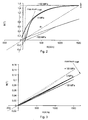
- Figure 5 shows the linearity deviation as a function of shear stresses applied to the load-carrying member for three different types of layer.
- the curve 20 is the output signal for a plated Ni-Fe layer, with 40% Fe, which is not heat-treated.
- the curve 22 is the output signal for a plated and heat-treated Ni-Fe layer, with 50% Fe
- the curve 24 is the output signal for a plated Ni layer, without Fe and not heat-treated.
- the linearity deviation is smallest for the heat-treated Ni-Fe layer.
- the measuring layer produced by the inventive method, is linear over a large load range, it is suitable for measure torques in a large load range.
- the invention makes it possible to produce a torque sensor that can measure shear stresses with high accuracy up to 300MPa.
- the present invention is not limited to the embodiments disclosed but may be varied and modified within the scope of the following claims.
- the inventive layer without undergoing a crystallization process of a nanocrystalline layer, instead the layer can be directly formed with the desired grain size and magnetic properties, for example, by means of metal spraying.
Landscapes
- Physics & Mathematics (AREA)
- Electromagnetism (AREA)
- General Physics & Mathematics (AREA)
- Engineering & Computer Science (AREA)
- Manufacturing & Machinery (AREA)
- Electroplating Methods And Accessories (AREA)
- Heat Treatment Of Articles (AREA)
- Investigating Or Analyzing Materials By The Use Of Magnetic Means (AREA)
Claims (22)
- Verfahren zum Herstellen einer Schicht (3) auf einem Lastaufnahmeelement (1), wobei die Schicht zum Messen von Spannungen vorgesehen ist, die durch eine Kraft induziert werden, welche auf das Lastaufnahmeelement ausgeübt wird, wobei das Verfahren Folgendes umfasst:Bilden einer nanokristallinen Schicht aus einer magnetoelastischen Legierung, die eine durchschnittliche Korngröße von weniger als 50 nm hat, auf einer Fläche des Elementes, undWärmebehandeln der Schicht, bis eine Kristallisierung der Legierung auftritt und die durchschnittliche Korngröße im Bereich von 100 nm bis 10.000 nm liegt.
- Verfahren nach Anspruch 1, wobei die durchschnittliche Korngröße der Schicht im Bereich von 100 nm bis 5000 nm, vorzugsweise von 100 nm bis 1.000 nm, am meisten bevorzugt von 200 nm bis 500 nm liegt.
- Verfahren nach Anspruch 1 oder 2, wobei die Schicht bis auf eine Temperatur von mehr als 300 °C, aber unterhalb des Schmelzpunktes der Schicht wärmebehandelt wird, vorzugsweise bis zu einer Temperatur im Bereich von 350 °C bis 1000 °C, am meisten bevorzugt bis zu einer Temperatur von 400 °C bis 800 °C.
- Verfahren nach einem der Ansprüche 1-3, wobei die Legierung Eisen im Bereich von 23-65 Gew-%, vorzugsweise 30-60 Gew-% und am meisten bevorzugt 35-55 Gew-% umfasst.
- Verfahren nach Anspruch 4, wobei die Legierung Nickel im Bereich von 35-77 Gew-%, vorzugsweise 40-70 Gew-% und am meisten bevorzugt 45-65 Gew-% umfasst.
- Verfahren nach Anspruch 4 oder 5, wobei die Legierung weniger als 10 Gew-% von einem oder mehreren anderen Legierungselementen umfasst.
- Verfahren nach einem der vorherigen Ansprüche, wobei die Schicht wärmebehandelt wird, bis eine Kristallisation der Legierung auftritt und die relative Permeabilität (µr) kleiner als 500 wird und die maximale differenzielle Permeabilität (µdiff) kleiner als die zweifache relative Permeabilität wird, beide in einem Magnetfeld mit einer Amplitude von weniger als 1500 A/m gemessen.
- Verfahren nach einem der vorherigen Ansprüche, wobei die Wärmebehandlung mittels Induktionsheizung vorgenommen wird.
- Verfahren nach einem der vorherigen Ansprüche, wobei die Schicht auf dem Element mittels galvanischer Beschichtung gebildet wird.
- Verfahren nach einem der vorherigen Ansprüche, wobei die Schicht über eine Zeitdauer von weniger als 30 Sekunden wärmebehandelt wird.
- Verfahren nach einem der vorherigen Ansprüche, wobei die Schicht zum Messen von Spannungen bestimmt ist, die durch ein Drehmoment induziert werden, welches auf das Lastaufnahmeelement ausgeübt wird.
- Messvorrichtung, die eine Schicht (3) einer magnetoelastischen Legierung umfasst, welche auf einem Lastaufnahmeelement (1) gebildet ist, wobei die Schicht zum Messen von Spannungen bestimmt ist, die durch eine Kraft induziert werden, welche auf das Lastaufnahmeelement ausgeübt wird, dadurch gekennzeichnet, dass die durchschnittliche Korngröße der Schicht im Bereich von 200 nm bis 10.000 nm liegt.
- Vorrichtung nach Anspruch 12, wobei die durchschnittliche Korngröße der Schicht im Bereich von 200 nm bis 5.000 nm, vorzugsweise von 200 nm bis 1.000 nm, am meisten bevorzugt von 200 nm bis 500 nm liegt.
- Vorrichtung nach Anspruch 12 oder 13, wobei die Legierung Eisen im Bereich von 23-65 Gew-%, vorzugsweise 30-60 Gew-% und am meisten bevorzugt 35-55 Gew-% umfasst.
- Vorrichtung nach Anspruch 14, wobei die Legierung Nickel im Bereich von 35-77 Gew-%, vorzugsweise 40-70 Gew-% und am meisten bevorzugt 45-65 Gew-% umfasst.
- Vorrichtung nach Anspruch 14 oder 15, wobei die Legierung weniger als 10 Gew-% von anderen Legierungselementen umfasst.
- Vorrichtung nach einem der Ansprüche 12-16, wobei die relative Permeabilität (µr) kleiner als 500 und die maximale differenzielle Permeabilität (µdiff) kleiner als zweimal die relative Permeabilität ist, beide in einem Magnetisierungsfeld mit einer Amplitude von kleiner als 1500 A/m gemessen.
- Vorrichtung nach einem der Ansprüche 12-17, wobei die stressmessende Schicht durch Bilden einer nanokristallinen Schicht aus einer magnetoelastischen Legierung, die eine durchschnittliche Korngröße von weniger als 50 nm auf einer Fläche des Lastaufnahmeelementes hat, und durch Wärmebehandeln der Schicht bis zu einer Temperatur von mehr als 300 °C, aber weniger als dem Schmelzpunkt der Schicht erhalten wird, bis ein Kristallisieren der Legierung auftritt.
- Vorrichtung nach einem der Ansprüche 12-18, wobei die Messvorrichtung ein Drehmomentsensor ist.
- Vorrichtung nach einem der Ansprüche 12-18, wobei die Messvorrichtung ein Kraftsensor ist.
- Verwendung des Verfahrens nach einem der Ansprüche 1-11 zum Herstellen eines Drehmomentsensors.
- Verwendung des Verfahrens nach einem der Ansprüche 1-11 zum Herstellen eines Kraftsensors.
Applications Claiming Priority (2)
| Application Number | Priority Date | Filing Date | Title |
|---|---|---|---|
| SE0600543A SE529789C8 (sv) | 2006-03-10 | 2006-03-10 | Mätanordning omfattande ett skikt av en magnetoelastisk legering och förfarande för tillverkning av mätanordningen |
| PCT/SE2007/050088 WO2007106024A1 (en) | 2006-03-10 | 2007-02-14 | A measuring device including a layer of a magnetoelastic alloy and a method for production thereof |
Publications (3)
| Publication Number | Publication Date |
|---|---|
| EP2018530A1 EP2018530A1 (de) | 2009-01-28 |
| EP2018530A4 EP2018530A4 (de) | 2011-06-29 |
| EP2018530B1 true EP2018530B1 (de) | 2013-06-19 |
Family
ID=38509762
Family Applications (1)
| Application Number | Title | Priority Date | Filing Date |
|---|---|---|---|
| EP07709481.1A Not-in-force EP2018530B1 (de) | 2006-03-10 | 2007-02-14 | Messvorrichtung mit einer magnetoelastischen legierungsschicht und herstellungsverfahren |
Country Status (6)
| Country | Link |
|---|---|
| US (1) | US8316724B2 (de) |
| EP (1) | EP2018530B1 (de) |
| JP (1) | JP4931992B2 (de) |
| CN (1) | CN101416036B (de) |
| SE (1) | SE529789C8 (de) |
| WO (1) | WO2007106024A1 (de) |
Families Citing this family (11)
| Publication number | Priority date | Publication date | Assignee | Title |
|---|---|---|---|---|
| EP2169371B1 (de) | 2008-09-25 | 2011-11-09 | Abb Ab | Sensor zum Messen von mechanischen Belastungen mit einer Schicht aus magnetoelastischem Material |
| CN103439034B (zh) * | 2013-09-09 | 2015-05-13 | 淮海工学院 | 一种多功能测力传感器 |
| DE102015202240B3 (de) * | 2015-02-09 | 2016-02-25 | Schaeffler Technologies AG & Co. KG | Anordnung zur Messung einer Kraft oder eines Momentes mit mindestens drei Magnetfeldsensoren |
| WO2017057750A1 (ja) * | 2015-10-01 | 2017-04-06 | ヤマハ発動機株式会社 | 磁歪式センサ |
| CN105466998B (zh) * | 2015-12-31 | 2018-11-06 | 爱德森(厦门)电子有限公司 | 一种利用变频变磁场激励测试铁磁材料硬度特性的方法 |
| US20190178683A1 (en) | 2016-05-17 | 2019-06-13 | Kongsberg Inc. | System, Method And Object For High Accuracy Magnetic Position Sensing |
| US11486776B2 (en) | 2016-12-12 | 2022-11-01 | Kongsberg Inc. | Dual-band magnetoelastic torque sensor |
| JP2021527825A (ja) * | 2018-06-21 | 2021-10-14 | トラファグ アクツィエンゲゼルシャフトTrafag Ag | 負荷測定装備、この製造方法、及びこれでもって実行可能な負荷測定方法 |
| DE102019005859A1 (de) * | 2019-08-20 | 2021-02-25 | Methode Electronics Malta Ltd. | Verfahren zur Messung eines auf einen magnetoelastischen Körper aufgebrachten Drehmoments |
| MX2022002951A (es) | 2019-09-13 | 2022-05-10 | Ka Group Ag | Ensamble de sensor magnetoelástico de par torsiónal para reducir el error magnético debido a armónicos. |
| US12281951B2 (en) | 2020-02-11 | 2025-04-22 | Brp Megatech Industries Inc. | Magnetoelastic torque sensor with local measurement of ambient magnetic field |
Family Cites Families (15)
| Publication number | Priority date | Publication date | Assignee | Title |
|---|---|---|---|---|
| US4896544A (en) * | 1986-12-05 | 1990-01-30 | Mag Dev Inc. | Magnetoelastic torque transducer |
| KR910002375B1 (ko) * | 1987-07-14 | 1991-04-20 | 히다찌 긴조꾸 가부시끼가이샤 | 자성코어 및 그 제조방법 |
| DE3814348A1 (de) * | 1988-04-28 | 1989-11-09 | Philips Patentverwaltung | Verfahren zur herstellung einer polykristallinen halbleitenden widerstandsschicht aus silicium auf einem siliciumtraeger |
| US5142227A (en) * | 1990-06-04 | 1992-08-25 | Allied-Signal Inc. | Method and apparatus for measuring strain within a ferromagnetic material by sensing change in coercive field |
| US5324571A (en) * | 1992-02-05 | 1994-06-28 | Konica Corporation | Magnetic recording medium comprising a support and a plurality of layers in which the magnetic layer has a specified plastic deformation |
| DE4220226A1 (de) * | 1992-06-20 | 1993-12-23 | Bosch Gmbh Robert | Magnetostrikiver Wandler |
| US5585574A (en) * | 1993-02-02 | 1996-12-17 | Mitsubishi Materials Corporation | Shaft having a magnetostrictive torque sensor and a method for making same |
| JPH0815060A (ja) * | 1994-06-28 | 1996-01-19 | Mitsubishi Materials Corp | トルクセンサ用磁歪膜およびその製造方法 |
| CN1256796A (zh) * | 1998-03-05 | 2000-06-14 | 皇家菲利浦电子有限公司 | 磁致伸缩应力传感器 |
| JPH11258077A (ja) * | 1998-03-10 | 1999-09-24 | Toyota Autom Loom Works Ltd | トルクセンサ |
| US6258185B1 (en) * | 1999-05-25 | 2001-07-10 | Bechtel Bwxt Idaho, Llc | Methods of forming steel |
| JP4337209B2 (ja) * | 2000-02-22 | 2009-09-30 | 日立金属株式会社 | 永久磁石薄膜およびその製造方法 |
| JP2002107241A (ja) * | 2000-09-28 | 2002-04-10 | Hitachi Metals Ltd | トルク伝達軸およびそれを用いたトルクセンサ |
| GB0107182D0 (en) * | 2001-03-22 | 2001-05-09 | Secr Defence | Stress sensor |
| WO2004106565A2 (en) * | 2003-05-23 | 2004-12-09 | The Nanosteel Company | Layered metallic material formed from iron based glass alloys |
-
2006
- 2006-03-10 SE SE0600543A patent/SE529789C8/sv not_active IP Right Cessation
-
2007
- 2007-02-14 EP EP07709481.1A patent/EP2018530B1/de not_active Not-in-force
- 2007-02-14 CN CN200780008135.0A patent/CN101416036B/zh not_active Expired - Fee Related
- 2007-02-14 US US12/282,352 patent/US8316724B2/en active Active
- 2007-02-14 WO PCT/SE2007/050088 patent/WO2007106024A1/en not_active Ceased
- 2007-02-14 JP JP2009500328A patent/JP4931992B2/ja not_active Expired - Fee Related
Also Published As
| Publication number | Publication date |
|---|---|
| JP2009529692A (ja) | 2009-08-20 |
| EP2018530A4 (de) | 2011-06-29 |
| SE0600543L (sv) | 2007-09-11 |
| CN101416036A (zh) | 2009-04-22 |
| JP4931992B2 (ja) | 2012-05-16 |
| SE529789C8 (sv) | 2007-12-27 |
| EP2018530A1 (de) | 2009-01-28 |
| US20090249893A1 (en) | 2009-10-08 |
| SE529789C2 (sv) | 2007-11-27 |
| CN101416036B (zh) | 2010-12-01 |
| US8316724B2 (en) | 2012-11-27 |
| WO2007106024A1 (en) | 2007-09-20 |
Similar Documents
| Publication | Publication Date | Title |
|---|---|---|
| EP2018530B1 (de) | Messvorrichtung mit einer magnetoelastischen legierungsschicht und herstellungsverfahren | |
| JP3164590B2 (ja) | 二相シャフトを有するカラーのない円周方向磁化トルク変換器及びそれを用いたトルク測定方法 | |
| Remy et al. | Twinning and strain-induced fcc→ hcp transformation on the mechanical properties of Co Ni Cr Mo alloys | |
| JP5215855B2 (ja) | Fe基合金及びその製造方法 | |
| JPS63252487A (ja) | 磁気弾性トルク・トランスデューサ | |
| Baker et al. | The effect of temperature and Fe: Al ratio on the flow and fracture of FeAl | |
| Kato et al. | Cyclic stress–strain response of superelastic Cu–Al–Mn alloy single crystals | |
| US8272277B2 (en) | Sensor for measuring stresses including a layer of a magnetoelastic material and a method for producing the layer | |
| JP2004037240A (ja) | 磁歪式トルクセンサシャフトおよびその製造方法 | |
| Koyama et al. | Si content dependence on shape memory and tensile properties in Fe–Mn–Si–C alloys | |
| Lee et al. | High temperature microstructural evolution of 304L stainless steel as function of pre-strain and strain rate | |
| Nakajima et al. | Performance boost of co-rich fe-co based alloy magnetostrictive sensors via nitrogen treatment | |
| Nielsen | Separation into two contributions of stress anneal induced magnetic anistropy in metallis glass ribbons | |
| Yamaura | Microstructure and magnetostriction of heavily groove-rolled Fe-Co alloy wires | |
| Huang et al. | Dynamic impact behavior and ferrite variation of special stainless steels | |
| Okamoto et al. | Magnetocrystalline anisotropy constant and twinning stress in martensite phase of Ni–Mn–Ga | |
| EP3894817B1 (de) | Sensorvorrichtung und verfahren zur bestimmung eines drehmoments einer drehmoment-übertragungseinrichtung | |
| JP3024817B2 (ja) | 磁歪式トルクセンサ用磁歪検出体及びその製造方法 | |
| JPH1137864A (ja) | 磁歪式トルクセンサの磁歪膜の製造方法 | |
| Schurter et al. | Elastic properties and auxetic behavior of Galfenol for a range of compositions | |
| JPH10260093A (ja) | 磁歪式トルクセンサの磁歪膜の製造方法 | |
| JP5648958B2 (ja) | 磁歪力センサ用板状部材の製造方法、磁歪力センサ用リング状部材及び磁歪力センサ用リング状部材の製造方法 | |
| Morrison et al. | Cyclic plasticity of polycrystalline nickel at low plastic strain amplitude: constricted hysteresis loops | |
| Saito et al. | Magnetostriction of polycrystalline strong-textured Fe-17at% Ga alloy fabricated by combining rapid-solidification and sintering processes | |
| AMORPHOUS et al. | B. Hernandoa), J. Olivera, ML Sánchez, VM Prida, MJ Pérez, JD Santos and P. Gorria |
Legal Events
| Date | Code | Title | Description |
|---|---|---|---|
| PUAI | Public reference made under article 153(3) epc to a published international application that has entered the european phase |
Free format text: ORIGINAL CODE: 0009012 |
|
| 17P | Request for examination filed |
Effective date: 20080729 |
|
| AK | Designated contracting states |
Kind code of ref document: A1 Designated state(s): AT BE BG CH CY CZ DE DK EE ES FI FR GB GR HU IE IS IT LI LT LU LV MC NL PL PT RO SE SI SK TR |
|
| AX | Request for extension of the european patent |
Extension state: AL BA HR MK RS |
|
| A4 | Supplementary search report drawn up and despatched |
Effective date: 20110531 |
|
| DAX | Request for extension of the european patent (deleted) | ||
| 17Q | First examination report despatched |
Effective date: 20120913 |
|
| RIC1 | Information provided on ipc code assigned before grant |
Ipc: H01L 41/12 20060101ALI20121011BHEP Ipc: G01L 3/10 20060101AFI20121011BHEP Ipc: H01L 41/22 20060101ALI20121011BHEP |
|
| GRAP | Despatch of communication of intention to grant a patent |
Free format text: ORIGINAL CODE: EPIDOSNIGR1 |
|
| GRAS | Grant fee paid |
Free format text: ORIGINAL CODE: EPIDOSNIGR3 |
|
| GRAA | (expected) grant |
Free format text: ORIGINAL CODE: 0009210 |
|
| AK | Designated contracting states |
Kind code of ref document: B1 Designated state(s): AT BE BG CH CY CZ DE DK EE ES FI FR GB GR HU IE IS IT LI LT LU LV MC NL PL PT RO SE SI SK TR |
|
| REG | Reference to a national code |
Ref country code: GB Ref legal event code: FG4D |
|
| REG | Reference to a national code |
Ref country code: CH Ref legal event code: EP |
|
| REG | Reference to a national code |
Ref country code: AT Ref legal event code: REF Ref document number: 617906 Country of ref document: AT Kind code of ref document: T Effective date: 20130715 |
|
| REG | Reference to a national code |
Ref country code: IE Ref legal event code: FG4D |
|
| REG | Reference to a national code |
Ref country code: DE Ref legal event code: R096 Ref document number: 602007031112 Country of ref document: DE Effective date: 20130814 |
|
| PG25 | Lapsed in a contracting state [announced via postgrant information from national office to epo] |
Ref country code: SE Free format text: LAPSE BECAUSE OF FAILURE TO SUBMIT A TRANSLATION OF THE DESCRIPTION OR TO PAY THE FEE WITHIN THE PRESCRIBED TIME-LIMIT Effective date: 20130619 Ref country code: ES Free format text: LAPSE BECAUSE OF FAILURE TO SUBMIT A TRANSLATION OF THE DESCRIPTION OR TO PAY THE FEE WITHIN THE PRESCRIBED TIME-LIMIT Effective date: 20130930 Ref country code: SI Free format text: LAPSE BECAUSE OF FAILURE TO SUBMIT A TRANSLATION OF THE DESCRIPTION OR TO PAY THE FEE WITHIN THE PRESCRIBED TIME-LIMIT Effective date: 20130619 Ref country code: LT Free format text: LAPSE BECAUSE OF FAILURE TO SUBMIT A TRANSLATION OF THE DESCRIPTION OR TO PAY THE FEE WITHIN THE PRESCRIBED TIME-LIMIT Effective date: 20130619 Ref country code: GR Free format text: LAPSE BECAUSE OF FAILURE TO SUBMIT A TRANSLATION OF THE DESCRIPTION OR TO PAY THE FEE WITHIN THE PRESCRIBED TIME-LIMIT Effective date: 20130920 Ref country code: FI Free format text: LAPSE BECAUSE OF FAILURE TO SUBMIT A TRANSLATION OF THE DESCRIPTION OR TO PAY THE FEE WITHIN THE PRESCRIBED TIME-LIMIT Effective date: 20130619 |
|
| REG | Reference to a national code |
Ref country code: LT Ref legal event code: MG4D |
|
| PG25 | Lapsed in a contracting state [announced via postgrant information from national office to epo] |
Ref country code: BG Free format text: LAPSE BECAUSE OF FAILURE TO SUBMIT A TRANSLATION OF THE DESCRIPTION OR TO PAY THE FEE WITHIN THE PRESCRIBED TIME-LIMIT Effective date: 20130919 |
|
| REG | Reference to a national code |
Ref country code: NL Ref legal event code: VDEP Effective date: 20130619 |
|
| PG25 | Lapsed in a contracting state [announced via postgrant information from national office to epo] |
Ref country code: LV Free format text: LAPSE BECAUSE OF FAILURE TO SUBMIT A TRANSLATION OF THE DESCRIPTION OR TO PAY THE FEE WITHIN THE PRESCRIBED TIME-LIMIT Effective date: 20130619 |
|
| PG25 | Lapsed in a contracting state [announced via postgrant information from national office to epo] |
Ref country code: IS Free format text: LAPSE BECAUSE OF FAILURE TO SUBMIT A TRANSLATION OF THE DESCRIPTION OR TO PAY THE FEE WITHIN THE PRESCRIBED TIME-LIMIT Effective date: 20131019 Ref country code: CY Free format text: LAPSE BECAUSE OF FAILURE TO SUBMIT A TRANSLATION OF THE DESCRIPTION OR TO PAY THE FEE WITHIN THE PRESCRIBED TIME-LIMIT Effective date: 20130724 Ref country code: EE Free format text: LAPSE BECAUSE OF FAILURE TO SUBMIT A TRANSLATION OF THE DESCRIPTION OR TO PAY THE FEE WITHIN THE PRESCRIBED TIME-LIMIT Effective date: 20130619 Ref country code: BE Free format text: LAPSE BECAUSE OF FAILURE TO SUBMIT A TRANSLATION OF THE DESCRIPTION OR TO PAY THE FEE WITHIN THE PRESCRIBED TIME-LIMIT Effective date: 20130619 Ref country code: PT Free format text: LAPSE BECAUSE OF FAILURE TO SUBMIT A TRANSLATION OF THE DESCRIPTION OR TO PAY THE FEE WITHIN THE PRESCRIBED TIME-LIMIT Effective date: 20131021 Ref country code: SK Free format text: LAPSE BECAUSE OF FAILURE TO SUBMIT A TRANSLATION OF THE DESCRIPTION OR TO PAY THE FEE WITHIN THE PRESCRIBED TIME-LIMIT Effective date: 20130619 Ref country code: CZ Free format text: LAPSE BECAUSE OF FAILURE TO SUBMIT A TRANSLATION OF THE DESCRIPTION OR TO PAY THE FEE WITHIN THE PRESCRIBED TIME-LIMIT Effective date: 20130619 |
|
| PG25 | Lapsed in a contracting state [announced via postgrant information from national office to epo] |
Ref country code: NL Free format text: LAPSE BECAUSE OF FAILURE TO SUBMIT A TRANSLATION OF THE DESCRIPTION OR TO PAY THE FEE WITHIN THE PRESCRIBED TIME-LIMIT Effective date: 20130619 Ref country code: RO Free format text: LAPSE BECAUSE OF FAILURE TO SUBMIT A TRANSLATION OF THE DESCRIPTION OR TO PAY THE FEE WITHIN THE PRESCRIBED TIME-LIMIT Effective date: 20130619 Ref country code: PL Free format text: LAPSE BECAUSE OF FAILURE TO SUBMIT A TRANSLATION OF THE DESCRIPTION OR TO PAY THE FEE WITHIN THE PRESCRIBED TIME-LIMIT Effective date: 20130619 |
|
| PG25 | Lapsed in a contracting state [announced via postgrant information from national office to epo] |
Ref country code: CY Free format text: LAPSE BECAUSE OF FAILURE TO SUBMIT A TRANSLATION OF THE DESCRIPTION OR TO PAY THE FEE WITHIN THE PRESCRIBED TIME-LIMIT Effective date: 20130619 |
|
| PLBE | No opposition filed within time limit |
Free format text: ORIGINAL CODE: 0009261 |
|
| STAA | Information on the status of an ep patent application or granted ep patent |
Free format text: STATUS: NO OPPOSITION FILED WITHIN TIME LIMIT |
|
| PG25 | Lapsed in a contracting state [announced via postgrant information from national office to epo] |
Ref country code: DK Free format text: LAPSE BECAUSE OF FAILURE TO SUBMIT A TRANSLATION OF THE DESCRIPTION OR TO PAY THE FEE WITHIN THE PRESCRIBED TIME-LIMIT Effective date: 20130619 |
|
| 26N | No opposition filed |
Effective date: 20140320 |
|
| REG | Reference to a national code |
Ref country code: DE Ref legal event code: R097 Ref document number: 602007031112 Country of ref document: DE Effective date: 20140320 |
|
| PG25 | Lapsed in a contracting state [announced via postgrant information from national office to epo] |
Ref country code: LU Free format text: LAPSE BECAUSE OF FAILURE TO SUBMIT A TRANSLATION OF THE DESCRIPTION OR TO PAY THE FEE WITHIN THE PRESCRIBED TIME-LIMIT Effective date: 20140214 Ref country code: MC Free format text: LAPSE BECAUSE OF FAILURE TO SUBMIT A TRANSLATION OF THE DESCRIPTION OR TO PAY THE FEE WITHIN THE PRESCRIBED TIME-LIMIT Effective date: 20130619 |
|
| REG | Reference to a national code |
Ref country code: CH Ref legal event code: PL |
|
| GBPC | Gb: european patent ceased through non-payment of renewal fee |
Effective date: 20140214 |
|
| PG25 | Lapsed in a contracting state [announced via postgrant information from national office to epo] |
Ref country code: CH Free format text: LAPSE BECAUSE OF NON-PAYMENT OF DUE FEES Effective date: 20140228 Ref country code: LI Free format text: LAPSE BECAUSE OF NON-PAYMENT OF DUE FEES Effective date: 20140228 |
|
| REG | Reference to a national code |
Ref country code: IE Ref legal event code: MM4A |
|
| PG25 | Lapsed in a contracting state [announced via postgrant information from national office to epo] |
Ref country code: GB Free format text: LAPSE BECAUSE OF NON-PAYMENT OF DUE FEES Effective date: 20140214 Ref country code: IE Free format text: LAPSE BECAUSE OF NON-PAYMENT OF DUE FEES Effective date: 20140214 |
|
| REG | Reference to a national code |
Ref country code: FR Ref legal event code: PLFP Year of fee payment: 10 |
|
| PG25 | Lapsed in a contracting state [announced via postgrant information from national office to epo] |
Ref country code: HU Free format text: LAPSE BECAUSE OF FAILURE TO SUBMIT A TRANSLATION OF THE DESCRIPTION OR TO PAY THE FEE WITHIN THE PRESCRIBED TIME-LIMIT; INVALID AB INITIO Effective date: 20070214 |
|
| REG | Reference to a national code |
Ref country code: FR Ref legal event code: PLFP Year of fee payment: 11 |
|
| REG | Reference to a national code |
Ref country code: FR Ref legal event code: PLFP Year of fee payment: 12 |
|
| REG | Reference to a national code |
Ref country code: DE Ref legal event code: R081 Ref document number: 602007031112 Country of ref document: DE Owner name: ABB SCHWEIZ AG, CH Free format text: FORMER OWNER: ABB AB, VAESTERAS, SE |
|
| REG | Reference to a national code |
Ref country code: AT Ref legal event code: PC Ref document number: 617906 Country of ref document: AT Kind code of ref document: T Owner name: ABB SCHWEIZ AG, CH Effective date: 20180507 |
|
| REG | Reference to a national code |
Ref country code: FR Ref legal event code: TP Owner name: ABB SCHWEIZ AG, CH Effective date: 20181106 |
|
| PGFP | Annual fee paid to national office [announced via postgrant information from national office to epo] |
Ref country code: AT Payment date: 20200220 Year of fee payment: 14 |
|
| PGFP | Annual fee paid to national office [announced via postgrant information from national office to epo] |
Ref country code: TR Payment date: 20200213 Year of fee payment: 14 Ref country code: FR Payment date: 20200219 Year of fee payment: 14 |
|
| REG | Reference to a national code |
Ref country code: AT Ref legal event code: MM01 Ref document number: 617906 Country of ref document: AT Kind code of ref document: T Effective date: 20210214 |
|
| PG25 | Lapsed in a contracting state [announced via postgrant information from national office to epo] |
Ref country code: AT Free format text: LAPSE BECAUSE OF NON-PAYMENT OF DUE FEES Effective date: 20210214 |
|
| PG25 | Lapsed in a contracting state [announced via postgrant information from national office to epo] |
Ref country code: FR Free format text: LAPSE BECAUSE OF NON-PAYMENT OF DUE FEES Effective date: 20210228 |
|
| PGFP | Annual fee paid to national office [announced via postgrant information from national office to epo] |
Ref country code: DE Payment date: 20240219 Year of fee payment: 18 |
|
| PGFP | Annual fee paid to national office [announced via postgrant information from national office to epo] |
Ref country code: IT Payment date: 20240228 Year of fee payment: 18 |
|
| PG25 | Lapsed in a contracting state [announced via postgrant information from national office to epo] |
Ref country code: TR Free format text: LAPSE BECAUSE OF NON-PAYMENT OF DUE FEES Effective date: 20210214 |
|
| REG | Reference to a national code |
Ref country code: DE Ref legal event code: R119 Ref document number: 602007031112 Country of ref document: DE |
|
| PG25 | Lapsed in a contracting state [announced via postgrant information from national office to epo] |
Ref country code: DE Free format text: LAPSE BECAUSE OF NON-PAYMENT OF DUE FEES Effective date: 20250902 |
|
| PG25 | Lapsed in a contracting state [announced via postgrant information from national office to epo] |
Ref country code: IT Free format text: LAPSE BECAUSE OF NON-PAYMENT OF DUE FEES Effective date: 20250214 |