EP2018318B1 - Strebe zur sicherung einer beweglichen komponente eines flugzeugs - Google Patents
Strebe zur sicherung einer beweglichen komponente eines flugzeugs Download PDFInfo
- Publication number
- EP2018318B1 EP2018318B1 EP07766019.9A EP07766019A EP2018318B1 EP 2018318 B1 EP2018318 B1 EP 2018318B1 EP 07766019 A EP07766019 A EP 07766019A EP 2018318 B1 EP2018318 B1 EP 2018318B1
- Authority
- EP
- European Patent Office
- Prior art keywords
- locking device
- aircraft
- antenna
- locking
- reading
- Prior art date
- Legal status (The legal status is an assumption and is not a legal conclusion. Google has not performed a legal analysis and makes no representation as to the accuracy of the status listed.)
- Active
Links
Images

Classifications
-
- B—PERFORMING OPERATIONS; TRANSPORTING
- B64—AIRCRAFT; AVIATION; COSMONAUTICS
- B64C—AEROPLANES; HELICOPTERS
- B64C25/00—Alighting gear
- B64C25/02—Undercarriages
- B64C25/08—Undercarriages non-fixed, e.g. jettisonable
- B64C25/10—Undercarriages non-fixed, e.g. jettisonable retractable, foldable, or the like
- B64C25/18—Operating mechanisms
- B64C25/26—Control or locking systems therefor
-
- Y—GENERAL TAGGING OF NEW TECHNOLOGICAL DEVELOPMENTS; GENERAL TAGGING OF CROSS-SECTIONAL TECHNOLOGIES SPANNING OVER SEVERAL SECTIONS OF THE IPC; TECHNICAL SUBJECTS COVERED BY FORMER USPC CROSS-REFERENCE ART COLLECTIONS [XRACs] AND DIGESTS
- Y10—TECHNICAL SUBJECTS COVERED BY FORMER USPC
- Y10T—TECHNICAL SUBJECTS COVERED BY FORMER US CLASSIFICATION
- Y10T70/00—Locks
- Y10T70/50—Special application
- Y10T70/5611—For control and machine elements
- Y10T70/5642—Rod
-
- Y—GENERAL TAGGING OF NEW TECHNOLOGICAL DEVELOPMENTS; GENERAL TAGGING OF CROSS-SECTIONAL TECHNOLOGIES SPANNING OVER SEVERAL SECTIONS OF THE IPC; TECHNICAL SUBJECTS COVERED BY FORMER USPC CROSS-REFERENCE ART COLLECTIONS [XRACs] AND DIGESTS
- Y10—TECHNICAL SUBJECTS COVERED BY FORMER USPC
- Y10T—TECHNICAL SUBJECTS COVERED BY FORMER US CLASSIFICATION
- Y10T70/00—Locks
- Y10T70/50—Special application
- Y10T70/5611—For control and machine elements
- Y10T70/5854—Bolt, nut, stud, stud-cap
- Y10T70/5858—Locked stationary
-
- Y—GENERAL TAGGING OF NEW TECHNOLOGICAL DEVELOPMENTS; GENERAL TAGGING OF CROSS-SECTIONAL TECHNOLOGIES SPANNING OVER SEVERAL SECTIONS OF THE IPC; TECHNICAL SUBJECTS COVERED BY FORMER USPC CROSS-REFERENCE ART COLLECTIONS [XRACs] AND DIGESTS
- Y10—TECHNICAL SUBJECTS COVERED BY FORMER USPC
- Y10T—TECHNICAL SUBJECTS COVERED BY FORMER US CLASSIFICATION
- Y10T70/00—Locks
- Y10T70/80—Parts, attachments, accessories and adjuncts
- Y10T70/8027—Condition indicators
- Y10T70/827—Attention-directing
Definitions
- the present invention relates to the field of devices for locking a mobile element of an aircraft.
- Flags or flames may break off as a result of wear or mishandling, or get stuck in a nearby room under the action of the wind, thus evading the sight of ground personnel.
- the locking devices are sometimes painted in a bright color.
- the paints are rapidly attacked by the phosphorus esters present in most hydraulic fluids, so that the locking devices can remain unnoticed, especially under poor lighting or visibility conditions.
- a first object of the invention is to propose a locking device whose presence is easily and quickly detectable.
- a second object of the invention is to provide a ground locking device that can be detected with a very high reliability.
- a third object of the invention is to provide a system for automatically detecting said locking devices.
- the present invention is defined by a device for locking a mobile element of an aircraft comprising an electronic tag adapted to receive an interrogation signal and to return an identification signal of said device.
- the locking device is in the form of a pin.
- the pin comprises a cylindrical portion having an annular groove in which is mounted an omni-directional antenna.
- the antenna is preferably sealed with an elastomeric layer.
- the locking device is in the form of a collar comprising two shells interconnected by means of a longitudinal hinge.
- At least one of these shells comprises a semicylindrical portion having a substantially semi-annular groove in which is mounted an antenna element.
- the antenna element is preferably sealed with an elastomeric layer.
- the signaling means are advantageously adapted to indicate the location of the locking device on a synoptic representation of the aircraft and / or to emit an audible signal if a locking device has been detected.
- the invention also relates to an aircraft in which is embedded such a detection system.
- the idea underlying the invention is to equip the ground locking devices RFID ( Radio Frequency IDentification ) electronic tags also called “RFID tags” or simply “tags”.
- RFID Radio Frequency IDentification
- an electronic tag comprises an antenna, a non-volatile memory in which identification information is stored, a modulator adapted to modulate, by means of said information, an interrogation signal received by the antenna before re-transmitting the signal. signal thus modulated.
- a power supply circuit utilizing the energy of the interrogation signal is provided to power the modulator.
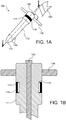
- the Fig. 1A illustrates a locking device according to a first embodiment of the invention. It is in the form of a pin 100 comprising a first cylindrical portion 110 extending at its bottom by a conoidal shape 115 and at its upper part by a second cylindrical portion 117, coaxial with the first but larger diameter.
- the first cylindrical portion is intended to be slidably engaged in a corresponding cavity of the landing gear, for example in an element of the structure unfolding during the exit of the train and / or retracting during its retraction.
- the second cylindrical portion is intended to remain out of said cavity.
- a bar 130 diametrically crosses the pin at its upper end protruding substantially on either side of the second cylindrical portion, so that the extraction and manipulation of the locking pin are facilitated.
- a piston 140 is provided for sliding inside the first and second cylindrical portions in an axial stroke limited by a low stop and a high stop.
- the piston In the rest position, the piston is pressed to the upper stop by a return spring and slightly protrudes from the upper part of the second cylindrical shape.
- the piston radially protrudes two lugs 150 out of the first cylindrical portion. More precisely, these lugs, advantageously steel balls, are spring-mounted and located, diametrically opposite one another, in the lower part of the first cylindrical portion.
- a handling agent wants to lock the landing gear, he pushes the pin into the corresponding cavity.
- the lugs 150 enter their housing when the agent presses the piston 140 to bring it to a low stop or when the pin is pressed into its cavity.
- the pin once in place, the lugs return naturally in the projecting position and lodge in corresponding recesses of the cavity. To clear the pin, simply press the piston 140 which retracts the lugs and allows to remove the pin from its cavity.
- the second cylindrical portion of the locking pin has an annular recess in which the antenna of the electronic tag is mounted.
- the antenna is covered with an elastomer layer 170, preferably chosen in bright color.
- a flag or flame 160 also bright color is advantageously attached (e) to the locking pin by means of a ring, a strap or a resistant wire.
- the Fig. 1B represents the top of the locking pin in an axial section.
- the annular recess 175 in which the antenna 173 is mounted is covered, itself covered with an elastomer ring 170 protecting the antenna in a sealed manner, in particular against corrosion by hydraulic fluids.
- the antenna Since the antenna is housed in the second cylindrical portion, intended to remain outside the cavity, it can transmit and receive without occultation an electromagnetic signal.
- the antenna is advantageously an omnidirectional antenna, partitioned or not in a plurality of sectors.
- the RFID electronic circuit associated with the antenna is also housed in the second cylindrical portion in a cavity (not shown) protected from shocks and mechanical stresses.
- the Fig. 2 represents a locking device according to a second embodiment of the invention. It consists of a collar 200 intended for example to immobilize an escapement cylinder. It comprises two shells 210 hinged about a longitudinal hinge 215. The free ends of the shells can be secured by means of a quick coupling system or a simple bolt-nut system 220. The shells have a substantially semi-cylindrical shape or consist of parts of hemicylindrical shapes to prevent the retraction of the cylinder. A bright flame or flag is also attached to the collar. One or both hemi-cylindrical shells of the collar have a recess at their outer surface, in the form of a half-annular groove, in which the antenna is housed.
- the antenna will comprise two half-annular elements mounted in the respective grooves of the two shells.
- the antenna or the two antenna elements are electrically connected to the RFID electronic circuit, which is itself installed in one of the shells and is protected from shocks and mechanical stresses.
- Each part of the antenna is also covered with an elastomer layer 230 of bright color.
- the locking devices described above can serve to immobilize a moving part of the aircraft when the latter is on the ground, for example a landing gear element or main landing gear.
- the aircraft In order to detect the presence or check the absence of such locking devices, the aircraft is provided with a plurality of antennas distributed on the fuselage, for transmitting an interrogation signal.
- antennas are advantageously antennas conform, that is to say, integrated and of the same shape as the fuselage or mounted on the inner surface of the composite material parts, low electromagnetic absorption, nose and doors of the train of landing of the aircraft.
- the antennas are advantageously arranged so that the locking devices are capable of receiving the direct line interrogation signal or LOS ( Line Of Sight ) .
- the different antennas are coupled to RFID reading devices.
- a reading RFID device When a reading RFID device is instructed to check for the presence of a locking device, it transmits an interrogation signal consisting of a low frequency electromagnetic wave, for example at 125 kHz or at 134.2 kHz.
- the use of a low frequency makes it possible to reduce the phenomena of absorption and diffraction by the metallic structures of the aircraft and to obtain a relatively homogeneous electromagnetic field in the interrogation zone.
- electronic tag reading devices are commonly available at these frequencies.
- a locking device receiving said interrogation signal refers to the reading device a response containing its identification data. These data indicate that the response is sent by a locking device and if necessary provide the type of the device in question.
- the detection of a locking device will be unequivocally associated with the corresponding element of the aircraft.
- the Fig. 3 schematically illustrates an avionics system for detecting the presence or absence of locking devices according to the invention.
- Each reading device 330 is connected to a control and acquisition module 350, itself connected to an avionics communication network 360 obeying an ARINC standard, for example a switched Ethernet network such as an AFDX network ( Avionics Full). Duplex Switched Ethernet ).
- the alarm system 370 can trigger, either automatically or by manual activation, a check of the presence or absence of the locking devices. This verification will be carried out systematically during the pre-takeoff check procedure. It may also be initiated by maintenance personnel to ensure that all locking devices have been properly installed.
- the alarm system 370 transmits to the reading 330 an interrogation command via the control and acquisition modules 350. Alternatively, it can transmit such an order sequentially to the different devices. If a reader device 330 detects a response, it sends back to the alarm system, via its associated control and acquisition module, the identification information of the interlocking device that responded.
- the electronic tags of the locking devices transmit their respective responses with distinct delay times to avoid any collision.
- each label may be equipped with a counter or down timer initialized to a different value and only respond when it expires.
- the alarm system 370 centrally receives the responses of the various modules 350. It can thus determine if a locking device is present and, if necessary, identify it.
- a locking device If a locking device is present, it generates an alarm consisting of an audible signal and / or light indications on a control panel 380 of the cockpit.
- the luminous indications are advantageously carried on a synoptic representation of the aircraft, so that the location of an abnormally present or absent locking device can be immediately located.
- the present invention thus allows the ground crew to remove the locking device before the aircraft leaves the airport.
Landscapes
- Engineering & Computer Science (AREA)
- Mechanical Engineering (AREA)
- Aviation & Aerospace Engineering (AREA)
- Radar Systems Or Details Thereof (AREA)
- Lock And Its Accessories (AREA)
- Support Of Aerials (AREA)
- Transmitters (AREA)
- Details Of Aerials (AREA)
Claims (12)
- Verriegelungsvorrichtung eines beweglichen Elements des Fahrwerks eines Luftfahrzeugs, das vor dem Abflug des Luftfahrzeugs lokalisiert und entfernt werden muss,
dadurch gekennzeichnet, dass sie ein elektronisches Etikett enthält, das geeignet ist, ein Abfragesignal zu empfangen und ein Identifikationssignal der Vorrichtung zurückzusenden. - Verriegelungsvorrichtung nach Anspruch 1, dadurch gekennzeichnet, dass sie in Form eines Stifts (100) vorliegt.
- Verriegelungsvorrichtung nach Anspruch 2, dadurch gekennzeichnet, dass der Stift einen zylindrischen Bereich (117) mit einer Ringnut (175) aufweist, in die eine Rundstrahlantenne (173) montiert ist.
- Verriegelungsvorrichtung nach Anspruch 3, dadurch gekennzeichnet, dass die Antenne dicht mit einer Elastomerschicht (170) bedeckt ist.
- Verriegelungsvorrichtung nach Anspruch 1, dadurch gekennzeichnet, dass sie in Form einer Schelle (200) vorliegt, die zwei Schalen (210) enthält, die miteinander mittels eines Längsscharniers (215) verbunden sind.
- Verriegelungsvorrichtung nach Anspruch 5, dadurch gekennzeichnet, dass mindestens eine Schale einen Bereich von halbzylindrischer Form enthält, der eine im Wesentlichen halbringförmige Nut aufweist, in die ein Antennenelement montiert ist.
- Verriegelungsvorrichtung nach Anspruch 6, dadurch gekennzeichnet, dass das Antennenelement dicht mit einer Elastomerschicht (230) bedeckt ist.
- Erfassungssystem mindestens einer Verriegelungsvorrichtung nach einem der vorhergehenden Ansprüche, dadurch gekennzeichnet, dass es enthält:- Leseeinrichtungen (330) mindestens eines elektronischen Etiketts, um ein Abfragesignal zu übertragen und eine Antwort zu empfangen, die Identifikationsdaten der Vorrichtung enthält;- Steuereinrichtungen (370), die die Leseeinrichtungen steuern und die Identifikationsdaten über ein Avionik-Kommunikationsnetzwerk (360) empfangen; und- Signalisierungseinrichtungen (380), die anzeigen, ob eine Verriegelungsvorrichtung erkannt wurde.
- Erfassungssystem nach Anspruch 8, dadurch gekennzeichnet, dass die Signalisierungseinrichtungen geeignet sind, die Einbaustelle der Verriegelungsvorrichtung in einer synoptischen Darstellung des Luftfahrzeugs anzuzeigen.
- Erfassungssystem nach Anspruch 8 oder 9, dadurch gekennzeichnet, dass die Signalisierungseinrichtungen geeignet sind, ein akustisches Signal zu senden, wenn eine Verriegelungsvorrichtung erfasst wurde.
- Luftfahrzeug, das ein Erfassungssystem nach einem der Ansprüche 8 bis 10 enthält, dadurch gekennzeichnet, dass die Leseeinrichtungen mit mindestens einer Antenne verbunden sind, die auf den inneren Bereich einer Fahrwerktür montiert ist.
- Luftfahrzeug, das ein Erfassungssystem nach einem der Ansprüche 8 bis 10 enthält, dadurch gekennzeichnet, dass die Leseeinrichtungen mit mindestens einer entsprechenden Antenne verbunden sind.
Applications Claiming Priority (2)
| Application Number | Priority Date | Filing Date | Title |
|---|---|---|---|
| FR0651794A FR2901242B1 (fr) | 2006-05-17 | 2006-05-17 | Dispositif de verrouillage d'un element mobile d'un aeronef |
| PCT/FR2007/051239 WO2007132111A1 (fr) | 2006-05-17 | 2007-05-09 | Dispositif de verrouillage d'un élément mobile d'un aéronef |
Publications (2)
| Publication Number | Publication Date |
|---|---|
| EP2018318A1 EP2018318A1 (de) | 2009-01-28 |
| EP2018318B1 true EP2018318B1 (de) | 2018-03-14 |
Family
ID=37103198
Family Applications (1)
| Application Number | Title | Priority Date | Filing Date |
|---|---|---|---|
| EP07766019.9A Active EP2018318B1 (de) | 2006-05-17 | 2007-05-09 | Strebe zur sicherung einer beweglichen komponente eines flugzeugs |
Country Status (9)
| Country | Link |
|---|---|
| US (1) | US8390479B2 (de) |
| EP (1) | EP2018318B1 (de) |
| JP (1) | JP5197580B2 (de) |
| CN (1) | CN101443234B (de) |
| BR (1) | BRPI0712526A2 (de) |
| CA (1) | CA2652561C (de) |
| FR (1) | FR2901242B1 (de) |
| RU (1) | RU2434786C2 (de) |
| WO (1) | WO2007132111A1 (de) |
Families Citing this family (14)
| Publication number | Priority date | Publication date | Assignee | Title |
|---|---|---|---|---|
| US8209351B2 (en) * | 2007-12-18 | 2012-06-26 | Honeywell International Inc. | Display definitions interface for avionics communications systems |
| FR2928761B1 (fr) | 2008-03-17 | 2012-06-01 | Eurocopter France | Appareil a suivi automatise de configuration, procede et systeme pour ce suivi. |
| JP2012502562A (ja) * | 2008-09-03 | 2012-01-26 | スニフ ラブス,インコーポレーテッド | 発見プロトコル |
| GB2466223A (en) * | 2008-12-15 | 2010-06-16 | Robert John Sykes | Aircraft ground lock detection device. |
| RU2442741C2 (ru) * | 2009-12-07 | 2012-02-20 | Николай Николаевич Леухин | Стопорное устройство, система счета, способ его применения (варианты) |
| CN102001445B (zh) * | 2010-11-24 | 2013-01-30 | 南京航空航天大学 | 起落架电磁扭力锁及其控制系统 |
| ES2714311T3 (es) * | 2013-09-04 | 2019-05-28 | Airbus Operations Sl | Método de fabricación de un elemento de aeronave con material auxiliar |
| EP3042849B1 (de) * | 2015-01-12 | 2018-06-13 | Safran Landing Systems UK Limited | Stoppelement einer Flugzeugfahrwerksanordnung |
| US10414510B2 (en) * | 2016-12-30 | 2019-09-17 | Safran Landing Systems Canada Inc. | Landing gear with threadless cardan joint |
| US10479487B2 (en) * | 2017-01-18 | 2019-11-19 | Goodrich Corporation | Landing gear folding brace with locking actuator |
| FR3080880B1 (fr) * | 2018-05-04 | 2020-09-04 | Safran Landing Systems | Dispositif de verrouillage a verrou rotatif a commande impulsionnelle |
| US11919657B2 (en) * | 2020-05-06 | 2024-03-05 | The Boeing Company | Aircraft landing gear monitoring and alerting system and method |
| US12039392B2 (en) * | 2021-01-15 | 2024-07-16 | The Boeing Company | Location of fastener accessory using sacrificial RF tag |
| CN118062227B (zh) * | 2024-01-31 | 2025-08-15 | 长龙(杭州)航空维修工程有限公司 | 一种飞机起落架锁定部件的管控系统、方法及介质 |
Family Cites Families (22)
| Publication number | Priority date | Publication date | Assignee | Title |
|---|---|---|---|---|
| SU1412184A1 (ru) * | 1986-12-26 | 2005-02-20 | А.С. Васильев | Устройство для стопорения штока амортизатора опоры шасси самолета |
| JPS63285448A (ja) * | 1987-05-18 | 1988-11-22 | Mitsubishi Heavy Ind Ltd | 構造体の発生欠陥検知装置 |
| JPH0221498U (de) * | 1988-07-15 | 1990-02-13 | ||
| JPH03118249U (de) * | 1990-03-20 | 1991-12-06 | ||
| DE4029208C2 (de) * | 1990-09-14 | 1995-05-18 | Schulte C E Gmbh | Zylinderschloß mit mechanischer und elektronischer Kodierung |
| US5099226A (en) * | 1991-01-18 | 1992-03-24 | Interamerican Industrial Company | Intelligent security system |
| US5333816A (en) | 1992-09-30 | 1994-08-02 | United Technologies Corporation | Aircraft landing gear swivel locking pin having automatic release and reengage |
| US5860622A (en) * | 1996-10-25 | 1999-01-19 | Weibert; Otis A | Universal aircraft steering by-pass pin |
| JPH11224400A (ja) * | 1998-02-06 | 1999-08-17 | Toshiba Corp | 空港内移動体位置管理システム |
| DE19907654A1 (de) * | 1999-02-23 | 2000-08-24 | Wilka Schliestechnik Gmbh | Schließzylinder mit elektromagnetisch betätigbarem Sperrstift |
| US6714121B1 (en) * | 1999-08-09 | 2004-03-30 | Micron Technology, Inc. | RFID material tracking method and apparatus |
| FR2803935B1 (fr) * | 2000-01-17 | 2002-11-29 | Decaux S A | Systeme automatique de stockage de cycles |
| US6736577B2 (en) * | 2002-05-01 | 2004-05-18 | The Boeing Company | Universal bassinet fittings |
| US7619516B2 (en) * | 2002-10-09 | 2009-11-17 | Seektech, Inc. | Single and multi-trace omnidirectional sonde and line locators and transmitter used therewith |
| EP1450300A1 (de) * | 2003-02-24 | 2004-08-25 | European Community | Vorrichtung zur Versiegelung mit mehreren Transpondern |
| US7270353B2 (en) * | 2003-02-24 | 2007-09-18 | The European Community | Multiple transponder seal device |
| JP2004341653A (ja) * | 2003-05-13 | 2004-12-02 | Nippon Telegr & Teleph Corp <Ntt> | 車両の盗難検出装置、その盗難検出システムおよび盗難検出方法 |
| DE10331440A1 (de) * | 2003-07-10 | 2005-02-17 | Huf Hülsbeck & Fürst Gmbh & Co. Kg | Elektronische Zugangskontrollvorrichtung, sowie Verfahren zur Zugangskontrolle |
| ZA200402317B (en) * | 2003-09-15 | 2004-10-07 | Andrew Gerald Lynn Brown | "A seal". |
| EP1728219A1 (de) * | 2004-03-19 | 2006-12-06 | Roger Marcel Humbel | Alles-schlüssel bzw. einstell software liste in handy (pass-partout) für funk-fahrrad-schlüsser, autos, häuser, rfid-tags mit zulassungs- und zahlungsverkehrs-funktion all in one remote key |
| RU44855U1 (ru) * | 2004-11-23 | 2005-03-27 | Лагутин Юрий Геннадьевич | Система идентификации материальных объектов, маркированный материальный объект и комплект средств маркировки материального объекта |
| US7836973B2 (en) * | 2005-10-20 | 2010-11-23 | Weatherford/Lamb, Inc. | Annulus pressure control drilling systems and methods |
-
2006
- 2006-05-17 FR FR0651794A patent/FR2901242B1/fr not_active Expired - Lifetime
-
2007
- 2007-05-09 WO PCT/FR2007/051239 patent/WO2007132111A1/fr not_active Ceased
- 2007-05-09 CN CN2007800177033A patent/CN101443234B/zh active Active
- 2007-05-09 BR BRPI0712526-7A patent/BRPI0712526A2/pt active Search and Examination
- 2007-05-09 JP JP2009510507A patent/JP5197580B2/ja not_active Expired - Fee Related
- 2007-05-09 EP EP07766019.9A patent/EP2018318B1/de active Active
- 2007-05-09 CA CA2652561A patent/CA2652561C/fr not_active Expired - Fee Related
- 2007-05-09 US US12/299,827 patent/US8390479B2/en not_active Expired - Fee Related
- 2007-05-09 RU RU2008149690A patent/RU2434786C2/ru not_active IP Right Cessation
Also Published As
| Publication number | Publication date |
|---|---|
| EP2018318A1 (de) | 2009-01-28 |
| BRPI0712526A2 (pt) | 2012-09-04 |
| RU2434786C2 (ru) | 2011-11-27 |
| US20090242696A1 (en) | 2009-10-01 |
| CA2652561C (fr) | 2014-11-18 |
| JP2009537375A (ja) | 2009-10-29 |
| CA2652561A1 (fr) | 2007-11-22 |
| RU2008149690A (ru) | 2010-06-27 |
| CN101443234A (zh) | 2009-05-27 |
| CN101443234B (zh) | 2011-02-09 |
| JP5197580B2 (ja) | 2013-05-15 |
| WO2007132111A1 (fr) | 2007-11-22 |
| US8390479B2 (en) | 2013-03-05 |
| FR2901242B1 (fr) | 2009-02-20 |
| FR2901242A1 (fr) | 2007-11-23 |
Similar Documents
| Publication | Publication Date | Title |
|---|---|---|
| CA2652561C (fr) | Dispositif de verrouillage d'un element mobile d'un aeronef | |
| EP2904418B1 (de) | Notfunkbakensystem für flugzeuge oder andere fortbewegungsmittel | |
| EP2993130B1 (de) | Signallicht und herstellungsverfahren | |
| EP2015100B1 (de) | Abnehmbare Notfunkbake für Drehflügler | |
| WO2017098172A1 (fr) | Dispositif volant sans pilote embarqué compatible avec la gestion du trafic aérien | |
| FR2669455A1 (fr) | Installation de teledetection aerienne et/ou terrestre, notamment pour la detection des feux de forets. | |
| EP2995558A1 (de) | Luftfahrzeug, das mindestens einen notsignalsender umfasst | |
| EP3753845B1 (de) | Fahrwerk eines luftfahrzeugs, das mit visuellen alarmanzeigemitteln ausgestattet ist, die zur signalisierung einer winkelüberauslenkung eines ausrichtbaren unteren teils des fahrwerks dienen | |
| FR3007176A1 (fr) | Dispositif, systeme et procede d’escorte pour un aeronef au sol | |
| FR2954560A1 (fr) | Dispositif de securisation de zone de travail | |
| EP3097648B1 (de) | Kommunikationsanordnung in einen flugzeug die den empfang von daten und gps signalen ermöglicht. | |
| WO2011156370A1 (en) | Ground impact cargo parachute release mechanism | |
| EP3176091A2 (de) | System, verfahren und vorrichtung für farbstoff bei suche, rettung und bergung | |
| WO2022263365A1 (fr) | Système embarqué de détection d'impacts sur le fuselage d'un aeronef | |
| EP4538173A1 (de) | Kartuschenauswurfmodul zur lokalisierung verlorener objekte auf see und zugehöriges auswurfsystem | |
| FR3074345A1 (fr) | Dispositif de signalisation d'une situation accidentogene d'un vehicule automobile | |
| EP3464066B1 (de) | Sicherheitsvorrichtung zur überprüfung eines ferngesteuerten flugzeugs | |
| EP0716286A1 (de) | Vorrichtung zum Auffinden von Minen zum Minenräumen | |
| FR3142825A1 (fr) | Méthode pour contrôler à distance le vol d’un aéronef et module de communication associé | |
| WO2022023654A1 (fr) | Plateforme de transport et véhicule pour un transport sécurisé d'objets chargés sur la plateforme, et procédé de chargement ou de déchargement de ladite plateforme | |
| FR2805914A1 (fr) | Systeme electronique de detection a distance des vehicules g.p.l. avec alarme incendie automatique | |
| FR3101330A1 (fr) | Drone pour la localisation de personne recherchée et procédé associé | |
| FR3049317A1 (fr) | Bielle fusible reutilisable | |
| FR3013142A1 (fr) | Enregistreur d'accident flottant pour aeronef |
Legal Events
| Date | Code | Title | Description |
|---|---|---|---|
| PUAI | Public reference made under article 153(3) epc to a published international application that has entered the european phase |
Free format text: ORIGINAL CODE: 0009012 |
|
| 17P | Request for examination filed |
Effective date: 20081107 |
|
| AK | Designated contracting states |
Kind code of ref document: A1 Designated state(s): AT BE BG CH CY CZ DE DK EE ES FI FR GB GR HU IE IS IT LI LT LU LV MC MT NL PL PT RO SE SI SK TR |
|
| AX | Request for extension of the european patent |
Extension state: AL BA HR MK RS |
|
| DAX | Request for extension of the european patent (deleted) | ||
| STAA | Information on the status of an ep patent application or granted ep patent |
Free format text: STATUS: EXAMINATION IS IN PROGRESS |
|
| 17Q | First examination report despatched |
Effective date: 20161207 |
|
| GRAP | Despatch of communication of intention to grant a patent |
Free format text: ORIGINAL CODE: EPIDOSNIGR1 |
|
| STAA | Information on the status of an ep patent application or granted ep patent |
Free format text: STATUS: GRANT OF PATENT IS INTENDED |
|
| INTG | Intention to grant announced |
Effective date: 20170913 |
|
| GRAS | Grant fee paid |
Free format text: ORIGINAL CODE: EPIDOSNIGR3 |
|
| GRAA | (expected) grant |
Free format text: ORIGINAL CODE: 0009210 |
|
| STAA | Information on the status of an ep patent application or granted ep patent |
Free format text: STATUS: THE PATENT HAS BEEN GRANTED |
|
| RAP1 | Party data changed (applicant data changed or rights of an application transferred) |
Owner name: AIRBUS |
|
| AK | Designated contracting states |
Kind code of ref document: B1 Designated state(s): AT BE BG CH CY CZ DE DK EE ES FI FR GB GR HU IE IS IT LI LT LU LV MC MT NL PL PT RO SE SI SK TR |
|
| REG | Reference to a national code |
Ref country code: GB Ref legal event code: FG4D Free format text: NOT ENGLISH |
|
| REG | Reference to a national code |
Ref country code: CH Ref legal event code: EP Ref country code: AT Ref legal event code: REF Ref document number: 978625 Country of ref document: AT Kind code of ref document: T Effective date: 20180315 |
|
| REG | Reference to a national code |
Ref country code: IE Ref legal event code: FG4D Free format text: LANGUAGE OF EP DOCUMENT: FRENCH |
|
| REG | Reference to a national code |
Ref country code: DE Ref legal event code: R096 Ref document number: 602007054224 Country of ref document: DE |
|
| REG | Reference to a national code |
Ref country code: FR Ref legal event code: PLFP Year of fee payment: 12 |
|
| REG | Reference to a national code |
Ref country code: NL Ref legal event code: MP Effective date: 20180314 |
|
| REG | Reference to a national code |
Ref country code: LT Ref legal event code: MG4D |
|
| PG25 | Lapsed in a contracting state [announced via postgrant information from national office to epo] |
Ref country code: FI Free format text: LAPSE BECAUSE OF FAILURE TO SUBMIT A TRANSLATION OF THE DESCRIPTION OR TO PAY THE FEE WITHIN THE PRESCRIBED TIME-LIMIT Effective date: 20180314 Ref country code: CY Free format text: LAPSE BECAUSE OF FAILURE TO SUBMIT A TRANSLATION OF THE DESCRIPTION OR TO PAY THE FEE WITHIN THE PRESCRIBED TIME-LIMIT Effective date: 20180314 Ref country code: ES Free format text: LAPSE BECAUSE OF FAILURE TO SUBMIT A TRANSLATION OF THE DESCRIPTION OR TO PAY THE FEE WITHIN THE PRESCRIBED TIME-LIMIT Effective date: 20180314 Ref country code: LT Free format text: LAPSE BECAUSE OF FAILURE TO SUBMIT A TRANSLATION OF THE DESCRIPTION OR TO PAY THE FEE WITHIN THE PRESCRIBED TIME-LIMIT Effective date: 20180314 |
|
| REG | Reference to a national code |
Ref country code: AT Ref legal event code: MK05 Ref document number: 978625 Country of ref document: AT Kind code of ref document: T Effective date: 20180314 |
|
| PG25 | Lapsed in a contracting state [announced via postgrant information from national office to epo] |
Ref country code: BG Free format text: LAPSE BECAUSE OF FAILURE TO SUBMIT A TRANSLATION OF THE DESCRIPTION OR TO PAY THE FEE WITHIN THE PRESCRIBED TIME-LIMIT Effective date: 20180614 Ref country code: GR Free format text: LAPSE BECAUSE OF FAILURE TO SUBMIT A TRANSLATION OF THE DESCRIPTION OR TO PAY THE FEE WITHIN THE PRESCRIBED TIME-LIMIT Effective date: 20180615 Ref country code: LV Free format text: LAPSE BECAUSE OF FAILURE TO SUBMIT A TRANSLATION OF THE DESCRIPTION OR TO PAY THE FEE WITHIN THE PRESCRIBED TIME-LIMIT Effective date: 20180314 Ref country code: SE Free format text: LAPSE BECAUSE OF FAILURE TO SUBMIT A TRANSLATION OF THE DESCRIPTION OR TO PAY THE FEE WITHIN THE PRESCRIBED TIME-LIMIT Effective date: 20180314 |
|
| PG25 | Lapsed in a contracting state [announced via postgrant information from national office to epo] |
Ref country code: MT Free format text: LAPSE BECAUSE OF FAILURE TO SUBMIT A TRANSLATION OF THE DESCRIPTION OR TO PAY THE FEE WITHIN THE PRESCRIBED TIME-LIMIT Effective date: 20180314 |
|
| PG25 | Lapsed in a contracting state [announced via postgrant information from national office to epo] |
Ref country code: EE Free format text: LAPSE BECAUSE OF FAILURE TO SUBMIT A TRANSLATION OF THE DESCRIPTION OR TO PAY THE FEE WITHIN THE PRESCRIBED TIME-LIMIT Effective date: 20180314 Ref country code: PL Free format text: LAPSE BECAUSE OF FAILURE TO SUBMIT A TRANSLATION OF THE DESCRIPTION OR TO PAY THE FEE WITHIN THE PRESCRIBED TIME-LIMIT Effective date: 20180314 Ref country code: NL Free format text: LAPSE BECAUSE OF FAILURE TO SUBMIT A TRANSLATION OF THE DESCRIPTION OR TO PAY THE FEE WITHIN THE PRESCRIBED TIME-LIMIT Effective date: 20180314 Ref country code: RO Free format text: LAPSE BECAUSE OF FAILURE TO SUBMIT A TRANSLATION OF THE DESCRIPTION OR TO PAY THE FEE WITHIN THE PRESCRIBED TIME-LIMIT Effective date: 20180314 Ref country code: IT Free format text: LAPSE BECAUSE OF FAILURE TO SUBMIT A TRANSLATION OF THE DESCRIPTION OR TO PAY THE FEE WITHIN THE PRESCRIBED TIME-LIMIT Effective date: 20180314 |
|
| PG25 | Lapsed in a contracting state [announced via postgrant information from national office to epo] |
Ref country code: SK Free format text: LAPSE BECAUSE OF FAILURE TO SUBMIT A TRANSLATION OF THE DESCRIPTION OR TO PAY THE FEE WITHIN THE PRESCRIBED TIME-LIMIT Effective date: 20180314 Ref country code: AT Free format text: LAPSE BECAUSE OF FAILURE TO SUBMIT A TRANSLATION OF THE DESCRIPTION OR TO PAY THE FEE WITHIN THE PRESCRIBED TIME-LIMIT Effective date: 20180314 Ref country code: CZ Free format text: LAPSE BECAUSE OF FAILURE TO SUBMIT A TRANSLATION OF THE DESCRIPTION OR TO PAY THE FEE WITHIN THE PRESCRIBED TIME-LIMIT Effective date: 20180314 |
|
| REG | Reference to a national code |
Ref country code: CH Ref legal event code: PL |
|
| REG | Reference to a national code |
Ref country code: DE Ref legal event code: R097 Ref document number: 602007054224 Country of ref document: DE |
|
| PG25 | Lapsed in a contracting state [announced via postgrant information from national office to epo] |
Ref country code: PT Free format text: LAPSE BECAUSE OF FAILURE TO SUBMIT A TRANSLATION OF THE DESCRIPTION OR TO PAY THE FEE WITHIN THE PRESCRIBED TIME-LIMIT Effective date: 20180716 |
|
| PLBE | No opposition filed within time limit |
Free format text: ORIGINAL CODE: 0009261 |
|
| STAA | Information on the status of an ep patent application or granted ep patent |
Free format text: STATUS: NO OPPOSITION FILED WITHIN TIME LIMIT |
|
| REG | Reference to a national code |
Ref country code: BE Ref legal event code: MM Effective date: 20180531 |
|
| PG25 | Lapsed in a contracting state [announced via postgrant information from national office to epo] |
Ref country code: DK Free format text: LAPSE BECAUSE OF FAILURE TO SUBMIT A TRANSLATION OF THE DESCRIPTION OR TO PAY THE FEE WITHIN THE PRESCRIBED TIME-LIMIT Effective date: 20180314 Ref country code: MC Free format text: LAPSE BECAUSE OF FAILURE TO SUBMIT A TRANSLATION OF THE DESCRIPTION OR TO PAY THE FEE WITHIN THE PRESCRIBED TIME-LIMIT Effective date: 20180314 |
|
| 26N | No opposition filed |
Effective date: 20181217 |
|
| REG | Reference to a national code |
Ref country code: IE Ref legal event code: MM4A |
|
| PG25 | Lapsed in a contracting state [announced via postgrant information from national office to epo] |
Ref country code: LI Free format text: LAPSE BECAUSE OF NON-PAYMENT OF DUE FEES Effective date: 20180531 Ref country code: SI Free format text: LAPSE BECAUSE OF FAILURE TO SUBMIT A TRANSLATION OF THE DESCRIPTION OR TO PAY THE FEE WITHIN THE PRESCRIBED TIME-LIMIT Effective date: 20180314 Ref country code: CH Free format text: LAPSE BECAUSE OF NON-PAYMENT OF DUE FEES Effective date: 20180531 |
|
| PG25 | Lapsed in a contracting state [announced via postgrant information from national office to epo] |
Ref country code: LU Free format text: LAPSE BECAUSE OF NON-PAYMENT OF DUE FEES Effective date: 20180509 |
|
| PG25 | Lapsed in a contracting state [announced via postgrant information from national office to epo] |
Ref country code: IE Free format text: LAPSE BECAUSE OF NON-PAYMENT OF DUE FEES Effective date: 20180509 |
|
| PG25 | Lapsed in a contracting state [announced via postgrant information from national office to epo] |
Ref country code: BE Free format text: LAPSE BECAUSE OF NON-PAYMENT OF DUE FEES Effective date: 20180531 |
|
| PG25 | Lapsed in a contracting state [announced via postgrant information from national office to epo] |
Ref country code: TR Free format text: LAPSE BECAUSE OF FAILURE TO SUBMIT A TRANSLATION OF THE DESCRIPTION OR TO PAY THE FEE WITHIN THE PRESCRIBED TIME-LIMIT Effective date: 20180314 |
|
| PG25 | Lapsed in a contracting state [announced via postgrant information from national office to epo] |
Ref country code: HU Free format text: LAPSE BECAUSE OF FAILURE TO SUBMIT A TRANSLATION OF THE DESCRIPTION OR TO PAY THE FEE WITHIN THE PRESCRIBED TIME-LIMIT; INVALID AB INITIO Effective date: 20070509 |
|
| PG25 | Lapsed in a contracting state [announced via postgrant information from national office to epo] |
Ref country code: IS Free format text: LAPSE BECAUSE OF FAILURE TO SUBMIT A TRANSLATION OF THE DESCRIPTION OR TO PAY THE FEE WITHIN THE PRESCRIBED TIME-LIMIT Effective date: 20180714 |
|
| PGFP | Annual fee paid to national office [announced via postgrant information from national office to epo] |
Ref country code: DE Payment date: 20250521 Year of fee payment: 19 |
|
| PGFP | Annual fee paid to national office [announced via postgrant information from national office to epo] |
Ref country code: GB Payment date: 20250521 Year of fee payment: 19 |
|
| PGFP | Annual fee paid to national office [announced via postgrant information from national office to epo] |
Ref country code: FR Payment date: 20250528 Year of fee payment: 19 |