EP2015100B1 - Abnehmbare Notfunkbake für Drehflügler - Google Patents
Abnehmbare Notfunkbake für Drehflügler Download PDFInfo
- Publication number
- EP2015100B1 EP2015100B1 EP08012230.2A EP08012230A EP2015100B1 EP 2015100 B1 EP2015100 B1 EP 2015100B1 EP 08012230 A EP08012230 A EP 08012230A EP 2015100 B1 EP2015100 B1 EP 2015100B1
- Authority
- EP
- European Patent Office
- Prior art keywords
- antenna
- transmitter
- beacon
- detection
- external
- Prior art date
- Legal status (The legal status is an assumption and is not a legal conclusion. Google has not performed a legal analysis and makes no representation as to the accuracy of the status listed.)
- Active
Links
Images

Classifications
-
- H—ELECTRICITY
- H04—ELECTRIC COMMUNICATION TECHNIQUE
- H04B—TRANSMISSION
- H04B1/00—Details of transmission systems, not covered by a single one of groups H04B3/00 - H04B13/00; Details of transmission systems not characterised by the medium used for transmission
- H04B1/38—Transceivers, i.e. devices in which transmitter and receiver form a structural unit and in which at least one part is used for functions of transmitting and receiving
- H04B1/40—Circuits
-
- G—PHYSICS
- G01—MEASURING; TESTING
- G01S—RADIO DIRECTION-FINDING; RADIO NAVIGATION; DETERMINING DISTANCE OR VELOCITY BY USE OF RADIO WAVES; LOCATING OR PRESENCE-DETECTING BY USE OF THE REFLECTION OR RERADIATION OF RADIO WAVES; ANALOGOUS ARRANGEMENTS USING OTHER WAVES
- G01S5/00—Position-fixing by co-ordinating two or more direction or position line determinations; Position-fixing by co-ordinating two or more distance determinations
- G01S5/02—Position-fixing by co-ordinating two or more direction or position line determinations; Position-fixing by co-ordinating two or more distance determinations using radio waves
- G01S5/0205—Details
- G01S5/0226—Transmitters
- G01S5/0231—Emergency, distress or locator beacons
-
- G—PHYSICS
- G01—MEASURING; TESTING
- G01S—RADIO DIRECTION-FINDING; RADIO NAVIGATION; DETERMINING DISTANCE OR VELOCITY BY USE OF RADIO WAVES; LOCATING OR PRESENCE-DETECTING BY USE OF THE REFLECTION OR RERADIATION OF RADIO WAVES; ANALOGOUS ARRANGEMENTS USING OTHER WAVES
- G01S1/00—Beacons or beacon systems transmitting signals having a characteristic or characteristics capable of being detected by non-directional receivers and defining directions, positions, or position lines fixed relatively to the beacon transmitters; Receivers co-operating therewith
- G01S1/02—Beacons or beacon systems transmitting signals having a characteristic or characteristics capable of being detected by non-directional receivers and defining directions, positions, or position lines fixed relatively to the beacon transmitters; Receivers co-operating therewith using radio waves
- G01S1/68—Marker, boundary, call-sign, or like beacons transmitting signals not carrying directional information
-
- H—ELECTRICITY
- H01—ELECTRIC ELEMENTS
- H01Q—ANTENNAS, i.e. RADIO AERIALS
- H01Q1/00—Details of, or arrangements associated with, antennas
- H01Q1/27—Adaptation for use in or on movable bodies
- H01Q1/28—Adaptation for use in or on aircraft, missiles, satellites, or balloons
-
- H—ELECTRICITY
- H01—ELECTRIC ELEMENTS
- H01Q—ANTENNAS, i.e. RADIO AERIALS
- H01Q1/00—Details of, or arrangements associated with, antennas
- H01Q1/27—Adaptation for use in or on movable bodies
- H01Q1/28—Adaptation for use in or on aircraft, missiles, satellites, or balloons
- H01Q1/30—Means for trailing antennas
-
- H—ELECTRICITY
- H01—ELECTRIC ELEMENTS
- H01Q—ANTENNAS, i.e. RADIO AERIALS
- H01Q21/00—Antenna arrays or systems
- H01Q21/28—Combinations of substantially independent non-interacting antenna units or systems
-
- H—ELECTRICITY
- H04—ELECTRIC COMMUNICATION TECHNIQUE
- H04B—TRANSMISSION
- H04B7/00—Radio transmission systems, i.e. using radiation field
- H04B7/02—Diversity systems; Multi-antenna system, i.e. transmission or reception using multiple antennas
Definitions
- the present invention relates to a separable distress beacon for gitavions.
- the technical field of the invention is that of the manufacture of rotorcraft.
- the present invention relates more particularly to a distress beacon adapted to equip an aircraft equipped with an antenna and to be connected to this antenna.
- a distress beacon comprising a housing equipped with a connector, integrating a radio transmitter and a connecting member connecting the transmitter to the connector, the connector for connecting the beacon - and its transmitter - either to a fixed antenna of the helicopter, or to a portable auxiliary antenna.
- the activation of the transmitter of the beacon can result from the detection of an incident - such as a shock - operated by a circuit connected to a shock sensor integrated in the beacon, and / or may result from the action manual of a human being on a trigger member integrated in the beacon, such as a switch.
- an incident - such as a shock - operated by a circuit connected to a shock sensor integrated in the beacon
- a trigger member integrated in the beacon such as a switch.
- the patent US 6411260 describes an antenna for a distress beacon which is designed to transmit distress signals at three radio frequencies, ie 121.5 MHz, 243 MHz, and 406.025 MHz.
- the patent FR-2660093 describes a device for feeding a beacon transmitting at the latter frequency.
- Licences FR-2776391 , FR-2873451 , JP-11177462 describe other characteristics and uses of distress beacons.
- Aircraft distress beacons have disadvantages.
- the integral antenna of the aircraft, the auxiliary antenna, the cable (s) connecting this antenna (s) and the transmitter, and / or or the connector integrated in the beacon case may break or deteriorate, which may limit or prevent the transmission of a distress signal.
- any survivors may be unable to recover the beacon and the portable auxiliary antenna, and / or unable to connect them and have the beacon issued.
- An object of the invention as defined by the claims is to remedy this problem.
- An object of the invention is to propose an aircraft distress beacon which is improved and / or which remedies, in part at least, the shortcomings or disadvantages of known aircraft distress beacons.
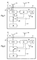
- the beacon 10 comprises a housing 11 equipped with a connector 12 for connecting the beacon to an antenna (13 or 14) external to the housing: either an antenna 13 integral with the fuselage of a helicopter, or an auxiliary antenna 14 portable which is on board the helicopter and can be connected to the portable beacon 10 by an occupant who noted the deterioration of the antenna 13 or having left the helicopter with the beacon and the auxiliary antenna.
- the beacon comprises, inside the housing 11, a shock sensor 15 such as a piezoelectric accelerometer, a distress signal transmitter circuit 16 in a suitable format (amplitude, duration, modulation, frequency, in particular), as well as a detection and control unit 18 which is connected to the sensor 15 and to the transmitter 16 via respective links 30, 31.
- a shock sensor 15 such as a piezoelectric accelerometer
- a distress signal transmitter circuit 16 in a suitable format (amplitude, duration, modulation, frequency, in particular)
- detection and control unit 18 which is connected to the sensor 15 and to the transmitter 16 via respective links 30, 31.
- the member 18 - such as a microprocessor circuit - is programmed to trigger the operation of the transmitter when an impact is detected.
- the beacon further comprises, inside the housing, an integrated antenna 19, a rocker 20 interconnected between the transmitter 16 and the connector 12 on the one hand, and between the transmitter 16 and the integrated antenna 19. secondly, and a member 21 sensitive to the electromagnetic power Pi transmitted to the connector and the electromagnetic power Pr returned by the connector.
- the integrated antenna may be a slot antenna.
- the sensitive member 21 is connected to or integrated with the detection and control member 18 and connected between the flip-flop 20 and the connector 12.
- the member 21 is thus sensitive to the standing wave ratio. ROS / VSWR in the transmission line connecting an output of the flip-flop to the connector.
- the detection and control unit 18 is connected to the flip-flop and arranged (in particular programmed) to control the delivery of the signals delivered by the transmitter to the external antenna 13 or 14, or to the integrated antenna 19, according to the state of - or level detected by - the sensitive organ 21.
- the detection and control member 18 is further arranged to scan the state of the sensitive member 21 at regular time intervals (after the detection of an incident).
- the detection and control member 18 is in particular arranged to compare the standing wave ratio ROS / VSWR with a determined value, at regular time intervals, after the detection of an incident.
- the detection and control unit 18 is also programmed to maintain unchanged the state or position (pos1 or pos2 respectively corresponding to the Figures 1 and 2 ) of the latch for a specified time (temp1, temp2): after a toggle command (of the switch 20 Figures 1 and 2 ) in the pos1 position (step 104) or in the pos2 position (step 102), a new scan (step 100) of the value of the ROS followed by the comparison (step 101) of this value to the determined value x , n ' only after the lapse of a determined duration, the duration temp1 (step 105) or the duration temp2 (step 103).
- exceeding the ROS ratio by the value x means either that the external antenna is broken or that the transmitter / external antenna link is broken; detection by the unit 18 of this overshoot then causes activation, by the unit 18 and the flip-flop 20, of the antenna internal to the beacon.
- the switchover to the antenna 19 integrated in the beacon is done only when the beacon is separated from the helicopter or when the external antenna (main fixed or auxiliary portable) is out of service.
Landscapes
- Engineering & Computer Science (AREA)
- Physics & Mathematics (AREA)
- General Physics & Mathematics (AREA)
- Remote Sensing (AREA)
- Radar, Positioning & Navigation (AREA)
- Computer Networks & Wireless Communication (AREA)
- Signal Processing (AREA)
- Astronomy & Astrophysics (AREA)
- Aviation & Aerospace Engineering (AREA)
- Transmitters (AREA)
Claims (6)
- Notfallhake (10) für ein Drehflügelflugzeug, welche von diesem Drehflügelflugzeug getrennt werden kann und im Fall eines Crashs wieder aufgesammelt werden kann, mit: einem Gehäuse (11) mit einer integrierten Antenne (19), einer Antenne (13, 14) außerhalb des Gehäuses (11), wobei das Gehäuse (11) mit der Antenne (13, 14) außerhalb des Gehäuses (11) verbunden ist, einem Störfalldetektor (15), einem Sender (16), einem Erfassungs- und Steuerorgan (18), das mit dem Detektor (15) und dem Sender (16) verbunden ist und so ausgebildet ist, dass es den Betrieb des Senders auslöst, wenn ein Störfall erfasst wird, wobei ein Kippschalter (20) zwischen dem Sender (16) und der äußeren Antenne (13, 14) einerseits und zwischen dem Sender und der integrierten Antenne (19) andererseits angeordnet ist, und mit einem Element (21), das empfindlich ist für die zur Außenantenne (13, 14) gesendete elektromagnetische Leistung (Pi), die zur Außenantenne (13, 14) übertragen wird, und für die elektromagnetische Leistung (Pr), die von dieser Außenantenne (13, 14) zurückgesendet wird, wobei das empfindliche Element (21) mit dem Erfassungs- und Steuerorgan (18) verbunden ist oder in dieses integriert ist,
dadurch gekennzeichnet, dass das Gehäuse (11) mit einem lösbaren Stecker (12) zur Verbindung mit der Außenantenne (13, 14) ausgerüstet ist, und
dadurch, dass die Außenantenne (13, 14) fest mit dem Rumpf des Drehflügelflugzeugs verbunden ist, und
dadurch, dass das Erfassungs- und Steuerorgan (18) mit dem Kippschalter (20) und dem lösbaren Stecker (12) verbunden ist, um das Senden von von dem Sender (16) gelieferten Signalen, entweder an die Außenantenne (13, 14) oder an die integrierte Antenne (19) zu steuern, je nach dem Zustand des empfindlichen Elements (21) und des lösbaren Steckers (12), wobei das Erfassungs- und Steuerorgan (18) programmiert ist, um den Zustand des empfindlichen Elements (21) in regelmäßigen Zeitintervallen nach dem Erfassen eines Störfalls zu prüfen, wobei dieses empfindliche Element (21) das Stehwellenverhältnis ROS (VSWR) in einer Übertragungsleitung misst, die einen Ausgang des Kippschalters (20) mit dem lösbaren Stecker (12) verbindet. - Bake (10) nach Anspruch 1, dadurch gekennzeichnet, dass das Erfassungs- und Steuerorgan (18) so ausgebildet ist, dass es das Stehwellenverhältnis (ROS) (VSWR) mit einem vorbestimmten Wert in regelmäßigen Zeitintervallen nach der Erfassung eines Störfalls vergleicht.
- Bake (10) nach einem der Ansprüche 1 bis 2, dadurch gekennzeichnet, dass das Erfassungs- und Steuerorgan (18) so ausgebildet ist, dass es den Zustand oder die Stellung (pos1, pos2) des Kippschalters während einer vorbestimmten Zeitdauer (temp1, temp2) unverändert lässt.
- Bake (10) nach einem der Ansprüche 1 bis 3, dadurch gekennzeichnet, dass die integrierte Antenne eine Schlitzantenne ist.
- Bake (10) nach einem der Ansprüche 1 bis 4, dadurch gekennzeichnet, dass der Sender zum Senden von Signalen mit mindestens zwei oder drei Frequenzen ausgebildet ist.
- Bake (10) nach einem der Ansprüche 1 bis 5, dadurch gekennzeichnet, dass der Sender zum Senden von Signalen mit mindestens einer der Frequenzen 121,5 MHz, 243 MHz, 406,025 MHz ausgebildet ist.
Applications Claiming Priority (1)
| Application Number | Priority Date | Filing Date | Title |
|---|---|---|---|
| FR0705039A FR2918802B1 (fr) | 2007-07-12 | 2007-07-12 | Balise de detresse amelioree |
Publications (2)
| Publication Number | Publication Date |
|---|---|
| EP2015100A1 EP2015100A1 (de) | 2009-01-14 |
| EP2015100B1 true EP2015100B1 (de) | 2016-03-23 |
Family
ID=39135137
Family Applications (1)
| Application Number | Title | Priority Date | Filing Date |
|---|---|---|---|
| EP08012230.2A Active EP2015100B1 (de) | 2007-07-12 | 2008-07-07 | Abnehmbare Notfunkbake für Drehflügler |
Country Status (5)
| Country | Link |
|---|---|
| US (1) | US7916084B2 (de) |
| EP (1) | EP2015100B1 (de) |
| KR (1) | KR101066904B1 (de) |
| CN (1) | CN101357688B (de) |
| FR (1) | FR2918802B1 (de) |
Families Citing this family (9)
| Publication number | Priority date | Publication date | Assignee | Title |
|---|---|---|---|---|
| US8508408B2 (en) * | 2010-08-31 | 2013-08-13 | Raytheon Company | Method and apparatus for reconfiguring a photonic TR beacon |
| FR2976913B1 (fr) * | 2011-06-21 | 2014-01-17 | Eads Europ Aeronautic Defence | Dispositif combine de balise de secours et enregistreur de vol pour aeronef et aeronef equipe d'un tel dispositif |
| MY181663A (en) * | 2011-12-16 | 2020-12-31 | Mimos Berhad | A system and method to detect and switch between internal and external antennas |
| FR2996313B1 (fr) * | 2012-10-02 | 2014-10-03 | Elta | Systeme de balise de detresse pour aeronef ou autre vehicule |
| GB201218573D0 (en) * | 2012-10-16 | 2012-11-28 | Elevacion Ltd | A case for releasably securing a mobile communication device in a sealed environment |
| US9998863B2 (en) * | 2013-08-19 | 2018-06-12 | Estimote Polska Sp. Z O. O. | System and method for providing content using beacon systems |
| KR20170001347A (ko) | 2015-06-26 | 2017-01-04 | 쌍용자동차 주식회사 | 비콘을 이용한 차량사고 통보장치 |
| US10450084B2 (en) * | 2016-02-25 | 2019-10-22 | The Boeing Company | Emergency locator transmitter activation device for enhanced emergency location performance |
| CN110086494A (zh) * | 2019-04-24 | 2019-08-02 | 大陆汽车电子(长春)有限公司 | 车用无线通信装置、车辆无线通信方法 |
Family Cites Families (18)
| Publication number | Priority date | Publication date | Assignee | Title |
|---|---|---|---|---|
| US3354395A (en) * | 1965-08-09 | 1967-11-21 | Merck John Wayne | Automatic emergency signaling beacon |
| US3978410A (en) * | 1972-11-17 | 1976-08-31 | Nasa | Aircraft-mounted crash-activated transmitter device |
| US4630289A (en) * | 1979-12-21 | 1986-12-16 | Wren Paul E | Emergency locator transmitter incident time correlator |
| FR2660093B1 (fr) | 1990-03-26 | 1992-07-24 | Etudes Realis Protect Electron | Dispositif d'alimentation d'une balise de detresse equipant par exemple un navire. |
| US5425076A (en) * | 1992-06-30 | 1995-06-13 | Minnesota Mining And Manufacturing Company | Cellular communications test system |
| FR2695478B1 (fr) * | 1992-09-08 | 1994-11-18 | Aerospatiale | Détecteur de chocs et balise de détresse pour aéronef, comportant un tel détecteur. |
| US6411260B1 (en) * | 1994-08-18 | 2002-06-25 | Alliedsignal Inc. | Triple frequency, split monopole, emergency locator transmitter antenna |
| USH1560H (en) * | 1994-09-06 | 1996-07-02 | The United States Of America As Represented By The Secretary Of The Air Force | Crash site locator beacon |
| JPH11177462A (ja) * | 1997-12-12 | 1999-07-02 | Fujitsu Ten Ltd | メーデーシステム用装置 |
| FR2776391B1 (fr) | 1998-03-18 | 2000-09-01 | Serpe Iesm Societe D Etudes Et | Systeme de gestion centralisee de balises de detresse |
| US6324393B1 (en) * | 1998-04-21 | 2001-11-27 | Irving Doshay | Auto locating emergency rescue transmitter (ALERT) |
| US6275164B1 (en) * | 1998-12-11 | 2001-08-14 | Macconnell John W. | Emergency locator system |
| US6260508B1 (en) * | 1999-09-08 | 2001-07-17 | Lynn Morse | Position indicating device and method of use |
| US6208269B1 (en) * | 1999-12-29 | 2001-03-27 | The Boeing Company | Automatically activated rescue radio and associated method |
| FR2836722B1 (fr) * | 2002-03-01 | 2006-12-08 | Airbus France | Balise de detresse, procede et dispositif de surveillance de signaux de detresse, et vehicule comprenant un tel dispositif |
| FR2873451B1 (fr) | 2004-07-23 | 2006-10-06 | Martec Serpe Iesm Sa | Balise de localisation et dispositif de suivi d'un objet flottant |
| DE102004036878B4 (de) * | 2004-07-29 | 2008-04-10 | Dräger Safety AG & Co. KGaA | Verfahren und Vorrichtung zur Funkübertragung von in Körpernähe generierten Signalen |
| US7162395B1 (en) * | 2004-09-22 | 2007-01-09 | Jodanti Enterprises Ltd. | Cospas-sarsat beacon tester in a removable expansion card for a handheld computing device |
-
2007
- 2007-07-12 FR FR0705039A patent/FR2918802B1/fr active Active
-
2008
- 2008-07-07 EP EP08012230.2A patent/EP2015100B1/de active Active
- 2008-07-11 US US12/171,310 patent/US7916084B2/en active Active
- 2008-07-11 KR KR1020080067461A patent/KR101066904B1/ko active Active
- 2008-07-14 CN CN2008101316237A patent/CN101357688B/zh active Active
Also Published As
| Publication number | Publication date |
|---|---|
| CN101357688B (zh) | 2011-05-18 |
| FR2918802A1 (fr) | 2009-01-16 |
| FR2918802B1 (fr) | 2014-05-23 |
| US7916084B2 (en) | 2011-03-29 |
| KR101066904B1 (ko) | 2011-09-27 |
| CN101357688A (zh) | 2009-02-04 |
| US20090027269A1 (en) | 2009-01-29 |
| EP2015100A1 (de) | 2009-01-14 |
| KR20090006786A (ko) | 2009-01-15 |
Similar Documents
| Publication | Publication Date | Title |
|---|---|---|
| EP2015100B1 (de) | Abnehmbare Notfunkbake für Drehflügler | |
| US6380883B1 (en) | High performance vehicle radar system | |
| US6400308B1 (en) | High performance vehicle radar system | |
| EP1354219B1 (de) | System zur überwachung von reifen eines fahrzeugs mit einer einrichtung zum automatischen finden von radsendern | |
| KR102108341B1 (ko) | 차량용 레이더 고장 진단 방법 및 이를 위한 시스템 | |
| FR2497948A1 (fr) | Systeme d'interrogation pour le controle a distance de la pression de l'air d'un pneumatique | |
| EP1147953A3 (de) | Sicherheitssystem zur Verhinderung eines unberechtigten Startens eines Fahrzeugmotors | |
| FR3109850A1 (fr) | Dispositif pour systeme electronique de controle de la pression des pneus d’un vehicule automobile | |
| EP0955431B1 (de) | Sicherheitssystem für eine Kraftfahrzeugöffnung | |
| EP1762541B1 (de) | System zur Überprüfung der Verbindung von Verbindungsstücken | |
| EP2993130B1 (de) | Signallicht und herstellungsverfahren | |
| BE1019955A3 (fr) | Systeme de surveillance pour un emetteur-recepteur doppler. | |
| EP1514133B1 (de) | Gezogene atrappe und verfahren zu ihrer verbesserung | |
| US20240036157A1 (en) | Radar sensor device and method for self-testing | |
| EP1188626B1 (de) | Kraftfahrzeug ausgerüstet mit einem handfreien Zugangssystem, mit einer auf einer Lenksäuleneinheit montierten Empfangsantenne | |
| FR2629404A1 (fr) | Installation d'avertisseur d'accident pour automobile | |
| BE1007985A5 (fr) | Installation de telecommande, notamment pour l'ouverture et/ou la fermeture de portes, de garage ou de vehicules automobiles. | |
| FR3027455A1 (fr) | Batterie utilisee en tant qu'antenne | |
| EP1340995B1 (de) | Notbake, Verfahren und Vorrichtung zur Überwachung von Notsignalen und eine solche Vorrichtung einschliessendes Fahrzeug | |
| US20120206305A1 (en) | Testing of Automobile Mounted Antennas | |
| FR3111241A1 (fr) | Système de détection radar d’un véhicule | |
| FR2593761A1 (fr) | Systeme de signalisation ferroviaire pour la reconnaissance d'un vehicule predetermine a son passage en un point donne | |
| FR3013032A1 (fr) | Balise de detresse integree a l'empennage vertical d'un aeronef | |
| FR3000272A1 (fr) | Dispositif d'actionnement a distance d'un dispositif de commande automatique ou semi-automatique d'un vehicule | |
| US8953151B2 (en) | Method for determining the presence of a transmitter and a receiver in a vehicle and a system designed for carrying out the same |
Legal Events
| Date | Code | Title | Description |
|---|---|---|---|
| PUAI | Public reference made under article 153(3) epc to a published international application that has entered the european phase |
Free format text: ORIGINAL CODE: 0009012 |
|
| AK | Designated contracting states |
Kind code of ref document: A1 Designated state(s): AT BE BG CH CY CZ DE DK EE ES FI FR GB GR HR HU IE IS IT LI LT LU LV MC MT NL NO PL PT RO SE SI SK TR |
|
| AX | Request for extension of the european patent |
Extension state: AL BA MK RS |
|
| 17P | Request for examination filed |
Effective date: 20090217 |
|
| AKX | Designation fees paid |
Designated state(s): GB IT |
|
| REG | Reference to a national code |
Ref country code: DE Ref legal event code: 8566 |
|
| 17Q | First examination report despatched |
Effective date: 20111214 |
|
| RAP1 | Party data changed (applicant data changed or rights of an application transferred) |
Owner name: AIRBUS HELICOPTERS |
|
| GRAP | Despatch of communication of intention to grant a patent |
Free format text: ORIGINAL CODE: EPIDOSNIGR1 |
|
| RIC1 | Information provided on ipc code assigned before grant |
Ipc: H01Q 21/28 20060101ALI20151029BHEP Ipc: G01S 1/68 20060101AFI20151029BHEP Ipc: G01S 5/02 20100101ALI20151029BHEP |
|
| INTG | Intention to grant announced |
Effective date: 20151117 |
|
| GRAS | Grant fee paid |
Free format text: ORIGINAL CODE: EPIDOSNIGR3 |
|
| GRAA | (expected) grant |
Free format text: ORIGINAL CODE: 0009210 |
|
| AK | Designated contracting states |
Kind code of ref document: B1 Designated state(s): GB IT |
|
| REG | Reference to a national code |
Ref country code: GB Ref legal event code: FG4D Free format text: NOT ENGLISH |
|
| PLBE | No opposition filed within time limit |
Free format text: ORIGINAL CODE: 0009261 |
|
| STAA | Information on the status of an ep patent application or granted ep patent |
Free format text: STATUS: NO OPPOSITION FILED WITHIN TIME LIMIT |
|
| 26N | No opposition filed |
Effective date: 20170102 |
|
| P01 | Opt-out of the competence of the unified patent court (upc) registered |
Effective date: 20230530 |
|
| PGFP | Annual fee paid to national office [announced via postgrant information from national office to epo] |
Ref country code: IT Payment date: 20250724 Year of fee payment: 18 |
|
| PGFP | Annual fee paid to national office [announced via postgrant information from national office to epo] |
Ref country code: GB Payment date: 20250722 Year of fee payment: 18 |