EP2018292B1 - Motorischer stellantrieb für einen fahrzeugsitz - Google Patents
Motorischer stellantrieb für einen fahrzeugsitz Download PDFInfo
- Publication number
- EP2018292B1 EP2018292B1 EP07724810A EP07724810A EP2018292B1 EP 2018292 B1 EP2018292 B1 EP 2018292B1 EP 07724810 A EP07724810 A EP 07724810A EP 07724810 A EP07724810 A EP 07724810A EP 2018292 B1 EP2018292 B1 EP 2018292B1
- Authority
- EP
- European Patent Office
- Prior art keywords
- motor
- driven actuator
- sealing element
- gear stage
- gear
- Prior art date
- Legal status (The legal status is an assumption and is not a legal conclusion. Google has not performed a legal analysis and makes no representation as to the accuracy of the status listed.)
- Ceased
Links
Images

Classifications
-
- B—PERFORMING OPERATIONS; TRANSPORTING
- B60—VEHICLES IN GENERAL
- B60N—SEATS SPECIALLY ADAPTED FOR VEHICLES; VEHICLE PASSENGER ACCOMMODATION NOT OTHERWISE PROVIDED FOR
- B60N2/00—Seats specially adapted for vehicles; Arrangement or mounting of seats in vehicles
- B60N2/02—Seats specially adapted for vehicles; Arrangement or mounting of seats in vehicles the seat or part thereof being movable, e.g. adjustable
-
- H—ELECTRICITY
- H02—GENERATION; CONVERSION OR DISTRIBUTION OF ELECTRIC POWER
- H02K—DYNAMO-ELECTRIC MACHINES
- H02K5/00—Casings; Enclosures; Supports
- H02K5/04—Casings or enclosures characterised by the shape, form or construction thereof
- H02K5/12—Casings or enclosures characterised by the shape, form or construction thereof specially adapted for operating in liquid or gas
- H02K5/124—Sealing of shafts
-
- B—PERFORMING OPERATIONS; TRANSPORTING
- B60—VEHICLES IN GENERAL
- B60N—SEATS SPECIALLY ADAPTED FOR VEHICLES; VEHICLE PASSENGER ACCOMMODATION NOT OTHERWISE PROVIDED FOR
- B60N2/00—Seats specially adapted for vehicles; Arrangement or mounting of seats in vehicles
- B60N2/02—Seats specially adapted for vehicles; Arrangement or mounting of seats in vehicles the seat or part thereof being movable, e.g. adjustable
- B60N2/0224—Non-manual adjustments, e.g. with electrical operation
- B60N2/02246—Electric motors therefor
-
- B—PERFORMING OPERATIONS; TRANSPORTING
- B60—VEHICLES IN GENERAL
- B60N—SEATS SPECIALLY ADAPTED FOR VEHICLES; VEHICLE PASSENGER ACCOMMODATION NOT OTHERWISE PROVIDED FOR
- B60N2/00—Seats specially adapted for vehicles; Arrangement or mounting of seats in vehicles
- B60N2/02—Seats specially adapted for vehicles; Arrangement or mounting of seats in vehicles the seat or part thereof being movable, e.g. adjustable
- B60N2/22—Seats specially adapted for vehicles; Arrangement or mounting of seats in vehicles the seat or part thereof being movable, e.g. adjustable the back-rest being adjustable
-
- H—ELECTRICITY
- H02—GENERATION; CONVERSION OR DISTRIBUTION OF ELECTRIC POWER
- H02K—DYNAMO-ELECTRIC MACHINES
- H02K15/00—Processes or apparatus specially adapted for manufacturing, assembling, maintaining or repairing of dynamo-electric machines
- H02K15/02—Processes or apparatus specially adapted for manufacturing, assembling, maintaining or repairing of dynamo-electric machines of stator or rotor bodies
-
- H—ELECTRICITY
- H02—GENERATION; CONVERSION OR DISTRIBUTION OF ELECTRIC POWER
- H02K—DYNAMO-ELECTRIC MACHINES
- H02K5/00—Casings; Enclosures; Supports
- H02K5/04—Casings or enclosures characterised by the shape, form or construction thereof
- H02K5/10—Casings or enclosures characterised by the shape, form or construction thereof with arrangements for protection from ingress, e.g. water or fingers
-
- Y—GENERAL TAGGING OF NEW TECHNOLOGICAL DEVELOPMENTS; GENERAL TAGGING OF CROSS-SECTIONAL TECHNOLOGIES SPANNING OVER SEVERAL SECTIONS OF THE IPC; TECHNICAL SUBJECTS COVERED BY FORMER USPC CROSS-REFERENCE ART COLLECTIONS [XRACs] AND DIGESTS
- Y10—TECHNICAL SUBJECTS COVERED BY FORMER USPC
- Y10T—TECHNICAL SUBJECTS COVERED BY FORMER US CLASSIFICATION
- Y10T29/00—Metal working
- Y10T29/49—Method of mechanical manufacture
- Y10T29/49002—Electrical device making
- Y10T29/49009—Dynamoelectric machine
Definitions
- the integrated sealing element which has the assembled motorized actuator during manufacture to protect the motor and / or its electrical contact and / or at least one of the gear stages, the components of the motorized actuator can be subjected in the assembled state of a partially aggressive surface finishing without the delicate electronic and mechanical parts are damaged.
- the sealing element is removed in the built-in motor actuator, - while maintaining the sealing effect during the aggressive sections of the surface finishing - free spaces for clearance compensation or compensation for a wobbling motion can be provided.
- the free spaces also reduce the friction and thus the operating costs of the motorized actuator.
- caps or the like which are temporarily mounted for the aggressive sections of the surface finishing, as well as to a change in the process flow, according to which the sensitive parts are installed only after the aggressive sections of the surface finishing, assembly costs and thus the installation costs are kept small.
- the sealing element is introduced during assembly of the motorized actuator as a separate component, for example in the form of a seal, or formed on another component, for example, formed as a thin layer of material or a material constriction.
- a plurality of sealing elements are provided.
- a part of the existing sealing elements can be provided in one way, the other part in the other way.
- the existing sealing members provide for the motorized actuator to form a closed-interface system during the aggressive portions of the surface treatment, preferably cleaning and / or painting, while the removed sealing members form the motorized actuator into a system with open mechanical and electrical interfaces makes, namely with at least one output and at least one electrical contact.
- the sealing element may be thermally removable, for example by formation of a thermoplastic or similar material, which is present during the aggressive sections of the surface finishing, preferably cleaning and / or painting, whereas, during the non-aggressive final sections of the surface finishing, preferably a drying or other thermal treatment, automatically removes or shrinks. It is preferred that the thermoplastic material of the sealing element during drying or other thermal treatment shrinks or liquefies or softens and is removed by gravity or capillary action or the like from the former sealing space, preferably in designated cavities of the housing.
- the sealing element may also be mechanically removable, for example by training as a thin film or by providing a predetermined breaking point or a film hinge to a component of the motorized actuator, wherein the sealing element before installation, by the installation or by the commissioning of the motorized actuator at its destination destroyed, broken out, opened, completely or partially folded down or otherwise removed.
- the sealing element is provided on a plug of an electrical contact, it can be removed by the anyway necessary mounting a mating connector.
- the sealing element is provided on a driver or other drive element, it can be removed by the anyway necessary mounting a transmission rod.
- the first gear stage is preferably as a circular thrust transmission (surface pressure transmission) with housing-fixed guide elements for the pinion and simple rotation formed of the gear, as for example in the US 4,228,698 A is disclosed, but can also be designed as Oldham coupling (crank gear), as shown for example in the EP 0 450 324 B1 is described. Due to the circular thrust movement, the teeth do not need involute to produce a line contact, but can carry flat and thus endure much higher loads. The engagement of several teeth and thus a reduction of the backlash is also advantageous in this regard. In case of imbalances in the gear stages, a mass balance can be provided, so that a harmonious run is guaranteed.
- a circular thrust transmission surface pressure transmission
- Oldham coupling crank gear
- the second gear stage is - up to the disc shape - built according to the load-bearing transmission, as in the DE 10 2004 019 466 A1 is described, ie two by a (preferably self-locking) eccentric planetary gear (for locking and adjusting) interconnected fitting parts perform relative to each other a rotational movement with superimposed wobble.
- a (preferably self-locking) eccentric planetary gear (for locking and adjusting) interconnected fitting parts perform relative to each other a rotational movement with superimposed wobble.
- the fitting parts have no disc shape, at most a small part of the second gear stage can be integrated into the housing. It is conceivable in all variants of the second gear stage to provide a further gear stage, for example between the first and the second gear stage.
- a hollow shaft design allows easy connection of a transmission rod between the two vehicle seat sides, preferably by a profiled central receptacle in the drive member for the load-bearing transmission, so in this case the driver of the second gear stage.
- a motorized actuator 1 for a vehicle seat 2, for example a motor vehicle, has a motor housing 3.
- a rotatably mounted rotor 6, whose axis of rotation is designated as the main axis A and defines the directional information used below, and a fixedly mounted in the motor housing 3 stator 7 is arranged.
- the trained as a hollow shaft rotor 6 has on its outer side in the circumferential direction a plurality of permanent magnets. Radially outside the permanent magnets, the stator 7 is arranged with a plurality of stator poles and winding packages. The rotor 6 and the stator 7 together form an electronically commutated motor 11 integrated into the motorized actuator 1.
- a circuit board 13 is provided, which is arranged axially offset from the stator 7 in the motor housing 3.
- the motor may alternatively be brush commutated.
- the plug 15 encloses in its interior at least one electrical contact 17, which is connected to the circuit board 13.
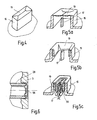
- the plug 15 is formed in the manufacture of the motor housing 3 with a lid, hereinafter referred to as the first sealing element 19, as in Fig. 4 shown.
- a material constriction in the form of a predetermined breaking point or a film hinge is preferably provided, or the first sealing element 19 is completely formed as a thin film.
- the motorized actuator 1 has an integrated first gear stage 21 on the principle of operation of a circular thrust gear (surface pressure gearbox), which on Motor 11 is arranged on the output side.
- the output of the motor 11 forming the rotor 6 is axially extended beyond the stator 7 out and axially one behind the other with two radially projecting cams or the like, which are circumferentially offset by 180 ° to each other.
- the two axially successively arranged gears 24 mesh with a common ring gear 25, wherein the engagement - due to the bearing of the gear wheels 24 - takes place at two opposite points of the ring gear 25.
- the ring gear 25 is fixedly connected to the motor housing 3. The gears 24 thus perform when driven by the rotor 6 a rotational movement with superimposed wobble.
- a driver 28 is provided as output of the first gear stage 21.
- the driver 28 is designed in a hollow shaft design and preferably extends over the entire axial length of the motorized actuator 1.
- the driver 28 is disposed over part of its length within the rotor 6 and supports the same.
- a seal hereinafter referred to as a second sealing element 29, is inserted between the driver 28 and the motor housing 3 during assembly.
- the motor housing 3 has at this point cavities 3a, as in Fig. 2 shown.
- the driver 28 has a radially outwardly projecting flange, which is arranged radially within a radially inwardly projecting flange of the ring gear 25.
- a further seal referred to below as the third sealing element 30, is introduced between the driver and the ring gear 25 between the two flanges.
- the ring gear 25 has at this point on cavities 25a.
- From the flange of the driver 28 are axially from a plurality of guide elements, for example, bolts, which engage with play in a corresponding number of openings of each gear 24.
- the driver 28 is at the same time part of a second gear stage 31.
- the second gear stage 31 has a first fitting 33 with a concentric to the main axis A gear and a second fitting part 34 with a ring gear, which communicate with each other to form a Exzenterumlaufgetriebe geared and by an eccentric to a relative rolling movement to each other, consisting of a rotational movement and a superimposed wobble, to be driven.
- the eccentric is formed by the driver 28 and a wedge system for locking and clearance.
- Such eccentric planetary gear is in principle in the DE 44 36 101 A1 whose disclosure content is explicitly included.
- the presently used disc shape of the second gear stage 31 is in the DE 101 05 282 A1 whose disclosure content is also explicitly included.
- a Umklamm ceremoniessring 43 is fixedly connected to the motor housing 3, the ring gear 25 and the first fitting part 33, whereby a common housing 45 is formed, and engages over the second fitting part 34 at its radially outer edge, optionally with the interposition of sliding elements to reduce the friction.
- the motorized actuator 1 After painting, the motorized actuator 1 is subjected to drying in a drying oven, that is, thermally treated.
- the components of the engine 11 and the first gear stage 21 easily withstand the temperature used of about 140 ° to 160 ° C due to their design to similarly high operating temperature peaks.
- the two sealing elements 29 and 30 consist of a thermoplastic material whose melting point coincides with or lies below the temperature of the drying oven. As a result, the sealing elements 29 and 30 liquefy in the drying oven.
- the material of the sealing elements 29 and 30 can flow from the former sealing space into the cavities 3a and 25a kept free, with a low volume of the cavities 3a and 25a, for example automatically due to the capillary action.
- the sealing elements 29 and 30 In order to keep the cavities 3a and 25a free when introducing the sealing elements 29 and 30, it is possible, for example, to provide placeholders, which are then removed again or fall out with the liquefaction of the sealing elements 29 and 30.
- the former sealing space is now available as clearance for the driver 28 for a clearance compensation or the compensation of a tumbling motion.
- the material of the sealing elements 29 and 30 may shrink during drying or other thermal treatment and at least partially release the former sealing space. In all Cases are the previously existing contact forces between the parts to be sealed repealed.
- the motorized actuator 1 can now be installed at its destination and ready for use.
- the first sealing element 19 is destroyed by means of a tool or preferably with the mating connector 55 to be plugged in or on the plug 15, broken out or completely or partially removed or otherwise removed and the mating connector 55 inserted or pushed.
- the steps are schematic in Figs. 5A to 5C shown. Folded parts of the first sealing element 19 preferably act as a latching for the mating connector 55.
- the first sealing element 19 can also be removed thermally, ie as the sealing elements 29 and 30.
- the thermal treatment for removing the first sealing element 19 may alternatively for mechanical removal or as a preliminary work be provided for this purpose.
- the tool or mating connector 55 would only eliminate the remains of the first sealing element 19.
- the second gear stage 31 serves as a load-absorbing gear, which lies in the power flow between the two of the motor actuator 1 relative to each other to moving components of the vehicle seat 2 and in particular absorbs the forces and forwards in the event of a crash.
- the motorized actuator 1 according to the invention can be used, for example, to adjust the inclination of a backrest 58 of the vehicle seat 2 relative to a seat part 59 of the vehicle seat 2, so that the second gear stage 41 is located in the power flow between the backrest 58 and the seat part 59.
- the common housing 45 is connected to the structure of the seat part 59, while the second fitting part 34 is connected as an output to the structure of the back 58.
- the motorized actuator 1 can also be used for height adjustment of the seat part 59 by the motorized actuator 1, for example, between a rocker on the one hand and a seat frame or a seat rail on the other hand is effective. There are further possible uses of the motorized actuator between other relatively movable components of the vehicle seat 2 possible.
Landscapes
- Engineering & Computer Science (AREA)
- Aviation & Aerospace Engineering (AREA)
- Transportation (AREA)
- Mechanical Engineering (AREA)
- Power Engineering (AREA)
- Manufacturing & Machinery (AREA)
- Connection Of Motors, Electrical Generators, Mechanical Devices, And The Like (AREA)
- Seats For Vehicles (AREA)
- Chairs For Special Purposes, Such As Reclining Chairs (AREA)
- Retarders (AREA)
- Gasket Seals (AREA)
- Motor Or Generator Frames (AREA)
- General Details Of Gearings (AREA)
Priority Applications (1)
| Application Number | Priority Date | Filing Date | Title |
|---|---|---|---|
| PL07724810T PL2018292T3 (pl) | 2006-05-19 | 2007-05-03 | Napęd silnikowy siedzenia pojazdu |
Applications Claiming Priority (2)
| Application Number | Priority Date | Filing Date | Title |
|---|---|---|---|
| DE102006023536A DE102006023536A1 (de) | 2006-05-19 | 2006-05-19 | Motorischer Stellantrieb für einen Fahrzeugsitz |
| PCT/EP2007/003884 WO2007134704A1 (de) | 2006-05-19 | 2007-05-03 | Motorischer stellantrieb für einen fahrzeugsitz |
Publications (2)
| Publication Number | Publication Date |
|---|---|
| EP2018292A1 EP2018292A1 (de) | 2009-01-28 |
| EP2018292B1 true EP2018292B1 (de) | 2009-11-18 |
Family
ID=38292686
Family Applications (1)
| Application Number | Title | Priority Date | Filing Date |
|---|---|---|---|
| EP07724810A Ceased EP2018292B1 (de) | 2006-05-19 | 2007-05-03 | Motorischer stellantrieb für einen fahrzeugsitz |
Country Status (8)
| Country | Link |
|---|---|
| US (1) | US7726744B2 (pl) |
| EP (1) | EP2018292B1 (pl) |
| JP (1) | JP4786743B2 (pl) |
| KR (1) | KR101277144B1 (pl) |
| DE (2) | DE102006023536A1 (pl) |
| PL (1) | PL2018292T3 (pl) |
| RU (1) | RU2417907C2 (pl) |
| WO (1) | WO2007134704A1 (pl) |
Families Citing this family (16)
| Publication number | Priority date | Publication date | Assignee | Title |
|---|---|---|---|---|
| DE102006042273B4 (de) * | 2006-09-08 | 2009-12-31 | Lander Automotive Gmbh | Sitzverstellvorrichtung für einen Fahrzeugsitz |
| DE102011075183A1 (de) | 2010-08-31 | 2012-03-01 | Brose Fahrzeugteile Gmbh & Co. Kg, Coburg | Verstellantrieb für eine Verstelleinrichtung eines Kraftfahrzeugsitzes |
| EP2728985B1 (de) | 2012-11-02 | 2018-01-31 | Siemens Schweiz AG | Stellantrieb mit elektrischer Steckverbindung |
| KR102212161B1 (ko) | 2015-01-20 | 2021-02-04 | 엘지이노텍 주식회사 | 모터의 하우징 및 이를 포함하는 모터 |
| US11124093B2 (en) | 2018-08-08 | 2021-09-21 | Fisher & Company, Incorporated | Recliner mechanism for seat assembly and method of manufacturing |
| US11260777B2 (en) | 2018-08-29 | 2022-03-01 | Fisher & Company, Incorporated | Recliner heart for seat recliner assembly |
| US11364577B2 (en) * | 2019-02-11 | 2022-06-21 | Fisher & Company, Incorporated | Recliner mechanism for seat assembly and method of manufacturing |
| DE102019204339A1 (de) | 2019-03-28 | 2020-10-01 | Brose Fahrzeugteile SE & Co. Kommanditgesellschaft, Coburg | Beschlaganordnung mit abgedichteter Lagerbuchse |
| US11845367B2 (en) | 2019-04-18 | 2023-12-19 | Fisher & Company, Incorporated | Recliner heart having lubricant member |
| US11052797B2 (en) | 2019-08-09 | 2021-07-06 | Fisher & Company, Incorporated | Recliner heart for seat assembly |
| US11192473B2 (en) | 2019-08-30 | 2021-12-07 | Fisher & Company, Incorporated | Release handle for recliner mechanism of vehicle seat |
| US11607976B2 (en) | 2020-03-06 | 2023-03-21 | Fisher & Company, Incorporated | Recliner mechanism having bracket |
| KR102535831B1 (ko) * | 2020-03-11 | 2023-05-23 | 주식회사 아모텍 | 전기모터 |
| US11766957B2 (en) | 2021-02-16 | 2023-09-26 | Fisher & Company, Incorporated | Release mechanism for seat recliner assembly |
| US11897372B2 (en) | 2021-05-06 | 2024-02-13 | Fisher & Company, Incorporated | Recliner heart having biasing members |
| US11850975B2 (en) | 2021-06-11 | 2023-12-26 | Fisher & Company, Incorporated | Vehicle seat recliner mechanism with welded spring |
Family Cites Families (12)
| Publication number | Priority date | Publication date | Assignee | Title |
|---|---|---|---|---|
| US4228698A (en) * | 1978-05-08 | 1980-10-21 | Winiasz Michael E | Speed reducer |
| EP0450324B1 (de) | 1990-03-16 | 1994-07-20 | C. Rob. Hammerstein GmbH | Taumelgetriebe für einen verstellbaren Fahrzeugsitz |
| DE4436101C5 (de) | 1993-11-30 | 2008-12-11 | Keiper Gmbh & Co.Kg | Lehneneinstellbeschlag für Sitze mit verstellbarer Rückenlehne, insbesondere Kraftfahrzeugsitze |
| DE19709852C2 (de) * | 1997-03-11 | 2003-08-21 | Keiper Gmbh & Co Kg | Getriebebaueinheit zur Verstellung von Sitzen, insbesondere Kraftfahrzeugsitzen |
| JP4250823B2 (ja) * | 1999-09-16 | 2009-04-08 | アイシン精機株式会社 | 直流ブラシモータ |
| DE19962225A1 (de) * | 1999-12-22 | 2001-06-28 | Breed Automotive Tech | Vorrichtung zur Verstellung der Neigung einer Rückenlehne eines Fahrzeugsitzes |
| DE10105282B4 (de) * | 2001-02-06 | 2005-03-24 | Keiper Gmbh & Co. Kg | Beschlag für einen Fahrzeugsitz |
| DE10139217A1 (de) * | 2001-08-09 | 2003-03-13 | Dynamit Nobel Ag | Einrichtung zum Schließen von Kontakten |
| DE10141891A1 (de) | 2001-08-28 | 2003-03-20 | Bosch Gmbh Robert | Elektrische Maschine |
| DE102004019466B4 (de) * | 2004-04-15 | 2006-07-13 | Keiper Gmbh & Co.Kg | Einstellvorrichtung für einen Fahrzeugsitz |
| DE102004019471B4 (de) * | 2004-04-15 | 2014-01-02 | Keiper Gmbh & Co. Kg | Antriebseinheit für einen Fahrzeugsitz |
| RU42799U1 (ru) * | 2004-05-31 | 2004-12-20 | Шишкин Владимир Ильич | Сиденье транспортного средства |
-
2006
- 2006-05-19 DE DE102006023536A patent/DE102006023536A1/de not_active Withdrawn
-
2007
- 2007-05-03 WO PCT/EP2007/003884 patent/WO2007134704A1/de not_active Ceased
- 2007-05-03 KR KR1020087008472A patent/KR101277144B1/ko not_active Expired - Fee Related
- 2007-05-03 EP EP07724810A patent/EP2018292B1/de not_active Ceased
- 2007-05-03 DE DE502007002055T patent/DE502007002055D1/de active Active
- 2007-05-03 PL PL07724810T patent/PL2018292T3/pl unknown
- 2007-05-03 JP JP2009510316A patent/JP4786743B2/ja not_active Expired - Fee Related
- 2007-05-03 RU RU2008150046/11A patent/RU2417907C2/ru not_active IP Right Cessation
-
2008
- 2008-11-14 US US12/291,967 patent/US7726744B2/en not_active Expired - Fee Related
Also Published As
| Publication number | Publication date |
|---|---|
| DE502007002055D1 (de) | 2009-12-31 |
| RU2417907C2 (ru) | 2011-05-10 |
| RU2008150046A (ru) | 2010-06-27 |
| KR101277144B1 (ko) | 2013-06-20 |
| PL2018292T3 (pl) | 2010-04-30 |
| JP4786743B2 (ja) | 2011-10-05 |
| EP2018292A1 (de) | 2009-01-28 |
| US20090072602A1 (en) | 2009-03-19 |
| DE102006023536A1 (de) | 2007-11-29 |
| US7726744B2 (en) | 2010-06-01 |
| JP2009538105A (ja) | 2009-10-29 |
| WO2007134704A1 (de) | 2007-11-29 |
| KR20090010017A (ko) | 2009-01-28 |
Similar Documents
| Publication | Publication Date | Title |
|---|---|---|
| EP2018292B1 (de) | Motorischer stellantrieb für einen fahrzeugsitz | |
| DE102005034930A1 (de) | Elektrisch verstellbares Getriebe | |
| WO2013037683A2 (de) | Antriebseinrichtung | |
| EP2177789A2 (de) | Stellantrieb mit einem Elektromotor und einem Planetengetriebe | |
| DE102012210169A1 (de) | Exzentergetriebe | |
| WO2001004512A1 (de) | Mehrstufiges stirnradgetriebe | |
| DE102015204328A1 (de) | Aktuator für eine Kraftfahrzeugbremse | |
| EP2411658A1 (de) | Elektrische maschine mit integrierter dämpfung für eine getriebekomponente | |
| DE102006023535A1 (de) | Getriebestufe für einen Stellantrieb | |
| EP1797353B1 (de) | Verfahren zur herstellung eines getriebes, sowie ein nach diesem verfahren hergestelltes getriebe | |
| EP1502346A2 (de) | Bldc-motorbaugruppe | |
| EP1722460A1 (de) | Elektrische Maschine mit vorgespanntem Kugellager und Verfahren zur Herstellung derselben | |
| DE10315151A1 (de) | Vorrichtung zur relativen Winkelverstellung einer Nockenwelle gegenüber dem antreibenden Antriebsrad | |
| DE112013003092B4 (de) | Antriebsmodul für einen Fahrzeugsitz, Verstellmechanismus und Sitz für ein Kraftfahrzeug | |
| EP2064095A1 (de) | Heckscheibenwischer mit einer elektrischen antriebsanordnung für kraftfahrzeuge | |
| DE102010049999A1 (de) | Elektrische Lenkunterstützungsvorrichtung zur Anordnung an einer Lenksäule eines Kraftfahrzeugs | |
| EP3306057B1 (de) | Aktuator zur verstellung von klappen für eine verbrennungskraftmaschine | |
| WO2013156583A1 (de) | Bremsvorrichtung für eine direkt elektromechanisch aktuierte planetengetriebeanordnung eines sitzverstellmechanismus und verfahren zum betrieb einer bremsvorrichtung | |
| DE102016115045A1 (de) | Gehäuse für eine Motor-Getriebeeinheit und Herstellungsverfahren | |
| DE102007009171A1 (de) | Motorischer Stellantrieb für einen Fahrzeugsitz | |
| EP3519736A1 (de) | Verfahren zum herstellen einer baugruppe für ein haushaltsgerät sowie baugruppe | |
| DE202006014817U1 (de) | Motorischer Stellantrieb für einen Fahrzeugsitz | |
| EP1009089A2 (de) | Elektrischer Stellantrieb für ein Kraftfahrzeug | |
| WO2007033639A1 (de) | Stator für einen elektromotor und verfahren zur herstellung | |
| DE102019103611A1 (de) | Nockenwellenmontageverfahren und zugehöriges Nockenwellenverstellsystem |
Legal Events
| Date | Code | Title | Description |
|---|---|---|---|
| PUAI | Public reference made under article 153(3) epc to a published international application that has entered the european phase |
Free format text: ORIGINAL CODE: 0009012 |
|
| 17P | Request for examination filed |
Effective date: 20080220 |
|
| AK | Designated contracting states |
Kind code of ref document: A1 Designated state(s): AT BE BG CH CY CZ DE DK EE ES FI FR GB GR HU IE IS IT LI LT LU LV MC MT NL PL PT RO SE SI SK TR |
|
| AX | Request for extension of the european patent |
Extension state: AL BA HR MK RS |
|
| DAX | Request for extension of the european patent (deleted) | ||
| RBV | Designated contracting states (corrected) |
Designated state(s): DE FR GB PL |
|
| GRAP | Despatch of communication of intention to grant a patent |
Free format text: ORIGINAL CODE: EPIDOSNIGR1 |
|
| GRAS | Grant fee paid |
Free format text: ORIGINAL CODE: EPIDOSNIGR3 |
|
| GRAA | (expected) grant |
Free format text: ORIGINAL CODE: 0009210 |
|
| AK | Designated contracting states |
Kind code of ref document: B1 Designated state(s): DE FR GB PL |
|
| REG | Reference to a national code |
Ref country code: GB Ref legal event code: FG4D Free format text: NOT ENGLISH |
|
| REF | Corresponds to: |
Ref document number: 502007002055 Country of ref document: DE Date of ref document: 20091231 Kind code of ref document: P |
|
| REG | Reference to a national code |
Ref country code: PL Ref legal event code: T3 |
|
| PLBE | No opposition filed within time limit |
Free format text: ORIGINAL CODE: 0009261 |
|
| STAA | Information on the status of an ep patent application or granted ep patent |
Free format text: STATUS: NO OPPOSITION FILED WITHIN TIME LIMIT |
|
| 26N | No opposition filed |
Effective date: 20100819 |
|
| REG | Reference to a national code |
Ref country code: DE Ref legal event code: R082 Ref document number: 502007002055 Country of ref document: DE |
|
| REG | Reference to a national code |
Ref country code: DE Ref legal event code: R081 Ref document number: 502007002055 Country of ref document: DE Owner name: JOHNSON CONTROLS COMPONENTS GMBH & CO. KG, DE Free format text: FORMER OWNER: KEIPER GMBH & CO. KG, 67657 KAISERSLAUTERN, DE Effective date: 20140710 Ref country code: DE Ref legal event code: R081 Ref document number: 502007002055 Country of ref document: DE Owner name: ADIENT LUXEMBOURG HOLDING S.A.R.L., LU Free format text: FORMER OWNER: KEIPER GMBH & CO. KG, 67657 KAISERSLAUTERN, DE Effective date: 20140710 Ref country code: DE Ref legal event code: R081 Ref document number: 502007002055 Country of ref document: DE Owner name: ADIENT LUXEMBOURG HOLDING S.A R.L., LU Free format text: FORMER OWNER: KEIPER GMBH & CO. KG, 67657 KAISERSLAUTERN, DE Effective date: 20140710 |
|
| REG | Reference to a national code |
Ref country code: FR Ref legal event code: PLFP Year of fee payment: 10 |
|
| REG | Reference to a national code |
Ref country code: DE Ref legal event code: R081 Ref document number: 502007002055 Country of ref document: DE Owner name: ADIENT LUXEMBOURG HOLDING S.A.R.L., LU Free format text: FORMER OWNER: JOHNSON CONTROLS COMPONENTS GMBH & CO. KG, 67657 KAISERSLAUTERN, DE Ref country code: DE Ref legal event code: R081 Ref document number: 502007002055 Country of ref document: DE Owner name: ADIENT LUXEMBOURG HOLDING S.A R.L., LU Free format text: FORMER OWNER: JOHNSON CONTROLS COMPONENTS GMBH & CO. KG, 67657 KAISERSLAUTERN, DE |
|
| REG | Reference to a national code |
Ref country code: FR Ref legal event code: PLFP Year of fee payment: 11 |
|
| PGFP | Annual fee paid to national office [announced via postgrant information from national office to epo] |
Ref country code: FR Payment date: 20170523 Year of fee payment: 11 Ref country code: GB Payment date: 20170519 Year of fee payment: 11 Ref country code: DE Payment date: 20170531 Year of fee payment: 11 |
|
| PGFP | Annual fee paid to national office [announced via postgrant information from national office to epo] |
Ref country code: PL Payment date: 20170426 Year of fee payment: 11 |
|
| REG | Reference to a national code |
Ref country code: DE Ref legal event code: R081 Ref document number: 502007002055 Country of ref document: DE Owner name: ADIENT LUXEMBOURG HOLDING S.A R.L., LU Free format text: FORMER OWNER: ADIENT LUXEMBOURG HOLDING S.A.R.L., LUXEMBOURG, LU |
|
| REG | Reference to a national code |
Ref country code: DE Ref legal event code: R119 Ref document number: 502007002055 Country of ref document: DE |
|
| GBPC | Gb: european patent ceased through non-payment of renewal fee |
Effective date: 20180503 |
|
| PG25 | Lapsed in a contracting state [announced via postgrant information from national office to epo] |
Ref country code: GB Free format text: LAPSE BECAUSE OF NON-PAYMENT OF DUE FEES Effective date: 20180503 Ref country code: FR Free format text: LAPSE BECAUSE OF NON-PAYMENT OF DUE FEES Effective date: 20180531 Ref country code: DE Free format text: LAPSE BECAUSE OF NON-PAYMENT OF DUE FEES Effective date: 20181201 |
|
| PG25 | Lapsed in a contracting state [announced via postgrant information from national office to epo] |
Ref country code: PL Free format text: LAPSE BECAUSE OF NON-PAYMENT OF DUE FEES Effective date: 20180503 |