EP2017939B1 - Cell controller - Google Patents
Cell controller Download PDFInfo
- Publication number
- EP2017939B1 EP2017939B1 EP08153340.8A EP08153340A EP2017939B1 EP 2017939 B1 EP2017939 B1 EP 2017939B1 EP 08153340 A EP08153340 A EP 08153340A EP 2017939 B1 EP2017939 B1 EP 2017939B1
- Authority
- EP
- European Patent Office
- Prior art keywords
- unit cells
- unit
- resistors
- cell
- voltage detecting
- Prior art date
- Legal status (The legal status is an assumption and is not a legal conclusion. Google has not performed a legal analysis and makes no representation as to the accuracy of the status listed.)
- Active
Links
- 239000003990 capacitor Substances 0.000 claims description 12
- 238000007599 discharging Methods 0.000 description 4
- 238000001514 detection method Methods 0.000 description 3
- 230000000694 effects Effects 0.000 description 3
- 238000012544 monitoring process Methods 0.000 description 3
- HBBGRARXTFLTSG-UHFFFAOYSA-N Lithium ion Chemical compound [Li+] HBBGRARXTFLTSG-UHFFFAOYSA-N 0.000 description 2
- 230000003213 activating effect Effects 0.000 description 2
- 238000010586 diagram Methods 0.000 description 2
- 230000005611 electricity Effects 0.000 description 2
- 238000005516 engineering process Methods 0.000 description 2
- 230000020169 heat generation Effects 0.000 description 2
- 229910001416 lithium ion Inorganic materials 0.000 description 2
- 238000004519 manufacturing process Methods 0.000 description 2
- 238000000034 method Methods 0.000 description 2
- 239000000779 smoke Substances 0.000 description 2
- 230000003247 decreasing effect Effects 0.000 description 1
- 230000001419 dependent effect Effects 0.000 description 1
- 239000003792 electrolyte Substances 0.000 description 1
- 230000005669 field effect Effects 0.000 description 1
- 229910052739 hydrogen Inorganic materials 0.000 description 1
- 239000001257 hydrogen Substances 0.000 description 1
- 238000005259 measurement Methods 0.000 description 1
- 239000011356 non-aqueous organic solvent Substances 0.000 description 1
- 230000002265 prevention Effects 0.000 description 1
Images

Classifications
-
- H—ELECTRICITY
- H02—GENERATION; CONVERSION OR DISTRIBUTION OF ELECTRIC POWER
- H02J—CIRCUIT ARRANGEMENTS OR SYSTEMS FOR SUPPLYING OR DISTRIBUTING ELECTRIC POWER; SYSTEMS FOR STORING ELECTRIC ENERGY
- H02J7/00—Circuit arrangements for charging or depolarising batteries or for supplying loads from batteries
- H02J7/0013—Circuit arrangements for charging or depolarising batteries or for supplying loads from batteries acting upon several batteries simultaneously or sequentially
- H02J7/0014—Circuits for equalisation of charge between batteries
- H02J7/0016—Circuits for equalisation of charge between batteries using shunting, discharge or bypass circuits
-
- B—PERFORMING OPERATIONS; TRANSPORTING
- B60—VEHICLES IN GENERAL
- B60L—PROPULSION OF ELECTRICALLY-PROPELLED VEHICLES; SUPPLYING ELECTRIC POWER FOR AUXILIARY EQUIPMENT OF ELECTRICALLY-PROPELLED VEHICLES; ELECTRODYNAMIC BRAKE SYSTEMS FOR VEHICLES IN GENERAL; MAGNETIC SUSPENSION OR LEVITATION FOR VEHICLES; MONITORING OPERATING VARIABLES OF ELECTRICALLY-PROPELLED VEHICLES; ELECTRIC SAFETY DEVICES FOR ELECTRICALLY-PROPELLED VEHICLES
- B60L58/00—Methods or circuit arrangements for monitoring or controlling batteries or fuel cells, specially adapted for electric vehicles
- B60L58/10—Methods or circuit arrangements for monitoring or controlling batteries or fuel cells, specially adapted for electric vehicles for monitoring or controlling batteries
- B60L58/12—Methods or circuit arrangements for monitoring or controlling batteries or fuel cells, specially adapted for electric vehicles for monitoring or controlling batteries responding to state of charge [SoC]
- B60L58/15—Preventing overcharging
-
- B—PERFORMING OPERATIONS; TRANSPORTING
- B60—VEHICLES IN GENERAL
- B60L—PROPULSION OF ELECTRICALLY-PROPELLED VEHICLES; SUPPLYING ELECTRIC POWER FOR AUXILIARY EQUIPMENT OF ELECTRICALLY-PROPELLED VEHICLES; ELECTRODYNAMIC BRAKE SYSTEMS FOR VEHICLES IN GENERAL; MAGNETIC SUSPENSION OR LEVITATION FOR VEHICLES; MONITORING OPERATING VARIABLES OF ELECTRICALLY-PROPELLED VEHICLES; ELECTRIC SAFETY DEVICES FOR ELECTRICALLY-PROPELLED VEHICLES
- B60L58/00—Methods or circuit arrangements for monitoring or controlling batteries or fuel cells, specially adapted for electric vehicles
- B60L58/10—Methods or circuit arrangements for monitoring or controlling batteries or fuel cells, specially adapted for electric vehicles for monitoring or controlling batteries
- B60L58/18—Methods or circuit arrangements for monitoring or controlling batteries or fuel cells, specially adapted for electric vehicles for monitoring or controlling batteries of two or more battery modules
- B60L58/22—Balancing the charge of battery modules
-
- H—ELECTRICITY
- H01—ELECTRIC ELEMENTS
- H01M—PROCESSES OR MEANS, e.g. BATTERIES, FOR THE DIRECT CONVERSION OF CHEMICAL ENERGY INTO ELECTRICAL ENERGY
- H01M10/00—Secondary cells; Manufacture thereof
- H01M10/42—Methods or arrangements for servicing or maintenance of secondary cells or secondary half-cells
- H01M10/48—Accumulators combined with arrangements for measuring, testing or indicating the condition of cells, e.g. the level or density of the electrolyte
- H01M10/482—Accumulators combined with arrangements for measuring, testing or indicating the condition of cells, e.g. the level or density of the electrolyte for several batteries or cells simultaneously or sequentially
-
- G—PHYSICS
- G01—MEASURING; TESTING
- G01R—MEASURING ELECTRIC VARIABLES; MEASURING MAGNETIC VARIABLES
- G01R31/00—Arrangements for testing electric properties; Arrangements for locating electric faults; Arrangements for electrical testing characterised by what is being tested not provided for elsewhere
- G01R31/36—Arrangements for testing, measuring or monitoring the electrical condition of accumulators or electric batteries, e.g. capacity or state of charge [SoC]
- G01R31/396—Acquisition or processing of data for testing or for monitoring individual cells or groups of cells within a battery
-
- G—PHYSICS
- G01—MEASURING; TESTING
- G01R—MEASURING ELECTRIC VARIABLES; MEASURING MAGNETIC VARIABLES
- G01R31/00—Arrangements for testing electric properties; Arrangements for locating electric faults; Arrangements for electrical testing characterised by what is being tested not provided for elsewhere
- G01R31/50—Testing of electric apparatus, lines, cables or components for short-circuits, continuity, leakage current or incorrect line connections
- G01R31/52—Testing for short-circuits, leakage current or ground faults
-
- Y—GENERAL TAGGING OF NEW TECHNOLOGICAL DEVELOPMENTS; GENERAL TAGGING OF CROSS-SECTIONAL TECHNOLOGIES SPANNING OVER SEVERAL SECTIONS OF THE IPC; TECHNICAL SUBJECTS COVERED BY FORMER USPC CROSS-REFERENCE ART COLLECTIONS [XRACs] AND DIGESTS
- Y02—TECHNOLOGIES OR APPLICATIONS FOR MITIGATION OR ADAPTATION AGAINST CLIMATE CHANGE
- Y02E—REDUCTION OF GREENHOUSE GAS [GHG] EMISSIONS, RELATED TO ENERGY GENERATION, TRANSMISSION OR DISTRIBUTION
- Y02E60/00—Enabling technologies; Technologies with a potential or indirect contribution to GHG emissions mitigation
- Y02E60/10—Energy storage using batteries
-
- Y—GENERAL TAGGING OF NEW TECHNOLOGICAL DEVELOPMENTS; GENERAL TAGGING OF CROSS-SECTIONAL TECHNOLOGIES SPANNING OVER SEVERAL SECTIONS OF THE IPC; TECHNICAL SUBJECTS COVERED BY FORMER USPC CROSS-REFERENCE ART COLLECTIONS [XRACs] AND DIGESTS
- Y02—TECHNOLOGIES OR APPLICATIONS FOR MITIGATION OR ADAPTATION AGAINST CLIMATE CHANGE
- Y02T—CLIMATE CHANGE MITIGATION TECHNOLOGIES RELATED TO TRANSPORTATION
- Y02T10/00—Road transport of goods or passengers
- Y02T10/60—Other road transportation technologies with climate change mitigation effect
- Y02T10/70—Energy storage systems for electromobility, e.g. batteries
Definitions
- the present invention relates to a cell controller and more particularly to a cell controller having a unit cell voltage detecting section which detects a voltage of each unit cell constituting a battery group through each voltage detecting line and having a SOC adjusting section which adjusts a SOC of each unit cell and which has resistors for SOC adjustment, switching elements and a control unit for exercising ON/OFF control on the switching elements.
- US 6,208,117 B1 relates to a chargeable and dischargeable battery pack having a battery protection monitoring circuit comprising an input terminal from which a power supply activating signal is inputted from an external circuit to the protection monitoring circuit and a management circuit portion through a pack power supply control circuit, and for interrupting supply of electric power to said protection monitoring circuit when no power supply activating circuit signal is inputted to said input terminal, thus the self discharge of the battery is reduced when a battery pack is not used.
- the management circuit portion posts a state of the battery to the electronic apparatus and the protection circuit portion is not controlled by the management circuit portion. Thus the battery can be safely protected even when a bug or a runaway occurs in the MCU circuit of the management circuit portion.
- the charging/discharging control system has been used in which a charging/discharging apparatus is connected to a positive (+) terminal and a negative (-) terminal of the battery group.
- a cell controller to measure a voltage of each unit cell making up a battery group and to perform SOC adjustment or quantity of electricity adjustment of each unit cell (in other words, to maintain cell balance) is used.
- SOC adjustment is that, if a charging state varies among unit cells, chargeable and dischargeable capacity (quantity of electricity) as the battery group becomes the smaller and a battery life is shortened.
- a cell controller having a unit cell voltage detecting circuit which detects a voltage of each unit cell constituting a battery group through each voltage detecting line and having a SOC adjusting circuit which adjusts a SOC of each unit cell and which has resistors, switching elements and a control unit for exercising ON/OFF control on the switching elements (ex. JP-A-2005-348457 ).
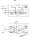
- Fig. 2 is a configuration example thereof.
- a SOC of each of four unit cells 1 connected in series is adjusted, and each of the resistors 2 for adjusting a unit cell SOC and each of FETs (Field-Effect Transistors) 6 embedded in an integrated circuit 5 are connected to each of the four unit cells 1.
- a voltage of each of the unit cells 1 is inputted through each of RC (Resistor-Capacitor) filters each made up of each of resistors 3 and each of capacitors 4 to the unit cell voltage detecting section 7.
- RC Resistor-Capacitor
- the above RC filter is used for noise-reduction and its use is indispensable in HEVs (Hybrid Electric Vehicles) in which much engine spark noise and inverter noise occur particularly, and, in some cases, a LC (Inductor-Capacitor) filter capable of providing more excellent noise-reduction characteristic is employed.
- a bypass control section 8 exercises ON/OFF control on each of the FETs 6 to adjust a SOC of each of the unit cells 1. The SOC adjustment is carried out by an unillustrated upper controller which receives data on a voltage of each of the unit cells 1 from the integrated circuits 5 and which issues a control command to the integrated circuit 5.
- the conventional cell controller when a short occurs among the voltage detecting lines, there is a fear of causing flows of large current, heat generation, smoke generation, ignition, or a like.
- a method is available in which a fuse is inserted to a side of a unit cell of the voltage detecting line.
- the method has a disadvantage that it causes an increase in costs because the fuse has to be connected to all the voltage detecting lines.
- the cell controller is miniaturized by integrating component elements of the SOC adjustment circuit other than the unit cell voltage detecting circuit and resistors for adjusting a voltage into an integrated circuit.
- the cell controller has a problem in that the number of terminals of the integrated circuit is large. The large number of terminals of the integrated circuit causes its package to be made large in size, resulting in increased costs.
- the invention provides a cell controller according to claim 1. Further embodiments of the invention are described in the dependent claims.
- an object of the present invention is to provide a cell controller which is capable of ensuring high safety even when a short occurs among voltage detecting lines without causing increased costs.
- the resistors for SOC adjustment are inserted in series to the voltage detecting lines and the positive electrode and negative electrode of each of the unit cells are connected through each of the voltage detecting lines to the control circuit including the unit cell voltage detecting section, the switching elements or a like. Accordingly, currents flowing due to a short among the voltage detecting lines are limited and safety of the cell controller can be enhanced and, further, the resistors provided originally for SOC adjustment of each of unit cells are used also for a safety measure, thus preventing an increase in costs.
- the unit cell voltage detecting section, switching elements, and control section out of the SOC control section are housed in an integrated circuit
- voltage detecting terminals used for connection of the unit cells to the unit cell voltage detecting section and conducting terminals used for connection of a drain and/or source of the switching element including FETs to the resistors for SOC adjustment are used commonly to reduce the number of the terminals, thereby enabling the reduction of costs for the integrated circuit.
- no bypass currents flow at the time of detecting a voltage of each of the unit cells and no voltage drop caused by the resistors of SOC adjustment occurs, which enables the exact measurement of each of the unit cells.
- the control unit exercises control so that the unit cells whose voltage are to be detected are switched at every predetermined time
- the bypass discharging by the resistors for SOC adjustment is stopped only at a time of detecting a voltage of each of the unit cells by using a simple circuit, for example, an oscillating circuit to detect a voltage of each of the unit cells.
- control section exercises control so that SOC adjustment is not performed simultaneously among unit cells adjacently disposed at higher and lower sides of each of unit cells constituting the battery group, normal conduction of the bypass current can be achieved. That is, if bypass discharging of unit cells adjacently disposed is performed at the same time, since no currents flow through the resistors for SOC adjustment connected to the voltage detecting lines commonly connected and no voltage drop occurs, resulting in the flow of bypass currents being larger than assumed, thus making it difficult to perform normal SOC adjustment of unit cells.
- the control section may exercise control so that the unit cells to be adjusted are switched, at every predetermined time, between odd-numbered unit cells and even-numbered unit cells enumerated from a highest or lowest cell constituting the battery group.
- the unit cell voltage detecting section, switching elements, and control section making up the SOC adjusting section are housed in an integrated circuit.
- all or part of the resistors is preferably located near the unit cells making up the battery group.
- the resistors except the resistors connected to a positive electrode of a highest unit cell and a negative electrode of a lowest unit cell out of the unit cells making up the battery group may be disposed near the unit cells constituting the battery group.
- the cell controller further comprises capacitors connected in parallel through the resistors to each of unit cells making up the battery group, and the resistors and the capacitors function as a RC filter.
- the cell controller can suitably control a battery group operating as a power source for a hybrid electric vehicle.
- the cell controller 10 includes a unit cell voltage detecting section 7 to detect a voltage of each of unit cells 1-1, 1-2, 1-3, and 1-4 making up a battery group through each of voltage detecting lines and a SOC adjusting circuit (SOC adjusting section) for adjusting a SOC of each of the unit cells 1 having SOC adjusting resistors 2-1, 2-2, 2-3, 2-4, and 2-5, FETs 6-1, 6-2, 6-3, and 6-4 serving as a switching element to supply a bypass current to the SOC adjusting resistors 2, and a bypass control section 8 serving as a control unit to exercise on/off control on the FETs 6.
- SOC adjusting section SOC adjusting circuit
- the unit cell voltage detecting section 7, bypass control section 8, and FETs 6 (SOC adjusting circuit excluding the SOC adjusting resisters 2) are housed in the integrated circuit 5.
- the integrated circuit 5 is mounted in the control board 9 making up a main portion of the cell controller 10.
- each of voltage detecting lines routed from each terminal disposed between the highest-positioned unit cell 1 and the lowest-positioned unit cell 1 making up the battery group is connected to each of terminals of the integrated circuits 5 mounted on the control board 5 and power output from the terminals of the unit cells 1 is used as operating power for the integrated circuit 5.
- the start-up power for the integrated circuit 5 may be supplied from any outer unit other than the battery group (for example, from an upper controller operating to control the cell controller).
- the resistors 2 for SOC adjustment are connected in series to the voltage detecting lines. That is, each of the voltage detecting lines routed from the positive and negative electrode of each unit cells 1 is connected to each of terminals of the integrated circuit 5 through each of the resistors 2 for SOC adjustment and, in the integrated circuit 5, each of the terminals of the integrated circuit 5 is connected to the unit cell voltage detecting section 7 and also to each drain of each of the FETs 6 (voltage detecting line routed from each positive electrode of each of the unit cells 1) through each of the resistors 2 for SOC adjustment or each source of the FETs 6 (voltage detecting line routed from each negative electrode of each of the unit cells 1) through each of the resistors 2 for SOC adjustment.
- a gate of each of the FETs 6 is connected to the bypass control section 8 and the FETs 6 are on/off controlled by the bypass control section 8.
- each of capacitors 4-1, 4-2, 4-3, and 4-4 and the capacitors 4 together with the resistors 2 for capacitor adjustment makes up a RC filter for the unit cell voltage detecting section 7.
- the RC filter is inserted into the unit cell voltage detecting section 7 to reduce noise (see Fig. 2 ), however, in this embodiment, the resistors 2 for SOC adjustment serve also as the "R" of the RC filter and, therefore, by selecting a proper capacitor for the "C" of the RC filter, the same frequency characteristics as in the conventional can be obtained.
- the resistors 2-1 and 2-5 for SOC adjustment are mounted on the control board 9 and the resistors 2-2, 2-3, and 2-4 are disposed near the unit cells 1 and connected to the control board 9.
- a unit making up the main control portion may be a CPU (Central Processing Unit) (not shown) mounted in the integrated circuit 5, or a host controller may exert control thereon.
- CPU Central Processing Unit
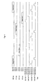
- the bypass control section 8 exercises control so that each of the unit cells 1 whose voltages are to be detected and each of the FETs 6 corresponding to each of the unit cells 1 positioned on the higher and lower sides of each of the unit cells whose voltages are to be detected enter an OFF state. This is for the reason that, by interrupting the bypass current flowing through the resistors 2 for SOC adjustment when a cell voltage is being measured, the unit cell voltage detecting section 7 measures a voltage accurately in a state where no voltage drop caused by the bypass current occurs. By repeating this operation on each of the unit cells 1-1, 1-2, 1-3, and 1-4 in order at every specified time, it is made possible to accurately detect a unit cell voltage in a state in which the bypass currents are interrupted periodically.
- the voltage detection is allowed to be made at appropriate time intervals and, therefore, SOC adjustment of each of unit cells 1 can be performed while the voltage detection is not being made, thus enabling operations to achieve cell balance.
- the bypass control section 8 exerts control while the SOC adjustment is being performed so that each of the FETs 6 corresponding to each of the unit cells 1 to be SOC-adjusted enters an ON state and so that each of the resistors 2 for SOC adjustment connected in series to each of the voltage detecting lines routed from each of the positive and negative electrodes of each of the unit cells to be adjusted and also each of the serially connected resistors 2 for SOC adjustment is connected in parallel to each of the unit cells 1 to be SOC -adjusted.
- Figure 3 shows an operation sequence of each component of the cell controller 10 of the embodiment. As shown in Fig. 3 , by exercising control so as to let the FETs 6 enter an ON state (in the case of no need for the SOC adjustment, an OFF state is maintained) during the period of time described as "Bypass Control", operations of SOC adjustment of each unit cell 1 can be performed while the detection of a voltage is being made.
- control is exercised on the control section side so as not to simultaneously permit the flow of bypass currents for the unit cells being adjacent to each other on the control side.
- control may be exercised so that unit cells to be SOC-adjusted are switched, at every specified time, from unit cells positioned on the upper or lower side to odd-numbered unit cells and even-numbered unit cells.
- Figure 4 shows an operation sequence in this case.
- the control is exercised so that, in every operation of detecting voltages of all unit cells 1, an object to be bypass-controlled is switched to odd-number unit cells and even-numbered unit cells.
- the resistors 2 for SOC adjustment are connected serially to the voltage detecting lines and the positive and negative electrodes of each of the unit cells 1 are connected to the integrated circuit 5 via the voltage detecting lines and, therefore, currents flowing therein are limited even if a short occurs among the voltage detecting lines, thereby increasing safety of the cell controller 10 and, further, the resistors 2 to be originally used for SOC adjustment of each of the unit cells are also employed as a safety measure, thereby preventing an increase in costs.
- the SOC adjusting resistors 2-2, 2-3, and 2-4 are disposed near the unit cells 1 outside the control board 9. Therefore, even when a short occurs among the voltage detecting lines, the flow of currents are limited by the resistors 2, which enables the prevention of smoke generation, ignition, or the like. Also, the SOC adjustment for each of the unit cells 1 is performed by using two resistors 2 for SOC adjustment and, as a result, heat generation of each of the SOC adjusting resistors 2 can be prevented. Moreover, as is apparent from the comparison between Fig. 1 and Fig. 2 , the number of resistors including the resistors 2 for SOC adjustment can be reduced.
- the unit cell voltage detecting section 7, bypass control section 8, and FETs 6 are housed in the integrated circuit 5 and, therefore, the terminals used for the connection to the unit cell voltage detecting circuit and conducting terminals used to connect drains, sources, or the like of the FETs 6 to the SOC adjusting resistors 2 are used commonly, which enables the reduction of the number of terminals to be used, thus decreasing costs for manufacturing the integrated circuit.
- the number of the terminals in the conventional example shown in Fig. 2 is 9, however, the number of the terminals in the embodiment shown in Fig. 1 is successfully reduced to 7.
- the example is shown in which the SOC adjusting resistors 2-1 and 2-5 are mounted on the control board 9, however, the present invention is not limited to this and the SOC adjusting resistors 2-1 and 2-5, as in the case of the SOC adjusting resistors 2-2, 2-3, and 2-4, may be disposed near the unit cells 1 outside the control board 9.
- the present invention has industrial applicability since it provides the cell controller capable of ensuring high safety even when a short occurs among voltage detecting lines without causing increased costs, thus making the cell controller be contributable to its manufacturing and sales.
Landscapes
- Engineering & Computer Science (AREA)
- Power Engineering (AREA)
- Mechanical Engineering (AREA)
- Sustainable Development (AREA)
- Sustainable Energy (AREA)
- Transportation (AREA)
- Life Sciences & Earth Sciences (AREA)
- Manufacturing & Machinery (AREA)
- Chemical & Material Sciences (AREA)
- Chemical Kinetics & Catalysis (AREA)
- Electrochemistry (AREA)
- General Chemical & Material Sciences (AREA)
- Secondary Cells (AREA)
- Charge And Discharge Circuits For Batteries Or The Like (AREA)
Applications Claiming Priority (1)
| Application Number | Priority Date | Filing Date | Title |
|---|---|---|---|
| JP2007188549A JP5060857B2 (ja) | 2007-07-19 | 2007-07-19 | セルコントローラ |
Publications (3)
| Publication Number | Publication Date |
|---|---|
| EP2017939A2 EP2017939A2 (en) | 2009-01-21 |
| EP2017939A3 EP2017939A3 (en) | 2011-01-19 |
| EP2017939B1 true EP2017939B1 (en) | 2016-02-24 |
Family
ID=39876514
Family Applications (1)
| Application Number | Title | Priority Date | Filing Date |
|---|---|---|---|
| EP08153340.8A Active EP2017939B1 (en) | 2007-07-19 | 2008-03-26 | Cell controller |
Country Status (4)
| Country | Link |
|---|---|
| US (1) | US8487590B2 (enExample) |
| EP (1) | EP2017939B1 (enExample) |
| JP (1) | JP5060857B2 (enExample) |
| CN (1) | CN101350531B (enExample) |
Families Citing this family (23)
| Publication number | Priority date | Publication date | Assignee | Title |
|---|---|---|---|---|
| US8823324B2 (en) * | 2008-06-26 | 2014-09-02 | Eveready Battery Company, Inc. | Staggered multi-battery battery charging |
| JP5340676B2 (ja) * | 2008-08-29 | 2013-11-13 | 三洋電機株式会社 | バッテリシステム |
| JP5486822B2 (ja) * | 2009-02-17 | 2014-05-07 | 株式会社日立製作所 | 電池システム |
| JP5221468B2 (ja) | 2009-02-27 | 2013-06-26 | 株式会社日立製作所 | 電池監視装置 |
| JP2010220377A (ja) * | 2009-03-17 | 2010-09-30 | Panasonic Corp | 蓄電装置 |
| DE102010002899A1 (de) | 2010-03-16 | 2011-09-22 | Robert Bosch Gmbh | Verfahren zur Erkennung eines Kurzschlusses nach Batterie-Plus und Schaltungseinrichtung zur Durchführung des Verfahrens |
| JP5618609B2 (ja) * | 2010-04-27 | 2014-11-05 | 日立オートモティブシステムズ株式会社 | 組電池の制御装置 |
| JP5546370B2 (ja) * | 2010-06-28 | 2014-07-09 | 日立ビークルエナジー株式会社 | 蓄電器制御回路及び蓄電装置 |
| JP5645732B2 (ja) * | 2011-03-30 | 2014-12-24 | 株式会社ケーヒン | 電池電圧制御装置 |
| KR20130006077A (ko) * | 2011-07-08 | 2013-01-16 | 삼성전기주식회사 | 전기에너지 저장장치, 그의 전압균등화 모듈 및 전압균등화 방법 |
| JP5606997B2 (ja) * | 2011-07-27 | 2014-10-15 | 株式会社東芝 | 電池セル監視回路、電池セルモジュール、電池セルモジュールを備えた自動車 |
| CN103891093B (zh) | 2011-10-20 | 2016-12-14 | 日立汽车系统株式会社 | 电池系统的监视装置及具备其的蓄电装置 |
| KR101497602B1 (ko) * | 2012-05-02 | 2015-03-03 | 주식회사 엘지화학 | 배터리 밸런싱 시스템 및 이를 이용한 배터리 밸런싱 방법 |
| CN203674739U (zh) * | 2012-11-28 | 2014-06-25 | 东莞赛微微电子有限公司 | 被动式均衡电路 |
| JP5997371B2 (ja) * | 2013-04-26 | 2016-09-28 | 日立オートモティブシステムズ株式会社 | 電池監視装置及びそれを用いた電池システム |
| CN103616557A (zh) * | 2013-10-29 | 2014-03-05 | 广东易事特电源股份有限公司 | 串联蓄电池组单体电池电压检测电路及其检测方法和检测装置 |
| JP6201778B2 (ja) * | 2014-01-17 | 2017-09-27 | 株式会社ケーヒン | 電圧検出装置 |
| JP5744268B1 (ja) * | 2014-03-07 | 2015-07-08 | 東芝エレベータ株式会社 | 蓄電池利用状況監視装置及び蓄電池利用状況監視装置を有するエレベータ |
| US10797939B2 (en) * | 2014-09-05 | 2020-10-06 | Koninklijke Kpn N.V. | WAN control failover broker for vHGW |
| CN105319513A (zh) * | 2015-11-05 | 2016-02-10 | 重庆长安汽车股份有限公司 | 一种汽车电池系统的测试装置 |
| JP6398964B2 (ja) * | 2015-12-15 | 2018-10-03 | 株式会社デンソー | 組電池監視システム |
| JP7325613B2 (ja) * | 2020-03-26 | 2023-08-14 | 三菱電機株式会社 | 電源装置及び組電池充電方法 |
| JP2024067324A (ja) * | 2022-11-04 | 2024-05-17 | プライムプラネットエナジー&ソリューションズ株式会社 | 電池管理装置 |
Family Cites Families (6)
| Publication number | Priority date | Publication date | Assignee | Title |
|---|---|---|---|---|
| JP3670522B2 (ja) * | 1999-07-30 | 2005-07-13 | 富士通株式会社 | バッテリパック |
| JP4168978B2 (ja) | 2004-05-31 | 2008-10-22 | 新神戸電機株式会社 | 組電池用制御回路 |
| JP2006042410A (ja) * | 2004-07-22 | 2006-02-09 | Toshiba Corp | スナバ装置 |
| JP2006078850A (ja) | 2004-09-10 | 2006-03-23 | Canon Inc | カラー画像形成装置 |
| US7759902B2 (en) * | 2005-01-19 | 2010-07-20 | Atmel Corporation | Single chip microcontroller including battery management and protection |
| CA2603912A1 (en) * | 2005-04-05 | 2006-10-12 | Energycs | Multiplexer and switch-based electrochemical cell monitor and management system and method |
-
2007
- 2007-07-19 JP JP2007188549A patent/JP5060857B2/ja active Active
-
2008
- 2008-03-25 US US12/054,890 patent/US8487590B2/en active Active
- 2008-03-26 EP EP08153340.8A patent/EP2017939B1/en active Active
- 2008-03-31 CN CN200810088628.6A patent/CN101350531B/zh active Active
Also Published As
| Publication number | Publication date |
|---|---|
| CN101350531A (zh) | 2009-01-21 |
| US8487590B2 (en) | 2013-07-16 |
| EP2017939A3 (en) | 2011-01-19 |
| CN101350531B (zh) | 2014-09-10 |
| JP2009027839A (ja) | 2009-02-05 |
| JP5060857B2 (ja) | 2012-10-31 |
| US20090021222A1 (en) | 2009-01-22 |
| EP2017939A2 (en) | 2009-01-21 |
Similar Documents
| Publication | Publication Date | Title |
|---|---|---|
| EP2017939B1 (en) | Cell controller | |
| KR101149186B1 (ko) | 충방전 제어 회로 및 충전식 전원 장치 | |
| EP2158659B1 (en) | Rechargeable battery assembly and power system using same | |
| KR102028170B1 (ko) | 셀 밸런싱 회로 및 이를 구비한 배터리 팩 | |
| US8350528B2 (en) | Battery pack and balancing method of battery cells | |
| JP3615507B2 (ja) | 組電池の充電率調整回路 | |
| JP4392103B2 (ja) | 充放電制御回路および充電式電源装置 | |
| CN103038974B (zh) | 高级可再充电蓄电池系统 | |
| CN104917223B (zh) | 电池监视装置 | |
| CN108604715B (zh) | 电池组件和充放电控制方法 | |
| EP2787594A2 (en) | Voltage compensated active cell balancing | |
| US8618806B2 (en) | Circuits and methods for cell number detection | |
| US8400163B2 (en) | Voltage detecting circuit | |
| JP2011259696A (ja) | バッテリ保護回路、その制御方法及びバッテリ・パック | |
| US9863993B2 (en) | Storage battery monitoring device with wiring disconnection detection | |
| JP2005117780A (ja) | 電池用保護icおよびそれを利用した電池パック | |
| KR102046005B1 (ko) | 듀얼 셀 보호 ic 및 이를 포함하는 배터리 모듈 | |
| JP4168978B2 (ja) | 組電池用制御回路 | |
| US20120032513A1 (en) | Battery management circuit, battery module and battery management method | |
| JP4667276B2 (ja) | 複数の二次電池を直列・並列に接続しているパック電池 | |
| RU2563043C2 (ru) | Аккумуляторная батарея для электроинструмента | |
| JP2018117438A (ja) | リチウムイオンキャパシタを備えた電源モジュール | |
| JPH11355966A (ja) | 組電池の充電装置および放電装置 | |
| JP2010011631A (ja) | 電源装置 | |
| TWI379487B (en) | Battery monitoring apparatus and method thereof |
Legal Events
| Date | Code | Title | Description |
|---|---|---|---|
| PUAI | Public reference made under article 153(3) epc to a published international application that has entered the european phase |
Free format text: ORIGINAL CODE: 0009012 |
|
| AK | Designated contracting states |
Kind code of ref document: A2 Designated state(s): AT BE BG CH CY CZ DE DK EE ES FI FR GB GR HR HU IE IS IT LI LT LU LV MC MT NL NO PL PT RO SE SI SK TR |
|
| AX | Request for extension of the european patent |
Extension state: AL BA MK RS |
|
| RIC1 | Information provided on ipc code assigned before grant |
Ipc: H02J 7/00 20060101AFI20081103BHEP Ipc: H01M 10/48 20060101ALI20101028BHEP Ipc: G01R 31/36 20060101ALI20101028BHEP Ipc: B60L 11/18 20060101ALI20101028BHEP |
|
| PUAL | Search report despatched |
Free format text: ORIGINAL CODE: 0009013 |
|
| AK | Designated contracting states |
Kind code of ref document: A3 Designated state(s): AT BE BG CH CY CZ DE DK EE ES FI FR GB GR HR HU IE IS IT LI LT LU LV MC MT NL NO PL PT RO SE SI SK TR |
|
| AX | Request for extension of the european patent |
Extension state: AL BA MK RS |
|
| AKX | Designation fees paid |
Designated state(s): DE FR GB |
|
| 17P | Request for examination filed |
Effective date: 20110928 |
|
| R17P | Request for examination filed (corrected) |
Effective date: 20110719 |
|
| RAP1 | Party data changed (applicant data changed or rights of an application transferred) |
Owner name: HITACHI AUTOMOTIVE SYSTEMS, LTD. |
|
| GRAP | Despatch of communication of intention to grant a patent |
Free format text: ORIGINAL CODE: EPIDOSNIGR1 |
|
| INTG | Intention to grant announced |
Effective date: 20150820 |
|
| GRAS | Grant fee paid |
Free format text: ORIGINAL CODE: EPIDOSNIGR3 |
|
| GRAA | (expected) grant |
Free format text: ORIGINAL CODE: 0009210 |
|
| AK | Designated contracting states |
Kind code of ref document: B1 Designated state(s): DE FR GB |
|
| REG | Reference to a national code |
Ref country code: GB Ref legal event code: FG4D |
|
| REG | Reference to a national code |
Ref country code: DE Ref legal event code: R096 Ref document number: 602008042476 Country of ref document: DE |
|
| REG | Reference to a national code |
Ref country code: FR Ref legal event code: PLFP Year of fee payment: 9 |
|
| REG | Reference to a national code |
Ref country code: DE Ref legal event code: R097 Ref document number: 602008042476 Country of ref document: DE |
|
| PLBE | No opposition filed within time limit |
Free format text: ORIGINAL CODE: 0009261 |
|
| STAA | Information on the status of an ep patent application or granted ep patent |
Free format text: STATUS: NO OPPOSITION FILED WITHIN TIME LIMIT |
|
| GBPC | Gb: european patent ceased through non-payment of renewal fee |
Effective date: 20160524 |
|
| 26N | No opposition filed |
Effective date: 20161125 |
|
| REG | Reference to a national code |
Ref country code: FR Ref legal event code: PLFP Year of fee payment: 10 |
|
| PG25 | Lapsed in a contracting state [announced via postgrant information from national office to epo] |
Ref country code: GB Free format text: LAPSE BECAUSE OF NON-PAYMENT OF DUE FEES Effective date: 20160524 |
|
| REG | Reference to a national code |
Ref country code: FR Ref legal event code: PLFP Year of fee payment: 11 |
|
| REG | Reference to a national code |
Ref country code: DE Ref legal event code: R082 Ref document number: 602008042476 Country of ref document: DE Representative=s name: VIERING, JENTSCHURA & PARTNER MBB PATENT- UND , DE Ref country code: DE Ref legal event code: R081 Ref document number: 602008042476 Country of ref document: DE Owner name: HITACHI ASTEMO, LTD., HITACHINAKA-SHI, JP Free format text: FORMER OWNER: HITACHI AUTOMOTIVE SYSTEMS, LTD., HITACHINAKA-SHI, IBARAKI, JP |
|
| PGFP | Annual fee paid to national office [announced via postgrant information from national office to epo] |
Ref country code: DE Payment date: 20250128 Year of fee payment: 18 |
|
| PGFP | Annual fee paid to national office [announced via postgrant information from national office to epo] |
Ref country code: FR Payment date: 20250210 Year of fee payment: 18 |