EP2017666A1 - Thermooptische Vorrichtung und Steuerungsverfahren - Google Patents
Thermooptische Vorrichtung und Steuerungsverfahren Download PDFInfo
- Publication number
- EP2017666A1 EP2017666A1 EP08104798A EP08104798A EP2017666A1 EP 2017666 A1 EP2017666 A1 EP 2017666A1 EP 08104798 A EP08104798 A EP 08104798A EP 08104798 A EP08104798 A EP 08104798A EP 2017666 A1 EP2017666 A1 EP 2017666A1
- Authority
- EP
- European Patent Office
- Prior art keywords
- heater
- optical
- optical waveguide
- region
- detector
- Prior art date
- Legal status (The legal status is an assumption and is not a legal conclusion. Google has not performed a legal analysis and makes no representation as to the accuracy of the status listed.)
- Ceased
Links
- 238000000034 method Methods 0.000 title claims description 26
- 230000003287 optical effect Effects 0.000 claims abstract description 140
- 238000001514 detection method Methods 0.000 claims abstract description 21
- 239000004065 semiconductor Substances 0.000 claims description 47
- 125000006850 spacer group Chemical group 0.000 claims description 4
- 230000010355 oscillation Effects 0.000 description 9
- 238000001228 spectrum Methods 0.000 description 7
- 230000015556 catabolic process Effects 0.000 description 6
- 238000006731 degradation reaction Methods 0.000 description 6
- 239000000463 material Substances 0.000 description 5
- VYPSYNLAJGMNEJ-UHFFFAOYSA-N Silicium dioxide Chemical compound O=[Si]=O VYPSYNLAJGMNEJ-UHFFFAOYSA-N 0.000 description 4
- 230000007257 malfunction Effects 0.000 description 4
- 230000001902 propagating effect Effects 0.000 description 4
- 239000013078 crystal Substances 0.000 description 3
- 238000004519 manufacturing process Methods 0.000 description 3
- 230000000694 effects Effects 0.000 description 2
- 230000007613 environmental effect Effects 0.000 description 2
- 239000000377 silicon dioxide Substances 0.000 description 2
- 238000010521 absorption reaction Methods 0.000 description 1
- BJQHLKABXJIVAM-UHFFFAOYSA-N bis(2-ethylhexyl) phthalate Chemical compound CCCCC(CC)COC(=O)C1=CC=CC=C1C(=O)OCC(CC)CCCC BJQHLKABXJIVAM-UHFFFAOYSA-N 0.000 description 1
- 230000003247 decreasing effect Effects 0.000 description 1
- 238000010438 heat treatment Methods 0.000 description 1
- 238000002347 injection Methods 0.000 description 1
- 239000007924 injection Substances 0.000 description 1
Images


Classifications
-
- G—PHYSICS
- G02—OPTICS
- G02F—OPTICAL DEVICES OR ARRANGEMENTS FOR THE CONTROL OF LIGHT BY MODIFICATION OF THE OPTICAL PROPERTIES OF THE MEDIA OF THE ELEMENTS INVOLVED THEREIN; NON-LINEAR OPTICS; FREQUENCY-CHANGING OF LIGHT; OPTICAL LOGIC ELEMENTS; OPTICAL ANALOGUE/DIGITAL CONVERTERS
- G02F1/00—Devices or arrangements for the control of the intensity, colour, phase, polarisation or direction of light arriving from an independent light source, e.g. switching, gating or modulating; Non-linear optics
- G02F1/01—Devices or arrangements for the control of the intensity, colour, phase, polarisation or direction of light arriving from an independent light source, e.g. switching, gating or modulating; Non-linear optics for the control of the intensity, phase, polarisation or colour
- G02F1/0147—Devices or arrangements for the control of the intensity, colour, phase, polarisation or direction of light arriving from an independent light source, e.g. switching, gating or modulating; Non-linear optics for the control of the intensity, phase, polarisation or colour based on thermo-optic effects
-
- H—ELECTRICITY
- H01—ELECTRIC ELEMENTS
- H01S—DEVICES USING THE PROCESS OF LIGHT AMPLIFICATION BY STIMULATED EMISSION OF RADIATION [LASER] TO AMPLIFY OR GENERATE LIGHT; DEVICES USING STIMULATED EMISSION OF ELECTROMAGNETIC RADIATION IN WAVE RANGES OTHER THAN OPTICAL
- H01S5/00—Semiconductor lasers
- H01S5/06—Arrangements for controlling the laser output parameters, e.g. by operating on the active medium
- H01S5/0607—Arrangements for controlling the laser output parameters, e.g. by operating on the active medium by varying physical parameters other than the potential of the electrodes, e.g. by an electric or magnetic field, mechanical deformation, pressure, light, temperature
- H01S5/0612—Arrangements for controlling the laser output parameters, e.g. by operating on the active medium by varying physical parameters other than the potential of the electrodes, e.g. by an electric or magnetic field, mechanical deformation, pressure, light, temperature controlled by temperature
-
- G—PHYSICS
- G02—OPTICS
- G02F—OPTICAL DEVICES OR ARRANGEMENTS FOR THE CONTROL OF LIGHT BY MODIFICATION OF THE OPTICAL PROPERTIES OF THE MEDIA OF THE ELEMENTS INVOLVED THEREIN; NON-LINEAR OPTICS; FREQUENCY-CHANGING OF LIGHT; OPTICAL LOGIC ELEMENTS; OPTICAL ANALOGUE/DIGITAL CONVERTERS
- G02F1/00—Devices or arrangements for the control of the intensity, colour, phase, polarisation or direction of light arriving from an independent light source, e.g. switching, gating or modulating; Non-linear optics
- G02F1/01—Devices or arrangements for the control of the intensity, colour, phase, polarisation or direction of light arriving from an independent light source, e.g. switching, gating or modulating; Non-linear optics for the control of the intensity, phase, polarisation or colour
- G02F1/0121—Operation of devices; Circuit arrangements, not otherwise provided for in this subclass
-
- G—PHYSICS
- G02—OPTICS
- G02F—OPTICAL DEVICES OR ARRANGEMENTS FOR THE CONTROL OF LIGHT BY MODIFICATION OF THE OPTICAL PROPERTIES OF THE MEDIA OF THE ELEMENTS INVOLVED THEREIN; NON-LINEAR OPTICS; FREQUENCY-CHANGING OF LIGHT; OPTICAL LOGIC ELEMENTS; OPTICAL ANALOGUE/DIGITAL CONVERTERS
- G02F1/00—Devices or arrangements for the control of the intensity, colour, phase, polarisation or direction of light arriving from an independent light source, e.g. switching, gating or modulating; Non-linear optics
- G02F1/29—Devices or arrangements for the control of the intensity, colour, phase, polarisation or direction of light arriving from an independent light source, e.g. switching, gating or modulating; Non-linear optics for the control of the position or the direction of light beams, i.e. deflection
- G02F1/31—Digital deflection, i.e. optical switching
- G02F1/313—Digital deflection, i.e. optical switching in an optical waveguide structure
- G02F1/3136—Digital deflection, i.e. optical switching in an optical waveguide structure of interferometric switch type
-
- G—PHYSICS
- G02—OPTICS
- G02F—OPTICAL DEVICES OR ARRANGEMENTS FOR THE CONTROL OF LIGHT BY MODIFICATION OF THE OPTICAL PROPERTIES OF THE MEDIA OF THE ELEMENTS INVOLVED THEREIN; NON-LINEAR OPTICS; FREQUENCY-CHANGING OF LIGHT; OPTICAL LOGIC ELEMENTS; OPTICAL ANALOGUE/DIGITAL CONVERTERS
- G02F2201/00—Constructional arrangements not provided for in groups G02F1/00 - G02F7/00
- G02F2201/30—Constructional arrangements not provided for in groups G02F1/00 - G02F7/00 grating
- G02F2201/307—Reflective grating, i.e. Bragg grating
-
- G—PHYSICS
- G02—OPTICS
- G02F—OPTICAL DEVICES OR ARRANGEMENTS FOR THE CONTROL OF LIGHT BY MODIFICATION OF THE OPTICAL PROPERTIES OF THE MEDIA OF THE ELEMENTS INVOLVED THEREIN; NON-LINEAR OPTICS; FREQUENCY-CHANGING OF LIGHT; OPTICAL LOGIC ELEMENTS; OPTICAL ANALOGUE/DIGITAL CONVERTERS
- G02F2201/00—Constructional arrangements not provided for in groups G02F1/00 - G02F7/00
- G02F2201/34—Constructional arrangements not provided for in groups G02F1/00 - G02F7/00 reflector
- G02F2201/346—Constructional arrangements not provided for in groups G02F1/00 - G02F7/00 reflector distributed (Bragg) reflector
-
- H—ELECTRICITY
- H01—ELECTRIC ELEMENTS
- H01S—DEVICES USING THE PROCESS OF LIGHT AMPLIFICATION BY STIMULATED EMISSION OF RADIATION [LASER] TO AMPLIFY OR GENERATE LIGHT; DEVICES USING STIMULATED EMISSION OF ELECTROMAGNETIC RADIATION IN WAVE RANGES OTHER THAN OPTICAL
- H01S5/00—Semiconductor lasers
- H01S5/02—Structural details or components not essential to laser action
- H01S5/024—Arrangements for thermal management
- H01S5/02407—Active cooling, e.g. the laser temperature is controlled by a thermo-electric cooler or water cooling
- H01S5/02415—Active cooling, e.g. the laser temperature is controlled by a thermo-electric cooler or water cooling by using a thermo-electric cooler [TEC], e.g. Peltier element
-
- H—ELECTRICITY
- H01—ELECTRIC ELEMENTS
- H01S—DEVICES USING THE PROCESS OF LIGHT AMPLIFICATION BY STIMULATED EMISSION OF RADIATION [LASER] TO AMPLIFY OR GENERATE LIGHT; DEVICES USING STIMULATED EMISSION OF ELECTROMAGNETIC RADIATION IN WAVE RANGES OTHER THAN OPTICAL
- H01S5/00—Semiconductor lasers
- H01S5/02—Structural details or components not essential to laser action
- H01S5/026—Monolithically integrated components, e.g. waveguides, monitoring photo-detectors, drivers
- H01S5/0261—Non-optical elements, e.g. laser driver components, heaters
-
- H—ELECTRICITY
- H01—ELECTRIC ELEMENTS
- H01S—DEVICES USING THE PROCESS OF LIGHT AMPLIFICATION BY STIMULATED EMISSION OF RADIATION [LASER] TO AMPLIFY OR GENERATE LIGHT; DEVICES USING STIMULATED EMISSION OF ELECTROMAGNETIC RADIATION IN WAVE RANGES OTHER THAN OPTICAL
- H01S5/00—Semiconductor lasers
- H01S5/06—Arrangements for controlling the laser output parameters, e.g. by operating on the active medium
- H01S5/0617—Arrangements for controlling the laser output parameters, e.g. by operating on the active medium using memorised or pre-programmed laser characteristics
-
- H—ELECTRICITY
- H01—ELECTRIC ELEMENTS
- H01S—DEVICES USING THE PROCESS OF LIGHT AMPLIFICATION BY STIMULATED EMISSION OF RADIATION [LASER] TO AMPLIFY OR GENERATE LIGHT; DEVICES USING STIMULATED EMISSION OF ELECTROMAGNETIC RADIATION IN WAVE RANGES OTHER THAN OPTICAL
- H01S5/00—Semiconductor lasers
- H01S5/06—Arrangements for controlling the laser output parameters, e.g. by operating on the active medium
- H01S5/068—Stabilisation of laser output parameters
- H01S5/0683—Stabilisation of laser output parameters by monitoring the optical output parameters
- H01S5/0687—Stabilising the frequency of the laser
-
- H—ELECTRICITY
- H01—ELECTRIC ELEMENTS
- H01S—DEVICES USING THE PROCESS OF LIGHT AMPLIFICATION BY STIMULATED EMISSION OF RADIATION [LASER] TO AMPLIFY OR GENERATE LIGHT; DEVICES USING STIMULATED EMISSION OF ELECTROMAGNETIC RADIATION IN WAVE RANGES OTHER THAN OPTICAL
- H01S5/00—Semiconductor lasers
- H01S5/10—Construction or shape of the optical resonator, e.g. extended or external cavity, coupled cavities, bent-guide, varying width, thickness or composition of the active region
- H01S5/12—Construction or shape of the optical resonator, e.g. extended or external cavity, coupled cavities, bent-guide, varying width, thickness or composition of the active region the resonator having a periodic structure, e.g. in distributed feedback [DFB] lasers
- H01S5/1206—Construction or shape of the optical resonator, e.g. extended or external cavity, coupled cavities, bent-guide, varying width, thickness or composition of the active region the resonator having a periodic structure, e.g. in distributed feedback [DFB] lasers having a non constant or multiplicity of periods
- H01S5/1209—Sampled grating
-
- H—ELECTRICITY
- H01—ELECTRIC ELEMENTS
- H01S—DEVICES USING THE PROCESS OF LIGHT AMPLIFICATION BY STIMULATED EMISSION OF RADIATION [LASER] TO AMPLIFY OR GENERATE LIGHT; DEVICES USING STIMULATED EMISSION OF ELECTROMAGNETIC RADIATION IN WAVE RANGES OTHER THAN OPTICAL
- H01S5/00—Semiconductor lasers
- H01S5/10—Construction or shape of the optical resonator, e.g. extended or external cavity, coupled cavities, bent-guide, varying width, thickness or composition of the active region
- H01S5/12—Construction or shape of the optical resonator, e.g. extended or external cavity, coupled cavities, bent-guide, varying width, thickness or composition of the active region the resonator having a periodic structure, e.g. in distributed feedback [DFB] lasers
- H01S5/125—Distributed Bragg reflector [DBR] lasers
Definitions
- the present invention relates an optical device and a method of controlling the optical device.
- a wavelength-tunable semiconductor laser is an example of an optical device.
- the wavelength-tunable semiconductor laser has a gain for a laser oscillation and selects wavelength.
- Such a method of tuning the refractive index does not need a mechanical movable portion, being different from a method of tuning a mechanical angle or a mechanical length. It therefore has an advantage in reliability and manufacturing cost.
- a semiconductor laser having a Sampled Grating Distributed Bragg Reflector (SG-DBR) in which the peak wavelength of the reflection peak ranges periodically and a Sampled Grating Distributed Feedback (SG-DFB), in which the peak wavelength of the gain spectrum ranges periodically, as a concrete example of a wavelength-tunable laser adopting a method of tuning the temperature of an optical waveguide.
- SG-DBR Sampled Grating Distributed Bragg Reflector
- SG-DFB Sampled Grating Distributed Feedback
- This semiconductor laser controls the correlation between the reflection spectra of the SG-DBR and the SG-DFB, selects a wavelength with a Vernier effect, and emits laser light. That is, the semiconductor laser oscillates at one of the wavelengths where two spectra overlap and the reflection intensity gets biggest. It is therefore possible to control the oscillation wavelength by controlling the correlation of two reflection spectra.
- Document 1 discloses a semiconductor laser controlling an oscillation wavelength with the control of refractive index of an optical waveguide.
- a heater is adopted as a control portion of the refractive index of the optical waveguide.
- the wavelength is controlled with temperature control of the optical waveguide using the heater.
- Degradation of the heater is a problem where the heater is used for a control of the refractive index of the optical waveguide.
- the heat value of the heater changes even if a constant current is provided to the heater, because the resistance of the heater changes as a result of the degradation of the heater.
- temperature differential between each optical waveguide is important and the unexpected changing of the heat value is fatal, in an optical device that has a combination of the optical waveguides having wavelength properties different from each other, such as a combination of the SG-DFB and the SG-DBR.
- the width of the temperature range ( ⁇ T) of the heater for controlling the temperature of the optical waveguide is approximately 40 degrees.
- the temperature of the heater is relatively low. Therefore, the degradation of the heater has not been considered.
- the detection result of the temperature detection element is ideal because the detection result includes a changing of the temperature caused by temperature changes in the environment and by degradation of the heater.
- the present invention has been made in view of the above circumstances and aims to provide an optical device that obtains a desired optical property even if a heater is degraded, and a method of controlling the optical device.
- an optical device including an optical element, a detector and a controller.
- the optical element has an optical waveguide.
- the refractive index of the optical waveguide is controlled by a heater.
- the temperature of the optical element is controlled by a temperature control device.
- the detector detects the current flowing in the heater and/or the voltage applied to the heater.
- the controller controls the electrical power provided to the heater so as to keep it constant according to the detection result of the detector.
- the temperature changing of the optical device is restrained by the use of the temperature control device. That is, the temperature of the optical waveguide is substantially determined by the heat value of the heater, because the temperature changes in the optical device caused by environmental changes may be neglected.
- the heat value of the heater is determined by the electrical power provided to the heater. In this case, the heat value is stabilized when the amount of the electrical power of the heater is kept constant.
- the present invention controls the temperature of the optical element with use of the temperature control device in order substantially to determine the temperature of the optical waveguide in view of the above circumstances. Also, the current flowing in the heater and/or the voltage applied to the heater is detected in order to determine the amount of the electrical power of the heater. According to the present invention, the amount of the electrical power of the heater is determined and the heater is controlled with the amount of the electrical power. Therefore, the heat value may be kept constant even if the heater is degraded. Moreover a desirable optical property may be obtained.
- a method of controlling an optical device including: controlling the temperature of an optical semiconductor element with a temperature control device; controlling the refractive index of the optical semiconductor device with a heater; and controlling the electrical power provided to the heater so as to keep it constant according to a current flowing in the heater and/or a voltage applied to the heater.
- the temperature change in the optical semiconductor element is restrained with the use of the temperature control device. Further, the heat value of the heater may be stabilized, because the electrical power provided to the heater is controlled to be kept constant. In this case, a desired optical property may be obtained even if the heater is degraded.
- FIG. 1 illustrates a semiconductor laser 10 in accordance with a first embodiment and a structure of a laser device 100 having the semiconductor laser 10.
- the laser device 100 has the semiconductor laser 10, a temperature control device 20, a wavelength detector 30, an output detector 40 and a controller 50.
- the semiconductor laser 10 is mounted on the temperature control device 20.
- a description will be given of each part.
- the semiconductor laser 10 has a structure in which a SG-DBR region 11, a SG-DFB region 12 and a semiconductor amplifier (SOA: Semiconductor Optical Amplifier) region 13 are coupled in order.
- the SG-DBR region 11 has an optical waveguide in which gratings are provided at a given interval. That is, the optical waveguide of the SG-DBR region 11 has a first region that has a diffraction grating and a second region that is optically connected to the first region and acts as a spacer.
- the optical waveguide of the SG-DBR region 11 is composed of semiconductor crystal having an absorption edge wavelength on the shorter-wavelength side compared to the laser oscillation wavelength.
- a heater 14 is provided on the SG-DBR region 11.
- the SG-DFB region 12 has an optical waveguide in which gratings are provided at a given interval. That is, the optical waveguide of the SG-DFB region 12 has a first region that has a grating and a second region that is optically connected to the first region and acts as a spacer.
- the optical waveguide of the SG-DFB region 12 is composed of a semiconductor crystal amplifying light of a desired wavelength of a laser oscillation.
- An electrode 15 is provided on the SG-DFB region 12.
- the SOA region 13 is composed of semiconductor crystal for amplifying light or for absorbing light with a current control.
- An electrode 16 is provided on the SOA region 13.
- the optical waveguides of the SG-DBR region 11, the SG-DFB region 12 and the SOA region 13 are optically connected to each other.
- the laser device 100 has a voltage detector 17 detecting the voltage applied to the heater 14.
- the semiconductor laser 10 and a thermistor are mounted on the temperature control device 20.
- the wavelength detector 30 has a light-receiving element for detecting the intensity of lasing light and a light-receiving element for detecting the intensity of lasing light that passes through an etalon and has wavelength property.
- the output detector 40 has a light-receiving element for detecting the intensity of lasing light passing through the SOA region 13.
- the wavelength detector 30 is arranged on the side of the SG-DBR region 11, and the output detector 40 is arranged on the side of the SOA region 13.
- the structure of the laser device 100 is not limited. For example, each of the detectors may be arranged in reverse.
- the controller 50 has a control portion having a central processing unit (CPU), a random-access memory (RAM), a read-only memory (ROM) and so on, and an electrical power supply.
- the ROM of the controller 50 stores control information and a control program for the semiconductor laser 10.
- the control information is, for example, stored in a look-up table 51.
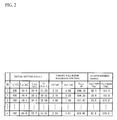
- FIG. 2 illustrates an example of the look-up table 51.
- the look-up table 51 includes an initial setting value, a target value for feedback control, and an alarm setting range in every channel.
- the initial setting value includes an initial current value I LD of the SG-DFB region 12, an initial current value I SOA of the SOA region 13, an initial current value I Heater of the heater 14 and the initial temperature value T LD of the temperature control device 20.
- the target value for the feedback control includes a target value Im1 for feedback control of the output detector 40, a target value Im3/Im2 for feedback control of the wavelength detector 30 and a target electrical power value P Heater for feedback control of the heater 14.
- the alarm setting range includes a resistance R heater (minimum) that is a minimum resistance of the heater 14 and a maximum resistance R Heater (maximum) of the heater 14.
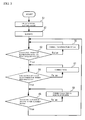
- FIG. 3 illustrates a flowchart showing a controlling method of the laser device 100.
- the controller 50 refers to the look-up table 51 and obtains the initial current value I LD , the initial current value I SOA , the initial current value I Heater and the initial temperature value T LD (Step S1).
- the controller 50 starts a laser oscillation of the semiconductor laser 10 according to the initial setting value obtained in Step S1 (Step S2).
- the controller 50 controls the temperature control device 20 so that the temperature of the temperature control device 20 takes on the initial temperature value T LD .
- the temperature of the semiconductor laser 10 is controlled to be constant near the initial temperature value T LD . Consequently the equivalent refractive index of the optical waveguide of the SG-DFB region 12 is controlled to be a given value.
- the controller 50 provides a current of the initial current value I Heater to the heater 14. Therefore, the equivalent refractive index of the optical waveguide of the SG-DBR region 11 is controlled to be a given value.
- the controller 50 provides a current of the initial current value I LD to the electrode 15. Also, light is generated in the optical waveguide of the SG-DFB region 12. The light generated in the SG-DFB region 12 is repeatedly reflected and amplified in the optical waveguide of the SG-DBR region 11 and the SG-DFB region 12. This results in a laser oscillation. Then, the controller 50 provides a current of the initial current value I SOA to the electrode 16. With these sequences, the semiconductor laser 10 emits a lasing light at an initial wavelength corresponding to a set channel.
- the controller 50 determines whether the wavelength of the lasing light is within a required range according to the detection result of the wavelength detector 30 (Step S3).
- the controller 50 obtains the target value Im3/Im2 for feedback control from the look-up table 51, obtains a ratio Im3/Im2 of the two light-receiving elements in the wavelength detector 30 and determines whether the ratio Im3/Im2 is within a given range including the target value Im3/Im2 for feedback control.
- Step S6 the controller 50 corrects the temperature of the temperature control device 20 (Step S6). In this case, the peak wavelength of a gain spectrum in the optical waveguide in the SG-DFB region 12 changes. After that, the controller 50 executes Step S3 again. With the loop, the wavelength of the lasing light is feedback-controlled to be kept at a desired constant value.
- Step S4 the controller 50 determines whether the optical intensity of the lasing light is within a required range.
- the controller 50 obtains the target value Im1 for feedback control from the look-up table 51, obtains the detection result Im1 of the light-receiving element in the output detector 40, and determines whether the detection result Im1 is within a given range including the target value Im1 for feedback control.
- Step S4 If it is not determined that the optical intensity of the lasing light is within the required range in Step S4, the controller 50 corrects the current provided to the electrode 16 (Step S7). After that, the controller 50 executes Step S4 again. With the loop, the optical intensity of the lasing light is feedback-controlled to be a desired constant value.
- Step S5 the controller 50 determines whether the electrical power provided to the heater 14 is within a required range.
- the controller 50 obtains the target value P Heater for feedback control from the look-up table 51, and calculates the electrical power provided to the heater 14 with the detection result of the voltage detector 17 and the current value provided to the heater 14. The controller 50 determines whether the calculated value is within a required range including the target value P Heater for feedback control.
- Step S8 the controller 50 corrects the electrical power provided to the heater 14 (Step S8).
- the electrical power may be corrected by changing at least one of the current and the voltage.
- the controller 50 corrects the electrical power by increasing and decreasing the current value provided to the heater 14. With the loop, the electrical power provided to the heater 14 is feedback-controlled so that the electrical power provided to the heater 14 is kept a desired constant value. If it is determined that the electrical power provided to the heater 14 is within the required range in Step S5, the controller 50 executes Step S3 again.
- the temperature change of the semiconductor laser 10 is restrained by the use of the temperature control device 20. Further, the heat value of the heater 14 is stabilized even if the resistance of the heater 14 changes because of degradation thereof, because the electrical power provided to the heater 14 is controlled to be kept constant. In this case, a temperature differential between the SG-DBR region 11 and the SG-DFB region 12 is kept constant. Therefore, the semiconductor laser 10 oscillates at a desired wavelength even if the heater 14 has deteriorated.
- the voltage detector 17 detects the voltage applied to the heater 14, and the current provided to the heater 14 is controlled to be a given value. It is therefore possible to monitor the changing resistance of the heater 14 with the voltage value and the current value. In this case, it is possible to determine a malfunction of the heater 14 and a possibility or likelihood of a malfunction.
- the controller 50 may warn a user of the malfunction in the case where the electrical resistance obtained from the detection result of the voltage detector 17 is over the resistance R Heater (maximum). In this case, it is possible to send an alert to a user to exchange the semiconductor laser 10.
- the alert of the breaking or malfunction is effective for both time degradation of the heater 14 and a sudden environmental change.
- the heater is subjected to an unexpected stress because of a production tolerance, usage environment or the like, because a heater is provided on a micro area of a tunable laser such as the semiconductor laser 10.
- the controller 50 may warn a user when the electrical resistance of the heater 14 is under the resistance R Heater (minimum). In this case, an excessive current is prevented from being provided to the heater 14.
- FIG. 4 illustrates details of the voltage detector 17.
- the voltage detector 17 includes a voltmeter 18, a first terminal TVh and a second terminal TVhg.
- the first terminal TVh is connected to a first end of the heater 14 and the second terminal TVhg is connected to the second end of the heater 14.
- a driving current from the controller 50 is provided to the first end of the heater 14 from a terminal TIh, and is grounded through a terminal TIg from the second end of the heater 14.
- the heater driving current does not flow between the terminal TVh and the terminal TVhg.
- the voltage drop caused by the resistance of such as a terminal or a wire thus is prevented from affecting the detection result of the voltmeter 18. It is therefore possible to detect the voltage applied to the heater 14 accurately.
- the semiconductor laser has a combination of the SG-DBR region and the SG-DFB region.
- the present invention may be applied to a semiconductor laser in which an active region acting as a gain region is between a pair of SG-DBR regions.
- a heater is provided on each of the SG-DBR regions, or on one of the SG-DBR regions. In this case, it is possible to control using feedback so that the electrical power provided to the heater is kept constant, if the voltage applied to the heater is detected by the voltage detector 17.
- the present invention may be applied to a CSG-DBR (Chirped Sampled Grating Distributed Bragg Reflector).
- CSG-DBR Cold Sampled Grating Distributed Bragg Reflector
- space regions connecting gratings have a different length from each other, being different from the SG-DBR region. Therefore, there is wavelength dependence in a peak intensity of a reflection spectrum of the CSG-DBR region. In this case, the peak intensity of the reflection spectrum is enlarged in a given wavelength range. It is therefore possible to restrain oscillation at a wavelength other than a desired wavelength, if a wavelength in a wavelength range having relatively high intensity is used as a lasing wavelength.
- the semiconductor laser 10 corresponds to the optical element
- the voltage detector 17 corresponds to the detector
- the SG-DFB region 12 corresponds to the active region
- the SG-DBR region 11 corresponds to the optical waveguide.
- FIG. 5 illustrates a semiconductor laser 10a and the structure of a laser device 100a having the semiconductor laser 10a.
- the semiconductor laser 10a has a CSG-DBR region 11a instead of the SG-DBR region 11.
- the CSG-DBR region 11a has three segments forming a combination of a grating and a spacer region. Accordingly, three heaters 14a, 14b and 14c are provided on the CSG-DBR region 11a according to each of the segments. Moreover, voltage detectors 17a, 17b and 17c are provided according to each of the heaters.
- the semiconductor laser 10a obtains a desired oscillation wavelength.
- the number of gratings and heaters in the CSG-DBR region is not limited. Other parts of the device can be similar to the first embodiment.
- the present invention may be applied to an optical element other than a semiconductor laser.
- the present invention may be applied to a Mach-Zehnder optical switch.
- This optical switch is used in an exchange system such as an optical cross-connect.
- FIG. 6 illustrates a structure of an optical switch 200 in accordance with a third embodiment.
- the optical switch 200 is made of a material having a thermo-optical effect such as silica-based material.
- the optical switch 200 has a Mach-Zehnder interference structure having a first waveguide 201 and a second waveguide 202.
- the optical switch 200 is arranged on a temperature control device 210. Therefore, the temperature control device 210 controls the temperature of each part of the switch.
- the optical switch 200 has a heater 203.
- the heater 203 heats the second waveguide 202. This results in a changing of the phase differential between light propagating in the first waveguide 201 and light propagating in the second waveguide 202.
- the optical switch 200 selects a cross condition or a bar condition of the optical signal of the first waveguide 201 and the second waveguide 202.
- the heater 203 is connected to a voltage detector 204.
- the voltage detector 204 detects the voltage applied to the heater 203, and gives the detection result to a controller 220.
- the controller 220 controls the temperature control device 210 so that the temperature of the optical switch 200 is kept at a given temperature, and the controller 220 controls the electrical power provided to the heater 203 in feedback so as to keep it constant, according to the detection result of the voltage detector 204.
- the heat value of the heater 203 is thus kept constant even if the heater 203 is degraded. Therefore, the phase differential between the light propagating in the first waveguide 201 and the light propagating in the second waveguide 202 is kept constant. Consequently, the switching reliability of the optical switch 200 is improved.
- the optical switch 200 corresponds to the optical element
- the voltage detector 204 corresponds to the detector
- the optical switch 200, the voltage detector 204 and the controller 220 correspond to the optical device.
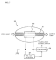
- FIG. 7 illustrates a top view of the main part of an optical waveguide 300 in accordance with a fourth embodiment.
- the optical waveguide 300 has a buried hetero-structure.
- a heater 302 is provided on an optical waveguide core 301.
- the optical waveguide core 301 simply transmits light. Therefore, the optical waveguide core 301 does not have an optical structure such as a diffraction grating.
- the optical waveguide 300 is arranged on a temperature control device (not shown). The temperature control device controls the temperature of the entire area of the optical waveguide 300.
- the optical waveguide core 301 is made of a thermo-optical material such as silica-based material or semiconductor material such as GaInAsP or AlGaInAs.
- a voltage detector 303 is connected to the heater 302. The voltage detector 303 detects the voltage applied to the heater 302 and gives the detected result to a controller 304. The controller 304 controls the electrical power provided to the heater 302, according to the detected result of the voltage detector 303.
- the optical length of the optical waveguide core 301 differs from its designed optical length because of a production tolerance.
- the tolerance causes the phase of a light signal passing through the optical waveguide core 301 to be different from a designed value.
- the heater 302 is provided for control of the phase of laser light passing through the optical waveguide core 301.
- the temperature of the optical waveguide core 301 is controlled with the heating of the heater 302, and the optical length of the optical waveguide core 301 is finely controlled.
- the heat value of the heater 302 is stabilized if the electrical power provided to the heater 302 is controlled to be kept constant, even if the heater is degraded. This results in a highly accurate control.
- the optical waveguide 300 may be applied to a Mach-Zehnder optical switch.
- an optical length differential between two waveguides may be controlled with a heater.
- a voltmeter detects the voltage applied to a heater.
- the structure is not limited to this.
- a current meter may detect the current provided to the heater, and the electrical power may be controlled by controlling the voltage applied to the heater.
- an electrical power meter may detect the electrical power provided to the heater and the electrical power may be controlled by controlling the current provided to the heater and/or the voltage applied to the heater.
Landscapes
- Physics & Mathematics (AREA)
- General Physics & Mathematics (AREA)
- Optics & Photonics (AREA)
- Nonlinear Science (AREA)
- Condensed Matter Physics & Semiconductors (AREA)
- Electromagnetism (AREA)
- Semiconductor Lasers (AREA)
Applications Claiming Priority (2)
| Application Number | Priority Date | Filing Date | Title |
|---|---|---|---|
| JP2007188879 | 2007-07-19 | ||
| JP2008179731A JP2009044141A (ja) | 2007-07-19 | 2008-07-10 | 光学デバイスおよびその制御方法 |
Publications (1)
| Publication Number | Publication Date |
|---|---|
| EP2017666A1 true EP2017666A1 (de) | 2009-01-21 |
Family
ID=39832514
Family Applications (1)
| Application Number | Title | Priority Date | Filing Date |
|---|---|---|---|
| EP08104798A Ceased EP2017666A1 (de) | 2007-07-19 | 2008-07-18 | Thermooptische Vorrichtung und Steuerungsverfahren |
Country Status (2)
| Country | Link |
|---|---|
| US (1) | US7812594B2 (de) |
| EP (1) | EP2017666A1 (de) |
Cited By (1)
| Publication number | Priority date | Publication date | Assignee | Title |
|---|---|---|---|---|
| EP2234224A3 (de) * | 2009-03-27 | 2013-12-25 | Furukawa Electric Co., Ltd. | Lichtquelle mit variabler Wellenlänge |
Families Citing this family (9)
| Publication number | Priority date | Publication date | Assignee | Title |
|---|---|---|---|---|
| JP4856216B2 (ja) * | 2008-09-25 | 2012-01-18 | 富士通株式会社 | 光通信装置及び同光通信装置の制御装置並びに光出力安定化方法 |
| JP2011142584A (ja) * | 2010-01-08 | 2011-07-21 | Fujitsu Optical Components Ltd | 光伝送装置 |
| JP5488159B2 (ja) | 2010-04-20 | 2014-05-14 | 住友電気工業株式会社 | 定電力制御回路 |
| JP2014013823A (ja) * | 2012-07-04 | 2014-01-23 | Sumitomo Electric Ind Ltd | 波長可変半導体レーザの制御方法 |
| JP2013089754A (ja) * | 2011-10-18 | 2013-05-13 | Sumitomo Electric Ind Ltd | 波長可変半導体レーザの制御方法 |
| CN103441992B (zh) * | 2013-08-14 | 2017-02-15 | 青岛海信宽带多媒体技术有限公司 | 一种保证光模块协议数据完整性的方法 |
| JP6308089B2 (ja) * | 2013-09-30 | 2018-04-11 | 住友電気工業株式会社 | 光半導体装置の制御方法 |
| CN105572437B (zh) * | 2014-10-16 | 2018-07-20 | 鸿劲科技股份有限公司 | 电子组件测试装置及其应用的测试设备 |
| JP2016100380A (ja) * | 2014-11-19 | 2016-05-30 | 富士通オプティカルコンポーネンツ株式会社 | レーザ装置、及び、光送信機 |
Citations (4)
| Publication number | Priority date | Publication date | Assignee | Title |
|---|---|---|---|---|
| JPH0829813A (ja) | 1994-07-13 | 1996-02-02 | Nippon Telegr & Teleph Corp <Ntt> | 熱光学効果光スイッチ駆動装置 |
| JP2003149610A (ja) | 2001-11-12 | 2003-05-21 | Hitachi Cable Ltd | 導波路型光可変減衰器 |
| EP1753104A2 (de) * | 2005-08-11 | 2007-02-14 | Eudyna Devices Inc. | Halbleiterlaser |
| EP1804349A1 (de) | 2005-12-27 | 2007-07-04 | Eudyna Devices Inc. | Halbleiterlaser mit Tastgitter mit DFB und DBR beinhaltend Phasensprünge |
Family Cites Families (3)
| Publication number | Priority date | Publication date | Assignee | Title |
|---|---|---|---|---|
| JP2914248B2 (ja) | 1995-09-23 | 1999-06-28 | 日本電気株式会社 | 波長可変半導体レーザ素子 |
| JP2001298413A (ja) * | 2000-04-12 | 2001-10-26 | Sumitomo Electric Ind Ltd | 光adm装置 |
| JP3819347B2 (ja) * | 2002-09-05 | 2006-09-06 | 富士写真フイルム株式会社 | 放射線像変換パネル |
-
2008
- 2008-07-17 US US12/174,948 patent/US7812594B2/en active Active
- 2008-07-18 EP EP08104798A patent/EP2017666A1/de not_active Ceased
Patent Citations (4)
| Publication number | Priority date | Publication date | Assignee | Title |
|---|---|---|---|---|
| JPH0829813A (ja) | 1994-07-13 | 1996-02-02 | Nippon Telegr & Teleph Corp <Ntt> | 熱光学効果光スイッチ駆動装置 |
| JP2003149610A (ja) | 2001-11-12 | 2003-05-21 | Hitachi Cable Ltd | 導波路型光可変減衰器 |
| EP1753104A2 (de) * | 2005-08-11 | 2007-02-14 | Eudyna Devices Inc. | Halbleiterlaser |
| EP1804349A1 (de) | 2005-12-27 | 2007-07-04 | Eudyna Devices Inc. | Halbleiterlaser mit Tastgitter mit DFB und DBR beinhaltend Phasensprünge |
Cited By (2)
| Publication number | Priority date | Publication date | Assignee | Title |
|---|---|---|---|---|
| EP2234224A3 (de) * | 2009-03-27 | 2013-12-25 | Furukawa Electric Co., Ltd. | Lichtquelle mit variabler Wellenlänge |
| US8743920B2 (en) | 2009-03-27 | 2014-06-03 | Furukawa Electric Co., Ltd. | Wavelength variable light source system |
Also Published As
| Publication number | Publication date |
|---|---|
| US20090021238A1 (en) | 2009-01-22 |
| US7812594B2 (en) | 2010-10-12 |
Similar Documents
| Publication | Publication Date | Title |
|---|---|---|
| EP2017666A1 (de) | Thermooptische Vorrichtung und Steuerungsverfahren | |
| EP2017927B1 (de) | Verfahren zur Steuerung eines Halbleiterlasers | |
| EP2017928B1 (de) | Verfahren zur Steuerung eines Halbleiterlasers | |
| US20100296532A1 (en) | Laser device and laser device control data | |
| US7929581B2 (en) | Testing method of wavelength-tunable laser, controlling method of wavelength-tunable laser and laser device | |
| EP2362505B1 (de) | Verfahren zur Steuerung eines wellenlängenabstimmbaren Lasers | |
| CN101350496B (zh) | 光器件及其控制方法 | |
| US8279907B2 (en) | Semiconductor laser device and method for controlling semiconductor laser | |
| JP2009044024A (ja) | 半導体レーザ装置、および半導体レーザの制御方法 | |
| JP2019087572A (ja) | 波長可変光源、及び光半導体装置 | |
| JP7214498B2 (ja) | 波長可変レーザ装置及びマルチモード発振検知方法 | |
| US8681826B2 (en) | Method for tuning semiconductor laser | |
| EP1741169A1 (de) | Wellenlängenregelung von laserlicht | |
| JP2005101039A (ja) | 波長可変レーザ、波長可変レーザアレイ素子ならびにそれらの制御方法 | |
| JP2024114192A (ja) | 波長可変レーザ装置、及び波長可変レーザ装置の波長制御方法 | |
| JP2012156558A (ja) | 半導体レーザ装置の制御方法 |
Legal Events
| Date | Code | Title | Description |
|---|---|---|---|
| PUAI | Public reference made under article 153(3) epc to a published international application that has entered the european phase |
Free format text: ORIGINAL CODE: 0009012 |
|
| AK | Designated contracting states |
Kind code of ref document: A1 Designated state(s): AT BE BG CH CY CZ DE DK EE ES FI FR GB GR HR HU IE IS IT LI LT LU LV MC MT NL NO PL PT RO SE SI SK TR |
|
| AX | Request for extension of the european patent |
Extension state: AL BA MK RS |
|
| 17P | Request for examination filed |
Effective date: 20090715 |
|
| AKX | Designation fees paid |
Designated state(s): DE FR GB |
|
| 17Q | First examination report despatched |
Effective date: 20130816 |
|
| STAA | Information on the status of an ep patent application or granted ep patent |
Free format text: STATUS: THE APPLICATION HAS BEEN REFUSED |
|
| 18R | Application refused |
Effective date: 20160215 |