EP2017632B1 - Verfahren zur Fehlererkennung in unkompensierten Stromleitungen mit unsynchronisierter Zwei-Enden-Messung - Google Patents
Verfahren zur Fehlererkennung in unkompensierten Stromleitungen mit unsynchronisierter Zwei-Enden-Messung Download PDFInfo
- Publication number
- EP2017632B1 EP2017632B1 EP07460017A EP07460017A EP2017632B1 EP 2017632 B1 EP2017632 B1 EP 2017632B1 EP 07460017 A EP07460017 A EP 07460017A EP 07460017 A EP07460017 A EP 07460017A EP 2017632 B1 EP2017632 B1 EP 2017632B1
- Authority
- EP
- European Patent Office
- Prior art keywords
- fault
- sinh
- cosh
- line
- positive sequence
- Prior art date
- Legal status (The legal status is an assumption and is not a legal conclusion. Google has not performed a legal analysis and makes no representation as to the accuracy of the status listed.)
- Not-in-force
Links
- 238000000034 method Methods 0.000 title claims abstract description 31
- 238000005259 measurement Methods 0.000 title abstract description 14
- 230000005540 biological transmission Effects 0.000 claims abstract description 13
- 238000010586 diagram Methods 0.000 claims description 8
- 238000004590 computer program Methods 0.000 claims description 6
- 208000002925 dental caries Diseases 0.000 claims description 3
- 238000004364 calculation method Methods 0.000 description 19
- 238000004422 calculation algorithm Methods 0.000 description 3
- 230000001419 dependent effect Effects 0.000 description 2
- 230000001360 synchronised effect Effects 0.000 description 2
- 230000006866 deterioration Effects 0.000 description 1
- 229920006395 saturated elastomer Polymers 0.000 description 1
Images

Classifications
-
- G—PHYSICS
- G01—MEASURING; TESTING
- G01R—MEASURING ELECTRIC VARIABLES; MEASURING MAGNETIC VARIABLES
- G01R31/00—Arrangements for testing electric properties; Arrangements for locating electric faults; Arrangements for electrical testing characterised by what is being tested not provided for elsewhere
- G01R31/08—Locating faults in cables, transmission lines, or networks
- G01R31/088—Aspects of digital computing
Definitions
- the present invention is concerned with a method for fault location in uncompensated power lines with two- end unsynchronized measurement, finding an application in the power industry and for overhead and overhead-cable transmission or distribution lines.
- the presented invention is characterized by the steps of, after the occurrence of a fault along the section, calculating a distance from A end or B end to the fault dependent on a fault current measured at one of said first and second ends and phase voltages measured at both of said first and second ends A and B, where the distance to fault is calculated from the end A or B where the fault is measured.
- the invention is particularly suitable when a current transformer at either of the first A or second ends B is saturated. If so , then a distance to a fault is calculated dependent on a fault current measured at the non -affected end and phase voltages measured at both the affected end and non-affected end.
- a method for locating a fault in two-terminal power transmission or distribution line comprises the steps of receiving measurements of the three phase currents from both terminals, receiving measurements of the three phase voltages from one line terminal , receiving parameters of the line and receiving the fault type. Base on this information the distance to fault from the one terminal where the phase voltages were measured is determined and output. Since only the phase voltages of the line terminal are needed, the functionality of a device , in particular a current differential relay can be expended to determine the distance to fault in an off-line mode.
- the essence of the inventive method for locating faults in a section of at least one transmission line consist of the following:
- the advantage of the method according to the invention is the overcoming of all the limitations and drawbacks of the known methods.
- the iterative calculations are completely avoided and the distributed parameter line model is considered from the very beginning. Simplicity of calculations is assured by simultaneous use of two kinds of symmetrical components of the measured voltage and current signals. Such simultaneous use of two kinds of symmetrical components of the measured voltage and current signals is not applied in any other known fault location technique.
- the present invention is characterized by use of very simple calculations (solution of the quadratic formula for complex numbers) and at the same time the distributed parameter line model is strictly, i.e.
- the synchronization angle is determined accurately, with strict considering the distributed parameter line model, what allows accurate analytical synchronization of the measurements acquired asynchronously. Then, the distance to fault is calculated as in case of using synchronized measurements. Therefore, the accuracy of fault location according to the invented method is at the same level as in case of using the synchronized measurements. As a result of that, the GPS synchronization is not required for the invented method and there is no deterioration in the fault location accuracy at all.
- fig.1 presents a general diagram of the electric network for the implementation of the inventive method
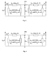
- fig.2 an equivalent circuit diagram for a distributed parameter model of the transmission line A-B under the fault at point F, for the positive sequence
- fig.3 an equivalent circuit diagram for a distributed parameter model of the transmission line A-B under the fault at point F, for negative sequence
- fig.4 an equivalent circuit diagram for a distributed parameter model of the transmission line A-B under the fault at point F, for the incremental positive sequence
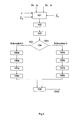
- fig.5 - shows a flow-chart of the example of a fault locations algorithm according to the present invention.
- the electric network for the implementation of the inventive method is presented in the fig.1 .
- the network has two terminals A, at the beginning of the line and B at the end of the line. Between the terminals, along the length l of the line, at the distance to fault d from the line terminal A the fault point F is located.
- the fault locator FL is located at terminal A, however it can be also located at terminal B, or as a stand-alone device not associated with the line terminals, what is not depicted on the drawing.
- the method according to the invention can be realized as it is depicted in the fig.5 in the following steps.
- the digital phasor data of three phase voltages V A and three phase currents I A from terminal A and digital phasor data of three phase voltages V B and three phase currents I B from terminal B, impedance Z ' 1L and admittance Y ' 1L of the line for the positive sequence, line length /, and fault type in terms whether it is unbalanced or three-phase balanced fault, are delivered as the input data of the fault locator FL .
- Step 102
- V ⁇ F ⁇ 1 A V ⁇ A ⁇ 1 ⁇ e j ⁇ ⁇ cosh ⁇ ⁇ 1 ⁇ L l - Z ⁇ c ⁇ 1 ⁇ L ⁇ I ⁇ A ⁇ 1 ⁇ e j ⁇ ⁇ sinh ⁇ ⁇ 1 ⁇ L l d where:
- this step it is determined whether the fault is a three phase balanced fault or unbalanced fault based on the input data, the subroutine I, for the positive and negative sequence quantities and a distributed parameter line model or the subroutine II for the positive and incremental positive sequence quantities and a distributed parameter line model is run.
- V ⁇ F ⁇ 2 A V ⁇ A ⁇ 2 ⁇ e j ⁇ ⁇ cosh ⁇ ⁇ 1 ⁇ L l d - Z ⁇ c ⁇ 1 ⁇ L ⁇ I ⁇ A ⁇ 2 ⁇ e j ⁇ ⁇ sinh ⁇ ⁇ 1 ⁇ L l d .
- V A2 , I A2 - phasors of the negative sequence voltage and currents measured at the substation A.
- V ⁇ F ⁇ 2 A V ⁇ F ⁇ 2 B .
- G ⁇ 2 ⁇ e j ⁇ + H ⁇ 2 ⁇ cosh ⁇ ⁇ 1 ⁇ L l d + S ⁇ 2 ⁇ e j ⁇ + T ⁇ 2 ⁇ sinh ⁇ ⁇ 1 ⁇ L l d 0
- G ⁇ 2 G ⁇ A ⁇ 2
- H ⁇ 2 Z ⁇ c ⁇ 1 ⁇ L ⁇ sinh ⁇ ⁇ 1 ⁇ L l ⁇ I ⁇ B ⁇ 2 - cosh ⁇ ⁇ 1 ⁇ L l ⁇ V ⁇ B ⁇ 2
- S ⁇ 2 - Z ⁇ c ⁇ 1 ⁇ L ⁇ I ⁇ A ⁇ 2
- T ⁇ 2 sinh ⁇ ⁇ 1 ⁇ L l ⁇ V ⁇ B ⁇ 2 - Z ⁇ c
- B ⁇ 5 G ⁇ 3 ⁇ S ⁇ ⁇ ⁇ 1 - G ⁇ ⁇ ⁇ 1 ⁇ S ⁇ 3
- B ⁇ 4 G 3 ⁇ T ⁇ ⁇ ⁇ 1 + H ⁇ 3 ⁇ S ⁇ ⁇ ⁇ 1 - G ⁇ ⁇ ⁇ 1 ⁇ T ⁇ 3 - H ⁇ ⁇ ⁇ 1 ⁇ S ⁇ 3
- B ⁇ 3 H ⁇ 3 ⁇ T ⁇ ⁇ ⁇ 1 - H ⁇ ⁇ ⁇ 1 ⁇ T ⁇ 3 .
- a computer program product comprising computer program code which when executed on a computing device caries out the steps of a method according to any of the claims 1-2.
Landscapes
- Physics & Mathematics (AREA)
- Engineering & Computer Science (AREA)
- Mathematical Physics (AREA)
- Theoretical Computer Science (AREA)
- General Physics & Mathematics (AREA)
- Emergency Protection Circuit Devices (AREA)
- Locating Faults (AREA)
- Testing Of Short-Circuits, Discontinuities, Leakage, Or Incorrect Line Connections (AREA)
Claims (3)
- Verfahren zur Fehlererkennung in unkompensierten Stromleitungen mit unsynchronisierter Zwei-Ende-Messung, bestehend aus:- einer Messung von Spannungs- und Stromwerten an beiden Enden (A) und (B) des Abschnitts,- Erlangung des Phasors der koinzidenten Spannungskomponenten ( V A1, V B1), die jeweils an den Enden (A) und (B) gemessen werden,- Erlangung des Phasors der koinzidenten Stromkomponenten ( I A1, I B1) die jeweils an den Enden (A) und (B) gemessen werden,- Feststellung, ob ein dreipoliger Kurzschluss vorliegt oder nicht, dadurch gekennzeichnet dass- wenn kein dreipoliger Kurzschluss vorliegt, beginnt die Tätigkeit für die koinzidenten und die gegensätzlichen symmetrischen Komponenten sowie ein lineares Modell mit verteilten Parametern gemäß der Unterprozedur I, die durch folgende Schritte definiert ist:- Erlangung des Phasors der gegensätzlichen Spannungskomponenten ( V A2, V B2), die jeweils an den Enden (A) und (B) gemessen werden,- Erlangung des Phasors der gegensätzlichen Stromkomponenten ( I A2 I B2), die jeweils an den Enden (A) und (B) gemessen werden,- Verwendung eines gleichwertigen Schaltschemas für die koinzidenten und gegensätzlichen Komponenten sowie eines linearen Modells mit verteilten Parametern, Feststellung des Synchronisierungswinkels (δ), der als Synchronisierungsoperator (ejδ) gemäß nachstehender Formel bestimmt wird:wobei:


 - durch Auflösung der quadratischen Gleichung B 2[ejδ]2 + B 1ejδ + B 0 = 0 ergeben sich somit zwei Lösungen (ejδ
1 ) und (ejδ2 ),- wobei man (ejδoder man (ejδ1 ) als gültiges Ergebnis für den Synchronisationsoperator (ejδ) wählt, wenn die folgende Beziehung |1-|ejδ1 ∥<|1-|ejδ2 ∥ erfüllt ist,2 ) als gültiges Ergebnis für den Synchronisationsoperator (ejδ) wählt, wenn die folgende Beziehung |1-|ejδ1 ∥>|1-|ejδ2 ∥ erfüllt ist,- die gültige Lösung (ejδ) wird zur Bestimmung der Entfernung (d) zur Fehlerstellegemäß folgender Formel verwendet:
wobei:ℓ die Länge der Leitung,
 Z ' 1L die Impedanz der Leitung für die koinzidente Komponente,Y ' 1L die Admittanz der Leitung für die koinzidente Komponente ist;ejδ das gültige Ergebnis für den Synchronisationsparameter bezeichnet, das als ejδ
1 oder ejδ2 gewählt wurde,- wenn ein dreipoliger Kurzschluss vorliegt, beginnt die Tätigkeit für die koinzidenten symmetrischen und die koinzidenten inkremetalen Komponenten sowie ein lineares Modell mit verteilten Parametern gemäß der Unterprozedur II, die durch folgende Schritte definiert ist:- Erlangung des Phasors der inkrementalen koinzidenten Spannungskomponenten ( V AΔ1, V BΔ1), die jeweils an den Enden (A) und (B) gemessen werden,- Erlangung des Phasors der inkrementalen koinzidenten Stromkomponenten ( I AΔ1, I BΔ1), die jeweils an den Enden (A) und (B) gemessen werden,- Verwendung eines gleichwertigen Schaltschemas für die koinzidenten und die inkrementalen koinzidenten Komponenten sowie eines linearen Modells mit verteilten Parametern, Feststellung des Synchronisierungswinkels (δ), der als Synchronisierungsoperator (ejδ) gemäß nachstehender Formel bestimmt wird:wobei: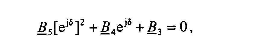


 - durch Auflösung der quadratischen Gleichung B 5[ejδ]2 + B 4ejδ + B 3 = 0 ergeben sich somit zwei Lösungen (ejδ
3 ) and (ejδ4 ),- wobei man (ejδ3 ) als gültiges Ergebnis für den Synchronisationsoperator (ejδ) wählt, wenn die folgende Beziehung |1-|ejδ3 ∥<|1-|ejδ4 ∥ erfüllt ist,
oder man (ejδ4 ) als gültiges Ergebnis für den Synchronisationsoperator (ejδ) wählt, wenn die folgende Beziehung |1-|ejδ3 ∥>|1-|ejδ4 ∥ erfüllt ist,- die gültige Lösung (ejδ) wird zur Bestimmung der Entfernung (d) zur Fehlerstelle gemäß folgender Formel verwendet:wobei: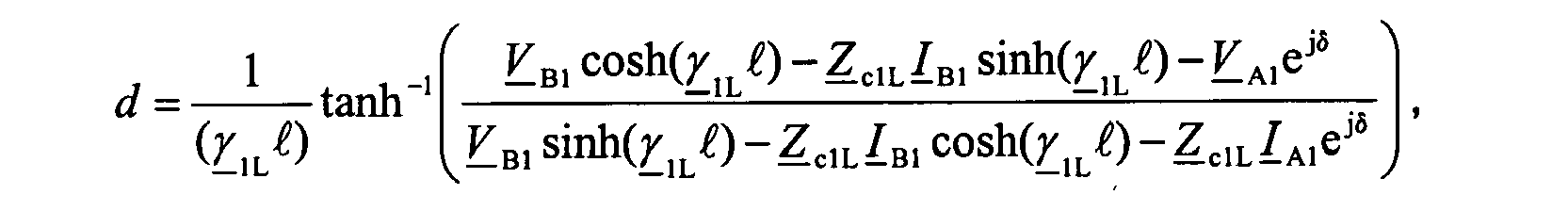 ℓ die Länge der Leitung,
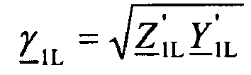
 Z ' 1L die Impedanz der Leitung für die koinzidente Komponente,Y ' 1L die Admittanz der Leitung für die koinzidente Komponente ist;ejδ das gültige Ergebnis für den Synchronisationsparameter bezeichnet, das als ejδ
3 oder ejδ4 gewählt wurde. - Schutzrelais, das mit einem Fehlererkennungsgerät (FL) ausgestattet ist, welches die Mittel zur Erfüllung der Ansprüche gemäß Pkt. 1 besitzt.
- Produkt in Form eines Computerprogramms, das den Programmcode enthält, der bei Anwendung in der Computereinrichtung die Schritte des Verfahrens nach Anspruch 1 ausführt.
Priority Applications (9)
| Application Number | Priority Date | Filing Date | Title |
|---|---|---|---|
| DE602007008715T DE602007008715D1 (de) | 2007-07-19 | 2007-07-19 | Verfahren zur Fehlererkennung in unkompensierten Stromleitungen mit unsynchronisierter Zwei-Enden-Messung |
| AT07460017T ATE479103T1 (de) | 2007-07-19 | 2007-07-19 | Verfahren zur fehlererkennung in unkompensierten stromleitungen mit unsynchronisierter zwei-enden- messung |
| ES07460017T ES2351478T3 (es) | 2007-07-19 | 2007-07-19 | Procedimiento para localizar fallos en líneas eléctricas descompensadas con medición no sincronizada en dos extremos. |
| EP07460017A EP2017632B1 (de) | 2007-07-19 | 2007-07-19 | Verfahren zur Fehlererkennung in unkompensierten Stromleitungen mit unsynchronisierter Zwei-Enden-Messung |
| BRPI0812679A BRPI0812679A2 (pt) | 2007-07-19 | 2008-06-23 | método para localização de falha em linhas de potência descompensadas com medição não sincronizada em duas extremidades. |
| CN2008800252132A CN101779134B (zh) | 2007-07-19 | 2008-06-23 | 用双端非同步测量在非补偿电力线路中定位故障的方法 |
| US12/669,502 US8207743B2 (en) | 2007-07-19 | 2008-06-23 | Method for fault location in uncompensated power lines with two-end unsynchronized measurement |
| RU2010105848/28A RU2010105848A (ru) | 2007-07-19 | 2008-06-23 | Способ определения места повреждения на неуравновешенных линиях электропередачи с несинхронизированным измерением на двух концах |
| PCT/EP2008/005223 WO2009010169A1 (en) | 2007-07-19 | 2008-06-23 | Method for fault location in uncompensated power lines with two-end unsynchronized measurement |
Applications Claiming Priority (1)
| Application Number | Priority Date | Filing Date | Title |
|---|---|---|---|
| EP07460017A EP2017632B1 (de) | 2007-07-19 | 2007-07-19 | Verfahren zur Fehlererkennung in unkompensierten Stromleitungen mit unsynchronisierter Zwei-Enden-Messung |
Publications (2)
| Publication Number | Publication Date |
|---|---|
| EP2017632A1 EP2017632A1 (de) | 2009-01-21 |
| EP2017632B1 true EP2017632B1 (de) | 2010-08-25 |
Family
ID=38823816
Family Applications (1)
| Application Number | Title | Priority Date | Filing Date |
|---|---|---|---|
| EP07460017A Not-in-force EP2017632B1 (de) | 2007-07-19 | 2007-07-19 | Verfahren zur Fehlererkennung in unkompensierten Stromleitungen mit unsynchronisierter Zwei-Enden-Messung |
Country Status (9)
| Country | Link |
|---|---|
| US (1) | US8207743B2 (de) |
| EP (1) | EP2017632B1 (de) |
| CN (1) | CN101779134B (de) |
| AT (1) | ATE479103T1 (de) |
| BR (1) | BRPI0812679A2 (de) |
| DE (1) | DE602007008715D1 (de) |
| ES (1) | ES2351478T3 (de) |
| RU (1) | RU2010105848A (de) |
| WO (1) | WO2009010169A1 (de) |
Families Citing this family (29)
| Publication number | Priority date | Publication date | Assignee | Title |
|---|---|---|---|---|
| ES2351478T3 (es) | 2007-07-19 | 2011-02-07 | Abb Research Ltd. | Procedimiento para localizar fallos en líneas eléctricas descompensadas con medición no sincronizada en dos extremos. |
| BRPI0901107A2 (pt) * | 2009-03-05 | 2010-01-19 | Reason Tecnologia S A | mÉtodo e mecanismo para identificaÇço, registro e armazenamento de frentes de ondas viajantes em sistemas de energia elÉtrica |
| RU2526095C2 (ru) * | 2009-10-09 | 2014-08-20 | Александр Никандорович Висящев | Способ определения места повреждения на воздушных линиях электропередачи (варианты) |
| US8558551B2 (en) | 2010-04-21 | 2013-10-15 | Schweitzer Engineering Laboratories Inc | Fault location in electric power delivery systems |
| US8525522B2 (en) | 2010-04-21 | 2013-09-03 | Schweitzer Engineering Laboratories Inc | Fault location in electric power delivery systems |
| US8942954B2 (en) * | 2010-09-16 | 2015-01-27 | Schweitzer Engineering Laboratories, Inc. | Fault location in a non-homogeneous electric power line |
| WO2012037947A1 (en) * | 2010-09-20 | 2012-03-29 | Technische Universität Dortmund | Method and system for fault detection on an electrical power transmission line |
| CN102116821A (zh) * | 2010-12-14 | 2011-07-06 | 山东省电力学校 | 基于工频相量的输电线路故障点的定位方法 |
| US8803461B2 (en) * | 2010-12-22 | 2014-08-12 | Arvind Kumar Tiwari | System and method for synchronous machine health monitoring |
| US8791704B2 (en) | 2011-10-11 | 2014-07-29 | Schweitzer Engineering Laboratories Inc. | Fault-type identification for electric power delivery systems |
| RU2505826C2 (ru) * | 2012-01-11 | 2014-01-27 | Общество с ограниченной ответственностью "Исследовательский центр "Бреслер" | Способ определения места и характера повреждения многопроводной электрической сети |
| RU2505827C1 (ru) * | 2012-05-23 | 2014-01-27 | Федеральное государственное бюджетное образовательное учреждение высшего профессионального образования "Иркутский государственный технический университет" (ФГБОУ ВПО "ИрГТУ") | Способ определения места короткого замыкания на воздушной линии электропередачи по замерам с двух ее концов (варианты) |
| RU2504792C1 (ru) * | 2012-07-17 | 2014-01-20 | Федеральное государственное бюджетное образовательное учреждение высшего профессионального образования "Национальный исследовательский Томский политехнический университет" | Способ определения места короткого замыкания на воздушной линии электропередачи по массивам мгновенных значений токов и напряжений |
| RU2508556C1 (ru) * | 2012-10-24 | 2014-02-27 | Федеральное государственное бюджетное образовательное учреждение высшего профессионального образования "Иркутский государственный технический университет" (ФГБОУ ВПО "ИрГТУ") | Способ определения места короткого замыкания на воздушной линии электропередачи при несинхронизированных замерах с двух ее концов |
| RU2540443C1 (ru) * | 2013-07-23 | 2015-02-10 | Федеральное государственное бюджетное образовательное учреждение высшего профессионального образования "Национальный исследовательский Томский политехнический университет" | Способ определения места обрыва на воздушной линии электропередачи |
| RU2586438C1 (ru) * | 2015-04-29 | 2016-06-10 | Степан Георгиевич Тигунцев | Способ определения места короткого замыкания на длинной линии электропередачи напряжением 220 кв и выше |
| RU2593409C1 (ru) * | 2015-07-13 | 2016-08-10 | Степан Георгиевич Тигунцев | Способ определения места короткого замыкания на длинной линии электропередачи с отпайкой |
| RU2610826C1 (ru) * | 2015-09-22 | 2017-02-15 | Федеральное Государственное Бюджетное Образовательное Учреждение Высшего Образования "Ростовский Государственный Университет Путей Сообщения"(Фгбоу Во Ргупс) | Способ определения удаленности короткого замыкания контактной сети (варианты) |
| CN105259474A (zh) * | 2015-10-30 | 2016-01-20 | 中国南方电网有限责任公司电网技术研究中心 | 一种t接电缆的在线故障测距方法 |
| RU2620193C1 (ru) * | 2015-12-18 | 2017-05-23 | Степан Георгиевич Тигунцев | Способ определения места короткого замыкания на воздушной линии электропередачи с распределенными параметрами |
| RU2610852C1 (ru) * | 2015-12-18 | 2017-02-16 | федеральное государственное бюджетное образовательное учреждение высшего образования "Иркутский национальный исследовательский технический университет" (ФГБОУ ВО "ИРНИТУ") | Способ определения места короткого замыкания на воздушной линии электропередачи с выполнением расчетной синхронизации измерений с двух её концов |
| RU2640091C2 (ru) * | 2016-05-04 | 2017-12-26 | федеральное государственное бюджетное образовательное учреждение высшего образования "Нижегородский государственный технический университет им. Р.Е. Алексеева" (НГТУ) | Способ определения места обрыва на воздушной линии электропередачи по массивам мгновенных значений токов и напряжений |
| EP3732759A1 (de) * | 2017-12-29 | 2020-11-04 | ABB Power Grids Switzerland AG | Fehlerortung in abzweigleitungen mit mehreren anschlüssen |
| EP3776778B1 (de) | 2018-03-31 | 2023-10-11 | Hitachi Energy Switzerland AG | Verfahren und vorrichtung zum schutz in einem leistungsübertragungssystem mit mehreren endgeräten |
| EP3605765A1 (de) | 2018-07-31 | 2020-02-05 | ABB Schweiz AG | Identifizierung eines fehlerhaften abschnitts der stromübertragungsleitung |
| CN109241626B (zh) * | 2018-09-07 | 2022-05-17 | 福建水利电力职业技术学院 | 一种输电线路工频序参数的计算方法 |
| US10859639B2 (en) | 2018-10-02 | 2020-12-08 | Schweitzer Engineering Laboratories, Inc. | Fault-type identification in an electric power delivery system using composite signals |
| CN114002544B (zh) * | 2021-10-11 | 2024-03-08 | 北京四方继保工程技术有限公司 | 一种多端线路保护故障定位及测距的方法 |
| CN114047408B (zh) * | 2022-01-17 | 2022-03-29 | 广东电网有限责任公司佛山供电局 | 一种输电线路高精度故障测距方法及相关装置 |
Family Cites Families (10)
| Publication number | Priority date | Publication date | Assignee | Title |
|---|---|---|---|---|
| SE433405B (sv) * | 1982-09-14 | 1984-05-21 | Asea Ab | Forfarande och anordning for lokalisering av ett felstelle pa en trefasig kraftledning |
| US5455776A (en) * | 1993-09-08 | 1995-10-03 | Abb Power T & D Company Inc. | Automatic fault location system |
| JP2000214210A (ja) * | 1999-01-20 | 2000-08-04 | Toshiba Corp | 事故点標定装置 |
| CN1100997C (zh) * | 2000-09-15 | 2003-02-05 | 清华大学 | 输电线路故障点定位方法及装置 |
| CN1138329C (zh) * | 2000-11-08 | 2004-02-11 | 华中科技大学 | 电力线路保护与故障定位方法及用于该方法的行波传感器 |
| SE519943C2 (sv) | 2000-12-14 | 2003-04-29 | Abb Ab | Metod för fellokalisering i en transmissionlinje |
| SE524866C2 (sv) | 2001-11-23 | 2004-10-12 | Abb Ab | Metod och anordning för fellokalisering genom användande av mätningar från två ändar av en luftledning för transmission av växelström |
| US7286963B2 (en) * | 2005-12-30 | 2007-10-23 | Abb Technology Ltd. | Method and device for fault location on three terminal power line |
| SE528863C2 (sv) | 2006-01-12 | 2007-02-27 | Abb Technology Ltd | Metod och anordning för fellokalisering vid en krafttransmissions- eller distributionsledning med två terminaler |
| ES2351478T3 (es) | 2007-07-19 | 2011-02-07 | Abb Research Ltd. | Procedimiento para localizar fallos en líneas eléctricas descompensadas con medición no sincronizada en dos extremos. |
-
2007
- 2007-07-19 ES ES07460017T patent/ES2351478T3/es active Active
- 2007-07-19 DE DE602007008715T patent/DE602007008715D1/de active Active
- 2007-07-19 AT AT07460017T patent/ATE479103T1/de not_active IP Right Cessation
- 2007-07-19 EP EP07460017A patent/EP2017632B1/de not_active Not-in-force
-
2008
- 2008-06-23 US US12/669,502 patent/US8207743B2/en not_active Expired - Fee Related
- 2008-06-23 BR BRPI0812679A patent/BRPI0812679A2/pt not_active IP Right Cessation
- 2008-06-23 WO PCT/EP2008/005223 patent/WO2009010169A1/en active Application Filing
- 2008-06-23 CN CN2008800252132A patent/CN101779134B/zh not_active Expired - Fee Related
- 2008-06-23 RU RU2010105848/28A patent/RU2010105848A/ru not_active Application Discontinuation
Also Published As
| Publication number | Publication date |
|---|---|
| ES2351478T3 (es) | 2011-02-07 |
| EP2017632A1 (de) | 2009-01-21 |
| CN101779134B (zh) | 2013-02-20 |
| RU2010105848A (ru) | 2011-08-27 |
| CN101779134A (zh) | 2010-07-14 |
| BRPI0812679A2 (pt) | 2019-09-24 |
| ATE479103T1 (de) | 2010-09-15 |
| WO2009010169A1 (en) | 2009-01-22 |
| DE602007008715D1 (de) | 2010-10-07 |
| US20110037480A1 (en) | 2011-02-17 |
| US8207743B2 (en) | 2012-06-26 |
Similar Documents
| Publication | Publication Date | Title |
|---|---|---|
| EP2017632B1 (de) | Verfahren zur Fehlererkennung in unkompensierten Stromleitungen mit unsynchronisierter Zwei-Enden-Messung | |
| EP2201393B1 (de) | Verfahren zur fehlerlokalisierung auf reihenkompensierten stromübertragungsleitungen mit zweiendiger unsynchronisierter messung | |
| EP1992954B1 (de) | Verfahren zur Ortung eines einpoligen Erdschlusses | |
| Saha et al. | A new accurate fault locating algorithm for series compensated lines | |
| RU2397503C2 (ru) | Способ для определения места повреждения линий электропередачи | |
| US7298149B2 (en) | Fault location using measurements of current and voltage from one end of a line | |
| US8183871B2 (en) | Method and device for fault location in a two-terminal transmission or distribution power line | |
| EP1172660B9 (de) | Verfahren und Vorrichtung zur Fehlerortung in Versorgungsnetzen | |
| CN101344567B (zh) | 用于确定相对地故障位置的方法 | |
| EP0665441A2 (de) | Verfahren zum Lokalisieren des Ortes eines Fehlers auf einer Energieübertragungsleitung | |
| EP1870717B1 (de) | System und Verfahren zur Bestimmung von Phase-Erde-Admittanzen einer Dreiphasenleitung | |
| EP1739441B1 (de) | Verfahren und System zur Ortung eines einpoligen Erdschlusses | |
| EP3482472B1 (de) | Verfahren und system zur ortung eines fehlers in einer gemischten energieübertragungsleitung | |
| de Aguiar et al. | Impedance-based fault location methods: Sensitivity analysis and performance improvement | |
| CN106199328A (zh) | 故障位置检测以及距离保护设备及相关方法 | |
| EP3564687B1 (de) | Bestimmung von übertragungsleitungsparametern mittels asynchroner messungen | |
| EP2682768B1 (de) | Verfahren und Vorrichtung zur Bestimmung der Distanz zum Erdschluss | |
| US6420876B1 (en) | Fault location in a medium-voltage network | |
| Bendjabeur et al. | Transmission line fault location by solving line differential equations | |
| Xiu et al. | Novel fault location methods for ungrounded radial distribution systems using measurements at substation | |
| EP0464662B1 (de) | Verfahren und Mittel zur Fehlerlokalisation in einem Netzwerk mit mehreren Endstationen | |
| Lima et al. | Electrical power systems fault location with one-terminal data using estimated remote source impedance | |
| da Cruz et al. | A state estimation approach for fault location in transmission lines considering data acquisition errors and non-synchronized records | |
| Bukvišová et al. | Unsymmetrical fault location on 110 kV Lines | |
| Izykowski et al. | Location of faults in partially parallel transmission networks |
Legal Events
| Date | Code | Title | Description |
|---|---|---|---|
| PUAI | Public reference made under article 153(3) epc to a published international application that has entered the european phase |
Free format text: ORIGINAL CODE: 0009012 |
|
| AK | Designated contracting states |
Kind code of ref document: A1 Designated state(s): AT BE BG CH CY CZ DE DK EE ES FI FR GB GR HU IE IS IT LI LT LU LV MC MT NL PL PT RO SE SI SK TR |
|
| AX | Request for extension of the european patent |
Extension state: AL BA HR MK RS |
|
| 17P | Request for examination filed |
Effective date: 20090306 |
|
| 17Q | First examination report despatched |
Effective date: 20090403 |
|
| AKX | Designation fees paid |
Designated state(s): AT BE BG CH CY CZ DE DK EE ES FI FR GB GR HU IE IS IT LI LT LU LV MC MT NL PL PT RO SE SI SK TR |
|
| GRAP | Despatch of communication of intention to grant a patent |
Free format text: ORIGINAL CODE: EPIDOSNIGR1 |
|
| GRAS | Grant fee paid |
Free format text: ORIGINAL CODE: EPIDOSNIGR3 |
|
| GRAA | (expected) grant |
Free format text: ORIGINAL CODE: 0009210 |
|
| AK | Designated contracting states |
Kind code of ref document: B1 Designated state(s): AT BE BG CH CY CZ DE DK EE ES FI FR GB GR HU IE IS IT LI LT LU LV MC MT NL PL PT RO SE SI SK TR |
|
| REG | Reference to a national code |
Ref country code: GB Ref legal event code: FG4D |
|
| REG | Reference to a national code |
Ref country code: CH Ref legal event code: EP |
|
| REG | Reference to a national code |
Ref country code: IE Ref legal event code: FG4D |
|
| REF | Corresponds to: |
Ref document number: 602007008715 Country of ref document: DE Date of ref document: 20101007 Kind code of ref document: P |
|
| REG | Reference to a national code |
Ref country code: NL Ref legal event code: VDEP Effective date: 20100825 |
|
| LTIE | Lt: invalidation of european patent or patent extension |
Effective date: 20100825 |
|
| PG25 | Lapsed in a contracting state [announced via postgrant information from national office to epo] |
Ref country code: AT Free format text: LAPSE BECAUSE OF FAILURE TO SUBMIT A TRANSLATION OF THE DESCRIPTION OR TO PAY THE FEE WITHIN THE PRESCRIBED TIME-LIMIT Effective date: 20100825 Ref country code: FI Free format text: LAPSE BECAUSE OF FAILURE TO SUBMIT A TRANSLATION OF THE DESCRIPTION OR TO PAY THE FEE WITHIN THE PRESCRIBED TIME-LIMIT Effective date: 20100825 Ref country code: LT Free format text: LAPSE BECAUSE OF FAILURE TO SUBMIT A TRANSLATION OF THE DESCRIPTION OR TO PAY THE FEE WITHIN THE PRESCRIBED TIME-LIMIT Effective date: 20100825 |
|
| REG | Reference to a national code |
Ref country code: ES Ref legal event code: FG2A Effective date: 20110126 |
|
| PG25 | Lapsed in a contracting state [announced via postgrant information from national office to epo] |
Ref country code: PT Free format text: LAPSE BECAUSE OF FAILURE TO SUBMIT A TRANSLATION OF THE DESCRIPTION OR TO PAY THE FEE WITHIN THE PRESCRIBED TIME-LIMIT Effective date: 20101227 Ref country code: IS Free format text: LAPSE BECAUSE OF FAILURE TO SUBMIT A TRANSLATION OF THE DESCRIPTION OR TO PAY THE FEE WITHIN THE PRESCRIBED TIME-LIMIT Effective date: 20101225 Ref country code: PL Free format text: LAPSE BECAUSE OF FAILURE TO SUBMIT A TRANSLATION OF THE DESCRIPTION OR TO PAY THE FEE WITHIN THE PRESCRIBED TIME-LIMIT Effective date: 20100825 Ref country code: CY Free format text: LAPSE BECAUSE OF FAILURE TO SUBMIT A TRANSLATION OF THE DESCRIPTION OR TO PAY THE FEE WITHIN THE PRESCRIBED TIME-LIMIT Effective date: 20100825 Ref country code: BG Free format text: LAPSE BECAUSE OF FAILURE TO SUBMIT A TRANSLATION OF THE DESCRIPTION OR TO PAY THE FEE WITHIN THE PRESCRIBED TIME-LIMIT Effective date: 20101125 Ref country code: SI Free format text: LAPSE BECAUSE OF FAILURE TO SUBMIT A TRANSLATION OF THE DESCRIPTION OR TO PAY THE FEE WITHIN THE PRESCRIBED TIME-LIMIT Effective date: 20100825 |
|
| PG25 | Lapsed in a contracting state [announced via postgrant information from national office to epo] |
Ref country code: SE Free format text: LAPSE BECAUSE OF FAILURE TO SUBMIT A TRANSLATION OF THE DESCRIPTION OR TO PAY THE FEE WITHIN THE PRESCRIBED TIME-LIMIT Effective date: 20100825 Ref country code: LV Free format text: LAPSE BECAUSE OF FAILURE TO SUBMIT A TRANSLATION OF THE DESCRIPTION OR TO PAY THE FEE WITHIN THE PRESCRIBED TIME-LIMIT Effective date: 20100825 Ref country code: BE Free format text: LAPSE BECAUSE OF FAILURE TO SUBMIT A TRANSLATION OF THE DESCRIPTION OR TO PAY THE FEE WITHIN THE PRESCRIBED TIME-LIMIT Effective date: 20100825 Ref country code: NL Free format text: LAPSE BECAUSE OF FAILURE TO SUBMIT A TRANSLATION OF THE DESCRIPTION OR TO PAY THE FEE WITHIN THE PRESCRIBED TIME-LIMIT Effective date: 20100825 Ref country code: GR Free format text: LAPSE BECAUSE OF FAILURE TO SUBMIT A TRANSLATION OF THE DESCRIPTION OR TO PAY THE FEE WITHIN THE PRESCRIBED TIME-LIMIT Effective date: 20101126 |
|
| PG25 | Lapsed in a contracting state [announced via postgrant information from national office to epo] |
Ref country code: DK Free format text: LAPSE BECAUSE OF FAILURE TO SUBMIT A TRANSLATION OF THE DESCRIPTION OR TO PAY THE FEE WITHIN THE PRESCRIBED TIME-LIMIT Effective date: 20100825 |
|
| PG25 | Lapsed in a contracting state [announced via postgrant information from national office to epo] |
Ref country code: RO Free format text: LAPSE BECAUSE OF FAILURE TO SUBMIT A TRANSLATION OF THE DESCRIPTION OR TO PAY THE FEE WITHIN THE PRESCRIBED TIME-LIMIT Effective date: 20100825 Ref country code: CZ Free format text: LAPSE BECAUSE OF FAILURE TO SUBMIT A TRANSLATION OF THE DESCRIPTION OR TO PAY THE FEE WITHIN THE PRESCRIBED TIME-LIMIT Effective date: 20100825 Ref country code: SK Free format text: LAPSE BECAUSE OF FAILURE TO SUBMIT A TRANSLATION OF THE DESCRIPTION OR TO PAY THE FEE WITHIN THE PRESCRIBED TIME-LIMIT Effective date: 20100825 Ref country code: EE Free format text: LAPSE BECAUSE OF FAILURE TO SUBMIT A TRANSLATION OF THE DESCRIPTION OR TO PAY THE FEE WITHIN THE PRESCRIBED TIME-LIMIT Effective date: 20100825 |
|
| PLBE | No opposition filed within time limit |
Free format text: ORIGINAL CODE: 0009261 |
|
| STAA | Information on the status of an ep patent application or granted ep patent |
Free format text: STATUS: NO OPPOSITION FILED WITHIN TIME LIMIT |
|
| 26N | No opposition filed |
Effective date: 20110526 |
|
| REG | Reference to a national code |
Ref country code: DE Ref legal event code: R097 Ref document number: 602007008715 Country of ref document: DE Effective date: 20110526 |
|
| PG25 | Lapsed in a contracting state [announced via postgrant information from national office to epo] |
Ref country code: MT Free format text: LAPSE BECAUSE OF FAILURE TO SUBMIT A TRANSLATION OF THE DESCRIPTION OR TO PAY THE FEE WITHIN THE PRESCRIBED TIME-LIMIT Effective date: 20100825 |
|
| PG25 | Lapsed in a contracting state [announced via postgrant information from national office to epo] |
Ref country code: MC Free format text: LAPSE BECAUSE OF NON-PAYMENT OF DUE FEES Effective date: 20110731 |
|
| REG | Reference to a national code |
Ref country code: CH Ref legal event code: PL |
|
| REG | Reference to a national code |
Ref country code: IE Ref legal event code: MM4A |
|
| PG25 | Lapsed in a contracting state [announced via postgrant information from national office to epo] |
Ref country code: LI Free format text: LAPSE BECAUSE OF NON-PAYMENT OF DUE FEES Effective date: 20110731 Ref country code: CH Free format text: LAPSE BECAUSE OF NON-PAYMENT OF DUE FEES Effective date: 20110731 |
|
| PG25 | Lapsed in a contracting state [announced via postgrant information from national office to epo] |
Ref country code: IE Free format text: LAPSE BECAUSE OF NON-PAYMENT OF DUE FEES Effective date: 20110719 |
|
| PG25 | Lapsed in a contracting state [announced via postgrant information from national office to epo] |
Ref country code: LU Free format text: LAPSE BECAUSE OF NON-PAYMENT OF DUE FEES Effective date: 20110719 |
|
| PG25 | Lapsed in a contracting state [announced via postgrant information from national office to epo] |
Ref country code: TR Free format text: LAPSE BECAUSE OF FAILURE TO SUBMIT A TRANSLATION OF THE DESCRIPTION OR TO PAY THE FEE WITHIN THE PRESCRIBED TIME-LIMIT Effective date: 20100825 |
|
| PG25 | Lapsed in a contracting state [announced via postgrant information from national office to epo] |
Ref country code: HU Free format text: LAPSE BECAUSE OF FAILURE TO SUBMIT A TRANSLATION OF THE DESCRIPTION OR TO PAY THE FEE WITHIN THE PRESCRIBED TIME-LIMIT Effective date: 20100825 |
|
| PGFP | Annual fee paid to national office [announced via postgrant information from national office to epo] |
Ref country code: GB Payment date: 20150721 Year of fee payment: 9 Ref country code: ES Payment date: 20150728 Year of fee payment: 9 |
|
| PGFP | Annual fee paid to national office [announced via postgrant information from national office to epo] |
Ref country code: IT Payment date: 20150727 Year of fee payment: 9 |
|
| REG | Reference to a national code |
Ref country code: FR Ref legal event code: PLFP Year of fee payment: 10 |
|
| GBPC | Gb: european patent ceased through non-payment of renewal fee |
Effective date: 20160719 |
|
| PG25 | Lapsed in a contracting state [announced via postgrant information from national office to epo] |
Ref country code: GB Free format text: LAPSE BECAUSE OF NON-PAYMENT OF DUE FEES Effective date: 20160719 |
|
| REG | Reference to a national code |
Ref country code: FR Ref legal event code: PLFP Year of fee payment: 11 |
|
| PG25 | Lapsed in a contracting state [announced via postgrant information from national office to epo] |
Ref country code: IT Free format text: LAPSE BECAUSE OF NON-PAYMENT OF DUE FEES Effective date: 20160719 |
|
| PG25 | Lapsed in a contracting state [announced via postgrant information from national office to epo] |
Ref country code: ES Free format text: LAPSE BECAUSE OF NON-PAYMENT OF DUE FEES Effective date: 20160720 |
|
| REG | Reference to a national code |
Ref country code: FR Ref legal event code: PLFP Year of fee payment: 12 |
|
| REG | Reference to a national code |
Ref country code: ES Ref legal event code: FD2A Effective date: 20181130 |
|
| REG | Reference to a national code |
Ref country code: DE Ref legal event code: R082 Ref document number: 602007008715 Country of ref document: DE Representative=s name: ZIMMERMANN & PARTNER PATENTANWAELTE MBB, DE Ref country code: DE Ref legal event code: R081 Ref document number: 602007008715 Country of ref document: DE Owner name: ABB SCHWEIZ AG, CH Free format text: FORMER OWNER: ABB RESEARCH LTD., ZUERICH, CH Ref country code: DE Ref legal event code: R081 Ref document number: 602007008715 Country of ref document: DE Owner name: ABB POWER GRIDS SWITZERLAND AG, CH Free format text: FORMER OWNER: ABB RESEARCH LTD., ZUERICH, CH Ref country code: DE Ref legal event code: R082 Ref document number: 602007008715 Country of ref document: DE Representative=s name: DENNEMEYER & ASSOCIATES S.A., DE |
|
| PGFP | Annual fee paid to national office [announced via postgrant information from national office to epo] |
Ref country code: FR Payment date: 20200722 Year of fee payment: 14 Ref country code: DE Payment date: 20200721 Year of fee payment: 14 |
|
| REG | Reference to a national code |
Ref country code: DE Ref legal event code: R082 Ref document number: 602007008715 Country of ref document: DE Representative=s name: DENNEMEYER & ASSOCIATES S.A., DE Ref country code: DE Ref legal event code: R081 Ref document number: 602007008715 Country of ref document: DE Owner name: ABB POWER GRIDS SWITZERLAND AG, CH Free format text: FORMER OWNER: ABB SCHWEIZ AG, BADEN, CH |
|
| REG | Reference to a national code |
Ref country code: DE Ref legal event code: R119 Ref document number: 602007008715 Country of ref document: DE |
|
| PG25 | Lapsed in a contracting state [announced via postgrant information from national office to epo] |
Ref country code: DE Free format text: LAPSE BECAUSE OF NON-PAYMENT OF DUE FEES Effective date: 20220201 |
|
| PG25 | Lapsed in a contracting state [announced via postgrant information from national office to epo] |
Ref country code: FR Free format text: LAPSE BECAUSE OF NON-PAYMENT OF DUE FEES Effective date: 20210731 |