EP2017505B1 - System zum Vorschlagen einer Gangänderung für ein Motorfahrzeug mit einem Motor und einer Gangschaltung mit diskreten Verhältnissen - Google Patents
System zum Vorschlagen einer Gangänderung für ein Motorfahrzeug mit einem Motor und einer Gangschaltung mit diskreten Verhältnissen Download PDFInfo
- Publication number
- EP2017505B1 EP2017505B1 EP08160384A EP08160384A EP2017505B1 EP 2017505 B1 EP2017505 B1 EP 2017505B1 EP 08160384 A EP08160384 A EP 08160384A EP 08160384 A EP08160384 A EP 08160384A EP 2017505 B1 EP2017505 B1 EP 2017505B1
- Authority
- EP
- European Patent Office
- Prior art keywords
- engine
- gear
- change
- gear change
- map
- Prior art date
- Legal status (The legal status is an assumption and is not a legal conclusion. Google has not performed a legal analysis and makes no representation as to the accuracy of the status listed.)
- Active
Links
- 230000005540 biological transmission Effects 0.000 claims description 27
- 238000001514 detection method Methods 0.000 claims 1
- 238000010586 diagram Methods 0.000 description 12
- 239000000446 fuel Substances 0.000 description 8
- 238000002485 combustion reaction Methods 0.000 description 2
- 230000001133 acceleration Effects 0.000 description 1
- 230000004913 activation Effects 0.000 description 1
- 238000000034 method Methods 0.000 description 1
- 230000003287 optical effect Effects 0.000 description 1
Images


Classifications
-
- F—MECHANICAL ENGINEERING; LIGHTING; HEATING; WEAPONS; BLASTING
- F16—ENGINEERING ELEMENTS AND UNITS; GENERAL MEASURES FOR PRODUCING AND MAINTAINING EFFECTIVE FUNCTIONING OF MACHINES OR INSTALLATIONS; THERMAL INSULATION IN GENERAL
- F16H—GEARING
- F16H63/00—Control outputs from the control unit to change-speed- or reversing-gearings for conveying rotary motion or to other devices than the final output mechanism
- F16H63/40—Control outputs from the control unit to change-speed- or reversing-gearings for conveying rotary motion or to other devices than the final output mechanism comprising signals other than signals for actuating the final output mechanisms
- F16H63/42—Ratio indicator devices
-
- F—MECHANICAL ENGINEERING; LIGHTING; HEATING; WEAPONS; BLASTING
- F16—ENGINEERING ELEMENTS AND UNITS; GENERAL MEASURES FOR PRODUCING AND MAINTAINING EFFECTIVE FUNCTIONING OF MACHINES OR INSTALLATIONS; THERMAL INSULATION IN GENERAL
- F16H—GEARING
- F16H61/00—Control functions within control units of change-speed- or reversing-gearings for conveying rotary motion ; Control of exclusively fluid gearing, friction gearing, gearings with endless flexible members or other particular types of gearing
- F16H61/02—Control functions within control units of change-speed- or reversing-gearings for conveying rotary motion ; Control of exclusively fluid gearing, friction gearing, gearings with endless flexible members or other particular types of gearing characterised by the signals used
- F16H61/0202—Control functions within control units of change-speed- or reversing-gearings for conveying rotary motion ; Control of exclusively fluid gearing, friction gearing, gearings with endless flexible members or other particular types of gearing characterised by the signals used the signals being electric
- F16H61/0204—Control functions within control units of change-speed- or reversing-gearings for conveying rotary motion ; Control of exclusively fluid gearing, friction gearing, gearings with endless flexible members or other particular types of gearing characterised by the signals used the signals being electric for gearshift control, e.g. control functions for performing shifting or generation of shift signal
- F16H61/0213—Control functions within control units of change-speed- or reversing-gearings for conveying rotary motion ; Control of exclusively fluid gearing, friction gearing, gearings with endless flexible members or other particular types of gearing characterised by the signals used the signals being electric for gearshift control, e.g. control functions for performing shifting or generation of shift signal characterised by the method for generating shift signals
-
- F—MECHANICAL ENGINEERING; LIGHTING; HEATING; WEAPONS; BLASTING
- F16—ENGINEERING ELEMENTS AND UNITS; GENERAL MEASURES FOR PRODUCING AND MAINTAINING EFFECTIVE FUNCTIONING OF MACHINES OR INSTALLATIONS; THERMAL INSULATION IN GENERAL
- F16H—GEARING
- F16H61/00—Control functions within control units of change-speed- or reversing-gearings for conveying rotary motion ; Control of exclusively fluid gearing, friction gearing, gearings with endless flexible members or other particular types of gearing
- F16H2061/0015—Transmission control for optimising fuel consumptions
-
- F—MECHANICAL ENGINEERING; LIGHTING; HEATING; WEAPONS; BLASTING
- F16—ENGINEERING ELEMENTS AND UNITS; GENERAL MEASURES FOR PRODUCING AND MAINTAINING EFFECTIVE FUNCTIONING OF MACHINES OR INSTALLATIONS; THERMAL INSULATION IN GENERAL
- F16H—GEARING
- F16H61/00—Control functions within control units of change-speed- or reversing-gearings for conveying rotary motion ; Control of exclusively fluid gearing, friction gearing, gearings with endless flexible members or other particular types of gearing
- F16H61/02—Control functions within control units of change-speed- or reversing-gearings for conveying rotary motion ; Control of exclusively fluid gearing, friction gearing, gearings with endless flexible members or other particular types of gearing characterised by the signals used
- F16H61/0202—Control functions within control units of change-speed- or reversing-gearings for conveying rotary motion ; Control of exclusively fluid gearing, friction gearing, gearings with endless flexible members or other particular types of gearing characterised by the signals used the signals being electric
- F16H61/0204—Control functions within control units of change-speed- or reversing-gearings for conveying rotary motion ; Control of exclusively fluid gearing, friction gearing, gearings with endless flexible members or other particular types of gearing characterised by the signals used the signals being electric for gearshift control, e.g. control functions for performing shifting or generation of shift signal
- F16H61/0213—Control functions within control units of change-speed- or reversing-gearings for conveying rotary motion ; Control of exclusively fluid gearing, friction gearing, gearings with endless flexible members or other particular types of gearing characterised by the signals used the signals being electric for gearshift control, e.g. control functions for performing shifting or generation of shift signal characterised by the method for generating shift signals
- F16H2061/0218—Calculation or estimation of the available ratio range, i.e. possible gear ratios, e.g. for prompting a driver with a display
-
- F—MECHANICAL ENGINEERING; LIGHTING; HEATING; WEAPONS; BLASTING
- F16—ENGINEERING ELEMENTS AND UNITS; GENERAL MEASURES FOR PRODUCING AND MAINTAINING EFFECTIVE FUNCTIONING OF MACHINES OR INSTALLATIONS; THERMAL INSULATION IN GENERAL
- F16H—GEARING
- F16H63/00—Control outputs from the control unit to change-speed- or reversing-gearings for conveying rotary motion or to other devices than the final output mechanism
- F16H63/40—Control outputs from the control unit to change-speed- or reversing-gearings for conveying rotary motion or to other devices than the final output mechanism comprising signals other than signals for actuating the final output mechanisms
- F16H63/42—Ratio indicator devices
- F16H2063/426—Ratio indicator devices with means for advising the driver for proper shift action, e.g. prompting the driver with allowable selection range of ratios
Definitions
- This invention relates to a system for suggesting a gear change for a motor vehicle provided with an engine associated with a gear change having discrete ratios, of the kind defined in the preamble of claim 1.
- One object of this invention is to provide an improved system of the initially defined kind.
- 1 indicates a motor vehicle engine, for example, an internal combustion engine.
- engine 1 may be an Otto cycle engine, with four cylinders in line, and two valves per cylinder.
- Engine 1 has a shaft 2 which through a clutch 3 can be connected to an input shaft 4 of a gear change unit indicated as a whole by 5.
- Gear change unit 5 is a gear change capable of providing a plurality of discrete transmission ratios or gears. This may be of the type which can be controlled manually, for example by means of a lever 6. As an alternative gear change 5 may be of the automatic or "robot" type.
- a system for suggesting a change of gear according to this invention is associated with the unit comprising engine 1 and gear change 5.
- system 10 comprises a processor unit 11, which includes for example a microprocessor.
- sensor 12 which detects the rotation speed n (number of rotations per unit time) of engine 1 reach processing unit 11 when in operation.
- sensor 12 is not a specific sensor for implementing the system according to the invention, but may be a sensor which is also used for other purposes, for example for managing operation of internal combustion engine 1 or one of its functions.
- an estimator or detector device 13 associated with gear change 5 receives signals or data from processing unit 11 when in operation.
- This estimator or detector 13 in particular provides signals or data indicating the transmission ratio ⁇ i currently engaged by gear change 5.
- the transmission ratio currently in use may be determined from the rotation speed of engine 1 and from the rotation speed of a wheel.
- system 10 needs for its own operations to know the value of the torque T delivered by engine 1.
- no suitable device for detecting torque T delivered by engine 1 is necessarily provided; this torque may be communicated to processor unit 11, or be calculated from that, in a manner which is in itself known, on the basis of parameters detected in the engine.
- processing unit 11 receives operating information relating to the torque T instantaneously provided by engine 1.
- Memory devices 14 whose contents will be better described below, are associated with processing unit 11.
- Another objective according to the invention is to reduce the fuel consumption arising from the suggested change by an appreciable amount.
- the system according to the invention is also designed to provide a system in which the calibration procedure does not require specific inputs in relation to the type of vehicle for which the system is intended.
- system according to the invention must operate without causing the engine to operate at rotation speeds which are too high or too low.
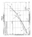
- the value of the torque T delivered by engine 1, expressed in nM, while gear change 5 is in third gear is shown as the abscissa; fuel consumption, expressed as g/s, is shown as the ordinate in that diagram.
- T U and T D Two threshold values of the engine torque T, indicated by T U and T D respectively, are shown in the diagram in Figure 2 .
- Tables or maps M1 and M2 are provided on the basis of the results of test bench tests on engine 1 and (known) values of the transmission ratios ( ⁇ i ) of associated gear change 5.
- processing unit 11 When in operation processing unit 11 therefore compares the instantaneous torque provided by the engine with the threshold values obtained from tables or maps M1 and M2 and - if appropriate - brings about activation of an indicator device 15 to suggest to the driver that it is desirable to change to the immediately higher or lower transmission ratio or gear.
- Indicator device 15 is of any type capable of providing the driver with a perceptible indication, for example of the optical or acoustic type.
- a generator of gear change signals for the electronic unit controlling the gear change may be provided instead of a generator 15 of signals which can be perceived by the driver.
- Maps M1 and M2 may for example be generated using an automatic calibration tool from experimental data obtained on the specific engine.
- the inventors have developed an automatic calibration tool and a checking interface in the MathLab environment.
- the checking interface to which the illustrative diagram in Figure 3 relates, it is possible, after having specified the starting transmission ratio or gear, to move a cursor in the engine rotation speed/delivered engine torque plane in which the isoconsumption curves are drawn, by using a mouse, as may be seen in the diagram in Figure 3 .
- the checking interface developed shows the starting gear ⁇ i (third gear in the example of the graphic in Figure 3 ), the destination gear ⁇ ⁇ +1 (fourth gear in the example in Figure 3 ), and the trajectory between them, in that plane.
- the interface also indicates the corresponding fuel saving being made.
- the interface also shows the threshold lines for suggesting change to the immediately higher transmission ratio and change to the immediately lower transmission ratio.
- first and second table or map are essentially of indicative value, in that maps M1 and M2 described above may simply represent parts of a table or map unit.
- the tables or maps used may also be more than two in number - a further map may be provided to obtain functioning of the "sports" type.
Landscapes
- Engineering & Computer Science (AREA)
- General Engineering & Computer Science (AREA)
- Mechanical Engineering (AREA)
- Control Of Transmission Device (AREA)
Claims (4)
- System (10) zum Vorschlagen eines Gangwechsels in einem Kraftfahrzeug, das mit einem Motor (1) versehen ist, der mit einer Gangschaltung (5) verbunden ist, die eine Vielzahl separater Übersetzungsverhältnisse (τi) herstellen kann, wobei das System (10) umfasst:eine erste und eine zweite Erfassungseinrichtung (12, 13), die in der Lage sind, elektrische Signale bereitzustellen, die das Übersetzungsverhältnis (τi) oder den durch die Gangschaltung (5) eingelegten Gang bzw. die Drehzahl (n) des Motors (1) anzeigen,eine Anzeigeeinrichtung für einen Motor-Parameter (T),eine Speichereinrichtung (14), in der jeweils eine erste sowie eine zweite Tabelle oder ein erstes sowie ein zweites Kennfeld (M1, M2) gespeichert sind, die entsprechende Schwellenwerte (TU; TD) für den Motor-Parameter (T) bereitstellen, unter bzw. über denen angezeigt wird, dass es wünschenswert ist, zu dem unmittelbar höheren Übersetzungsverhältnis (τi+1) bzw. dem unmittelbar niedrigeren Übersetzungsverhältnis (τi-1) in Bezug auf das Übersetzungsverhältnis (τi) zu wechseln, in dem sich die Gangschaltung (5) und die Drehzahl (n) des Motors (1) aktuell befinden, undeine Verarbeitungseinrichtung (11), die funktional mit den Erfassungseinrichtungen (12, 13), der Anzeigeeinrichtung und der Speichereinrichtung (14) verbunden ist und dazu dient, eine Signalerzeugungseinrichtung (15) zu aktivieren, um anzuzeigen, dass es wünschenswert ist, zu dem höheren Übersetzungsverhältnis (τi+1) oder dem niedrigeren Übersetzungsverhältnis (τi-1) zu wechseln, wenn der Motor-Parameter (T) unter dem durch die erste Tabelle oder das erste Kennfeld (M1) bereitgestellten Schwellenwert (TU) liegt, bzw.wenn der Motor-Parameter (T) über dem durch die zweite Tabelle oder das zweite Kennfeld (M2) bereitgestellten Schwellenwert (TD) liegt;wobei das System (10) dadurch gekennzeichnet ist, dass der Motor-Parameter (T) das von dem Motor (1) gelieferte Drehmoment (T) ist.
- System nach Anspruch 1, wobei für jedes Übersetzungsverhältnis (τi) der Gangschaltung (5) und für jeden Wert der Drehzahl (n) des Motors (1) der Schwellenwert (TU) der ersten Tabelle oder des ersten Kennfeldes (M1) unter dem Schwellenwert (TD) der zweiten Tabelle oder des zweiten Kennfeldes (M2) liegt.
- System nach Anspruch 2, wobei die Schwellenwerte (TU; TD) für die erste und die zweite Tabelle oder das erste oder zweite Kennfeld (M1; M2) auf Basis der Ergebnisse von Versuchsstand-Tests des Motors (1) und der Werte der Übersetzungsverhältnisse (τi) der Gangschaltung (5) ermittelt werden.
- System nach Anspruch 3, wobei die Schwellenwerte (TU; TD) auch auf Basis des mechanischen Wirkungsgrades der Gangschaltung (5) in den einzelnen Verhältnissen bestimmt werden.
Applications Claiming Priority (1)
| Application Number | Priority Date | Filing Date | Title |
|---|---|---|---|
| IT000527A ITTO20070527A1 (it) | 2007-07-17 | 2007-07-17 | Sistema per il suggerimento di un cambio di marcia per un autoveicolo provvisto di un motore e di un cambio di velocita a rapporti discreti |
Publications (4)
| Publication Number | Publication Date |
|---|---|
| EP2017505A2 EP2017505A2 (de) | 2009-01-21 |
| EP2017505A3 EP2017505A3 (de) | 2011-08-10 |
| EP2017505B1 true EP2017505B1 (de) | 2012-10-24 |
| EP2017505B8 EP2017505B8 (de) | 2013-02-13 |
Family
ID=39832272
Family Applications (1)
| Application Number | Title | Priority Date | Filing Date |
|---|---|---|---|
| EP08160384A Active EP2017505B8 (de) | 2007-07-17 | 2008-07-15 | System zum Vorschlagen einer Gangänderung für ein Motorfahrzeug mit einem Motor und einer Gangschaltung mit diskreten Verhältnissen |
Country Status (2)
| Country | Link |
|---|---|
| EP (1) | EP2017505B8 (de) |
| IT (1) | ITTO20070527A1 (de) |
Family Cites Families (5)
| Publication number | Priority date | Publication date | Assignee | Title |
|---|---|---|---|---|
| JPS5531669A (en) * | 1978-08-30 | 1980-03-06 | Toyota Motor Corp | Speed change timing instructor for vehicle speed change gear |
| US4441174A (en) | 1981-08-10 | 1984-04-03 | Fairfield Industries, Inc. | Stacked marine seismic source |
| DE3145687C1 (de) * | 1981-11-19 | 1983-06-01 | Daimler-Benz Ag, 7000 Stuttgart | Einrichtung zur UEberwachung des Kraftstoffverbrauchs fuer Kraftfahrzeuge mit Schaltgetriebe |
| JPS5963230A (ja) * | 1982-10-04 | 1984-04-10 | Toyota Motor Corp | 車両の最適シフト時期表示装置 |
| EP0600400B1 (de) * | 1992-12-01 | 1996-10-23 | IFT INGENIEURGESELLSCHAFT FÜR FAHRZEUGTECHNIK mbH | Verfahren und Vorrichtung zur Ermittlung eines günstigen Gangs |
-
2007
- 2007-07-17 IT IT000527A patent/ITTO20070527A1/it unknown
-
2008
- 2008-07-15 EP EP08160384A patent/EP2017505B8/de active Active
Also Published As
| Publication number | Publication date |
|---|---|
| EP2017505A2 (de) | 2009-01-21 |
| EP2017505A3 (de) | 2011-08-10 |
| ITTO20070527A1 (it) | 2009-01-18 |
| EP2017505B8 (de) | 2013-02-13 |
Similar Documents
| Publication | Publication Date | Title |
|---|---|---|
| CN103895637B (zh) | 通过学习驱动方式的车辆的主动控制方法及系统 | |
| JP5005586B2 (ja) | エンジン回転数表示装置 | |
| US4559599A (en) | Optimum shift position indication using successive two-dimensional data maps | |
| JPH02236055A (ja) | 自動変速機の制御装置 | |
| JPH0659790B2 (ja) | 自動トランスミツシヨン装置 | |
| US20080182718A1 (en) | Control device for automatic transmission and control method for automatic transmission | |
| US8755979B2 (en) | Safety control apparatus for automatic transmission and method for controlling automatic transmission | |
| JPH04272568A (ja) | 自動変速機制御装置 | |
| US5245541A (en) | System for and method of controlling automatic transmission | |
| US20180363767A1 (en) | Transmission control device detecting state of shift level and vehicle using the same | |
| US8543284B2 (en) | Vehicle speed sensor diagnostic system and method | |
| KR20000077282A (ko) | 동력 전달 계열 토크 제어 | |
| US9791038B2 (en) | Control method of transmission for vehicle and control system for the same | |
| JP4538306B2 (ja) | 車両用自動変速機の変速制御方法及びシステム | |
| EP2017505B1 (de) | System zum Vorschlagen einer Gangänderung für ein Motorfahrzeug mit einem Motor und einer Gangschaltung mit diskreten Verhältnissen | |
| US6793606B2 (en) | Shift control method for shifting an automatic transmission to a forward driving range while driving in a reverse driving range | |
| SE512460C2 (sv) | Förfarande och anordning för styrning av en automatiserad växellåda | |
| JPH1018896A (ja) | 車速検出装置の故障診断装置 | |
| EP2868904B1 (de) | Steuerungsvorrichtung für einen verbrennungsmotor | |
| KR100354023B1 (ko) | 차량용 자동변속기의 연비 제어방법 | |
| JP3218373B2 (ja) | 自動車用自動変速機の変速制御装置 | |
| CN104675985A (zh) | 用于机动车的选挡装置 | |
| US12246712B2 (en) | Vehicle constant speed travel control method and vehicle constant speed travel control device | |
| JP6086040B2 (ja) | 車両用エンジン回転数表示装置及び車両用エンジン回転数表示装置の制御方法 | |
| JP4696692B2 (ja) | 自動変速制御装置 |
Legal Events
| Date | Code | Title | Description |
|---|---|---|---|
| PUAI | Public reference made under article 153(3) epc to a published international application that has entered the european phase |
Free format text: ORIGINAL CODE: 0009012 |
|
| AK | Designated contracting states |
Kind code of ref document: A2 Designated state(s): AT BE BG CH CY CZ DE DK EE ES FI FR GB GR HR HU IE IS IT LI LT LU LV MC MT NL NO PL PT RO SE SI SK TR |
|
| AX | Request for extension of the european patent |
Extension state: AL BA MK RS |
|
| PUAL | Search report despatched |
Free format text: ORIGINAL CODE: 0009013 |
|
| AK | Designated contracting states |
Kind code of ref document: A3 Designated state(s): AT BE BG CH CY CZ DE DK EE ES FI FR GB GR HR HU IE IS IT LI LT LU LV MC MT NL NO PL PT RO SE SI SK TR |
|
| AX | Request for extension of the european patent |
Extension state: AL BA MK RS |
|
| RIC1 | Information provided on ipc code assigned before grant |
Ipc: F16H 63/42 20060101AFI20110701BHEP |
|
| 17P | Request for examination filed |
Effective date: 20120210 |
|
| GRAP | Despatch of communication of intention to grant a patent |
Free format text: ORIGINAL CODE: EPIDOSNIGR1 |
|
| AKX | Designation fees paid |
Designated state(s): AT BE BG CH CY CZ DE DK EE ES FI FR GB GR HR HU IE IS IT LI LT LU LV MC MT NL NO PL PT RO SE SI SK TR |
|
| GRAS | Grant fee paid |
Free format text: ORIGINAL CODE: EPIDOSNIGR3 |
|
| GRAA | (expected) grant |
Free format text: ORIGINAL CODE: 0009210 |
|
| AK | Designated contracting states |
Kind code of ref document: B1 Designated state(s): AT BE BG CH CY CZ DE DK EE ES FI FR GB GR HR HU IE IS IT LI LT LU LV MC MT NL NO PL PT RO SE SI SK TR |
|
| REG | Reference to a national code |
Ref country code: GB Ref legal event code: FG4D |
|
| REG | Reference to a national code |
Ref country code: CH Ref legal event code: EP |
|
| REG | Reference to a national code |
Ref country code: DE Ref legal event code: R082 Ref document number: 602008019564 Country of ref document: DE Representative=s name: , |
|
| REG | Reference to a national code |
Ref country code: AT Ref legal event code: REF Ref document number: 581137 Country of ref document: AT Kind code of ref document: T Effective date: 20121115 |
|
| REG | Reference to a national code |
Ref country code: IE Ref legal event code: FG4D |
|
| REG | Reference to a national code |
Ref country code: DE Ref legal event code: R096 Ref document number: 602008019564 Country of ref document: DE Effective date: 20121220 |
|
| RIN2 | Information on inventor provided after grant (corrected) |
Inventor name: DE CRISTOFARO, FERDINANDO Inventor name: SEPE, EDUARDO Inventor name: RIEGEL, ALESSANDRO |
|
| RIN2 | Information on inventor provided after grant (corrected) |
Inventor name: DE CRISTOFARO, FERDINANDO Inventor name: SEPE, EDUARDO Inventor name: RIEGEL, ALESSANDRO |
|
| REG | Reference to a national code |
Ref country code: AT Ref legal event code: MK05 Ref document number: 581137 Country of ref document: AT Kind code of ref document: T Effective date: 20121024 |
|
| REG | Reference to a national code |
Ref country code: DE Ref legal event code: R083 Ref document number: 602008019564 Country of ref document: DE |
|
| REG | Reference to a national code |
Ref country code: NL Ref legal event code: VDEP Effective date: 20121024 |
|
| PG25 | Lapsed in a contracting state [announced via postgrant information from national office to epo] |
Ref country code: SE Free format text: LAPSE BECAUSE OF FAILURE TO SUBMIT A TRANSLATION OF THE DESCRIPTION OR TO PAY THE FEE WITHIN THE PRESCRIBED TIME-LIMIT Effective date: 20121024 Ref country code: FI Free format text: LAPSE BECAUSE OF FAILURE TO SUBMIT A TRANSLATION OF THE DESCRIPTION OR TO PAY THE FEE WITHIN THE PRESCRIBED TIME-LIMIT Effective date: 20121024 Ref country code: NO Free format text: LAPSE BECAUSE OF FAILURE TO SUBMIT A TRANSLATION OF THE DESCRIPTION OR TO PAY THE FEE WITHIN THE PRESCRIBED TIME-LIMIT Effective date: 20130124 Ref country code: IS Free format text: LAPSE BECAUSE OF FAILURE TO SUBMIT A TRANSLATION OF THE DESCRIPTION OR TO PAY THE FEE WITHIN THE PRESCRIBED TIME-LIMIT Effective date: 20130224 Ref country code: NL Free format text: LAPSE BECAUSE OF FAILURE TO SUBMIT A TRANSLATION OF THE DESCRIPTION OR TO PAY THE FEE WITHIN THE PRESCRIBED TIME-LIMIT Effective date: 20121024 Ref country code: HR Free format text: LAPSE BECAUSE OF FAILURE TO SUBMIT A TRANSLATION OF THE DESCRIPTION OR TO PAY THE FEE WITHIN THE PRESCRIBED TIME-LIMIT Effective date: 20121024 |
|
| PG25 | Lapsed in a contracting state [announced via postgrant information from national office to epo] |
Ref country code: LV Free format text: LAPSE BECAUSE OF FAILURE TO SUBMIT A TRANSLATION OF THE DESCRIPTION OR TO PAY THE FEE WITHIN THE PRESCRIBED TIME-LIMIT Effective date: 20121024 Ref country code: CY Free format text: LAPSE BECAUSE OF FAILURE TO SUBMIT A TRANSLATION OF THE DESCRIPTION OR TO PAY THE FEE WITHIN THE PRESCRIBED TIME-LIMIT Effective date: 20121024 Ref country code: SI Free format text: LAPSE BECAUSE OF FAILURE TO SUBMIT A TRANSLATION OF THE DESCRIPTION OR TO PAY THE FEE WITHIN THE PRESCRIBED TIME-LIMIT Effective date: 20121024 Ref country code: PL Free format text: LAPSE BECAUSE OF FAILURE TO SUBMIT A TRANSLATION OF THE DESCRIPTION OR TO PAY THE FEE WITHIN THE PRESCRIBED TIME-LIMIT Effective date: 20121024 Ref country code: PT Free format text: LAPSE BECAUSE OF FAILURE TO SUBMIT A TRANSLATION OF THE DESCRIPTION OR TO PAY THE FEE WITHIN THE PRESCRIBED TIME-LIMIT Effective date: 20130225 Ref country code: BE Free format text: LAPSE BECAUSE OF FAILURE TO SUBMIT A TRANSLATION OF THE DESCRIPTION OR TO PAY THE FEE WITHIN THE PRESCRIBED TIME-LIMIT Effective date: 20121024 Ref country code: GR Free format text: LAPSE BECAUSE OF FAILURE TO SUBMIT A TRANSLATION OF THE DESCRIPTION OR TO PAY THE FEE WITHIN THE PRESCRIBED TIME-LIMIT Effective date: 20130125 |
|
| PG25 | Lapsed in a contracting state [announced via postgrant information from national office to epo] |
Ref country code: AT Free format text: LAPSE BECAUSE OF FAILURE TO SUBMIT A TRANSLATION OF THE DESCRIPTION OR TO PAY THE FEE WITHIN THE PRESCRIBED TIME-LIMIT Effective date: 20121024 |
|
| PG25 | Lapsed in a contracting state [announced via postgrant information from national office to epo] |
Ref country code: EE Free format text: LAPSE BECAUSE OF FAILURE TO SUBMIT A TRANSLATION OF THE DESCRIPTION OR TO PAY THE FEE WITHIN THE PRESCRIBED TIME-LIMIT Effective date: 20121024 Ref country code: SK Free format text: LAPSE BECAUSE OF FAILURE TO SUBMIT A TRANSLATION OF THE DESCRIPTION OR TO PAY THE FEE WITHIN THE PRESCRIBED TIME-LIMIT Effective date: 20121024 Ref country code: BG Free format text: LAPSE BECAUSE OF FAILURE TO SUBMIT A TRANSLATION OF THE DESCRIPTION OR TO PAY THE FEE WITHIN THE PRESCRIBED TIME-LIMIT Effective date: 20130124 Ref country code: DK Free format text: LAPSE BECAUSE OF FAILURE TO SUBMIT A TRANSLATION OF THE DESCRIPTION OR TO PAY THE FEE WITHIN THE PRESCRIBED TIME-LIMIT Effective date: 20121024 Ref country code: CZ Free format text: LAPSE BECAUSE OF FAILURE TO SUBMIT A TRANSLATION OF THE DESCRIPTION OR TO PAY THE FEE WITHIN THE PRESCRIBED TIME-LIMIT Effective date: 20121024 |
|
| PG25 | Lapsed in a contracting state [announced via postgrant information from national office to epo] |
Ref country code: RO Free format text: LAPSE BECAUSE OF FAILURE TO SUBMIT A TRANSLATION OF THE DESCRIPTION OR TO PAY THE FEE WITHIN THE PRESCRIBED TIME-LIMIT Effective date: 20121024 |
|
| PLBE | No opposition filed within time limit |
Free format text: ORIGINAL CODE: 0009261 |
|
| STAA | Information on the status of an ep patent application or granted ep patent |
Free format text: STATUS: NO OPPOSITION FILED WITHIN TIME LIMIT |
|
| 26N | No opposition filed |
Effective date: 20130725 |
|
| PG25 | Lapsed in a contracting state [announced via postgrant information from national office to epo] |
Ref country code: ES Free format text: LAPSE BECAUSE OF FAILURE TO SUBMIT A TRANSLATION OF THE DESCRIPTION OR TO PAY THE FEE WITHIN THE PRESCRIBED TIME-LIMIT Effective date: 20130204 |
|
| REG | Reference to a national code |
Ref country code: DE Ref legal event code: R097 Ref document number: 602008019564 Country of ref document: DE Effective date: 20130725 |
|
| PG25 | Lapsed in a contracting state [announced via postgrant information from national office to epo] |
Ref country code: MC Free format text: LAPSE BECAUSE OF FAILURE TO SUBMIT A TRANSLATION OF THE DESCRIPTION OR TO PAY THE FEE WITHIN THE PRESCRIBED TIME-LIMIT Effective date: 20121024 |
|
| REG | Reference to a national code |
Ref country code: CH Ref legal event code: PL |
|
| GBPC | Gb: european patent ceased through non-payment of renewal fee |
Effective date: 20130715 |
|
| REG | Reference to a national code |
Ref country code: IE Ref legal event code: MM4A |
|
| PG25 | Lapsed in a contracting state [announced via postgrant information from national office to epo] |
Ref country code: CH Free format text: LAPSE BECAUSE OF NON-PAYMENT OF DUE FEES Effective date: 20130731 Ref country code: GB Free format text: LAPSE BECAUSE OF NON-PAYMENT OF DUE FEES Effective date: 20130715 Ref country code: LI Free format text: LAPSE BECAUSE OF NON-PAYMENT OF DUE FEES Effective date: 20130731 |
|
| PG25 | Lapsed in a contracting state [announced via postgrant information from national office to epo] |
Ref country code: LT Free format text: LAPSE BECAUSE OF FAILURE TO SUBMIT A TRANSLATION OF THE DESCRIPTION OR TO PAY THE FEE WITHIN THE PRESCRIBED TIME-LIMIT Effective date: 20121024 Ref country code: IE Free format text: LAPSE BECAUSE OF NON-PAYMENT OF DUE FEES Effective date: 20130715 |
|
| PG25 | Lapsed in a contracting state [announced via postgrant information from national office to epo] |
Ref country code: MT Free format text: LAPSE BECAUSE OF FAILURE TO SUBMIT A TRANSLATION OF THE DESCRIPTION OR TO PAY THE FEE WITHIN THE PRESCRIBED TIME-LIMIT Effective date: 20121024 |
|
| PG25 | Lapsed in a contracting state [announced via postgrant information from national office to epo] |
Ref country code: LU Free format text: LAPSE BECAUSE OF NON-PAYMENT OF DUE FEES Effective date: 20130715 Ref country code: HU Free format text: LAPSE BECAUSE OF FAILURE TO SUBMIT A TRANSLATION OF THE DESCRIPTION OR TO PAY THE FEE WITHIN THE PRESCRIBED TIME-LIMIT; INVALID AB INITIO Effective date: 20080715 |
|
| REG | Reference to a national code |
Ref country code: FR Ref legal event code: PLFP Year of fee payment: 9 |
|
| REG | Reference to a national code |
Ref country code: FR Ref legal event code: PLFP Year of fee payment: 10 |
|
| REG | Reference to a national code |
Ref country code: FR Ref legal event code: PLFP Year of fee payment: 11 |
|
| PGFP | Annual fee paid to national office [announced via postgrant information from national office to epo] |
Ref country code: IT Payment date: 20220608 Year of fee payment: 15 |
|
| PGFP | Annual fee paid to national office [announced via postgrant information from national office to epo] |
Ref country code: TR Payment date: 20220703 Year of fee payment: 15 Ref country code: DE Payment date: 20220620 Year of fee payment: 15 |
|
| PGFP | Annual fee paid to national office [announced via postgrant information from national office to epo] |
Ref country code: FR Payment date: 20220726 Year of fee payment: 15 |
|
| REG | Reference to a national code |
Ref country code: DE Ref legal event code: R119 Ref document number: 602008019564 Country of ref document: DE |
|
| PG25 | Lapsed in a contracting state [announced via postgrant information from national office to epo] |
Ref country code: DE Free format text: LAPSE BECAUSE OF NON-PAYMENT OF DUE FEES Effective date: 20240201 |
|
| PG25 | Lapsed in a contracting state [announced via postgrant information from national office to epo] |
Ref country code: FR Free format text: LAPSE BECAUSE OF NON-PAYMENT OF DUE FEES Effective date: 20230731 |
|
| PG25 | Lapsed in a contracting state [announced via postgrant information from national office to epo] |
Ref country code: IT Free format text: LAPSE BECAUSE OF NON-PAYMENT OF DUE FEES Effective date: 20230715 |